EP1586951A1 - Method and device for applying an electrophotographic photoreceptor layer onto a substrate - Google Patents
Method and device for applying an electrophotographic photoreceptor layer onto a substrate Download PDFInfo
- Publication number
- EP1586951A1 EP1586951A1 EP05008089A EP05008089A EP1586951A1 EP 1586951 A1 EP1586951 A1 EP 1586951A1 EP 05008089 A EP05008089 A EP 05008089A EP 05008089 A EP05008089 A EP 05008089A EP 1586951 A1 EP1586951 A1 EP 1586951A1
- Authority
- EP
- European Patent Office
- Prior art keywords
- coating
- substrate
- washing
- supporting member
- substrate supporting
- Prior art date
- Legal status (The legal status is an assumption and is not a legal conclusion. Google has not performed a legal analysis and makes no representation as to the accuracy of the status listed.)
- Granted
Links
Images


Classifications
-
- G—PHYSICS
- G03—PHOTOGRAPHY; CINEMATOGRAPHY; ANALOGOUS TECHNIQUES USING WAVES OTHER THAN OPTICAL WAVES; ELECTROGRAPHY; HOLOGRAPHY
- G03G—ELECTROGRAPHY; ELECTROPHOTOGRAPHY; MAGNETOGRAPHY
- G03G5/00—Recording-members for original recording by exposure, e.g. to light, to heat or to electrons; Manufacture thereof; Selection of materials therefor
- G03G5/02—Charge-receiving layers
- G03G5/04—Photoconductive layers; Charge-generation layers or charge-transporting layers; Additives therefor; Binders therefor
- G03G5/05—Organic bonding materials; Methods for coating a substrate with a photoconductive layer; Inert supplements for use in photoconductive layers
- G03G5/0525—Coating methods
-
- G—PHYSICS
- G03—PHOTOGRAPHY; CINEMATOGRAPHY; ANALOGOUS TECHNIQUES USING WAVES OTHER THAN OPTICAL WAVES; ELECTROGRAPHY; HOLOGRAPHY
- G03G—ELECTROGRAPHY; ELECTROPHOTOGRAPHY; MAGNETOGRAPHY
- G03G5/00—Recording-members for original recording by exposure, e.g. to light, to heat or to electrons; Manufacture thereof; Selection of materials therefor
- G03G5/02—Charge-receiving layers
- G03G5/04—Photoconductive layers; Charge-generation layers or charge-transporting layers; Additives therefor; Binders therefor
- G03G5/05—Organic bonding materials; Methods for coating a substrate with a photoconductive layer; Inert supplements for use in photoconductive layers
-
- G—PHYSICS
- G03—PHOTOGRAPHY; CINEMATOGRAPHY; ANALOGOUS TECHNIQUES USING WAVES OTHER THAN OPTICAL WAVES; ELECTROGRAPHY; HOLOGRAPHY
- G03G—ELECTROGRAPHY; ELECTROPHOTOGRAPHY; MAGNETOGRAPHY
- G03G5/00—Recording-members for original recording by exposure, e.g. to light, to heat or to electrons; Manufacture thereof; Selection of materials therefor
- G03G5/14—Inert intermediate or cover layers for charge-receiving layers
- G03G5/147—Cover layers
- G03G5/14704—Cover layers comprising inorganic material
-
- G—PHYSICS
- G03—PHOTOGRAPHY; CINEMATOGRAPHY; ANALOGOUS TECHNIQUES USING WAVES OTHER THAN OPTICAL WAVES; ELECTROGRAPHY; HOLOGRAPHY
- G03G—ELECTROGRAPHY; ELECTROPHOTOGRAPHY; MAGNETOGRAPHY
- G03G5/00—Recording-members for original recording by exposure, e.g. to light, to heat or to electrons; Manufacture thereof; Selection of materials therefor
- G03G5/14—Inert intermediate or cover layers for charge-receiving layers
- G03G5/147—Cover layers
- G03G5/14708—Cover layers comprising organic material
- G03G5/14713—Macromolecular material
- G03G5/14747—Macromolecular material obtained otherwise than by reactions only involving carbon-to-carbon unsaturated bonds
- G03G5/14756—Polycarbonates
Definitions
- the present invention relates to a method for preparing an electrophotographic photoreceptor. More particularly, the present invention relates to a method for preparing a cylindrical electrophotographic photoreceptor in which a peripheral surface of a cylindrical substrate is coated with a coating liquid by moving a coating head relative to the substrate. In addition, the present invention also relates to a coating device for use in the method.
- Electrophotographic photoreceptors are typically prepared by coating a photosensitive material on a peripheral surface of a cylindrical substrate.
- a dip coating method in which an electroconductive substrate is dipped into a coating liquid vessel containing a photosensitive layer coating liquid and then pulled up is typically used. In this case, the substrate is moved relative to the coating liquid vessel.
- a so-called ring coating method in which a coating head containing a coating liquid is moved along the cylindrical substrate to be coated to reduce the dipping time and uniformize the dipping time for the upper and lower portions of the substrate is used.
- a sealingmember is typically provided between the coating liquid vessel in the coating head and the cylindrical substrate to prevent leakage of the coating liquid from the coating liquid vessel. Therefore, when the coating operation is not performed (i.e., the coating device is in a waiting state), a substrate supporting member, which is configured to hold the cylindrical substrate during coating is performed, is arranged in the coating vessel to prevent leakage of the coating liquid. When coating operation is started, the substrate supporting member is coated with the coating liquid, thereby causing a problem in that a coating liquid residue (i.e., a dried or semi-dried coating liquid) inevitably adheres on the substrate supporting member when coating is continuously performed.
- a coating liquid residue i.e., a dried or semi-dried coating liquid
- JP-A Japanese patent application No.
- JP-A 10-80656 discloses a method in which the coated liquid is uniformly scraped.
- the former method has a drawback in that the thickness of the layer varies when the pump used for feeding the coating liquid causes pulsation.
- the latter method has a drawback in that the gap between the scraper and the surface of the substrate easily varies, resulting in variation of the layer thickness.
- these methods have a drawback in that the coating devices have a complex mechanism and therefore the devices become large in size.
- the uneven layer thickness problem can be solved.
- the coating methods have a drawback in that a coating liquid residue which includes the resin and the filler in the coating liquid is adhered to the substrate supporting member.
- a coating defect is caused.
- Such a coating defect causes a fatal image defect.
- JP-A 2004-279918 proposes to use a washing liquid vessel in which the substrate supporting member is washed.
- the coating defect problem caused by adhesion of coating liquid residues to the photoreceptor cannot be fully solved only by performing such a washing operation.
- the coating liquid includes a filler, a problem in that the filler precipitates in the coating liquid vessel, resulting in formation of residues. These residues cause coating defects, resulting in formation of image defects.
- an object of the present invention is to provide a coating method which solves the above-mentioned problems and by which a layer having good film properties can be formed with hardly causing the coating defects caused by coating liquid residues.
- Another object of the present invention is to provide a coating device which can form a layer having good film properties with hardly causing the coating defects caused by coating liquid residues.
- a method for coating a coating liquid on a cylindrical substrate including:
- the washing liquid is preferably replaced with a fresh washing liquid at a frequency not less than 3 times per a 1 hour coating operation.
- the washing device preferably has a washing element configured to wash the surface of the first substrate supporting member while contacting the surface.
- the washing operation is preferably performed while the surface of the washing liquid in the washing liquid vessel is controlled to be constant.
- the washing liquid preferably includes a solvent of the same kind as that included in the coating liquid.
- the washing operation is preferably performed while irradiating the first substrate supporting member with an ultrasonic wave with a frequency of from 20 to 100 kHz.
- the washing operation is preferably performed while oscillating and/or rotating the first substrate supporting member.
- the washing operation is preferably performed while oscillating and/or rotating the washing device.
- a coating device which includes:
- the washing device preferably includes an overflow wall configured to control the surface of the washing liquid to be constant.
- the transport member holds the upper substrate supporting member with a positional pin, and a holding member.
- each of the upper and lower substrate supporting members has an upper narrow portion and a lower narrow portion thereof, wherein at least one of the upper and lower narrow portions has a recessed portion, and wherein the holding member has a projected portion configured to engage with the recessed portion of the upper substrate supporting member.
- FIG. 1 is a schematic view illustrating the entire of an embodiment of the coating device of the present invention.
- a coating device 100 includes a table 1 and a wall 2 which is located on the table 1 and forms a cylindrical space A.
- a coating liquid is fed by a pump 4 from a coating liquid tank 3 to a coating liquid vessel 51 in a coating head 5, which is located at an upper portion of the space A before a coating operation.
- a ball screw 6 is provided along the wall 2.
- the ball screw 6 is driven by a motor 7.
- an upper substrate supporting member 91 and a lower substrate supporting member 92 are provided to sandwich a cylindrical substrate 8 to be coated.
- the upper substrate supporting member 91 is engaged with a transport member 10, and the lower substrate supporting member 92 is provided on a substrate supporting member table 11.
- a reversing mechanism 12 is provided between the table 1 and the substrate supporting member table 11. The reversing mechanism 12 changes the coated substrate with the following substrate to be coated.
- the coating liquid tank 3 and the coating liquid vessel 51 are connected by a feeding pipe 14 and a collection pipe 15, wherein a valve 13 is provided in the feed pipe 14, to circulate the coating liquid between the coating liquid tank 3 and the coating liquid vessel 51.
- Numeral 16 denotes a washing device configured to wash the substrate supporting members 91 and 92.
- the coating liquid vessel 51 is elevated (i.e., is moved up and down) by the motor 7, and thereby the coating liquid in the coating liquid vessel 51 is coated on the peripheral surface of the cylindrical substrate 8, resulting in formation of a layer constituting an electrophotographic photoreceptor.
- FIG. 2 is an enlarged view illustrating the coating head 5.
- a sealingmember 18 is provided in the coating head 5.
- the sealing member 18 is brought into contact with the cylindrical substrate 8.
- the sealing member 18 is brought into contact with the substrate supporting member 91 or 92.
- a coating liquid 17 is prevented from leaking from the coating head 5. Since the coating liquid vessel 51 is always filled with the coating liquid 17 and in addition the coating liquid 17 is circulated, occurrence of residues due to solidification of the coating liquid can be prevented.
- the inner and outer surfaces of the coating liquid vessel 51 are subjected to an electroconductive treatment.
- the sealing member 18 has a circular opening 18a through which the cylindrical substrate 8 is inserted.
- the sealing member 18 is preferably made of a material (such as fluorine-containing resins or rubbers) having a good resistance to the solvent included in the coating liquid 17.
- the coating liquid 17 is circulated by the pump 4.
- the coating liquid vessel 51 includes an overflow wall 19, and an excess of the coating liquid 17 overflows from an overflow surface 21. Therefore, a fresh coating liquid is contained in the coating liquid vessel 51 while the surface of the coating liquid 17 is maintained so as to be a constant level.
- the coating liquid 17 When the coating liquid 17 is not circulated (i.e., the coating liquid remains in the coating liquid vessel 51), solidified residues are formed in the coating liquid vessel 51.
- a cover 20 is provided on the coating head 5. An excess of the coating liquid overflowing from the overflow surface 21 is returned to the coating liquid tank 3 through the collection pipe 15.
- the coating liquid 17 is preferably circulated at a flow rate of from 0.01 to 1 liter/min and preferably from 0.1 to 0.5 liter/min.
- the washing device 16 has an overflow wall 25 from which a washing liquid 33 overflow, and thereby the surface of the washing liquid is controlled so as to be on a constant level. Therefore, the washing device 16 has a constant washing ability, i. e. , the washing device produces a good washing effect.
- the washing device 16 is connected with a washing liquid tank 30 by a washing liquid feed pipe 31 and a washing liquid collection pipe 32. Therefore, an excess of the washing liquid overflowing from the overflow wall 25 is fed through the washing liquid collection pipe 32 and a fresh washing liquid is fed from the washing liquid tank 30 to the washing device 16 through the washing liquid feed pipe 31. Thus, the washing liquid 33 is circulated.
- the washing liquid is preferably circulated at a flow rate of from 0.01 to 10 liter/min.
- a flow rate of from 0.01 to 10 liter/min.
- the flow rate is too low, good circulation effect cannot be produced.
- the flow rate is to high, a problem in that residues of the coating liquid included in the washing liquid are adhered to the substrate supporting members 91 and 92, resulting in formation of coating defects tends to occur.
- a washing element is provided on the inner surface of the overflow wall 25 to wash the surface of the substrate supportingmembers 91 and 92.
- materials for use as the washing element include brushes and sponges. Among these materials, brushes are preferably used because re-adhesion of residues on the surface of the substrate supporting members is hardly caused.
- brushes having polypropylene fibers with a thickness of 0.2 mm are preferably used as the brush.
- the replacement operation is preferably performed at a frequency not less than 3 times, more preferably not less than 5 times and even more preferably not less than 10 times, per a 1 hour coating operation.
- Suitable materials for use as the washing liquid include solvents of the same kind as the solvents included in the coating liquid 17. This is because the residues adhered to the substrate supporting members 91 and 92 can be dissolved and thereby the washing efficiency can be improved.
- Specific examples of the washing materials include tetrahydrofuran, cyclohexanone and methyl ethyl ketone.
- the frequency of the supersonic waves is preferably from 20 to 100 kHz and more preferably from 40 to 70 kHz. When the frequency is too high, a problem in that the surface of the substrate supporting members is damaged tends to occur.
- the substrate supporting members and the washing device 16 is oscillated.
- the residues adhered to the substrate supporting members can be easily removed therefrom, resulting in enhancement of the washing efficiency.
- the oscillation is preferably performed at a speed not lower than 20 mm/sec.
- the oscillation distance is preferably longer than the length of the substrate supporting members 91 and 92.
- the rotation operation can be performed alone but is preferably performed in combination with the oscillation operation.
- the rotation is preferably performed at a speed not less than 10 rpm, and more preferably not less than 60 rpm.
- the rotation may be performed in the same direction but it is preferable to change the rotation direction after every 180-degree rotation.
- FIG. 3A is a schematic view illustrating a holding member 40.
- the holding member 40 holds a substrate supporting member 9 (i.e. , the substrate supporting member 91 or 92) .
- Upper and lower narrow portions 9a of the substrate supporting member 9 have an external diameter smaller than the internal diameter of the substrate 8 by 0.5 mm or less (from about 0.5 mm to about 0.05 mm).
- the substrate supporting member 9 is fixed by inserting a positioning pin 41, which is provided on the transport member 10, into a hole of the substrate supporting member 9. In this case, there is a case where the substrate supporting member 9 swings.
- the holding member 40 is provided.
- the substrate supporting member 9 and the substrate 8 are fixedly supported, and thereby a coating liquid can be well coated on the surface of the substrate 8, and the substrate supporting member 9 can be well washed by the washing device 16.
- the diameter of the positioning pin 41 is preferably smaller than the diameter of the positioning hole of the substrate supporting member 9 by 0.1 to 0.5 mm.
- the length of the positioning pin 41 is preferably one fifth or longer of the length of the substrate supporting member 9.
- a holding member 40' holding the lower narrow portion 9a of the substrate supporting member 9 is moved by the ball screw 6 together with the coating head 5. Therefore, the coating head 5 and the substrate supporting member 9 are raised at the same speed after the coating operation is completed.
- the holding member 40 has a chucking mechanism having two arms. When the substrate supporting member 9 is inserted into the cylindrical substrate 8, the arms of the chuck are opened, and thereby the substrate supporting member 9 is released from holding by the holding member 40.
- FIG. 3B is another embodiment of the holding member 40.
- the a groove 43 is formed on the narrow portion of the substrate supporting member 9, while a projection 42 is formed on the holding member 40 such that the projection 42 can be engaged with the groove 43. Therefore, the substrate supporting member 9 can be further fixedly supported by the holding member 40. Therefore, when the substrate supporting member 9 is washed, movement of the substrate supporting member 9 can be prevented, and thereby the substrate supporting member 9 can be uniformly washed.
- the width of the groove 43 is preferably smaller than the width of the projection 42 by 0.1 to 0.5 mm.
- the external diameter of a wide portion 9b of the substrate supportingmember 9 is preferably the same as that of the substrate 8 at a tolerance of ⁇ 0.5 mm or less.
- the tolerance falls in this range. (i.e., the difference in level between the outer surface of the substrate 8 and the outer surface of the wide portion 9b of the substrate supporting member 9 is small)
- the coating head 5 can be smoothly moved without causing a problem in that the coating liquid can be prevented from leaking when the coating head 5 passes through the joint between the substrate supporting member 9 and the substrate 8.
- the basic coating operations of the coating device of the present invention are the same as those illustrated in FIGs. 4-21 of JP-A 2004-179918 .
- the coating operations are as follows.
- the cylindrical substrate 8 is supplied to the coating device by a transporter (not shown)
- the coating liquid 17 is circulated between the coating liquid vessel 51 and the coating liquid tank 3.
- an end of substrate 8 is set on the upper narrow portion 9a of the lower substrate supporting member 9 (i. e. , 92) and then the lower narrow portion 9a is inserted into the upper substrate supporting member 9 (i. e. , 91).
- the positioning pin 41 of the transport member 10 is inserted into the upper substrate supporting member 9 (i.e.
- the coating head 5 is also lowered while synchronized with the movement of the holding member 40. Then the coating head 5 is lowered until the surface of the coating liquid 17 in the coating vessel 5 reaches the lower substrate supporting member 9 (i.e., 92). Thus, the coating liquid 17 is coated on the entire peripheral surface of the cylindrical substrate 8.
- the upper substrate supporting member 9 (91) is raised to be released from the substrate 8. Then the substrate bearing a coated layer thereon is discharged with a transporter (not shown) so as to be subjected to the next treatment.
- the upper substrate supporting member 9 held by the transport member 10 is lowered so as to be washed by the washing device 16.
- the holding member 40 is also lowered together with the transport member.
- the washed upper substrate supporting member 9 is then set on the substrate supporting member table 11 to serve as a lower substrate supporting member configured to hold the lower end of the next one of the substrate 8.
- the lower substrate supporting member 9 (92) is raised together with the coating head 5 to hold the upper end of the next one of the substrate 8.
- the coating head 5 is lowered while the cylindrical substrate 8 is stopped.
- another method in which the cylindrical substrate 8 is raised while the coating head 5 is stopped can also be used. Namely, one or both of the coating head 5 and the substrate 8 are moved relatively to the other.
- the coating liquid 17. is always circulated.
- a method in which the circulation is stopped during the device is in a waiting state or the coating operation is performed can also be used.
- the coating device two substrate supporting members are used while the positions of the substrate supporting members are exchanged.
- the sealing member 18 prevents leakage of the coating liquid 17 by contacting the cylindrical substrate 8.
- another sealingmember which has an opening slightly larger than the outer diameter of the cylindrical substrate 8 so as not to contact the substrate 8 can also be used.
- the coating liquid 17 does not leak from the gap between the sealing member 18 and the cylindrical substrate 8 because of having a surface tension.
- the substrate supporting member 9 is preferably grounded for safty.
- the surface thereof is preferably subjected to an electroconductive treatment using a material such as electroconductive fluorine-containing resins having good resistance to the solvents included in the coating liquid 17.
- the substrate supporting member 9 may be made of a metal subjected to an electroconductive treatment.
- the substrate supporting member 9 may be electrically connected with the substrate 8 by contacting an earth plate (not shown) provided thereon with the substrate 8.
- the substrate supporting member having such an earth plate include members which are made of a material such as aluminum, stainless steels and iron and the surface of which is subjected to a TUFRAM treatment (i.e., a hard alumite layer including a fluorine-containing resin therein) or a Ni-P-PTFE plating treatment, or which is coated with an electroconductive fluorine-containing resin having good resistance to the solvents included in the coating liquid.
- a TUFRAM treatment i.e., a hard alumite layer including a fluorine-containing resin therein
- Ni-P-PTFE plating treatment i.e., Ni-P-PTFE plating treatment
- the materials for use in the cylindrical substrate 8 include drums or sheets made of a metal such as aluminum, copper, iron, zinc and nickel; and drums, plates or sheets which are made of a material such as papers, plastics and glasses and on which a metal such as aluminum, copper, gold, silver, platinum, palladium, titanium, nickel-chromium alloys, stainless steels and copper-indium alloys or an electroconductive metal oxide such as indium oxide and tin oxide is deposited, or an electroconductive layer in which a material such as carbon blacks, indium oxide, tin oxide-antimony oxide powders, metal powders and copper iodide which is dispersed in a binder resin is formed, but are not limited thereto.
- the surface of the substrate 8 can be subjected to various treatments, such as oxidation treatments, treatments using a chemical and coloring treatments, to an extent such that the treatment does not cause any problems concerning image qualities.
- an undercoat layer can be formed on the surface of the cylindrical substrate 8 before the photosensitive layer is formed.
- injection of charges from the substrate to the photosensitive layer can be prevented; the adhesiveness of the photosensitive layer to the substrate 8 can be improved; and reflection of light from the surface of the substrate can be prevented.
- the materials for use in the undercoat layer include known resins such as polyethylene, polypropylene, acrylic resins, methacrylic resins, polyamide resins, vinyl chloride resins, vinyl acetate resins, phenolic resins, epoxy resins, polyester resins, alkyd resins, polycarbonate resins, polyurethane resins, polyimide resins, polyvinylidene chloride resins, polyvinyl acetal resins, vinyl chloride - vinyl acetate copolymers, polyvinyl alcohol, water-soluble polyester resins, nitrocellulose, casein, gelatin, etc.
- the thickness of the undercoat layer is preferably from 0.01 to 10 ⁇ m, and more preferably from 0.3 to 7 ⁇ m.
- a photosensitive layer formed on the surface of the substrate 8 optionally the undercoat layer therebetween by coating a coating liquid.
- the photosensitive layer is not particularly limited and may be a single-layered photosensitive layer or a multi-layered photosensitive layer.
- a multi-layered photosensitive layer including a charge generation layer and a charge transport layer will be explained below.
- the charge generation layer typically include a charge generation material and a binder resin, wherein the charge generation material is dispersed in the binder resin.
- the charge generation materials include pigments and dyes such as azo compounds (e.g., nonoazo dyes, disazo dyes and trisazo dyes), perylene compounds (e.g., perylene acid anhydride and perylene acid imide), indigo compounds (e.g., indigo and thioindigo), polycyclid quinone compounds (e.g., anthraquinones, pyrene quinones and flavanthrones), quinacridone compounds, bisbenzimidazole compounds, indanthrone compounds, squarilium compounds, phthalocyanine compounds (metal-containing phothalocyanine and metal-free phthalocyanine), eutectic complexes of a pyrylium salt compound or a thiopyrylium salt compound with a polycarbonate resin, etc.
- a mixer such as ball mills, attritors and sand mills can be used.
- the charge generation material is dispersed so as to have a volume average particle diameter not greater than 5 ⁇ m, more preferably not greater than 2 ⁇ m and even more preferably not greater than 0. 5 ⁇ m.
- the thickness of the charge generation layer is preferably from 0.1 to 5 ⁇ m, and more preferably from 0.2 to 2 ⁇ m.
- the charge transport layer is typically formed on the charge generation layer by coating a charge transport layer coating liquid which is prepared by dispersing or dissolving a charge transport material and a binder resin in a proper solvent.
- charge transport materials include known charge transport materials such as oxadiazole derivatives (e.g., 2,5-bis(p-diethylaminophenyl)-1,3,4-oxadiazole); pyrazoline derivatives (e.g., 1,3,5-triphenylpyrazoline, and 1-pyridyl-3-(p-diethylaminostyryl)-5-(p-diethylamino-phenyl )pyrazoline); aromatic tertiary amino compounds (e.g., triphenylamine, styryl triphenylamine, and dibenzyl aniline); aromatic tertiary diamino compounds (e.g., N,N-diphenyl-N,N-bis(3-methylphenyl)-1,1-bi
- binder resins for use in the charge transport layer include polycarbonate resins, polyester resins, methacrylic resins, acrylic resins, polyvinyl chloride resins, polyvinylidene chloride resins, polystyrene resins, polyvinyl acetate resins, styrene - butadiene copolymers, vinylidene chloride - acrylonitrile - copolymers, vinyl chloride - vinyl acetate copolymers, vinyl chloride - vinyl acetate - maleic anhydride copolymers, silicone resins, silicone - alkyd resins, phenol - formaldehyde resins, styrene - alkyd resins, poly-N-vinylcarbazole, etc., but are not limited thereto. These resins can be used alone or in combination.
- the weight ratio (CTM/BR) of the charge transport material (CTM) to the binder resin (BR) in the charge transport layer is preferably from 10/1 to 1/5.
- the thickness of the charge transport layer is generally from 5 to 50 ⁇ m and preferably from 10 to 30 ⁇ m.
- a single-layered photosensitive layer is formed by coating a coating liquid which is prepared by, for example, dissolving or dispersing a charge generation material, a charge transport material and a binder resin in a proper solvent, on a substrate or an undercoat layer.
- a protective layer is optionally formed on the charge transport layer or the single-layered photosensitive layer to protect the photosensitive layer and the charge transport layer depending on the image forming apparatus (such as copiers and printers) for which the photoreceptor is used.
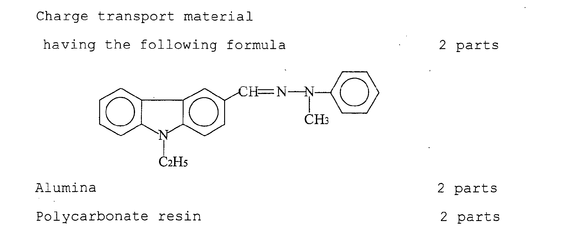
- the protective layer is typically formed by coating a protective layer coating liquid which is typically prepared by dissolving or dispersing a charge transport material, a filler and a binder resin in a proper solvent.
- Specific examples of the filler include inorganic fillers such as alumina and titanium oxide; and organic fillers.
- the content of the filler in the protective layer is preferably from 5 to 30 % by weight.
- the thickness of the protective layer is generally from 2 to 10 ⁇ m, and preferably from 4 to 8 ⁇ m.
- coating liquids such as the undercoat layer coating liquid, charge generation layer coating liquid, charge transport layer coating liquid, single-layered photosensitive layer coating liquid and protective layer coating liquid can be coated by the coating method of the present invention.
- FIG. 4 is a schematic view illustrating a conventional coating device.
- the conventional coating device has a structure similar to that of the coating device illustrated in FIG. 1 except that the washing liquid in the washing device 16 is not circulated.
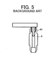
- FIG. 5 is a schematic view illustrating a conventional holding member 44 configured to hold the substrate supporting member.
- the holding member 44 supports the substrate supporting member 9 only by being engaged with the hole in the substrate supporting member 9.
- the undercoat layer coating liquid prepared above was coated on a peripheral surface of a cylindrical aluminum substrate having a diameter of 30 mm and a length of 340 mm by a dip coating method, followed by drying for 15 minutes at 110 °C. Thus, an undercoat layer having a thickness of 5 ⁇ m was prepared.
- the charge generation layer coating liquid prepared above was coated on the undercoat layer by a dip coating method, followed by drying to prepare a charge generation layer with a thickness of 0.2 ⁇ m.
- the charge transport layer coating liquid was coated on the charge generation layer by a dip coating method, followed by drying to prepare a charge transport layer with a thickness of 23 ⁇ m.
- the protective layer coating liquid was coated on the charge transport layer by the above-mentioned coating method (ring coating method) of the present invention, followed by drying to prepare a protective layer with a thickness of 5 ⁇ m.
- the protective layer was prepared using the ring coating device illustrated in FIG. 1.
- the amount of the coating liquid contained in the coating liquid vessel was 0.035 liter, and the coating liquid was circulated at a flow rate of 0.01 liter/min. The coating operation was performed continuously.
- the washing operation was performed while the washing liquid in the washing device was circulated at a flow rate of 1 liter/min, and the washing liquid was replaced 20 times per a 1 hour coating operation.
- each of the thus prepared photoreceptors was visually observed to determine whether the photoreceptor has a coating defect caused by residues of the protective layer coating liquid.
- the photoreceptor was determined to be defective.
- the 30 th photoreceptor was the first defective photoreceptor (i.e., the first to 29 th photoreceptors had no defect).
- Example 1 The procedure for preparation and evaluation of the photoreceptor in Example 1 was repeated except that a brush serving as the washing element illustrated in FIG. 1 and having polypropylene fibers with a thickness of 0.2 mm was provided on the inner surface of the vessel of the washing device to wash the substrate supporting members.
- the 87 th photoreceptor was the first defective photoreceptor.
- the 89 th photoreceptor was the first defective photoreceptor.
- Example 3 The procedure for preparation and evaluation of the photoreceptor in Example 3 was repeated except that during the washing operation, the substrate supporting members were oscillated at a speed of 100 mm/s so as to move back and forth 5 times, wherein the moving distance is 100 mm.
- the 102 nd photoreceptor was the first defective photoreceptor.
- Example 4 The procedure for preparation and evaluation of the photoreceptor in Example 4 was repeated except that during the washing operation,thesubstratesupporting memberswere rotated in such a way that the rotation direction is changed after every 180 degree rotation.
- Example 1 The procedure for preparation and evaluation of the photoreceptor in Example 1 was repeated except that the washing liquid was circulated at a flow rate of 0.01 liter/min.
- the 8 th photoreceptor was the first defective photoreceptor.
- Example 1 The procedure for preparation and evaluation of the photoreceptor in Example 1 was repeated except the coating device was changed to a conventional coating device illustrated in FIG. 4 without changing the amount (0.035 liter) of the coating liquid in the coating liquid vessel and the flow rate (0.01 liter/min) of the coating liquid, and the washing liquid was not circulated.
- the 5 th photoreceptor was the first defective photoreceptor.
- the coating method and coating device of the present invention By using the coating method and coating device of the present invention, occurrence of coating defects caused by residues adhered to the substrate supporting members can be prevented and in addition the degree of swinging of the substrate supporting members during a coating operation can be reduced. Therefore, a coating film having a uniform thickness and good film properties can be formed. Therefore this method can be preferably used for preparing photoreceptors which have good sensitivity and high resolution.
Landscapes
- Physics & Mathematics (AREA)
- General Physics & Mathematics (AREA)
- Chemical & Material Sciences (AREA)
- Chemical Kinetics & Catalysis (AREA)
- Spectroscopy & Molecular Physics (AREA)
- Inorganic Chemistry (AREA)
- Photoreceptors In Electrophotography (AREA)
- Application Of Or Painting With Fluid Materials (AREA)
- Coating Apparatus (AREA)
Abstract
Description
| | 5 |
| Titanium oxide | |
| 20 parts | |
| Cyclohexanone | 35 parts |
| Methyl ethyl ketone | 35 parts |


Claims (12)
- A method for coating a coating liquid (17) on a cylindrical substrate (8), comprising:wherein the coating liquid is circulated between the coating head and a coating liquid tank (3), and wherein the washing liquid is circulated between the washing device and a washing liquid tank (30) at a flow rate of from 0.1 to 10 liter/min.inserting first and second substrate supporting members (9; 91, 92) into upper and lower ends of the cylindrical substrate, respectively, to support the substrate while contacting the coating liquid in a coating liquid vessel (51) of a coating head (5) with the first substrate supporting member;moving the coating head downward relative to the substrate while contacting the coating liquid with the peripheral surface of the substrate to coat the coating liquid thereon;removing the first substrate supporting member from the upper end of the substrate after the surface of the coating liquid reaches the second substrate supporting member;removing the substrate bearing a coating layer thereon from the second substrate supporting member; andupwardly moving the second substrate supporting member together with the coating head to insert the second substrate supporting member into an upper end of next one of the substrate to be coated while transporting the first substrate supporting member to a washing device (16) to wash the first substrate supporting member with a washing liquid (33) contained in the washing device,
- The method according to Claim 1, wherein the washing liquid is replaced with a fresh washing liquid at a frequency not less than 3 times per a 1 hour coating operation.
- The method according to Claim 1 or 2, wherein the washing device comprises a washing element configured to wash the surface of the first substrate supporting member (91) while contacting the surface.
- The method according to any one of Claims 1 to 3, wherein the washing is performed while the surface of the washing liquid (33) in the coating liquid vessel (51) is controlled to be constant.
- The method according to any one of Claims 1 to 4, wherein the washing liquid (33) comprises a solvent of the same kind as that included in the coating liquid.
- The method according to any one of Claims 1 to 5, wherein the washing is performed while irradiating the first substrate supporting member (91) with an ultrasonic wave with a frequency of from 20 to 100 kHz.
- The method according to any one of Claims 1 to 6, wherein the washing is performed while oscillating and/or rotating the first substrate supporting member (91).
- The method according to any one of Claims 1 to 8, wherein the washing is performed while oscillating and/or rotating the washing device (16).
- A coating device (100) comprising:wherein the coating liquid is circulated between the coating head and the coating liquid tank, and wherein the washing liquid is circulated between the washing device and the washing liquid tank at a flow rate of from 0.1 to 10 liter/min.upper and lower substrate supporting members (9; 91, 92) configured to hold upper and lower ends of a cylindrical substrate (8), respectively;a holding member (40) configured to hold the upper substrate supporting member (91);a transport member (10) configured to transport the upper substrate supporting member while holding the upper supporting member;a coating head (5) configured to contain a coating liquid (17) in a coating liquid vessel (51), wherein the coating head is moved relatively to the substrate while contacting the coating liquid with the peripheral surface of the substrate to coat the coating liquid thereon, wherein the coating liquid contacts the upper substrate supporting member before the coating operation and contacts the lower substrate supporting member after the coating operation;a coating liquid tank (3) configured to contain the coating liquid therein;a washing device (16) configured to wash the upper substrate supporting member, which has been transported by the first transport member, with a washing liquid (33) after performing the coating operation and removing the upper substrate supportingmember from the upper end of the cylindrical substrate, wherein the washing operation is performed while moving the lower substrate supporting member together with the coating head to insert the lower substrate supporting member into an upper end of next one of the substrate to be coated; anda washing liquid tank (30) configured to contain the washing liquid,
- The coating device according to Claim 9, wherein the washing device comprises an overflow wall (25) configured to control the surface of the washing liquid to be constant.
- The coating device according to Claim 9 or 10, further comprises a holding member (40), wherein the upper substrate supporting member is held by a positional pin (41) of the transport member (10) and the holding member.
- The coating device according to Claim 11, wherein each of the upper and lower substrate supporting members has an upper narrow portion (9a) and a lower narrow portion (9a) thereof, wherein at least one of the upper and lower narrow portions has a recessed portion (43), and wherein the holding member (40) has a projected portion (42) configured to engage with the recessed portion of the upper substrate supporting member (91) .
Applications Claiming Priority (2)
| Application Number | Priority Date | Filing Date | Title |
|---|---|---|---|
| JP2004119039 | 2004-04-14 | ||
| JP2004119039 | 2004-04-14 |
Publications (2)
| Publication Number | Publication Date |
|---|---|
| EP1586951A1 true EP1586951A1 (en) | 2005-10-19 |
| EP1586951B1 EP1586951B1 (en) | 2008-12-24 |
Family
ID=34935120
Family Applications (1)
| Application Number | Title | Priority Date | Filing Date |
|---|---|---|---|
| EP20050008089 Ceased EP1586951B1 (en) | 2004-04-14 | 2005-04-13 | Method and device for applying an electrophotographic photoreceptor layer onto a substrate |
Country Status (2)
| Country | Link |
|---|---|
| EP (1) | EP1586951B1 (en) |
| DE (1) | DE602005011882D1 (en) |
Citations (3)
| Publication number | Priority date | Publication date | Assignee | Title |
|---|---|---|---|---|
| US6245475B1 (en) * | 1999-12-16 | 2001-06-12 | Xerox Corporation | Process of spray forming photoreceptors with ink nozzles |
| US20020051921A1 (en) * | 2000-09-04 | 2002-05-02 | Tatsuhiro Morita | Coating fluid for electric charge generating layer, organic electrophotographic receptor, and method fo manufacturing the same |
| JP2004279918A (en) * | 2003-03-18 | 2004-10-07 | Ricoh Co Ltd | Electrophotographic photoreceptor coating method and coating apparatus |
-
2005
- 2005-04-13 DE DE200560011882 patent/DE602005011882D1/en not_active Expired - Lifetime
- 2005-04-13 EP EP20050008089 patent/EP1586951B1/en not_active Ceased
Patent Citations (3)
| Publication number | Priority date | Publication date | Assignee | Title |
|---|---|---|---|---|
| US6245475B1 (en) * | 1999-12-16 | 2001-06-12 | Xerox Corporation | Process of spray forming photoreceptors with ink nozzles |
| US20020051921A1 (en) * | 2000-09-04 | 2002-05-02 | Tatsuhiro Morita | Coating fluid for electric charge generating layer, organic electrophotographic receptor, and method fo manufacturing the same |
| JP2004279918A (en) * | 2003-03-18 | 2004-10-07 | Ricoh Co Ltd | Electrophotographic photoreceptor coating method and coating apparatus |
Non-Patent Citations (1)
| Title |
|---|
| PATENT ABSTRACTS OF JAPAN vol. 2003, no. 12 5 December 2003 (2003-12-05) * |
Also Published As
| Publication number | Publication date |
|---|---|
| EP1586951B1 (en) | 2008-12-24 |
| DE602005011882D1 (en) | 2009-02-05 |
Similar Documents
| Publication | Publication Date | Title |
|---|---|---|
| WO2004079455A1 (en) | Basic material for electrophotographic photosensitive body, process for producing the same and electrophotographic photosensitive body employing it | |
| JP3088645B2 (en) | Electrophotographic photoreceptor and method of manufacturing the same | |
| EP1586951B1 (en) | Method and device for applying an electrophotographic photoreceptor layer onto a substrate | |
| JP2004279918A (en) | Electrophotographic photoreceptor coating method and coating apparatus | |
| JPH0534934A (en) | Electrophotographic photoreceptor and method for manufacturing the same | |
| JPH0151184B2 (en) | ||
| JP2004287419A (en) | Electrophotographic photoreceptor substrate, method of manufacturing the substrate, electrophotographic photoreceptor using the substrate, electrophotographic photoreceptor cartridge and image forming apparatus using the electrophotographic photoreceptor | |
| JPH10123737A (en) | Production of electrophotographic photoreceptor, electrophotographic photoreceptor, apparatus for production of electrophotographic photoreceptor and image forming method | |
| JP2005326821A (en) | Electrophotographic photoreceptor coating method and coating apparatus | |
| JP2004246124A (en) | Honing method and method for manufacturing of electrophotographic photoreceptor | |
| JP2005315963A (en) | Spray coating apparatus for electrophotographic photosensitive member and method for producing electrophotographic photosensitive member | |
| JPH1063017A (en) | Coating device for photosensitive layer | |
| JP3215294B2 (en) | Apparatus and method for manufacturing organic electrophotographic photoreceptor | |
| JP3658921B2 (en) | Separation / discharge apparatus and separation / discharge method for coated cylindrical substrate | |
| JPS63244038A (en) | Production of photosensitive body | |
| JP2004177596A (en) | Electrophotographic photoreceptor | |
| JP3237418B2 (en) | Manufacturing method of photoreceptor for electrophotography | |
| JPH05281757A (en) | Method for regenerating electrophotographic sensitive body | |
| JP2000305287A (en) | Apparatus for treating end face of substrate in organic photoreceptor manufacturing apparatus, organic photoreceptor and method for manufacturing the same | |
| US20060147824A1 (en) | Lathe surface for coating streak suppression | |
| JPH11235543A (en) | Method and apparatus for applying paint to cylindrical substrate, and method for manufacturing photosensitive drum for electrophotography | |
| JP2006065053A (en) | Method for manufacturing electrophotographic photoreceptor, stripping liquid for electrophotographic photoreceptor, and electrophotographic photoreceptor | |
| JPH10174922A (en) | Coating apparatus and coating method | |
| JPH02115082A (en) | Coating formation | |
| JP2009222845A (en) | Electrophotographic device |
Legal Events
| Date | Code | Title | Description |
|---|---|---|---|
| PUAI | Public reference made under article 153(3) epc to a published international application that has entered the european phase |
Free format text: ORIGINAL CODE: 0009012 |
|
| AK | Designated contracting states |
Kind code of ref document: A1 Designated state(s): AT BE BG CH CY CZ DE DK EE ES FI FR GB GR HU IE IS IT LI LT LU MC NL PL PT RO SE SI SK TR |
|
| AX | Request for extension of the european patent |
Extension state: AL BA HR LV MK YU |
|
| 17P | Request for examination filed |
Effective date: 20051107 |
|
| AKX | Designation fees paid |
Designated state(s): DE FR GB |
|
| 17Q | First examination report despatched |
Effective date: 20080107 |
|
| GRAP | Despatch of communication of intention to grant a patent |
Free format text: ORIGINAL CODE: EPIDOSNIGR1 |
|
| GRAS | Grant fee paid |
Free format text: ORIGINAL CODE: EPIDOSNIGR3 |
|
| GRAA | (expected) grant |
Free format text: ORIGINAL CODE: 0009210 |
|
| RIN1 | Information on inventor provided before grant (corrected) |
Inventor name: EGAWA, GO Inventor name: UMAYAHARA, TATSUSHI Inventor name: SUZUKI, SAKAE Inventor name: IIYAMA, AKIHIRO Inventor name: YAMAGUCHI, YOSHIHIRO Inventor name: HOSOKAWA, KENJI Inventor name: TAKAGI, KIFUKU |
|
| AK | Designated contracting states |
Kind code of ref document: B1 Designated state(s): DE FR GB |
|
| REG | Reference to a national code |
Ref country code: GB Ref legal event code: FG4D |
|
| REF | Corresponds to: |
Ref document number: 602005011882 Country of ref document: DE Date of ref document: 20090205 Kind code of ref document: P |
|
| PLBE | No opposition filed within time limit |
Free format text: ORIGINAL CODE: 0009261 |
|
| STAA | Information on the status of an ep patent application or granted ep patent |
Free format text: STATUS: NO OPPOSITION FILED WITHIN TIME LIMIT |
|
| 26N | No opposition filed |
Effective date: 20090925 |
|
| REG | Reference to a national code |
Ref country code: DE Ref legal event code: R082 Ref document number: 602005011882 Country of ref document: DE Representative=s name: MEISSNER BOLTE PATENTANWAELTE RECHTSANWAELTE P, DE Ref country code: DE Ref legal event code: R082 Ref document number: 602005011882 Country of ref document: DE Representative=s name: MEISSNER, BOLTE & PARTNER GBR, DE |
|
| REG | Reference to a national code |
Ref country code: DE Ref legal event code: R082 Ref document number: 602005011882 Country of ref document: DE Representative=s name: MEISSNER, BOLTE & PARTNER GBR, DE |
|
| REG | Reference to a national code |
Ref country code: FR Ref legal event code: PLFP Year of fee payment: 12 |
|
| REG | Reference to a national code |
Ref country code: FR Ref legal event code: PLFP Year of fee payment: 13 |
|
| REG | Reference to a national code |
Ref country code: FR Ref legal event code: PLFP Year of fee payment: 14 |
|
| PGFP | Annual fee paid to national office [announced via postgrant information from national office to epo] |
Ref country code: GB Payment date: 20180321 Year of fee payment: 14 |
|
| PGFP | Annual fee paid to national office [announced via postgrant information from national office to epo] |
Ref country code: DE Payment date: 20180420 Year of fee payment: 14 |
|
| PGFP | Annual fee paid to national office [announced via postgrant information from national office to epo] |
Ref country code: FR Payment date: 20180420 Year of fee payment: 14 |
|
| REG | Reference to a national code |
Ref country code: DE Ref legal event code: R119 Ref document number: 602005011882 Country of ref document: DE |
|
| GBPC | Gb: european patent ceased through non-payment of renewal fee |
Effective date: 20190413 |
|
| PG25 | Lapsed in a contracting state [announced via postgrant information from national office to epo] |
Ref country code: DE Free format text: LAPSE BECAUSE OF NON-PAYMENT OF DUE FEES Effective date: 20191101 Ref country code: GB Free format text: LAPSE BECAUSE OF NON-PAYMENT OF DUE FEES Effective date: 20190413 |
|
| PG25 | Lapsed in a contracting state [announced via postgrant information from national office to epo] |
Ref country code: FR Free format text: LAPSE BECAUSE OF NON-PAYMENT OF DUE FEES Effective date: 20190430 |