EP1586937A1 - Reflector for liquid crystal display - Google Patents
Reflector for liquid crystal display Download PDFInfo
- Publication number
- EP1586937A1 EP1586937A1 EP05006731A EP05006731A EP1586937A1 EP 1586937 A1 EP1586937 A1 EP 1586937A1 EP 05006731 A EP05006731 A EP 05006731A EP 05006731 A EP05006731 A EP 05006731A EP 1586937 A1 EP1586937 A1 EP 1586937A1
- Authority
- EP
- European Patent Office
- Prior art keywords
- section
- reflector
- liquid crystal
- shape
- concave portions
- Prior art date
- Legal status (The legal status is an assumption and is not a legal conclusion. Google has not performed a legal analysis and makes no representation as to the accuracy of the status listed.)
- Withdrawn
Links
- 239000004973 liquid crystal related substance Substances 0.000 title claims abstract description 44
- 239000000758 substrate Substances 0.000 claims abstract description 21
- 239000010408 film Substances 0.000 description 31
- 230000000052 comparative effect Effects 0.000 description 6
- 238000005286 illumination Methods 0.000 description 6
- 238000009826 distribution Methods 0.000 description 5
- 229910052751 metal Inorganic materials 0.000 description 5
- 239000002184 metal Substances 0.000 description 5
- 239000003086 colorant Substances 0.000 description 4
- 239000010409 thin film Substances 0.000 description 4
- 230000010287 polarization Effects 0.000 description 3
- 238000012795 verification Methods 0.000 description 3
- 230000003247 decreasing effect Effects 0.000 description 2
- 238000004519 manufacturing process Methods 0.000 description 2
- 238000000034 method Methods 0.000 description 2
- 229910052782 aluminium Inorganic materials 0.000 description 1
- XAGFODPZIPBFFR-UHFFFAOYSA-N aluminium Chemical compound [Al] XAGFODPZIPBFFR-UHFFFAOYSA-N 0.000 description 1
- 230000007423 decrease Effects 0.000 description 1
- 230000002542 deteriorative effect Effects 0.000 description 1
- 239000006185 dispersion Substances 0.000 description 1
- 238000005530 etching Methods 0.000 description 1
- 239000011521 glass Substances 0.000 description 1
- 239000011159 matrix material Substances 0.000 description 1
- 230000003287 optical effect Effects 0.000 description 1
- 238000000206 photolithography Methods 0.000 description 1
- 238000003825 pressing Methods 0.000 description 1
- 239000003566 sealing material Substances 0.000 description 1
Images


Classifications
-
- G—PHYSICS
- G02—OPTICS
- G02F—OPTICAL DEVICES OR ARRANGEMENTS FOR THE CONTROL OF LIGHT BY MODIFICATION OF THE OPTICAL PROPERTIES OF THE MEDIA OF THE ELEMENTS INVOLVED THEREIN; NON-LINEAR OPTICS; FREQUENCY-CHANGING OF LIGHT; OPTICAL LOGIC ELEMENTS; OPTICAL ANALOGUE/DIGITAL CONVERTERS
- G02F1/00—Devices or arrangements for the control of the intensity, colour, phase, polarisation or direction of light arriving from an independent light source, e.g. switching, gating or modulating; Non-linear optics
- G02F1/01—Devices or arrangements for the control of the intensity, colour, phase, polarisation or direction of light arriving from an independent light source, e.g. switching, gating or modulating; Non-linear optics for the control of the intensity, phase, polarisation or colour
- G02F1/13—Devices or arrangements for the control of the intensity, colour, phase, polarisation or direction of light arriving from an independent light source, e.g. switching, gating or modulating; Non-linear optics for the control of the intensity, phase, polarisation or colour based on liquid crystals, e.g. single liquid crystal display cells
- G02F1/133—Constructional arrangements; Operation of liquid crystal cells; Circuit arrangements
- G02F1/1333—Constructional arrangements; Manufacturing methods
- G02F1/1335—Structural association of cells with optical devices, e.g. polarisers or reflectors
- G02F1/133553—Reflecting elements
-
- E—FIXED CONSTRUCTIONS
- E01—CONSTRUCTION OF ROADS, RAILWAYS, OR BRIDGES
- E01D—CONSTRUCTION OF BRIDGES, ELEVATED ROADWAYS OR VIADUCTS; ASSEMBLY OF BRIDGES
- E01D19/00—Structural or constructional details of bridges
- E01D19/06—Arrangement, construction or bridging of expansion joints
- E01D19/065—Joints having sliding plates
-
- G—PHYSICS
- G02—OPTICS
- G02B—OPTICAL ELEMENTS, SYSTEMS OR APPARATUS
- G02B5/00—Optical elements other than lenses
- G02B5/08—Mirrors
- G02B5/10—Mirrors with curved faces
-
- G—PHYSICS
- G02—OPTICS
- G02F—OPTICAL DEVICES OR ARRANGEMENTS FOR THE CONTROL OF LIGHT BY MODIFICATION OF THE OPTICAL PROPERTIES OF THE MEDIA OF THE ELEMENTS INVOLVED THEREIN; NON-LINEAR OPTICS; FREQUENCY-CHANGING OF LIGHT; OPTICAL LOGIC ELEMENTS; OPTICAL ANALOGUE/DIGITAL CONVERTERS
- G02F1/00—Devices or arrangements for the control of the intensity, colour, phase, polarisation or direction of light arriving from an independent light source, e.g. switching, gating or modulating; Non-linear optics
- G02F1/01—Devices or arrangements for the control of the intensity, colour, phase, polarisation or direction of light arriving from an independent light source, e.g. switching, gating or modulating; Non-linear optics for the control of the intensity, phase, polarisation or colour
- G02F1/13—Devices or arrangements for the control of the intensity, colour, phase, polarisation or direction of light arriving from an independent light source, e.g. switching, gating or modulating; Non-linear optics for the control of the intensity, phase, polarisation or colour based on liquid crystals, e.g. single liquid crystal display cells
- G02F1/133—Constructional arrangements; Operation of liquid crystal cells; Circuit arrangements
- G02F1/1333—Constructional arrangements; Manufacturing methods
- G02F1/1335—Structural association of cells with optical devices, e.g. polarisers or reflectors
- G02F1/133553—Reflecting elements
- G02F1/133555—Transflectors
Definitions
- the present invention relates to a reflector having asymmetrical concave portions and a liquid crystal display device having the same. More particularly, it relates to a reflector in which a reflection characteristic is prevented from deteriorating even at a large transmissive opening and a liquid crystal display device having the same.
- a reflection-type liquid crystal display device capable of decreasing the power consumption is provided as a display part, since the lifetime of battery largely affects the convenience of electronic devices.
- the reflection-type liquid crystal display devices are provided with a reflector for total-reflecting external light incident from a front surface or a reflector for reflecting the external light incident from the front surface and transmitting light emitted from a backlight.
- a reflector there is known a reflector provided with a plurality of fine concave or convex portions to maximally increase the reflectance of the reflector (for example, see Japanese Unexamined Patent Application Publication No. 11-52110).
- the reflector for reflecting the external light and transmitting the light emitted from the backlight is referred to as a transflective reflector.
- a transflective reflector openings for transmitting light emitted from an illumination device, such as a backlight, toward the liquid crystal display panel are formed in a portion of a metal thin film having a plurality of fine concave portions thereon, which are formed by either sandblast or photolithography or both. Therefore, the liquid crystal display panel can be brightly illuminated by any light source such as the external light or the illuminating device.
- the shape of each of the concave or convex portions, particularly, the section shape is not controlled by the distribution state of angle of inclination, but the reflection characteristic forms a so-called Gaussian distribution, which is symmetrical with respect to the specular reflection angle in a narrow range. Accordingly, if the openings are formed in the transflective reflector, the reflectance of the wide viewing angle area is significantly deteriorated. Accordingly, there are problems in that the brightness decreases and the image angle becomes narrow, which result in lowering the viewing convenience.
- the present invention has been made in consideration of the above-mentioned problems, and it is an object of the present invention to provide a reflector and a liquid crystal display device having the same, in which the reflectance of the reflector can be highly maintained even though openings are formed in a transflective reflector.
- a reflector having a plurality of concave portions formed on one surface of a base substrate, wherein, when a section passing through a deepest point of each of the concave portions is defined as a first section and a section orthogonal to the first section at the deepest point is defined as a second section, the concave portion has an asymmetrical shape with respect to the first section and has a symmetrical shape with respect to the second section, and an opening surface of the concave portion has an approximately elliptical shape with a long axis in a direction along the first section.
- the opening surface of the concave portion may be formed such that a portion of the approximately elliptical shape includes an approximately straight line extending in the direction along the first section. Further, the concave portion may be formed such that a maximum angle of an inclination of the second section is larger than that of the first section.
- the maximum angle of the inclination of the first section is set in a range of from 5° to 25° and the maximum angle of the inclination of the second section is set in a range of from 15° to 28°. Also, there is provided a liquid crystal display device having the reflector formed in such a manner, a pair of substrates, and a liquid crystal layer interposed therebetween.
- the reflector of the present invention by making the opening surface of the concave portion in the approximately elliptical shape with a long axis in the direction along the first section, the reflectance can be highly maintained, even though the reflector is formed with the transflective reflector and is provided with the openings for transmitting illumination light. Accordingly, when it is used as a reflector in a liquid crystal display device, a bright image display can be performed at a wide viewing angle.
- Fig. 1 is an enlarged cross sectional view schematically showing a liquid crystal display device having a reflector according to the present invention.
- the liquid crystal display device 1 has a liquid crystal display panel 9 integrated by attaching a first substrate 10 and a second substrate 20 which are opposite to each other with a liquid crystal layer 30 therebetween and are composed of a transparent glass by sealing material 40 provided in a ring shape at the periphery of the substrates 10 and 20, and a backlight 5 which is an illuminating device.
- an electrode layer 25, an overcoat film 24 and an orientation film 26 are sequentially laminated.
- the color filters 13 are formed such that three colors of red, green and blue which are primary colors of light are repeated.
- light shielding walls 35 generally referred to as a black matrix are formed between the color filters 13 to prevent the colors from being mixed between the color filters 13.
- Respective regions divided by the light shielding walls 35 constitute respective pixel regions 36.
- a polarization plate 18 is provided at a side opposite to the liquid crystal layer 30 of the first substrate 10 (an external side of the first substrate 10), a phase difference plate 27 and a polarization plate 28 are sequentially laminated at a side opposite to the liquid crystal layer 30 of the second substrate 20 (an external side of the second substrate 20). Also, at an external side of the polarization plate 18 of the first substrate 10, the backlight 5 is provided as an illuminating device for performing transmissive display of the liquid crystal display device 1.
- the organic film (base substrate) 11 is provided to efficiently scatter reflected light by forming concave portions 31 in the transflective reflective film 12 formed thereon. Since external light incident on the liquid crystal display device 1 can be efficiently reflected by forming the concave portions 31 in the transflective reflective film 12, bright display can be accomplished upon illumination due to the external light reflection.
- a method for implementing the reflective film a method of using a block made of a metal as a master blank, manufacturing an individual concave portion in the surface thereof while controlling the shape (depth, pitch and sectional shape) by a fine manufacturing tool corresponding to the above-mentioned sectional shape, and pressing the manufactured mold patterned from the obtained surface to form the shape is preferably employed.
- the transflective reflective film 12 is, for example, formed of a metal thin film having a high reflectance such as aluminum.
- the transflective reflective film 12 is formed with openings 32 in correspondence with each pixel of the liquid crystal display panel 9.
- the opening 32 is to allow light irradiated from the backlight (illuminating device) 5 to transmit the transflective reflective film 12 made of the metal thin film.
- the liquid crystal display device 1 can brightly illuminate the liquid crystal display panel 9 by operation of the transflective reflective film 12 even though any one of the external light and the backlight 5 is used as a light source.
- Fig. 2 is a perspective view showing a portion including the organic film 11 and the transflective reflective film 12 formed thereon.
- a surface of the organic film 11 is successively formed with a plurality of concave portions 11a, an inner surface of each forming a portion of elliptical surface, and the transflective reflective film 12 is laminated thereon.
- the concave portions 11a formed in the surface of the organic film 11 the concave portions 31 are formed in the transflective reflective film 12.
- flat surface of the reflective film can be preferably decreased and bright reflection light can be preferably obtained at wide viewing angle.
- a portion of the transflective reflective film 12 is formed with rectangular openings 32.
- the opening 32 may be formed by, for example, etching.
- Fig. 3 is an enlarged plan view of the portion of the reflector according to the present invention.
- the transflective reflective film 12 is randomly formed with a plurality of the concave portions 31 each of which opening shape is approximately an elliptical shape. Further, the opening 32 surrounding the concave portion 31 is formed.
- the openings 32 are, for example, formed in correspondence with each pixel of the liquid crystal display panel 9 (see Fig. 1).
- Fig. 4 is an enlarged three-side view of one concave portion.
- the concave portion 31 is formed such that the shape of the opening surface S is approximately elliptical.
- an approximate straight line portion L parallel to a first section line X passing through the deepest point P (see a and b in Fig. 4) of the concave portion 31 along a long axis direction of an approximate ellipse may be formed in a portion of the approximate ellipse.
- an opening area of the concave portion can be reduced and the number of the concave portions formed in a region within a predetermined range can be increased in the reflective plate, and thus the bright reflection light can be preferably obtained at a wider viewing angle.
- the concave portion 31 has an asymmetrical shape with respect to the first section (see b in Fig. 4) which becomes wide from the first section line X passing through the deepest point P toward a depth direction and has a symmetrical shape with respect to the second section (see c in Fig. 4) which becomes wide from the second section line Y perpendicular to the first section line X toward the depth direction.
- the concave portion 31 is set such that the maximum angle of inclination R2 of the second section shown by c in Fig. 4 is larger than the maximum angle of inclination R1 of the first section shown by b in Fig. 4.
- the maximum angle of inclination R1 of the first section is in a range of 5° to 25° and, for example, it is set to 13.5°.
- the maximum angle of inclination R2 of the second section is in a range of 15° to 28( and, for example, it is set to 19.1(.
- a radius of curvature of the first section of the concave portion 31 is set to, for example, 40 (m and a radius of curvature of the second section thereof is set to, for example, 20 (m.
- the maximum angle of inclination R1 of the first section is larger than 25(, the shape of the concave portion becomes close to a sphere from the ellipse, and thus it is difficult to significantly improve a reflection strength in a viewer direction. Also, if it is smaller than 5(, the sufficient brightness is obtained with respect to light incident from a front side, but there is a problem in that a rainbow caused by dispersion of the light is generated because the ellipticity is large.
- the maximum angle of inclination R2 of the second section is larger than 28(, it gives a dark impression to the viewer, and, if it is smaller than 15(, the reflection strength in a vicinity of the front side (light receiving angle 0() is reduced, and thus also give a dark impression.
- the depth D of the concave portion 31 from the opening surface S of the concave portion 31 to the deepest point P is set to, for example, 1.1 ⁇ m.
- the width A in the first section line X direction of the concave portion 31 is set to, for example, 18.6 ⁇ m.
- the width B1 from the straight line L to the first section line X in the second section line Y direction of the concave portion 31 is set to, for example, 2.0 ⁇ m
- the width B2 from the first section line X to the top Q of the approximately elliptical shape of the opening surface S is set to, for example, 6.5 ⁇ m.
- a ratio of a radius ⁇ of the long axis along the first section line X direction to a radius P of the short axis along the second section line Y direction is preferably in a range of 1.1 to 1.8, and is more preferably in a range 1.2 to 1.7.
- the concave portion has a shape close to a sphere. Accordingly, when seeing the reflective plate in a plan view, it is difficult to obtain a desired reflection characteristic in a wide range with respect to a vertical direction. Further, if the aspect ratio is larger than 1.8, the desired reflection characteristic in the vertical direction is obtained, but it is difficult to obtain the desired reflection characteristic in a wide range with respect to a horizontal direction.
- the plurality of the concave portions formed in the reflective plate are formed such that the approximate straight line portion L parallel to the first section line X is arranged in a direction far from a viewing point of the viewer.
- the amount of reflected light in a range of 20° from a direction of a normal line for display surface of the liquid crystal display device is increased, the amount of reflected light is increased as it gets closer to the viewing point of the viewer, and a region where the amount of reflected light is high is wider. Accordingly, the liquid crystal display device, which can perform bright display in a practical point of view, particularly, within a range in which an angle formed by the normal line direction and a primary viewing direction is 0° to 20°, can be implemented.
- the concave portion 31 By forming the concave portion 31 in the above-mentioned shape, it is possible to highly maintain the reflectance, although the reflector is formed of the transflective reflective film 12 and the openings 32 for transmitting the illumination light are provided. Therefore, in case of using the reflector in the liquid crystal display device, a bright image can be displayed at a wide viewing angle.
- the present applicant verified the reflection characteristic of the reflector according to the above-mentioned prevent invention.
- two reflectors formed with a plurality of concave portions each of which opening shape is approximately elliptical as shown in Fig. 4 are prepared, and one of the reflectors is formed with transmissive openings with an area ratio of 30% and the other thereof is not formed with the transmissive openings (total reflection).
- two reflectors formed with a plurality of conventional concave portions each of which opening shape is approximately circular are prepared as a comparative example, and one of the reflectors is formed with the transmissive openings with an area ratio of 30% and the other thereof is not formed with the transmissive openings (total reflection).
- Fig. 5 shows the verified results of the reflection characteristics of the reflectors of the present invention and the comparative example.
- the reflection characteristic of the reflector shows a relationship between the brightness (reflectance) and the light receiving angle (°), when external light is irradiated toward the reflection surface by the incidence angle 30° (angle formed by an optical axis of external light illuminated from an opposite side of a viewing point of a viewer who views it from one side of a perpendicular line (normal line) of a reflection surface) and turning the viewing direction (the light receiving angle) from a perpendicular location (the normal location) (0°) to 70°.
- the reflector according to the present invention of which opening shape is approximately elliptical it has been verified that high reflection strength can be obtained in a wide range where the light receiving angle is 0° to 50° regardless of whether or not the reflector has the transmissive openings.
- the reflector according to the present invention of which opening shape is approximately circular so-called Gaussian distribution type reflection strength is obtained regardless of whether or not the reflector has the transmissive openings, so that the high reflection strength can be obtained only in a narrow range where the light receiving angle is 20° to 40°. Further, within this range, there was a rapid change of the reflection strength due to variation of the light receiving angle. From the verified result, if the reflector according to the present invention is used as the reflector of the liquid crystal display device, it has been confirmed that a bright image can be displayed at a wide viewing angle.
- the present applicant verified the reflection characteristic of the reflector according to the present invention.
- two reflectors formed with a plurality of concave portions each of which opening shape is approximately elliptical, as shown in the three-side view of Fig. 6, are prepared, and one of the reflectors is formed with transmissive openings with an area ratio of 30% and the other thereof is not formed with the transmissive openings (total reflection).
- the radius of curvature, the depth and the maximum angle of inclination of each portion of the concave portion are indicated in the Figure.
- Fig. 7 shows the verified results of the reflection characteristics of the reflectors of the present invention and the comparative example.
- the reflector according to the present invention of which opening shape is approximately elliptical it has been verified that high reflection strength can be obtained in a wide range where the light receiving angle is -10° to 30° regardless of whether or not the reflector has the transmissive openings.
- the reflector according to the present invention of which opening shape is approximately circular so-called Gaussian distribution type reflection strength is obtained regardless of whether or not the reflector has the transmissive openings, so that the high reflection strength can be obtained only in a narrow range where the light receiving angle is approximately 30°. Further, even in the narrow range of approximately 30°, there was a rapid change in the reflection strength due to variation of the light receiving angle. From the verified result, if the reflector according to the present invention is used as the reflector of the liquid crystal display device, it has been confirmed that a bright image can be displayed at a wide viewing angle.
- the present applicant verified the reflection characteristic of the reflector according to the present invention.
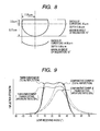
- two reflectors formed with a plurality of concave portions each of which opening shape is approximately elliptical, as shown in the three-side view of Fig. 8, are prepared, and one of the reflectors is formed with transmissive openings with an area ratio of 30% and the other thereof is not formed with the transmissive openings (total reflection).
- the radius of curvature, the depth and the maximum angle of inclination of each portion of the concave portion are indicated in the Figure.
- Fig. 9 shows the verified results of the reflection characteristics of the reflectors of the present invention and the comparative example.
- the reflector according to the present invention of which opening shape is approximately elliptical it has been verified that high reflection strength can be obtained in a wide range where the light receiving angle is 10° to 40° regardless of whether or not the reflector has the transmissive openings.
- the reflector according to the present invention of which opening shape is approximately circular so-called Gaussian distribution type reflection strength is obtained regardless of whether or not the reflector has the transmissive openings, so that the high reflection strength can be obtained only in a narrow range where the light receiving angle is approximately 30°. Further, even in the narrow range of approximately 30°, there was a rapid change in the reflection strength due to variation of the light receiving angle. From the verified result, if the reflector according to the present invention is used as the reflector of the liquid crystal display device, it has been confirmed that a bright image can be displayed at a wide viewing angle.
Landscapes
- Physics & Mathematics (AREA)
- Nonlinear Science (AREA)
- Optics & Photonics (AREA)
- General Physics & Mathematics (AREA)
- Crystallography & Structural Chemistry (AREA)
- Chemical & Material Sciences (AREA)
- Mathematical Physics (AREA)
- Engineering & Computer Science (AREA)
- Architecture (AREA)
- Civil Engineering (AREA)
- Structural Engineering (AREA)
- Liquid Crystal (AREA)
- Optical Elements Other Than Lenses (AREA)
Abstract
A reflector (12) for a liquid crystal display (1). The reflector film
(12), which has openings (32) corresponding to each pixel for use with a
backlight (5), is formed on a substrate (11) to reflect external light.
A plurality of concave portions (31), which have different radii of
curvature (R1,R2) in two orthogonal cross sections (X,Y), are formed on
the surface of the substrate. The shape of the openings of the concave
portions, at the substrate surface, is approximately elliptical, except
in a portion parallel with the long axis of the ellipse where it is
approximately a straight line (L). This results in concave portions
which have an asymmetrical shape, in the direction (Y) of the short axis
of the ellipse, and reflection characteristics which are not symmetrical
in a narrow range in the vertical direction, but allow for a wide
viewing angle in a vertical direction. The concave portions have a
symmetrical shape, in the direction (X) of the long axis of the ellipse,
and symmetrical reflection characteristics in a narrow range in the
horizontal direction to improve the reflection strength in the viewer
direction. An opening surface (S) with an approximately straight line
reduces the opening area, which may be desirable because the number of
concave regions on the surface of a substrate can be increased.
Description
- The present invention relates to a reflector having asymmetrical concave portions and a liquid crystal display device having the same. More particularly, it relates to a reflector in which a reflection characteristic is prevented from deteriorating even at a large transmissive opening and a liquid crystal display device having the same.
- In portable electronic devices such as portable phones or portable game devices, a reflection-type liquid crystal display device capable of decreasing the power consumption is provided as a display part, since the lifetime of battery largely affects the convenience of electronic devices. The reflection-type liquid crystal display devices are provided with a reflector for total-reflecting external light incident from a front surface or a reflector for reflecting the external light incident from the front surface and transmitting light emitted from a backlight. As such a reflector, there is known a reflector provided with a plurality of fine concave or convex portions to maximally increase the reflectance of the reflector (for example, see Japanese Unexamined Patent Application Publication No. 11-52110).
- Among these reflectors, particularly, the reflector for reflecting the external light and transmitting the light emitted from the backlight is referred to as a transflective reflector. In the transflective reflector, openings for transmitting light emitted from an illumination device, such as a backlight, toward the liquid crystal display panel are formed in a portion of a metal thin film having a plurality of fine concave portions thereon, which are formed by either sandblast or photolithography or both. Therefore, the liquid crystal display panel can be brightly illuminated by any light source such as the external light or the illuminating device.
- However, in the above-mentioned conventional reflector, the shape of each of the concave or convex portions, particularly, the section shape is not controlled by the distribution state of angle of inclination, but the reflection characteristic forms a so-called Gaussian distribution, which is symmetrical with respect to the specular reflection angle in a narrow range. Accordingly, if the openings are formed in the transflective reflector, the reflectance of the wide viewing angle area is significantly deteriorated. Accordingly, there are problems in that the brightness decreases and the image angle becomes narrow, which result in lowering the viewing convenience.
- The present invention has been made in consideration of the above-mentioned problems, and it is an object of the present invention to provide a reflector and a liquid crystal display device having the same, in which the reflectance of the reflector can be highly maintained even though openings are formed in a transflective reflector.
- In order to achieve the above object, according to the present invention, there is provided a reflector having a plurality of concave portions formed on one surface of a base substrate, wherein, when a section passing through a deepest point of each of the concave portions is defined as a first section and a section orthogonal to the first section at the deepest point is defined as a second section, the concave portion has an asymmetrical shape with respect to the first section and has a symmetrical shape with respect to the second section, and an opening surface of the concave portion has an approximately elliptical shape with a long axis in a direction along the first section.
- The opening surface of the concave portion may be formed such that a portion of the approximately elliptical shape includes an approximately straight line extending in the direction along the first section. Further, the concave portion may be formed such that a maximum angle of an inclination of the second section is larger than that of the first section.
- It is preferable that the maximum angle of the inclination of the first section is set in a range of from 5° to 25° and the maximum angle of the inclination of the second section is set in a range of from 15° to 28°. Also, there is provided a liquid crystal display device having the reflector formed in such a manner, a pair of substrates, and a liquid crystal layer interposed therebetween.
- According to the reflector of the present invention, by making the opening surface of the concave portion in the approximately elliptical shape with a long axis in the direction along the first section, the reflectance can be highly maintained, even though the reflector is formed with the transflective reflector and is provided with the openings for transmitting illumination light. Accordingly, when it is used as a reflector in a liquid crystal display device, a bright image display can be performed at a wide viewing angle.
-
- Fig. 1 is a cross sectional view showing a liquid crystal display device having a reflector according to the present invention;
- Fig. 2 is an enlarged perspective view of the reflector shown in Fig. 1;
- Fig. 3 is an enlarged plan view of a vicinity of an opening of the reflector shown in Fig. 1;
- Fig. 4 is an enlarged three-side view of a concave portion constituting the reflector;
- Fig. 5 is a graph showing a verified result of the reflector according to the prevent invention;
- Fig. 6 is another enlarged three-side view of the concave portion constituting the reflector;
- Fig. 7 is a graph showing a verified result of the reflector according to the prevent invention;
- Fig. 8 is another enlarged three-side view of the concave portion constituting the reflector; and
- Fig. 9 is a graph showing a verified result of the reflector according to the prevent invention.
-
- Hereinafter, embodiments of the present invention will be described with reference to the accompanying drawings. Fig. 1 is an enlarged cross sectional view schematically showing a liquid crystal display device having a reflector according to the present invention. The liquid crystal display device 1 has a liquid
crystal display panel 9 integrated by attaching afirst substrate 10 and asecond substrate 20 which are opposite to each other with aliquid crystal layer 30 therebetween and are composed of a transparent glass by sealingmaterial 40 provided in a ring shape at the periphery of thesubstrates - At a side of the
liquid crystal layer 30 of thefirst substrate 10, an organic film (base substrate) 11 for forming concave portions (dimples) 31 in a transflective reflective film (reflector) 12, the transflective reflective film (reflector) 12 for reflecting light incident on the liquid crystal display device 1 and transmitting the light emitted from the backlight 5,color filters 13 for displaying colors, anovercoat film 14 for protecting by covering theorganic film 11 and the transflectivereflective film 12 and making flat the irregularities generated by theorganic film 11 or thecolor filters 13, anelectrode layer 15 for driving theliquid crystal layer 30, anorientation film 16 for controlling the orientation of liquid crystal molecules constituting theliquid crystal layer 30 are laminated in this order. In addition, at a side of theliquid crystal layer 30 of thesecond substrate 20, anelectrode layer 25, anovercoat film 24 and anorientation film 26 are sequentially laminated. - The
color filters 13 are formed such that three colors of red, green and blue which are primary colors of light are repeated. In addition,light shielding walls 35 generally referred to as a black matrix are formed between thecolor filters 13 to prevent the colors from being mixed between thecolor filters 13. Respective regions divided by thelight shielding walls 35 constituterespective pixel regions 36. - A
polarization plate 18 is provided at a side opposite to theliquid crystal layer 30 of the first substrate 10 (an external side of the first substrate 10), aphase difference plate 27 and apolarization plate 28 are sequentially laminated at a side opposite to theliquid crystal layer 30 of the second substrate 20 (an external side of the second substrate 20). Also, at an external side of thepolarization plate 18 of thefirst substrate 10, the backlight 5 is provided as an illuminating device for performing transmissive display of the liquid crystal display device 1. - The organic film (base substrate) 11 is provided to efficiently scatter reflected light by forming
concave portions 31 in the transflectivereflective film 12 formed thereon. Since external light incident on the liquid crystal display device 1 can be efficiently reflected by forming theconcave portions 31 in the transflectivereflective film 12, bright display can be accomplished upon illumination due to the external light reflection. - As a method for implementing the reflective film, a method of using a block made of a metal as a master blank, manufacturing an individual concave portion in the surface thereof while controlling the shape (depth, pitch and sectional shape) by a fine manufacturing tool corresponding to the above-mentioned sectional shape, and pressing the manufactured mold patterned from the obtained surface to form the shape is preferably employed.
- The transflective
reflective film 12 is, for example, formed of a metal thin film having a high reflectance such as aluminum. The transflectivereflective film 12 is formed withopenings 32 in correspondence with each pixel of the liquidcrystal display panel 9. Theopening 32 is to allow light irradiated from the backlight (illuminating device) 5 to transmit the transflectivereflective film 12 made of the metal thin film. - By the above-mentioned structure, in the liquid crystal display device 1, if external light N is incident on the liquid
crystal display panel 9 outdoors during the day, it is reflected at the reflecting region other than theopening 32 of the transflectivereflective film 12 made of a metal thin film to brightly illuminate the liquidcrystal display panel 9. - On the other hand, under environment where the external light is lack, such as the night or the dark indoors, if the backlight 5 is turned on, the illumination light B irradiated from the backlight 5 transmits the
opening 32 of the transflectivereflective film 12 to brightly illuminate the liquidcrystal display panel 9. As such, the liquid crystal display device 1 can brightly illuminate the liquidcrystal display panel 9 by operation of the transflectivereflective film 12 even though any one of the external light and the backlight 5 is used as a light source. - Fig. 2 is a perspective view showing a portion including the
organic film 11 and the transflectivereflective film 12 formed thereon. As shown in the figure, a surface of theorganic film 11 is successively formed with a plurality ofconcave portions 11a, an inner surface of each forming a portion of elliptical surface, and the transflectivereflective film 12 is laminated thereon. By theconcave portions 11a formed in the surface of theorganic film 11, theconcave portions 31 are formed in the transflectivereflective film 12. Also, in case that the plurality of the concave portions are formed so as to be overlapped in a horizontal or vertical direction, flat surface of the reflective film can be preferably decreased and bright reflection light can be preferably obtained at wide viewing angle. - In addition, a portion of the transflective
reflective film 12 is formed withrectangular openings 32. The opening 32 may be formed by, for example, etching. By this structure, the transflectivereflective film 12 transmits the illumination light B emitted from the backlight 5 to theopening 32 and efficiently reflects the external light N atreflection regions 33 formed with theconcave portion 31. - Fig. 3 is an enlarged plan view of the portion of the reflector according to the present invention. The transflective
reflective film 12 is randomly formed with a plurality of theconcave portions 31 each of which opening shape is approximately an elliptical shape. Further, the opening 32 surrounding theconcave portion 31 is formed. Theopenings 32 are, for example, formed in correspondence with each pixel of the liquid crystal display panel 9 (see Fig. 1). - Fig. 4 is an enlarged three-side view of one concave portion. As shown by a in Fig. 4, the
concave portion 31 is formed such that the shape of the opening surface S is approximately elliptical. Further, according to the present invention, in the shape of the opening surface S, an approximate straight line portion L parallel to a first section line X passing through the deepest point P (see a and b in Fig. 4) of theconcave portion 31 along a long axis direction of an approximate ellipse may be formed in a portion of the approximate ellipse. As such, in case of forming the approximate straight line, an opening area of the concave portion can be reduced and the number of the concave portions formed in a region within a predetermined range can be increased in the reflective plate, and thus the bright reflection light can be preferably obtained at a wider viewing angle. - The
concave portion 31 has an asymmetrical shape with respect to the first section (see b in Fig. 4) which becomes wide from the first section line X passing through the deepest point P toward a depth direction and has a symmetrical shape with respect to the second section (see c in Fig. 4) which becomes wide from the second section line Y perpendicular to the first section line X toward the depth direction. - In addition, the
concave portion 31 is set such that the maximum angle of inclination R2 of the second section shown by c in Fig. 4 is larger than the maximum angle of inclination R1 of the first section shown by b in Fig. 4. For example, it is preferable that the maximum angle of inclination R1 of the first section is in a range of 5° to 25° and, for example, it is set to 13.5°. Also, it is preferable that the maximum angle of inclination R2 of the second section is in a range of 15° to 28( and, for example, it is set to 19.1(. Further, a radius of curvature of the first section of theconcave portion 31 is set to, for example, 40 (m and a radius of curvature of the second section thereof is set to, for example, 20 (m. - If the maximum angle of inclination R1 of the first section is larger than 25(, the shape of the concave portion becomes close to a sphere from the ellipse, and thus it is difficult to significantly improve a reflection strength in a viewer direction. Also, if it is smaller than 5(, the sufficient brightness is obtained with respect to light incident from a front side, but there is a problem in that a rainbow caused by dispersion of the light is generated because the ellipticity is large. In addition, if the maximum angle of inclination R2 of the second section is larger than 28(, it gives a dark impression to the viewer, and, if it is smaller than 15(, the reflection strength in a vicinity of the front side (light receiving angle 0() is reduced, and thus also give a dark impression.
- The depth D of the
concave portion 31 from the opening surface S of theconcave portion 31 to the deepest point P is set to, for example, 1.1 µm. Further, the width A in the first section line X direction of theconcave portion 31 is set to, for example, 18.6 µm. The width B1 from the straight line L to the first section line X in the second section line Y direction of theconcave portion 31 is set to, for example, 2.0 µm, and the width B2 from the first section line X to the top Q of the approximately elliptical shape of the opening surface S is set to, for example, 6.5 µm. - In the approximately elliptical shape which is the shape of the opening surface of the concave portion, a ratio of a radius α of the long axis along the first section line X direction to a radius P of the short axis along the second section line Y direction (α/β: aspect ratio) is preferably in a range of 1.1 to 1.8, and is more preferably in a range 1.2 to 1.7.
- If the aspect ratio is smaller than 1.1, the concave portion has a shape close to a sphere. Accordingly, when seeing the reflective plate in a plan view, it is difficult to obtain a desired reflection characteristic in a wide range with respect to a vertical direction. Further, if the aspect ratio is larger than 1.8, the desired reflection characteristic in the vertical direction is obtained, but it is difficult to obtain the desired reflection characteristic in a wide range with respect to a horizontal direction.
- It is preferable that the plurality of the concave portions formed in the reflective plate are formed such that the approximate straight line portion L parallel to the first section line X is arranged in a direction far from a viewing point of the viewer.
- Therefore, in case of using the reflective plate according to the present invention in the liquid crystal display device, the amount of reflected light in a range of 20° from a direction of a normal line for display surface of the liquid crystal display device is increased, the amount of reflected light is increased as it gets closer to the viewing point of the viewer, and a region where the amount of reflected light is high is wider. Accordingly, the liquid crystal display device, which can perform bright display in a practical point of view, particularly, within a range in which an angle formed by the normal line direction and a primary viewing direction is 0° to 20°, can be implemented.
- By forming the
concave portion 31 in the above-mentioned shape, it is possible to highly maintain the reflectance, although the reflector is formed of the transflectivereflective film 12 and theopenings 32 for transmitting the illumination light are provided. Therefore, in case of using the reflector in the liquid crystal display device, a bright image can be displayed at a wide viewing angle. - The present applicant verified the reflection characteristic of the reflector according to the above-mentioned prevent invention. In the verification, two reflectors formed with a plurality of concave portions each of which opening shape is approximately elliptical as shown in Fig. 4 are prepared, and one of the reflectors is formed with transmissive openings with an area ratio of 30% and the other thereof is not formed with the transmissive openings (total reflection). Further, two reflectors formed with a plurality of conventional concave portions each of which opening shape is approximately circular are prepared as a comparative example, and one of the reflectors is formed with the transmissive openings with an area ratio of 30% and the other thereof is not formed with the transmissive openings (total reflection). Fig. 5 shows the verified results of the reflection characteristics of the reflectors of the present invention and the comparative example.
- In addition, the reflection characteristic of the reflector shows a relationship between the brightness (reflectance) and the light receiving angle (°), when external light is irradiated toward the reflection surface by the
incidence angle 30° (angle formed by an optical axis of external light illuminated from an opposite side of a viewing point of a viewer who views it from one side of a perpendicular line (normal line) of a reflection surface) and turning the viewing direction (the light receiving angle) from a perpendicular location (the normal location) (0°) to 70°. - As shown in Fig. 5, in the reflector according to the present invention of which opening shape is approximately elliptical, it has been verified that high reflection strength can be obtained in a wide range where the light receiving angle is 0° to 50° regardless of whether or not the reflector has the transmissive openings. On the other hand, in the reflector according to the present invention of which opening shape is approximately circular, so-called Gaussian distribution type reflection strength is obtained regardless of whether or not the reflector has the transmissive openings, so that the high reflection strength can be obtained only in a narrow range where the light receiving angle is 20° to 40°. Further, within this range, there was a rapid change of the reflection strength due to variation of the light receiving angle. From the verified result, if the reflector according to the present invention is used as the reflector of the liquid crystal display device, it has been confirmed that a bright image can be displayed at a wide viewing angle.
- The present applicant verified the reflection characteristic of the reflector according to the present invention. In the verification, two reflectors formed with a plurality of concave portions each of which opening shape is approximately elliptical, as shown in the three-side view of Fig. 6, are prepared, and one of the reflectors is formed with transmissive openings with an area ratio of 30% and the other thereof is not formed with the transmissive openings (total reflection). The radius of curvature, the depth and the maximum angle of inclination of each portion of the concave portion are indicated in the Figure. Further, two reflectors formed with a plurality of conventional concave portions each of which opening shape is approximately circular are prepared as a comparative example, and one of the reflectors is formed with the transmissive openings with an area ratio of 30% and the other thereof is not formed with the transmissive openings (total reflection). Fig. 7 shows the verified results of the reflection characteristics of the reflectors of the present invention and the comparative example.
- As shown Fig. 7, in the reflector according to the present invention of which opening shape is approximately elliptical, it has been verified that high reflection strength can be obtained in a wide range where the light receiving angle is -10° to 30° regardless of whether or not the reflector has the transmissive openings. On the other hand, in the reflector according to the present invention of which opening shape is approximately circular, so-called Gaussian distribution type reflection strength is obtained regardless of whether or not the reflector has the transmissive openings, so that the high reflection strength can be obtained only in a narrow range where the light receiving angle is approximately 30°. Further, even in the narrow range of approximately 30°, there was a rapid change in the reflection strength due to variation of the light receiving angle. From the verified result, if the reflector according to the present invention is used as the reflector of the liquid crystal display device, it has been confirmed that a bright image can be displayed at a wide viewing angle.
- The present applicant verified the reflection characteristic of the reflector according to the present invention. In the verification, two reflectors formed with a plurality of concave portions each of which opening shape is approximately elliptical, as shown in the three-side view of Fig. 8, are prepared, and one of the reflectors is formed with transmissive openings with an area ratio of 30% and the other thereof is not formed with the transmissive openings (total reflection). The radius of curvature, the depth and the maximum angle of inclination of each portion of the concave portion are indicated in the Figure. Further, two reflectors formed with a plurality of conventional concave portions each of which opening shape is approximately circular are prepared as a comparative example, and one of the reflectors is formed with the transmissive openings with an area ratio of 30% and the other thereof is not formed with the transmissive openings (total reflection). Fig. 9 shows the verified results of the reflection characteristics of the reflectors of the present invention and the comparative example.
- As shown in Fig. 9, in the reflector according to the present invention of which opening shape is approximately elliptical, it has been verified that high reflection strength can be obtained in a wide range where the light receiving angle is 10° to 40° regardless of whether or not the reflector has the transmissive openings. On the other hand, in the reflector according to the present invention of which opening shape is approximately circular, so-called Gaussian distribution type reflection strength is obtained regardless of whether or not the reflector has the transmissive openings, so that the high reflection strength can be obtained only in a narrow range where the light receiving angle is approximately 30°. Further, even in the narrow range of approximately 30°, there was a rapid change in the reflection strength due to variation of the light receiving angle. From the verified result, if the reflector according to the present invention is used as the reflector of the liquid crystal display device, it has been confirmed that a bright image can be displayed at a wide viewing angle.
Claims (7)
- A reflector comprising a plurality of concave portions formed on one surface of a base substrate,
wherein, when a section passing through a deepest point of each of the concave portions is defined as a first section and a section orthogonal to the first section at the deepest point is defined as a second section, the concave portion has an asymmetrical shape with respect to the first section and has a symmetrical shape with respect to the second section, and
an opening surface of the concave portion has an approximately elliptical shape with a long axis in a direction along the first section. - The reflector according to claim 1,
wherein the concave portion is formed such that a maximum angle of an inclination of the second section is larger than that of the first section. - The reflector according to claim 1 or 2,
wherein the maximum angle of the inclination of the first section is set in a range of from 5° to 25° and the maximum angle of the inclination of the second section is set in a range of from 15° to 28°. - The reflector according to any of claims 1 to 3,
wherein a ratio of a radius α of the long axis along the first section to a radius β of a short axis along the second section (α/β: aspect ratio) in the approximately elliptical shape is set in a range of from 1.1 to 1.8. - The reflector according to claim 4,
wherein a ratio of a radius α of the long axis along the first section to a radius β of a short axis along the second section (α/β: aspect ratio) in the approximately elliptical shape is set in a range of from 1.2 to 1.7. - The reflector according to any of claims 1 to 5,
wherein the opening surface of the concave portion is formed such that a portion of the approximately elliptical shape includes an approximately straight line extending in the direction along the first section. - A liquid crystal display device having:the reflector according to any one of claims 1 to 6;a pair of substrates; anda liquid crystal layer interposed between the substrates.
Applications Claiming Priority (2)
| Application Number | Priority Date | Filing Date | Title |
|---|---|---|---|
| JP2004098182A JP4426355B2 (en) | 2004-03-30 | 2004-03-30 | Reflector and liquid crystal display device |
| JP2004098182 | 2004-03-30 |
Publications (1)
| Publication Number | Publication Date |
|---|---|
| EP1586937A1 true EP1586937A1 (en) | 2005-10-19 |
Family
ID=34934546
Family Applications (1)
| Application Number | Title | Priority Date | Filing Date |
|---|---|---|---|
| EP05006731A Withdrawn EP1586937A1 (en) | 2004-03-30 | 2005-03-29 | Reflector for liquid crystal display |
Country Status (6)
| Country | Link |
|---|---|
| US (1) | US7312842B2 (en) |
| EP (1) | EP1586937A1 (en) |
| JP (1) | JP4426355B2 (en) |
| KR (1) | KR100637888B1 (en) |
| CN (1) | CN100432710C (en) |
| TW (1) | TWI254147B (en) |
Families Citing this family (3)
| Publication number | Priority date | Publication date | Assignee | Title |
|---|---|---|---|---|
| KR20060116541A (en) * | 2005-05-10 | 2006-11-15 | 삼성에스디아이 주식회사 | Back light unit with surface emitting structure |
| WO2008047788A1 (en) * | 2006-10-18 | 2008-04-24 | Sharp Kabushiki Kaisha | Liquid crystal display device and method for manufacturing liquid crystal display device |
| JP2009222884A (en) * | 2008-03-14 | 2009-10-01 | Tohoku Univ | Display device |
Citations (2)
| Publication number | Priority date | Publication date | Assignee | Title |
|---|---|---|---|---|
| EP1271190A1 (en) * | 2001-06-28 | 2003-01-02 | Alps Electric Co., Ltd. | Reflector and reflective liquid crystal display |
| EP1462842A1 (en) * | 2003-03-25 | 2004-09-29 | Alps Electric Co., Ltd. | Transflexive film and liquid crystal display device |
Family Cites Families (9)
| Publication number | Priority date | Publication date | Assignee | Title |
|---|---|---|---|---|
| US6199992B1 (en) * | 1997-03-13 | 2001-03-13 | Alps Electric Co., Ltd. | Reflector, method of manufacturing the same, and display device using the reflector |
| JPH11242105A (en) * | 1998-02-24 | 1999-09-07 | Alps Electric Co Ltd | Matrix for forming reflector and its production and reflector and its production as well as reflection type liquid crystal display device |
| JP3612177B2 (en) * | 1997-07-29 | 2005-01-19 | アルプス電気株式会社 | Method for manufacturing reflector forming mother die, method for manufacturing reflector, and method for manufacturing reflective liquid crystal display device |
| TW496992B (en) | 1997-07-29 | 2002-08-01 | Alps Electric Co Ltd | Reflector having pits and projections on a surface thereof, manufacturing method for the same, and reflection type liquid crystal display device using the same |
| US6081376A (en) * | 1998-07-16 | 2000-06-27 | Moxtek | Reflective optical polarizer device with controlled light distribution and liquid crystal display incorporating the same |
| EP1271187A3 (en) * | 2001-06-28 | 2004-09-22 | Alps Electric Co., Ltd. | Reflector and reflective liquid crystal display |
| JP2003091002A (en) * | 2001-07-12 | 2003-03-28 | Alps Electric Co Ltd | Liquid crystal display device |
| JP2003045215A (en) * | 2001-07-27 | 2003-02-14 | Alps Electric Co Ltd | Surface emitting device and liquid crystal display device |
| JP4213897B2 (en) * | 2001-08-07 | 2009-01-21 | 株式会社日立製作所 | Method of manufacturing transfer pattern of microlens array |
-
2004
- 2004-03-30 JP JP2004098182A patent/JP4426355B2/en not_active Expired - Fee Related
-
2005
- 2005-02-21 TW TW094105054A patent/TWI254147B/en not_active IP Right Cessation
- 2005-03-28 CN CNB2005100624434A patent/CN100432710C/en not_active Expired - Fee Related
- 2005-03-29 KR KR1020050025870A patent/KR100637888B1/en not_active Expired - Fee Related
- 2005-03-29 US US11/092,275 patent/US7312842B2/en not_active Expired - Fee Related
- 2005-03-29 EP EP05006731A patent/EP1586937A1/en not_active Withdrawn
Patent Citations (2)
| Publication number | Priority date | Publication date | Assignee | Title |
|---|---|---|---|---|
| EP1271190A1 (en) * | 2001-06-28 | 2003-01-02 | Alps Electric Co., Ltd. | Reflector and reflective liquid crystal display |
| EP1462842A1 (en) * | 2003-03-25 | 2004-09-29 | Alps Electric Co., Ltd. | Transflexive film and liquid crystal display device |
Also Published As
| Publication number | Publication date |
|---|---|
| JP2005283989A (en) | 2005-10-13 |
| US20050219850A1 (en) | 2005-10-06 |
| US7312842B2 (en) | 2007-12-25 |
| JP4426355B2 (en) | 2010-03-03 |
| TWI254147B (en) | 2006-05-01 |
| KR100637888B1 (en) | 2006-10-23 |
| CN1677190A (en) | 2005-10-05 |
| KR20060044907A (en) | 2006-05-16 |
| TW200532251A (en) | 2005-10-01 |
| CN100432710C (en) | 2008-11-12 |
Similar Documents
| Publication | Publication Date | Title |
|---|---|---|
| US6912028B2 (en) | Liquid crystal display device with improved viewing angle properly and portable electronic apparatus using the same | |
| EP1271187A2 (en) | Reflector and reflective liquid crystal display | |
| JP2003229012A (en) | Lighting device and liquid crystal display device | |
| JP4181905B2 (en) | Liquid crystal display panel and liquid crystal display device | |
| US7321407B2 (en) | Reflector and liquid crystal display | |
| CN100462786C (en) | Transflective liquid crystal display panel and color liquid crystal display device | |
| US6863410B2 (en) | Reflector which exhibits good reflectance over wide angle range and liquid crystal display using the same | |
| US20060007374A1 (en) | Transflective color liquid crystal display device | |
| US7312842B2 (en) | Reflector and liquid crystal display device | |
| EP1396752B1 (en) | Reflector for a reflective liquid crystal display device | |
| US20050073634A1 (en) | Color liquid crystal display device | |
| US7414683B2 (en) | Transflective film and liquid crystal display device using the same | |
| EP1530074A1 (en) | Transflective film and liquid crystal display device | |
| JP2005128071A (en) | Semitransmissive reflection film and transflective liquid crystal display using the same | |
| JP2005128070A (en) | Semitransmissive reflection film and transflective liquid crystal display using the same | |
| JP2004126606A (en) | Liquid crystal devices and electronic equipment | |
| JP2002236284A (en) | Liquid crystal devices and electronic equipment | |
| JP2002311434A (en) | Liquid crystal devices and electronic equipment |
Legal Events
| Date | Code | Title | Description |
|---|---|---|---|
| PUAI | Public reference made under article 153(3) epc to a published international application that has entered the european phase |
Free format text: ORIGINAL CODE: 0009012 |
|
| AK | Designated contracting states |
Kind code of ref document: A1 Designated state(s): AT BE BG CH CY CZ DE DK EE ES FI FR GB GR HU IE IS IT LI LT LU MC NL PL PT RO SE SI SK TR |
|
| AX | Request for extension of the european patent |
Extension state: AL BA HR LV MK YU |
|
| 17P | Request for examination filed |
Effective date: 20060413 |
|
| AKX | Designation fees paid |
Designated state(s): DE FR GB |
|
| STAA | Information on the status of an ep patent application or granted ep patent |
Free format text: STATUS: THE APPLICATION HAS BEEN WITHDRAWN |
|
| 18W | Application withdrawn |
Effective date: 20090820 |