EP1586796A1 - Two row radial needle roller bearing and pinion shaft for a planetary gear - Google Patents
Two row radial needle roller bearing and pinion shaft for a planetary gear Download PDFInfo
- Publication number
- EP1586796A1 EP1586796A1 EP05008084A EP05008084A EP1586796A1 EP 1586796 A1 EP1586796 A1 EP 1586796A1 EP 05008084 A EP05008084 A EP 05008084A EP 05008084 A EP05008084 A EP 05008084A EP 1586796 A1 EP1586796 A1 EP 1586796A1
- Authority
- EP
- European Patent Office
- Prior art keywords
- pinion shaft
- equal
- roller bearing
- roller
- radial needle
- Prior art date
- Legal status (The legal status is an assumption and is not a legal conclusion. Google has not performed a legal analysis and makes no representation as to the accuracy of the status listed.)
- Withdrawn
Links
- 125000006850 spacer group Chemical group 0.000 claims abstract description 36
- 230000007246 mechanism Effects 0.000 claims abstract description 22
- 229910001566 austenite Inorganic materials 0.000 claims description 49
- 230000000717 retained effect Effects 0.000 claims description 49
- 229910000831 Steel Inorganic materials 0.000 claims description 31
- 239000010959 steel Substances 0.000 claims description 31
- IJGRMHOSHXDMSA-UHFFFAOYSA-N Atomic nitrogen Chemical compound N#N IJGRMHOSHXDMSA-UHFFFAOYSA-N 0.000 claims description 28
- 238000010791 quenching Methods 0.000 claims description 22
- 230000000171 quenching effect Effects 0.000 claims description 21
- 230000005540 biological transmission Effects 0.000 claims description 15
- 239000000463 material Substances 0.000 claims description 15
- 229910052757 nitrogen Inorganic materials 0.000 claims description 14
- 229910052804 chromium Inorganic materials 0.000 claims description 12
- 239000011651 chromium Substances 0.000 claims description 12
- 239000000314 lubricant Substances 0.000 claims description 12
- 239000002344 surface layer Substances 0.000 claims description 12
- VYZAMTAEIAYCRO-UHFFFAOYSA-N Chromium Chemical compound [Cr] VYZAMTAEIAYCRO-UHFFFAOYSA-N 0.000 claims description 11
- 239000011347 resin Substances 0.000 claims description 8
- 229920005989 resin Polymers 0.000 claims description 8
- 229910052710 silicon Inorganic materials 0.000 claims description 8
- 229910019142 PO4 Inorganic materials 0.000 claims description 7
- XUIMIQQOPSSXEZ-UHFFFAOYSA-N Silicon Chemical compound [Si] XUIMIQQOPSSXEZ-UHFFFAOYSA-N 0.000 claims description 7
- 239000011248 coating agent Substances 0.000 claims description 7
- 238000000576 coating method Methods 0.000 claims description 7
- NBIIXXVUZAFLBC-UHFFFAOYSA-K phosphate Chemical compound [O-]P([O-])([O-])=O NBIIXXVUZAFLBC-UHFFFAOYSA-K 0.000 claims description 7
- 239000010452 phosphate Substances 0.000 claims description 7
- 239000010703 silicon Substances 0.000 claims description 7
- 238000005452 bending Methods 0.000 abstract description 19
- 239000003921 oil Substances 0.000 description 11
- 230000002035 prolonged effect Effects 0.000 description 10
- 230000002093 peripheral effect Effects 0.000 description 9
- 238000005096 rolling process Methods 0.000 description 9
- 239000010410 layer Substances 0.000 description 7
- 230000000694 effects Effects 0.000 description 6
- 238000005121 nitriding Methods 0.000 description 5
- 239000004033 plastic Substances 0.000 description 5
- 238000005496 tempering Methods 0.000 description 5
- 238000011282 treatment Methods 0.000 description 5
- 230000000052 comparative effect Effects 0.000 description 4
- 238000010438 heat treatment Methods 0.000 description 3
- 229910000760 Hardened steel Inorganic materials 0.000 description 2
- 230000005489 elastic deformation Effects 0.000 description 2
- 239000000203 mixture Substances 0.000 description 2
- 230000000452 restraining effect Effects 0.000 description 2
- 239000004677 Nylon Substances 0.000 description 1
- 238000013019 agitation Methods 0.000 description 1
- 229910052729 chemical element Inorganic materials 0.000 description 1
- 238000009795 derivation Methods 0.000 description 1
- 239000000446 fuel Substances 0.000 description 1
- 239000003365 glass fiber Substances 0.000 description 1
- 229920001778 nylon Polymers 0.000 description 1
- 230000000149 penetrating effect Effects 0.000 description 1
- 238000003825 pressing Methods 0.000 description 1
- 238000005728 strengthening Methods 0.000 description 1
- 239000000126 substance Substances 0.000 description 1
Images


Classifications
-
- F—MECHANICAL ENGINEERING; LIGHTING; HEATING; WEAPONS; BLASTING
- F16—ENGINEERING ELEMENTS AND UNITS; GENERAL MEASURES FOR PRODUCING AND MAINTAINING EFFECTIVE FUNCTIONING OF MACHINES OR INSTALLATIONS; THERMAL INSULATION IN GENERAL
- F16C—SHAFTS; FLEXIBLE SHAFTS; ELEMENTS OR CRANKSHAFT MECHANISMS; ROTARY BODIES OTHER THAN GEARING ELEMENTS; BEARINGS
- F16C19/00—Bearings with rolling contact, for exclusively rotary movement
- F16C19/22—Bearings with rolling contact, for exclusively rotary movement with bearing rollers essentially of the same size in one or more circular rows, e.g. needle bearings
- F16C19/44—Needle bearings
- F16C19/48—Needle bearings with two or more rows of needles
-
- F—MECHANICAL ENGINEERING; LIGHTING; HEATING; WEAPONS; BLASTING
- F16—ENGINEERING ELEMENTS AND UNITS; GENERAL MEASURES FOR PRODUCING AND MAINTAINING EFFECTIVE FUNCTIONING OF MACHINES OR INSTALLATIONS; THERMAL INSULATION IN GENERAL
- F16C—SHAFTS; FLEXIBLE SHAFTS; ELEMENTS OR CRANKSHAFT MECHANISMS; ROTARY BODIES OTHER THAN GEARING ELEMENTS; BEARINGS
- F16C33/00—Parts of bearings; Special methods for making bearings or parts thereof
- F16C33/30—Parts of ball or roller bearings
- F16C33/37—Loose spacing bodies
-
- F—MECHANICAL ENGINEERING; LIGHTING; HEATING; WEAPONS; BLASTING
- F16—ENGINEERING ELEMENTS AND UNITS; GENERAL MEASURES FOR PRODUCING AND MAINTAINING EFFECTIVE FUNCTIONING OF MACHINES OR INSTALLATIONS; THERMAL INSULATION IN GENERAL
- F16C—SHAFTS; FLEXIBLE SHAFTS; ELEMENTS OR CRANKSHAFT MECHANISMS; ROTARY BODIES OTHER THAN GEARING ELEMENTS; BEARINGS
- F16C33/00—Parts of bearings; Special methods for making bearings or parts thereof
- F16C33/30—Parts of ball or roller bearings
- F16C33/58—Raceways; Race rings
- F16C33/64—Special methods of manufacture
-
- F—MECHANICAL ENGINEERING; LIGHTING; HEATING; WEAPONS; BLASTING
- F16—ENGINEERING ELEMENTS AND UNITS; GENERAL MEASURES FOR PRODUCING AND MAINTAINING EFFECTIVE FUNCTIONING OF MACHINES OR INSTALLATIONS; THERMAL INSULATION IN GENERAL
- F16C—SHAFTS; FLEXIBLE SHAFTS; ELEMENTS OR CRANKSHAFT MECHANISMS; ROTARY BODIES OTHER THAN GEARING ELEMENTS; BEARINGS
- F16C2240/00—Specified values or numerical ranges of parameters; Relations between them
- F16C2240/12—Force, load, stress, pressure
- F16C2240/18—Stress
-
- F—MECHANICAL ENGINEERING; LIGHTING; HEATING; WEAPONS; BLASTING
- F16—ENGINEERING ELEMENTS AND UNITS; GENERAL MEASURES FOR PRODUCING AND MAINTAINING EFFECTIVE FUNCTIONING OF MACHINES OR INSTALLATIONS; THERMAL INSULATION IN GENERAL
- F16C—SHAFTS; FLEXIBLE SHAFTS; ELEMENTS OR CRANKSHAFT MECHANISMS; ROTARY BODIES OTHER THAN GEARING ELEMENTS; BEARINGS
- F16C2361/00—Apparatus or articles in engineering in general
- F16C2361/61—Toothed gear systems, e.g. support of pinion shafts
-
- F—MECHANICAL ENGINEERING; LIGHTING; HEATING; WEAPONS; BLASTING
- F16—ENGINEERING ELEMENTS AND UNITS; GENERAL MEASURES FOR PRODUCING AND MAINTAINING EFFECTIVE FUNCTIONING OF MACHINES OR INSTALLATIONS; THERMAL INSULATION IN GENERAL
- F16C—SHAFTS; FLEXIBLE SHAFTS; ELEMENTS OR CRANKSHAFT MECHANISMS; ROTARY BODIES OTHER THAN GEARING ELEMENTS; BEARINGS
- F16C33/00—Parts of bearings; Special methods for making bearings or parts thereof
- F16C33/30—Parts of ball or roller bearings
- F16C33/46—Cages for rollers or needles
- F16C33/48—Cages for rollers or needles for multiple rows of rollers or needles
- F16C33/485—Cages for rollers or needles for multiple rows of rollers or needles with two or more juxtaposed cages joined together or interacting with each other
-
- F—MECHANICAL ENGINEERING; LIGHTING; HEATING; WEAPONS; BLASTING
- F16—ENGINEERING ELEMENTS AND UNITS; GENERAL MEASURES FOR PRODUCING AND MAINTAINING EFFECTIVE FUNCTIONING OF MACHINES OR INSTALLATIONS; THERMAL INSULATION IN GENERAL
- F16C—SHAFTS; FLEXIBLE SHAFTS; ELEMENTS OR CRANKSHAFT MECHANISMS; ROTARY BODIES OTHER THAN GEARING ELEMENTS; BEARINGS
- F16C33/00—Parts of bearings; Special methods for making bearings or parts thereof
- F16C33/30—Parts of ball or roller bearings
- F16C33/58—Raceways; Race rings
- F16C33/60—Raceways; Race rings divided or split, e.g. comprising two juxtaposed rings
- F16C33/605—Raceways; Race rings divided or split, e.g. comprising two juxtaposed rings with a separate retaining member, e.g. flange, shoulder, guide ring, secured to a race ring, adjacent to the race surface, so as to abut the end of the rolling elements, e.g. rollers, or the cage
-
- F—MECHANICAL ENGINEERING; LIGHTING; HEATING; WEAPONS; BLASTING
- F16—ENGINEERING ELEMENTS AND UNITS; GENERAL MEASURES FOR PRODUCING AND MAINTAINING EFFECTIVE FUNCTIONING OF MACHINES OR INSTALLATIONS; THERMAL INSULATION IN GENERAL
- F16H—GEARING
- F16H57/00—General details of gearing
- F16H57/08—General details of gearing of gearings with members having orbital motion
- F16H2057/085—Bearings for orbital gears
Definitions
- the present invention relates to a radial needle-like roller bearing and a pinion shaft used in, for example, a planetary gear mechanism of a vehicular automatic transmission.
- a planetary gear mechanism is generally used in an automatic transmission mounted to a vehicle or the like. Meanwhile, in recent years, also an automatic transmission tends to be formed by multistages with an object of improving fuel cost. At the same time, a planetary gear mechanism referred to as so-to-speak Ravigneau type is tried to be used to form an automatic transmission of 4 speeds as a main stream currently by mutlistages of, for example, 5 speeds or 6 speeds to downsize the automatic transmission.
- the Ravigneau type planetary gear mechanism is combined with two planetary gear mechanisms commonly using a planetary gear and is described in, for example Patent Reference 1.
- a characteristic of the Ravigneau type planetary gear type mechanism resides in that since a width in a axial line direction of the planetary gear commonly used is enlarged, a length in an axial line direction of a pinion shaft supporting the planetary gear relative to a diameter thereof is prolonged, that is, the pinion shaft becomes slender.
- Patent Reference 2 as a rolling bearing for supporting a planetary gear in a general planetary gear mechanism, there is frequently used a radial needle-like roller bearing in which a needle-like roller is arranged as a rolling member between a pinion shaft serving also as an inner ring of the bearing and the planetary gear serving also as an outer ring of the bearing.
- a planetary gear is revolved to move and therefore, a centrifugal force operated to the planetary gear and a force of being brought in mesh with other gear elastically deform a pinion shaft.
- hardened steel is normally used for the pinion shaft, owing to a retained austenite structure inevitably present therein, in using the pinion shaft at a high temperature equal to or higher than 100 °C, the retained austenite structure is disintegrated to expand a volume thereof.
- the invention is carried out in view of the above-described problems and it is an object thereof to provide a radial needle-like roller bearing and a pinion shaft capable of ensuring to smoothly roll a roller.
- a radial needle-like roller bearing arranged between a pinion shaft and a pinion gear in a planetary gear mechanism of a vehicular automatic transmission
- the radial needle-like roller bearing including: rollers arranged in double rows, a plurality of retainers for retaining the rollers of the respective rows, and a spacer arranged between the retainers contiguous to each other.
- the pinion shaft is made of a steel and includes a surface hardened by quenching and a center portion which does not include a retained austenite structure, and the roller is rolled along a surface hardened by quenching.
- an amount of retained austenite at an outer surface of the pinion shaft covered by the spacer is lower than an amount of retained austenite at the surface of the pinion shaft at which the roller is rolled.
- a nitrogen concentration of the surface of the pinion shaft is equal to or larger than 0.05 % and equal to or smaller than 0.5 %.
- a material of the pinion shaft includes chromium equal to or larger than 0.9 % and equal to or smaller than 1.8 %.
- the material of the pinion shaft includes silicon equal to or larger than 0.4 % and equal to or smaller than 0.8 %.
- a hardness of the pinion shaft is equal to or larger than Hv 300.
- the pinion shaft is provided with a hole for supplying a lubricant at the outer surface covered by the retainer.
- the spacer is made of a resin or made of a steel coated with a phosphate coating at a surface thereof.
- the pinion shaft is made of a steel, and a compressive residual stress of a surface layer portion is set to 500 through 1200 MPa and the amount of retained austenite is set to 15 through 40 %.
- a pinion shaft used in the radial needle-like roller bearing according to any one of the first aspect through the tenth aspect.
- a radial needle-like roller bearing arranged between a pinion shaft and a pinion gear in a planetary gear mechanism of a vehicular automatic transmission, the radial needle-like roller bearing including:
- a radial needle-like roller bearing arranged between a pinion shaft and a pinion gear in a planetary gear mechanism of a vehicular automatic transmission, the radial needle-like roller bearing including:
- Fig.3 is a sectional view showing a portion of an automatic transmission of a vehicle including a radial needle-like roller bearing according to the embodiment.
- an input shaft 11 constituting an input member for transmitting rotation of an output of a turbine of a torque converter, not illustrated, to a planetary gear set 12 is arranged on a side of a front sun gear 13 of the planetary gear set 12.
- a counter drive gear 14 is arranged on a side of a rear sun gear 15 of the planetary gear set 12 by interposing a rear wall of the case 10.
- an inner peripheral side of the planetary gear set 12 is arranged with a sun gear shaft 20 constituting a supporting shaft of the planetary gear set 12, according to the embodiment, the shaft is integrated with the rear sun gear 15 and is extended to penetrate the planetary gear set 12 and the counter drive gear 14.
- the input shaft 11 is supported by the case 10 and connected to the turbine of the torque converter, respective clutches 16, 17, 18 and a first one way clutch.
- a vicinity of a front end portion thereof is supported by a hollow stator shaft 19 fixed to a front wall of the case 10 constituted by an oil pump cover via a bush, further, a vicinity of a rear end portion thereof is supported via a needle bearing, a front end thereof is connected to a turbine hub (not illustrated) by spline engagement, and a rear end thereof is connected to an inner peripheral side member 21 of a hydraulic servo cylinder on sides of drums of the respective clutches 18, 17, 16 via an inner lace of the first one way clutch OC1.
- an end portion thereof on one side is connected to the input shaft 11 via the clutch 18 and the first one way clutch OC1, and an end portion thereof on other side is connected to the case 10 via a brake 22 on an outer side penetrating the counter drive gear 14.
- a front end thereof is supported by a recess portion at a rear end of the input shaft 11 via a bush
- a vicinity of a rear end portion thereof is supported by an inner periphery of a shaft portion of a ring gear flange 23 via a bush
- a side of a front end portion of the sun gear 20 is connected to a side of a hub 24 of the clutch 18 by spline engagement. Further, a rear end of the sun gear shaft 20 is connected to a side of a hub 25 by spline engagement.
- the planetary gear set 22 is supported by the rear wall of case 10 via a ball bearing 27.
- the front sun gear 13 of the planetary gear set 12 is connected to a side of a hub 28 of the clutch 17, the carrier Q is connected in parallel with a hub 29 of the clutch 16, a hub 31 of a brake 30 and an inner lace of a second one way clutch OC2.
- the clutch 16 connecting the input shaft 11 to the clutch 17 and the carrier Q connecting the input shaft 11 to the rear sun gear 17, respectively, hydraulic servos and friction members of the respective clutches are summarizingly arranged at an outer periphery of a portion of connecting the input shaft 11 and the sun gear shaft 20.
- the clutch 17 is constituted by the inner peripheral side member 21 rotatably fitted to an outer periphery of a boss portion 32 extended from the oil pump fixed to an oil bump body constituting the front wall of the case 10 by a bolt, a hydraulic servo fitted with a piston 34 serving also as a drum of the clutch 17 to prevent rotation thereof to an inner side surrounded by a drum 33 an inner peripheral side of which is fixed thereto, and a friction member 40 connected to an outer periphery of a hub 28 arranged by connecting an inner periphery side thereof to an inner side of an inner periphery of a front end of the drum 33 and the front sun gear 13 respectively by spline engagement.
- the clutch 18 includes the drum 34 slidably fitted to insert into the inner peripheral side member 21 to serve also as the piston of the clutch 17, and a piston 35 fitted to insert into an inner side of a cylinder surrounded by the inner peripheral side member 21 and the drum 34, and is constituted by a hydraulic servo having a chamber of canceling a centrifugal hydraulic pressure on a rear side of the piston 35, and a friction member 36 respectively connected to an inner periphery of a front end of the drum 34 and an outer periphery of the hub 24 an inner peripheral side of which is connected to the input shaft 11 at a further inner periphery thereof by spline engagement. Further, the hub 24 of the clutch 18 is fixed with an outer lace of the first one way clutch OC1.
- the clutch 16 is constructed by a constitution of constituting a piston by a drum 33 of the clutch 17 and connecting the piston 37 fitted to cover the piston conversely to a drum 38, and is constituted by a hydraulic servo having a chamber of canceling a centrifugal hydraulic pressure, and a friction member 39 connected to an outer periphery of a hub 29 connected to an inner lace of the second one way clutch OC2 fixed to the carrier Q of the planetary gear set 12 by a rivet and an inner periphery of the drum 38 by spline engagement.
- the member 33 serving also as the inner periphery side member 21 common to the respective clutches and the drum of the clutch 17 and the piston of the clutch 16 is constituted by a member unmovable in an axial direction, and both of the drum 34 and the piston 35 of the clutch 18 are constituted by members movable in the axial direction.
- the clutch 17 pinches the friction member 40 between the drum 33 of its own and the drum 34 of the clutch 18 to engage by supplying a servo hydraulic pressure from an oil path of the boss portion 32, the clutch 18 pinches the friction member 36 between the drum of its own serving also as the piston 34 of the clutch 17 and the piston 35 by pressing the piston 35 of its own by being exerted with a reaction force at the drum 33 of the clutch 17, and the clutch 16 pinches the friction member 39 by moving forward the drum 38 of its own to the drum 33 of the clutch 17 in the axial direction therebetween.
- the brake 30 is constituted by the hydraulic servo included in the rear wall of the case 10 and a friction member 42 engaged with the hub 31 extended from an inner lace of the second one way clutch OC2 and the peripheral wall of the case 10 by a spline, and the friction member 42 is arranged on an outer side in a diameter direction of the ring gear 26 of the planetary gear set 12.
- the second one way clutch OC2 arranged in parallel therewith is arranged substantially at a center portion in an axial direction of an outer side in a diameter direction of the planetary gear set 12 by connecting the inner lace to the carrier Q of the planetary gear set 12 as described above and engaging the outer lace to the outer wall of the case 10 by a spline.
- the brake 22 is arranged on an outer side of the rear wall of the case 10, and is constituted by a cover 10a covering a counter gear pair arranged there, a friction member 43 arranged on a rear side of the counter gear pair engaged with the hub 25 fixed to a rearmost portion of the sun gear 20 by a spline, and a hydraulic servo included in the rear wall of the case 10.
- a third speed (3rd) is achieved by engaging a clutch on a side of a sub shaft portion by operating similar to the second speed with regard to the side of the main shaft portion.
- rotation from the third speed changing portion is transmitted to the drive wheel of the vehicle from the differential apparatus, not illustrated, via the planetary gear in a directly connected state by engaging the clutch.
- both of the planetary gear set 12 on the side of the main speed changing portion and the planetary gear on the side of the sub speed changing portion are brought into a directly connected state, and rotation inputted from the input shaft 11 is transmitted to the drive wheel of the vehicle from the differential apparatus, not illustrated, as it is by dispensing with speed reduction by the counter gear pair.
- Fig.4 is a sectional view showing a periphery of the pinion shaft of the planetary gear set according to the embodiment.
- the needle-like roller bearing 50 includes the rollers 51, 51 arranged in double rows, the retainers 52, 52 for retaining the rollers 51, 51 of the respective rows, and the spacer 53 arranged between the retainers 52, 52, arranged at the surrounding of a pinion shaft C attached to the carrier Q and supports a long pinion P1 rotatably.
- Inside of the pinion shaft C is formed with a cap hole Ca extended from a right end face of Fig.
- the needle-like roller bearing 50 is lubricated by a lubricant supplied from outside of the pinion shaft C via the cap hole Ca and the diameter holes Cb, Cb.
- a width of the spacer 53 is equal to or larger than a length of the rollers 51, 51 of two side rows interposing the spacer 53 and it is preferable that an outer diameter thereof is equal to that of the retainers 52, 52.
- the spacer 53 and the pinion shaft C are not slid relative to each other.
- FIG.5 is a sectional view of a test apparatus used in such a test.
- Supporting portions 102, 103 are attached to both ends of a base 101 above a level block.
- the supporting portion 102 on the left side is fitted with a holder 104 in a cylindrical shape and a sun gear rotating shaft 105 is rotatably supported by the holder 14 by a bearing.
- a sung gear S is formed at a right end of the sung gear rotating shaft 105.
- the supporting portion 103 on the right side is fitted with a holder 106 in a cylindrical shape and a carrier rotating shaft 107 is rotatably supported by the holder 104 by a bearing.
- the carrier Q is attached to a right end of the carrier rotating shaft 107.
- the holder 106 is attached with a lubricant delivering apparatus 108 and a predetermined amount of a lubricant is supplied to the needle-like roller bearing 50 therefrom via a path 107a provided at an inner portion of the carrier rotating shaft 107, a path Qa formed at an inner portion of the carrier Q, the cap hole Ca and the diameter hole Cb of the pinion shaft C.
- the pinion shaft C rotatably supports the long pinion P1 via the needle-like roller bearing 50.
- Test is carried out by setting comparative examples and examples to the test apparatus shown in Fig.5. Test conditions are as follows.
- roller length is determined pertinently in accordance with a number of rows.
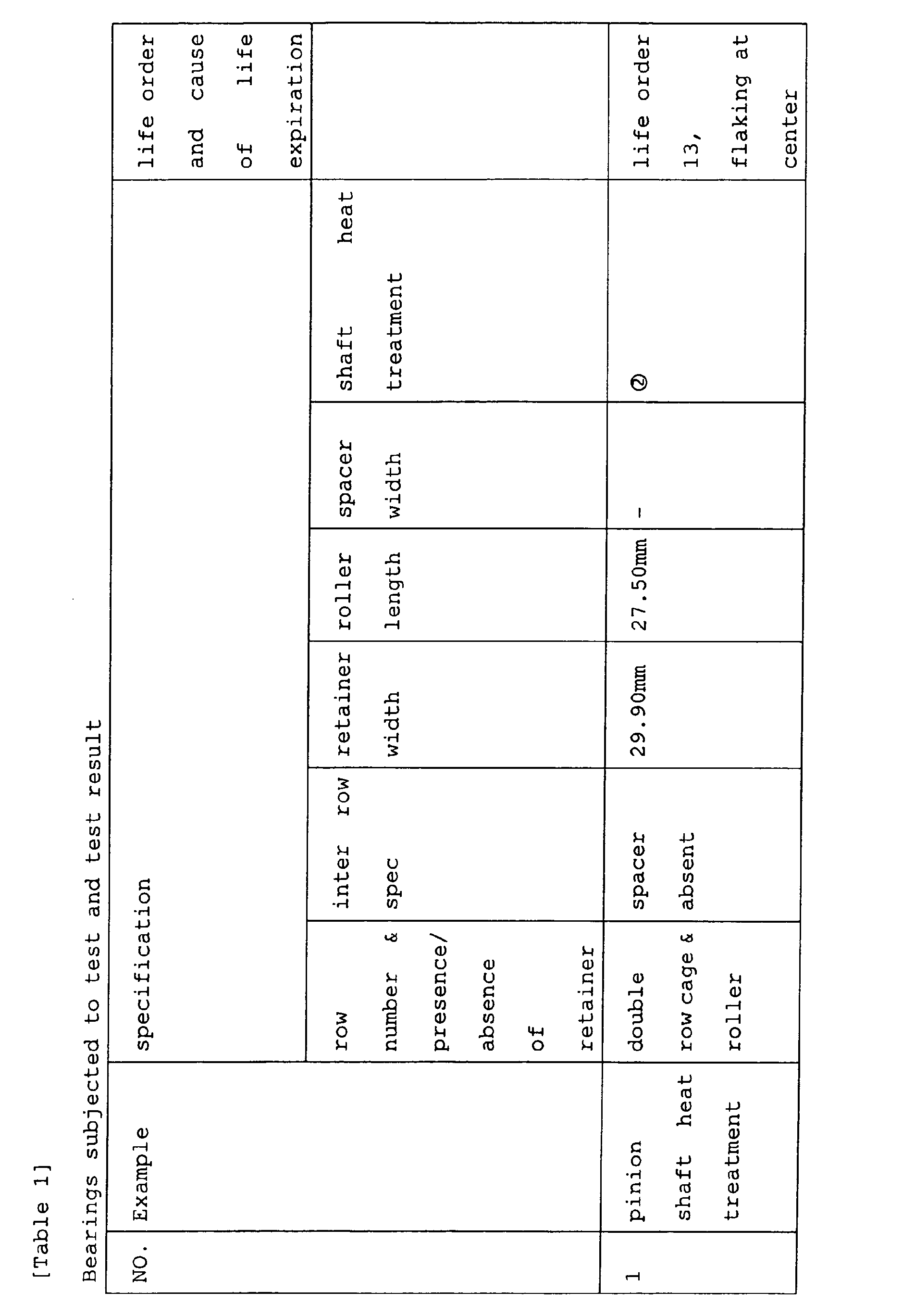
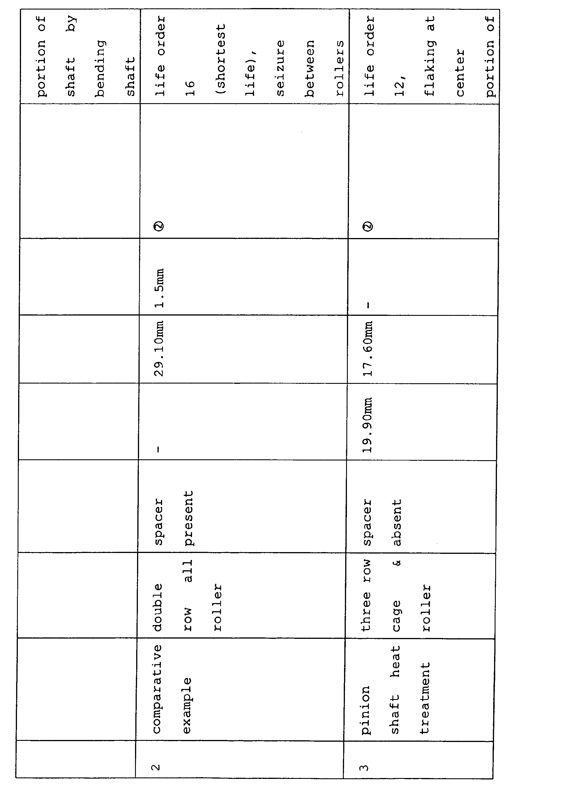
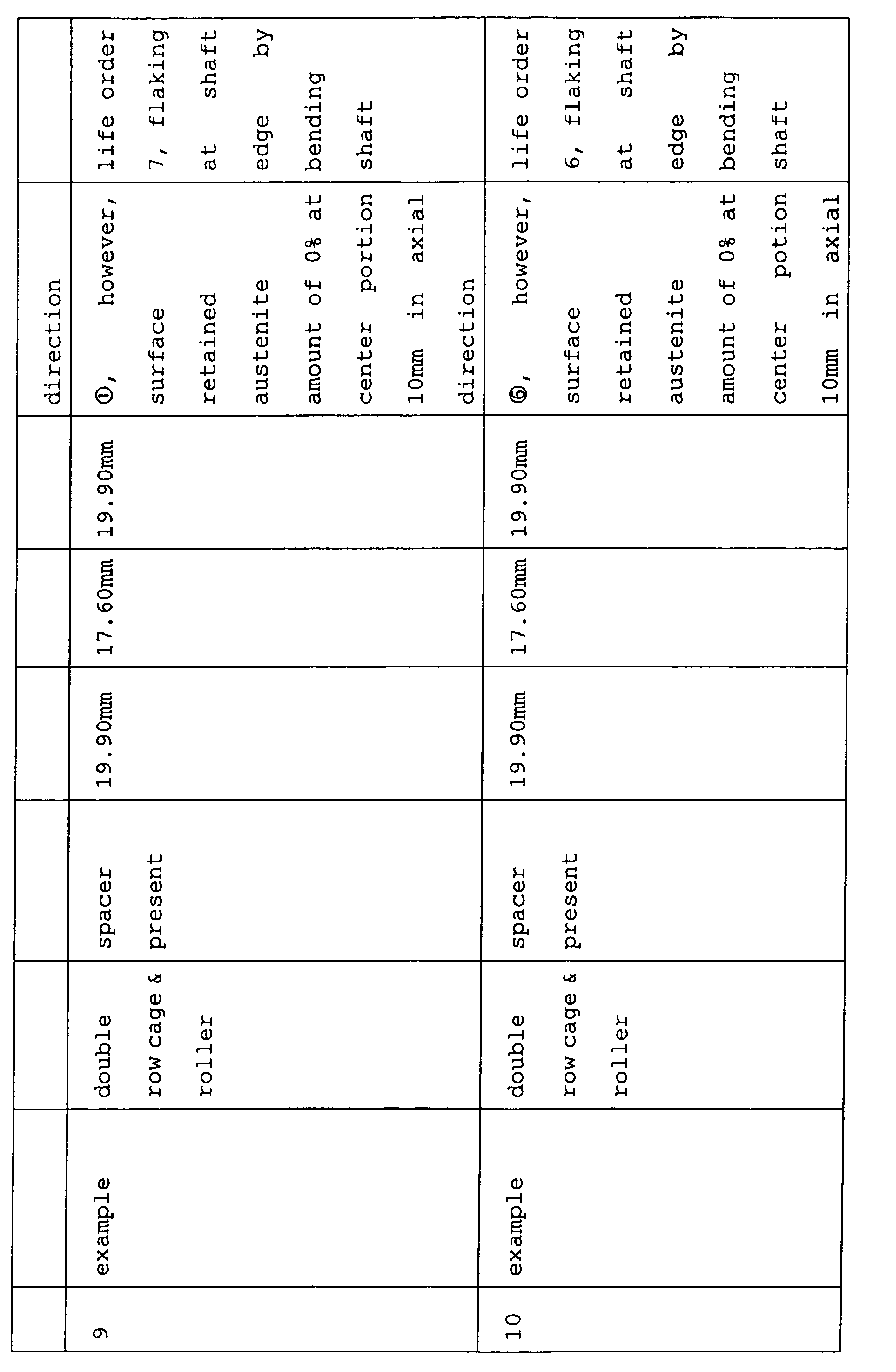
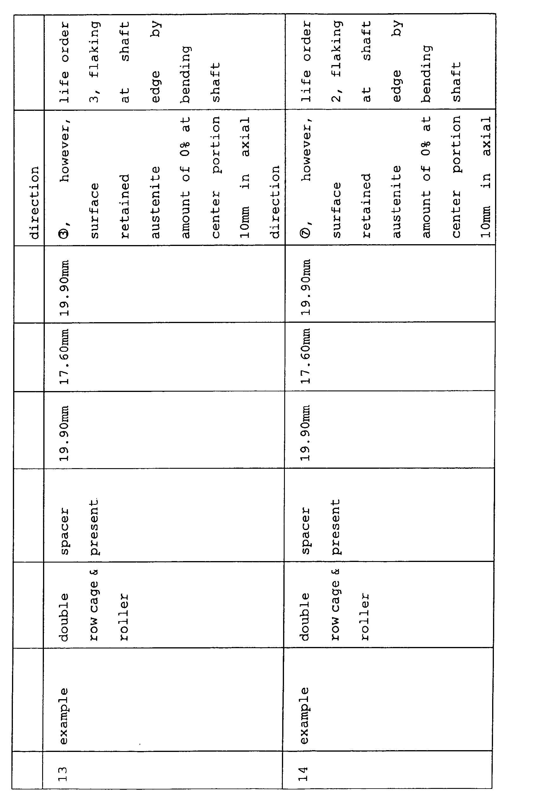
- a test result is shown in Table 1. Further, Table 2 shows compositions of materials of the pinion shaft used.
- a compressive residual stress at a surface layer of a track face of a pinion shaft used in pinion shaft heat treatments and examples 6, 7, 8 is about 300 MPa and a compressive residual stress of a surface layer at a track face used in comparative example 2 is 0 MPa.
- Chemical compositions of steels used kind of steel C% Si% Mn% Cr% SUJ2 0.98 0.24 0.40 1.40 SUJ3 0.97 0.45 1.01 0.99 SK5 0.81 0.22 0.35 0.09
- the life is prolonged owing to an effect of prolonging the life by chromium from the test result of example 7 using SUJ2 steel having a chromium concentration of 1.4 %.
- the test result of example 8 in which the surface retained austenite amount is reduced to 3 % at 10 mm of the shaft center portion covered by the spacer, that the reduction in the retained austenite amount at a nonrolling face reduces an amount of bending the pinion shaft and does not deteriorate the fatigue strength of a rolling face and therefore, the life is further prolonged.
- the nitrogen concentration of the surface is increased to 0.1% in comparison with that of example 9 and it is found that the life is further prolonged thereby.
- the life differs among examples 10 through 13 because the lowest hardness of the pinion shaft differs, showing that it is preferable that the lowest hardness of the shaft is equal to or larger than Hv 300, preferably, equal to or larger than Hv 350, further preferably, equal to or larger than Hv 400.
- a material is changed from SUJ2 to SUJ3 in contrast to example 13, it is found from the test result that since the silicon concentration is increased, the stability of the retained austenite structure is increased, the shaft is made to be difficult to bend and therefore, there is achieved an effect of prolonging the life.
- example 17 in contrast to example 16, the spacer material is changed from steel (STKM 17C hardened steel) to 46 nylon including 15 % of glass fiber and therefore, sliding friction with the retainer is reduced and the life is prolonged.
- example 18 in contrast to example 17, the compressive residual stress at the surface layer of the track face of the shaft is increased and therefore, the life is further prolonged.
- Figs.1A to 1C illustrate sectional views of a radial needle-like roller bearing 50' having a single row of rollers 51 arranged between a pinion shaft C and a pinion gear P1
- Fig. 1A shows a no load state
- Fig.1B shows a state of elastically deforming the pinion shaft in accordance with a load
- Fig.1C shows a state of plastically deforming the pinion shaft in addition to the elastic deformation in accordance with the load.
- Figs.2A to 2C illustrate sectional views of a radial needle-like roller bearing 50 having double rows of rollers 51, 51, retainers 52, 52 and a spacer 53 arranged between the pinion shaft C and the pinion gear P1
- Fig.2A shows a no load state
- Fig.2B shows a state of elastically deforming the pinion shaft in accordance with the load
- Fig. 2C shows a state of plastically deforming the pinion shaft in addition to the elastic deformation in accordance with a load.
- Such a spacer 53 is not for guiding the roller (roller) 51 but functions not to move the rolling roller (roller) 51 to the center portion in the axial direction of the shaft maximizing to bend the shaft and it is preferable that a width in an axis line direction thereof is equal to or larger than a length of the rollers at the double side rows interposing the spacer 53.
- bending of the shaft is not as large as that at the center portion and therefore, the roller (roller) is not hampered from being rolled smoothly.
- the retained austenite structure is not present at a center portion in a diameter direction over a total of the pinion shaft. It is important that further preferably, an amount of retained austenite at a surface of a center portion in an axial line direction of the pinion shaft at which the roller (roller) not rolled is smaller than those at the double side row portions at which the roller (roller) is rolled, most preferably, 0 %. Further, in order to achieve (2), it is effective that the retained austenite structure is stabilized and a rate of disintegrating the retained austenite structure is retarded by that amount.
- a nitrogen concentration of a surface of a hardened portion of a surface of the shaft is equal to or larger than 0.05 % or use a steel including silicon (Si) equal to or larger than 0.4 % as the material.
- the nitrogen concentration and the silicon concentration are respectively equal to or smaller than 0.5 % and equal to or smaller than 0.8 % in order to prevent crack in high frequency quenching.
- the lowest hardness of the pinion shaft (which is generally a hardness at a center portion in a diameter direction of the shaft) is equal to or larger than Hv 300, preferably, equal to or larger than Hv 350 and further preferably equal to or larger than Hv 400.
- a chromium concentration of the material (steel) is made to be equal to or larger than 0.9 %.
- the chromium concentration exceeds 1.8 %, a rate of dissolving a carbide in high frequency quenching is frequently retarded, hardness becomes nonuniform and therefore, it is preferable to set the chromium concentration to be equal to or smaller than 1.8 %.
- presence of the retained austenite structure is to be avoided at the center portion in the diameter direction of the shaft.
- a position of an oil outlet hole (hereinafter, written as oil hole) present in the surface of the shaft is important in view of supplying the lubricant to a total of the rolling face of the bearing.
- the pinion gear of the planetary gear mechanism is used in a field of a centrifugal force and therefore, the lubricant coming out from the oil hole is liable to flow in the direction of the centrifugal force and there is a concern of bringing about a state in which oil is not supplied to a portion of the rolling face. It is agitation of the lubricant by rotating the roller (roller) or the retainer to improve the situation, with regard to the position of the oil hole, it is most preferable that the lubricant coming out from the oil hole is disposed at a surface of the shaft at which the roller (roller) is rolled, and it is necessary that a portion thereof is included at least on the surface of the shaft covered by the retainer. Further, in the specification, “%” signifies “volume %” in the case of the retained austenite amount and signifies "weight %" in the case of a concentration of a chemical element.
- the spacer is rotated at a rotational speed substantially the same as that of the pinion gear
- retainers at the double side rows are rotated at a rotational speed slower than that of the pinion gear and therefore, a reduction in a sliding friction resistance between the spacer and the retainer amounts to a reduction in a temperature rise and therefore, the reduction is effective in restraining flaking or seizure.
- the retainer since the bearing used in the planetary gear mechanism is normally accompanied by revolving movement, the retainer is applied with a large repeated stress by colliding with the roller (roller) and therefore, it is preferable that the retainer is made of a steel having a strength.
- the spacer is made of a resin, or when the spacer is made of a steel, a spacer coated with a phosphate coating is used to reduce a dynamic friction coefficient between the spacer and the retainer to reduce a temperature rise. Further, it is further preferable that the spacer is made of a resin from a view point of restraining the pinion shaft from being bent.
- the bearing used in the planetary gear mechanism is the radial needle bearing for rotating the outer lace (pinion gear)
- the inner lace (shaft) becomes the weakest portion and therefore, strengthening of the pinion shaft is regarded to amount to prolong the life of the bearing.
- the compressive residual stress of the surface layer portion becomes 500 through 1200 MPa
- the amount of retained austenite is set to 15 through 40 %.
- the compressive residual stress and the amount of retained austenite of the surface layer portion of the pinion shaft are rectified by measured values at 50 ⁇ m below the surface.
- the compressive residual stress is less than 500 MPa
- the effect of prolonging the life is inconsiderable, when hard shot by which the compressive residual stress exceeds 1200 MPa is carried out, a crack is present in the surface layer portion, and the lift is shortened.
- the amount of retained austenite is less than 15 %
- the effect of prolonging the life is inconsiderable, and when the amount exceeds 40 %, plastic bending of the pinion shaft is increased and therefore, the life is conversely shortened.
Landscapes
- Engineering & Computer Science (AREA)
- General Engineering & Computer Science (AREA)
- Mechanical Engineering (AREA)
- Manufacturing & Machinery (AREA)
- Rolling Contact Bearings (AREA)
- General Details Of Gearings (AREA)
- Heat Treatment Of Articles (AREA)
Abstract
Description
- The present invention relates to a radial needle-like roller bearing and a pinion shaft used in, for example, a planetary gear mechanism of a vehicular automatic transmission.
- A planetary gear mechanism is generally used in an automatic transmission mounted to a vehicle or the like. Meanwhile, in recent years, also an automatic transmission tends to be formed by multistages with an object of improving fuel cost. At the same time, a planetary gear mechanism referred to as so-to-speak Ravigneau type is tried to be used to form an automatic transmission of 4 speeds as a main stream currently by mutlistages of, for example, 5 speeds or 6 speeds to downsize the automatic transmission. The Ravigneau type planetary gear mechanism is combined with two planetary gear mechanisms commonly using a planetary gear and is described in, for example Patent Reference 1.
- Here, a characteristic of the Ravigneau type planetary gear type mechanism resides in that since a width in a axial line direction of the planetary gear commonly used is enlarged, a length in an axial line direction of a pinion shaft supporting the planetary gear relative to a diameter thereof is prolonged, that is, the pinion shaft becomes slender. Meanwhile, as shown by Patent Reference 2, as a rolling bearing for supporting a planetary gear in a general planetary gear mechanism, there is frequently used a radial needle-like roller bearing in which a needle-like roller is arranged as a rolling member between a pinion shaft serving also as an inner ring of the bearing and the planetary gear serving also as an outer ring of the bearing. However, although an such a needle-like roller bearing, there is generally used an all roller type which is not provided with a retainer in a background art, recently, there is a case of using a so-to-speak cage & roller type having a retainer for rotating the planetary gear at high speed. When a plurality or more of rows of rollers (rollers) are constituted by the all roller type, it is general to provide a guide ring for guiding end portions of the rollers (rollers) between the rows. In contrast thereto, according to the cage & roller type, even when a plurality or more of those of rollers (rollers) are constituted, it is general that the guide ring is not provided since the retainer guides the end faces of the rollers (rollers) .
- [Patent Reference 1] Japanese Utility Model Application Publication No. Hei4-126055
- [Patent Reference 2] Japanese Utility Model Application Publication No. Hei5-62729
-
- Here, in a planetary gear mechanism, a planetary gear is revolved to move and therefore, a centrifugal force operated to the planetary gear and a force of being brought in mesh with other gear elastically deform a pinion shaft. Although hardened steel is normally used for the pinion shaft, owing to a retained austenite structure inevitably present therein, in using the pinion shaft at a high temperature equal to or higher than 100 °C, the retained austenite structure is disintegrated to expand a volume thereof. When the pinion shaft is elastically deformed at 100 °C or higher, a rate of disintegrating the retained austenite structure at a portion of operating a tensile stress faster than at a portion of operating a compressive stress and therefore, generally, the remoter from the portion of the pinion shaft attached to a carrier, the more the plastically bending is brought about in a bow-like shape, and the higher the temperature of the shaft, the faster the speed of revolving the planetary gear, further, the slenderer and the longer the pinion shaft, the higher the torque loaded to the gear, the more the rate tends to increase.
- Particularly, when the Ravigneau type planetary gear mechanism disclosed in, for example, Patent Reference 1 is used for downsizing the planetary gear mechanism of a vehicular transmission of an automatic transmission or the like, there poses a problem that plastic bending of the long pinion is liable to be brought about since the shaft length is prolonged. When a sum of the plastic bending and elastic bending determined by loading conditions of the shaft which increases agingly is increased and a distance between the shaft and an inner diameter face of the pinion gear becomes smaller than a roller diameter, there poses a problem that the roller (roller) cannot smoothly be rolled and flaking is brought about at the shaft or the roller (roller).
- The invention is carried out in view of the above-described problems and it is an object thereof to provide a radial needle-like roller bearing and a pinion shaft capable of ensuring to smoothly roll a roller.
- According to the first aspect of the present invention, there is provided a radial needle-like roller bearing arranged between a pinion shaft and a pinion gear in a planetary gear mechanism of a vehicular automatic transmission, the radial needle-like roller bearing including: rollers arranged in double rows, a plurality of retainers for retaining the rollers of the respective rows, and a spacer arranged between the retainers contiguous to each other.
- According to the second aspect of the present invention, it is preferable that the pinion shaft is made of a steel and includes a surface hardened by quenching and a center portion which does not include a retained austenite structure, and the roller is rolled along a surface hardened by quenching.
- According to the third aspect of the present invention, it is preferable that an amount of retained austenite at an outer surface of the pinion shaft covered by the spacer is lower than an amount of retained austenite at the surface of the pinion shaft at which the roller is rolled.
- According to the forth aspect of the present invention, it is preferable that a nitrogen concentration of the surface of the pinion shaft is equal to or larger than 0.05 % and equal to or smaller than 0.5 %.
- According to the fifth aspect of the present invention, it is preferable that a material of the pinion shaft includes chromium equal to or larger than 0.9 % and equal to or smaller than 1.8 %.
- According to the sixth aspect of the present invention, it is preferable that the material of the pinion shaft includes silicon equal to or larger than 0.4 % and equal to or smaller than 0.8 %.
- According to the seventh aspect of the present invention, it is preferable that a hardness of the pinion shaft is equal to or larger than Hv 300.
- According to the eighth aspect of the present invention, it is preferable that the pinion shaft is provided with a hole for supplying a lubricant at the outer surface covered by the retainer.
- According to the ninth aspect of the present invention, it is preferable that the spacer is made of a resin or made of a steel coated with a phosphate coating at a surface thereof.
- According to the tenth aspect of the present invention, it is preferable that the pinion shaft is made of a steel, and a compressive residual stress of a surface layer portion is set to 500 through 1200 MPa and the amount of retained austenite is set to 15 through 40 %.
- According to the eleventh aspect of the present invention, there is provided a pinion shaft used in the radial needle-like roller bearing according to any one of the first aspect through the tenth aspect.
- According to the twelfth aspect of the present invention, there is provided a radial needle-like roller bearing arranged between a pinion shaft and a pinion gear in a planetary gear mechanism of a vehicular automatic transmission,
the radial needle-like roller bearing including: - rollers arranged in double rows,
- a plurality of retainers for retaining the rollers of the respective rows, and
- a spacer arranged between the retainers contiguous to each other, wherein
- the pinion shaft is made of a steel, and includes a surface hardened by quenching and a center portion which does not include a retained austenite structure,
- the roller is rolled along a surface hardened by quenching,
- a nitrogen concentration of the surface of the pinion shaft is equal to or larger than 0.05 % and equal to or smaller than 0.5 %,
- the material of the pinion shaft includes chromium equal to or larger than 0.9 % and equal to or smaller than 1.8 %,
- the hardness of the pinion shaft is equal to or larger than Hv 300,
- the spacer is made of a resin or made of a steel coated with a phosphate coating at a surface thereof, and
- a compressive residual stress of a surface layer portion is set to 500 through 1200 MPa, and the amount of retained austenite is set to 15 through 40 %.
-
- According to the thirteenth aspect of the present invention, there is provided a radial needle-like roller bearing arranged between a pinion shaft and a pinion gear in a planetary gear mechanism of a vehicular automatic transmission,
the radial needle-like roller bearing including: - rollers arranged in double rows,
- a plurality of retainers for retaining the rollers of the respective rows,
- a spacer arranged between the retainers contiguous to each other, wherein
- the pinion shaft is made of a steel, and includes a surface hardened by quenching and a center portion which does not include a retained austenite structure,
- the roller is rolled along a surface hardened by quenching,
- a nitrogen concentration of the surface of the pinion shaft is equal to or larger than 0.05 % and equal to or smaller than 0.5 %,
- the material of the pinion shaft includes chromium equal to or larger than 0.9 % and equal to or smaller than 1.8 %,
- the material of the pinion shaft includes silicon equal to or larger than 0.4 % and equal to or smaller than 0.8 %,
- the hardness of the pinion shaft is equal to or larger than Hv 300,
- the spacer is made of a resin or made of a steel coated with a phosphate coating at a surface thereof, and
- a compressive residual stress of a surface layer portion is set to 500 through 1200 MPa, and the amount of retained austenite is set to 15 through 40 %.
-
-
- Figs.1A to 1C illustrate sectional views of a radial needle-like roller bearing 50 having a single row of rollers arranged between a pinion shaft C and a pinion gear P1.
- Figs.2A to 2C illustrate sectional views of the radial needle-like roller bearing 50 having double rows of rollers arranged between the pinion shaft C and the pinion gear P1.
- Fig.3 is a partial sectional view of an automatic transmission 1 of a vehicle including a dial needle-like roller bearing according an embodiment.
- Fig.4 is a sectional view showing a periphery of a pinion shaft of a planetary gear set according to the embodiment.
- Fig.5 is a sectional view of a test apparatus.
-
- A detailed explanation will be given of an embodiment of the invention in reference to the drawings as follows. Fig.3 is a sectional view showing a portion of an automatic transmission of a vehicle including a radial needle-like roller bearing according to the embodiment.
- In Fig.3, at inside of a
case 10, aninput shaft 11 constituting an input member for transmitting rotation of an output of a turbine of a torque converter, not illustrated, to a planetary gear set 12 is arranged on a side of afront sun gear 13 of the planetary gear set 12. Further, acounter drive gear 14 is arranged on a side of arear sun gear 15 of the planetary gear set 12 by interposing a rear wall of thecase 10. Further, an inner peripheral side of the planetary gear set 12 is arranged with asun gear shaft 20 constituting a supporting shaft of the planetary gear set 12, according to the embodiment, the shaft is integrated with therear sun gear 15 and is extended to penetrate the planetary gear set 12 and thecounter drive gear 14. - The
input shaft 11 is supported by thecase 10 and connected to the turbine of the torque converter,respective clutches input shaft 11, a vicinity of a front end portion thereof is supported by a hollow stator shaft 19 fixed to a front wall of thecase 10 constituted by an oil pump cover via a bush, further, a vicinity of a rear end portion thereof is supported via a needle bearing, a front end thereof is connected to a turbine hub (not illustrated) by spline engagement, and a rear end thereof is connected to an innerperipheral side member 21 of a hydraulic servo cylinder on sides of drums of therespective clutches - According to the
sun gear 20, an end portion thereof on one side is connected to theinput shaft 11 via the clutch 18 and the first one way clutch OC1, and an end portion thereof on other side is connected to thecase 10 via abrake 22 on an outer side penetrating thecounter drive gear 14. In details, according to thesun gear 20, a front end thereof is supported by a recess portion at a rear end of theinput shaft 11 via a bush, a vicinity of a rear end portion thereof is supported by an inner periphery of a shaft portion of aring gear flange 23 via a bush, and is finally supported by the rear wall of thecase 10 via a boss portion and a roller bearing of thecounter drive gear 10 fitted to an outer periphery thereof. Further, a side of a front end portion of thesun gear 20 is connected to a side of a hub 24 of the clutch 18 by spline engagement. Further, a rear end of thesun gear shaft 20 is connected to a side of ahub 25 by spline engagement. - According to the planetary gear set 12, by supporting the
front sun gear 13 and a carrier Q by thesun gear shaft 20 respectively via bushes and fixing aring gear 26 by thecounter drive gear 14 connected to the member by spline engagement via thering gear flange 23 connected thereto by spline engagement, as a result, the planetary gear set 22 is supported by the rear wall ofcase 10 via aball bearing 27. Thefront sun gear 13 of the planetary gear set 12 is connected to a side of ahub 28 of the clutch 17, the carrier Q is connected in parallel with ahub 29 of the clutch 16, ahub 31 of abrake 30 and an inner lace of a second one way clutch OC2. - In the gear train, the clutch 17 connecting the
input shaft 11 to thefront sun gear 13, the clutch 16 connecting theinput shaft 11 to the clutch 17 and the carrier Q connecting theinput shaft 11 to therear sun gear 17, respectively, hydraulic servos and friction members of the respective clutches are summarizingly arranged at an outer periphery of a portion of connecting theinput shaft 11 and thesun gear shaft 20. First, the clutch 17 is constituted by the innerperipheral side member 21 rotatably fitted to an outer periphery of aboss portion 32 extended from the oil pump fixed to an oil bump body constituting the front wall of thecase 10 by a bolt, a hydraulic servo fitted with apiston 34 serving also as a drum of the clutch 17 to prevent rotation thereof to an inner side surrounded by adrum 33 an inner peripheral side of which is fixed thereto, and afriction member 40 connected to an outer periphery of ahub 28 arranged by connecting an inner periphery side thereof to an inner side of an inner periphery of a front end of thedrum 33 and thefront sun gear 13 respectively by spline engagement. - Next, the clutch 18 includes the
drum 34 slidably fitted to insert into the innerperipheral side member 21 to serve also as the piston of the clutch 17, and apiston 35 fitted to insert into an inner side of a cylinder surrounded by the innerperipheral side member 21 and thedrum 34, and is constituted by a hydraulic servo having a chamber of canceling a centrifugal hydraulic pressure on a rear side of thepiston 35, and afriction member 36 respectively connected to an inner periphery of a front end of thedrum 34 and an outer periphery of the hub 24 an inner peripheral side of which is connected to theinput shaft 11 at a further inner periphery thereof by spline engagement. Further, the hub 24 of the clutch 18 is fixed with an outer lace of the first one way clutch OC1. - The clutch 16 is constructed by a constitution of constituting a piston by a
drum 33 of the clutch 17 and connecting thepiston 37 fitted to cover the piston conversely to adrum 38, and is constituted by a hydraulic servo having a chamber of canceling a centrifugal hydraulic pressure, and afriction member 39 connected to an outer periphery of ahub 29 connected to an inner lace of the second one way clutch OC2 fixed to the carrier Q of the planetary gear set 12 by a rivet and an inner periphery of thedrum 38 by spline engagement. - In the hydraulic servos of the respective clutches arranged summarizingly in this way, the
member 33 serving also as the innerperiphery side member 21 common to the respective clutches and the drum of the clutch 17 and the piston of the clutch 16 is constituted by a member unmovable in an axial direction, and both of thedrum 34 and thepiston 35 of the clutch 18 are constituted by members movable in the axial direction. Therefore, the clutch 17 pinches thefriction member 40 between thedrum 33 of its own and thedrum 34 of the clutch 18 to engage by supplying a servo hydraulic pressure from an oil path of theboss portion 32, the clutch 18 pinches thefriction member 36 between the drum of its own serving also as thepiston 34 of the clutch 17 and thepiston 35 by pressing thepiston 35 of its own by being exerted with a reaction force at thedrum 33 of the clutch 17, and the clutch 16 pinches thefriction member 39 by moving forward thedrum 38 of its own to thedrum 33 of the clutch 17 in the axial direction therebetween. - Next, the
brake 30 is constituted by the hydraulic servo included in the rear wall of thecase 10 and afriction member 42 engaged with thehub 31 extended from an inner lace of the second one way clutch OC2 and the peripheral wall of thecase 10 by a spline, and thefriction member 42 is arranged on an outer side in a diameter direction of thering gear 26 of the planetary gear set 12. Further, the second one way clutch OC2 arranged in parallel therewith is arranged substantially at a center portion in an axial direction of an outer side in a diameter direction of the planetary gear set 12 by connecting the inner lace to the carrier Q of the planetary gear set 12 as described above and engaging the outer lace to the outer wall of thecase 10 by a spline. - The
brake 22 is arranged on an outer side of the rear wall of thecase 10, and is constituted by acover 10a covering a counter gear pair arranged there, afriction member 43 arranged on a rear side of the counter gear pair engaged with thehub 25 fixed to a rearmost portion of thesun gear 20 by a spline, and a hydraulic servo included in the rear wall of thecase 10. - When a first speed (1st) is selected in the gear train, rotation from the
input shaft 11 is inputted to thefront sun gear 13 via the clutch 17, a reaction force is exerted to the carrier Q locked by engaging with the second one way clutch OC2, rotation at a reduced speed of a maximum reduction ratio outputted to aring gear 26 is transmitted to a ring gear of a sub speed changing portion via the counter gear pair and is transmitted to a drive wheel of a vehicle from a differential apparatus, not illustrated. - Next, according to a second speed (2nd), rotation is inputted also from the
input shaft 11 to thefront sun gear 13 via the clutch 17, a reaction force is exerted to therear sun gear 15 locked by engaging with thebrake 22, and rotation at a reduced speed of thering gear 26 is outputted. Rotation is inputted to the ring gear of the sub speed changing portion and is transmitted to the drive wheel of the vehicle from the differential apparatus, not illustrated. - Further, a third speed (3rd) is achieved by engaging a clutch on a side of a sub shaft portion by operating similar to the second speed with regard to the side of the main shaft portion. In this case, rotation from the third speed changing portion is transmitted to the drive wheel of the vehicle from the differential apparatus, not illustrated, via the planetary gear in a directly connected state by engaging the clutch.
- Further, according to a fourth speed (4th), both of the planetary gear set 12 on the side of the main speed changing portion and the planetary gear on the side of the sub speed changing portion are brought into a directly connected state, and rotation inputted from the
input shaft 11 is transmitted to the drive wheel of the vehicle from the differential apparatus, not illustrated, as it is by dispensing with speed reduction by the counter gear pair. - Fig.4 is a sectional view showing a periphery of the pinion shaft of the planetary gear set according to the embodiment. As shown by Fig.4, the needle-
like roller bearing 50 includes therollers retainers rollers spacer 53 arranged between theretainers retainers like roller bearing 50 is lubricated by a lubricant supplied from outside of the pinion shaft C via the cap hole Ca and the diameter holes Cb, Cb. Further, it is preferable that a width of thespacer 53 is equal to or larger than a length of therollers spacer 53 and it is preferable that an outer diameter thereof is equal to that of theretainers spacer 53 and the pinion shaft C and the pinion gear P1, thespacer 53 and the pinion shaft C are not slid relative to each other. - Next, an explanation will be given of a test which is carried out by the inventors. Fig.5 is a sectional view of a test apparatus used in such a test. Supporting
portions base 101 above a level block. The supportingportion 102 on the left side is fitted with aholder 104 in a cylindrical shape and a sungear rotating shaft 105 is rotatably supported by theholder 14 by a bearing. A sung gear S is formed at a right end of the sunggear rotating shaft 105. - The supporting
portion 103 on the right side is fitted with aholder 106 in a cylindrical shape and acarrier rotating shaft 107 is rotatably supported by theholder 104 by a bearing. The carrier Q is attached to a right end of thecarrier rotating shaft 107. Theholder 106 is attached with alubricant delivering apparatus 108 and a predetermined amount of a lubricant is supplied to the needle-like roller bearing 50 therefrom via apath 107a provided at an inner portion of thecarrier rotating shaft 107, a path Qa formed at an inner portion of the carrier Q, the cap hole Ca and the diameter hole Cb of the pinion shaft C. The pinion shaft C rotatably supports the long pinion P1 via the needle-like roller bearing 50. - The test is carried out by setting comparative examples and examples to the test apparatus shown in Fig.5. Test conditions are as follows.
-
- pinion revolving speed: 8000 min-1
- pinion rotating speed: 10000 min-1
- pinion revolving radius: 45 mm
- pinion weight: 274 g
- test temperature: 120 °C
- lubricant amount: 33 cc/min
- pinion shaft diameter: 14.00 mm
- position of pinion shaft diameter hole (Cb): one piece at a center in an axial direction, 180° relative to a sun gear direction in a circumferential direction
- heat treatment of pinion shaft: any of following heat
treatments (1) through (8)
- (1) high frequency quenching of JIS SUJ 2 steel (hardness: Hv 210) by effective hardness layer depth (depth of Hv 550 or more) of 1 mm (surface retained austenite amount: 10 %, core portion retained austenite amount: 0 %)
- (2) completely quench JIS SUJ 2 steel to core portion (retained austenite amount: uniformly 10 % as a whole)
- (3) subject JIS SUJ 2 steel to nitriding treatment at 840 °C, core portion hardness is adjusted to Hv 400 by tempering, thereafter, high frequency quenching (surface retained austenite amount: 15 %, core portion retained austenite amount: 0 %, surface nitrogen concentration: 0.1%, effective hardened layer depth: 1 mm)
- (4) subject JIS SUJ 2 steel to nitriding treatment at 840 °C, core portion hardness is adjusted to Hv 350 by tempering, thereafter, high frequency quenching (surface retained austenite amount: 15 %, core portion retained austenite amount: 0 %, surface nitrogen concentration: 0.1 %, effective hardened layer depth: 1 mm)
- (5) subject JIS SUJ 2 steel to nitriding treatment at 840 °C, core portion hardness is adjusted to Hv 300 by tempering, thereafter, high frequency quenching (surface retained austenite amount: 15 %, core portion retained austenite amount: 0 %, surface nitrogen concentration: 0.1 %, effective hardened layer depth: 1 mm)
- (6) subject JIS SUJ 2 steel to nitriding treatment at 840 °C, core portion hardness is adjusted to Hv 210 by tempering, thereafter, high frequency quenching (surface retained austenite amount: 15 %, core portion retained austenite amount: 0 %, surface nitrogen concentration: 0.1 %, effective hardened layer depth: 1 mm)
- (7) subject JIS SUJ 3 steel to nitriding treatment at 840 °C, core portion hardness is adjusted to Hv 400 by tempering, thereafter, high frequency quenching (surface retained austenite amount: 15 %, core portion retained austenite amount: 0 %, surface nitrogen concentration: 0.1 %, effective hardened layer depth: 1 mm)
- (8) high frequency quenching of JIS SK 5 steel (hardness Hv 210) by effective hardened layer depth (depth of Hv 550 or more) of 1 mm (surface retained austenite amount: 10 %, core portion retained austenite amount: 0 %)
- pinion inner diameter: 19.03 mm
- pinion width: 60.00 mm
- needle-like roller diameter: 2.5 mm
-
- Further, a roller length is determined pertinently in accordance with a number of rows. A test result is shown in Table 1. Further, Table 2 shows compositions of materials of the pinion shaft used.





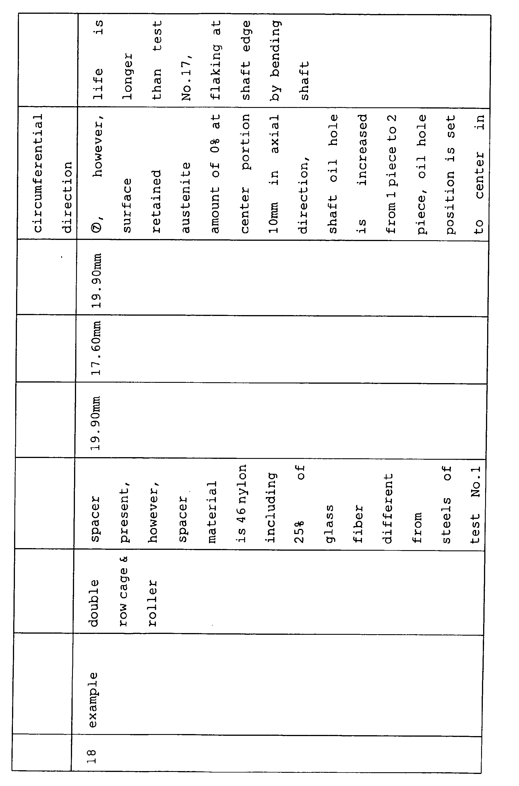

- Further, a compressive residual stress at a surface layer of a track face of a pinion shaft used in pinion shaft heat treatments and examples 6, 7, 8 is about 300 MPa and a compressive residual stress of a surface layer at a track face used in comparative example 2 is 0 MPa.
Chemical compositions of steels used kind of steel C% Si% Mn% Cr% SUJ2 0.98 0.24 0.40 1.40 SUJ3 0.97 0.45 1.01 0.99 SK5 0.81 0.22 0.35 0.09 - Investigating on the test result, from test result of comparative examples 2, 4, 5, in all roller (without retainer) type, seizure is brought about at high speed rotation and it is found that the all roller type is not suitable for high speed rotation. On the other hand, from the test result of comparative examples 1, 3, it is found that there poses a problem that although by constituting a cage & roller (having retainer) type, although seizure can be prevented, flaking is brought about at a shaft center portion by reducing a radial clearance of the shaft center portion caused by bending the pinion shaft. In contrast thereto, from the test result of example 6, it is found that when the roller is restricted not to roll a surrounding of the shaft center portion, the roller becomes insensitive to bending of the shaft and the life is prolonged. Further, the position of flaking in this case is not at the shaft center portion but edge portions on sides of shaft ends of shaft rolling faces of the double side rows. The smaller the bending of the shaft, the smaller the contact face pressure of the edge portion.
- Further, from the test result of example 15, it is found that when the pinion shaft made of high frequency quenched SK5 steel nullifying the retained austenite amount at the center portion in the diameter direction of the pinion shaft is used, the bending of the shaft is restrained and therefore, touch of the edge is alleviated and the life is further prolonged. In this way, it is effective to provide the spacer having a length equal to or longer than those of the rollers (rollers) at the double side rows and combined to use the shaft having the core portion retained austenite amount of 0 %.
- It is found that the life is prolonged owing to an effect of prolonging the life by chromium from the test result of example 7 using SUJ2 steel having a chromium concentration of 1.4 %. Further, it is found that the test result of example 8 in which the surface retained austenite amount is reduced to 3 % at 10 mm of the shaft center portion covered by the spacer, that the reduction in the retained austenite amount at a nonrolling face reduces an amount of bending the pinion shaft and does not deteriorate the fatigue strength of a rolling face and therefore, the life is further prolonged. Further, it is found from the test result of example 9 reducing the surface retained austenite amount to 0 % at 10 mm of the shaft center portion covered by the spacer that the lift is further prolonged. In examples 10 through 13, the nitrogen concentration of the surface is increased to 0.1% in comparison with that of example 9 and it is found that the life is further prolonged thereby. The life differs among examples 10 through 13 because the lowest hardness of the pinion shaft differs, showing that it is preferable that the lowest hardness of the shaft is equal to or larger than Hv 300, preferably, equal to or larger than Hv 350, further preferably, equal to or larger than Hv 400. Although in examples 14, a material is changed from SUJ2 to SUJ3 in contrast to example 13, it is found from the test result that since the silicon concentration is increased, the stability of the retained austenite structure is increased, the shaft is made to be difficult to bend and therefore, there is achieved an effect of prolonging the life. In the example 16, in contrast to example 15, the position of the oil hole is changed from the position covered by the spacer to the position directed to the sun gear at the center of the double side rows and therefore, it is found from the test result that the lubricant is agitated in the bearing, much lubricant is supplied to the rolling face and therefore, there is achieved an effect of prolonging the life.
- Further, in example 17, in contrast to example 16, the spacer material is changed from steel (STKM 17C hardened steel) to 46 nylon including 15 % of glass fiber and therefore, sliding friction with the retainer is reduced and the life is prolonged. In example 18, in contrast to example 17, the compressive residual stress at the surface layer of the track face of the shaft is increased and therefore, the life is further prolonged.
- Although an explanation is given of the invention in reference to the examples as described above, the invention is not to be interpreted to be limited to the above-described embodiment but can naturally be modified or improved pertinently. The invention is not limited to the Ravigneau type planetary gear mechanism but is applicable to a needle-like roller bearing and a pinion shaft used in a planetary gear mechanism of other type.
- An explanation will be given of operation and effect of the invention in reference to the drawings. Figs.1A to 1C illustrate sectional views of a radial needle-like roller bearing 50' having a single row of
rollers 51 arranged between a pinion shaft C and a pinion gear P1, Fig. 1A shows a no load state, Fig.1B shows a state of elastically deforming the pinion shaft in accordance with a load, and Fig.1C shows a state of plastically deforming the pinion shaft in addition to the elastic deformation in accordance with the load. Figs.2A to 2C illustrate sectional views of a radial needle-like roller bearing 50 having double rows ofrollers retainers spacer 53 arranged between the pinion shaft C and the pinion gear P1, Fig.2A shows a no load state, Fig.2B shows a state of elastically deforming the pinion shaft in accordance with the load, and Fig. 2C shows a state of plastically deforming the pinion shaft in addition to the elastic deformation in accordance with a load. - As shown by Fig.1C, when a sum of elastic bending and plastic bending of the pinion shaft (hereinafter, described as an amount of bending shaft) is increased and a distance between the pinion shaft and an inner diameter face of the pinion gear becomes smaller than a diameter of the roller, the roller (roller) cannot smoothly be rolled. In contrast thereto, the inventors have derived that the above-described problem can be resolved,
- (1) by preventing a roller (roller) from being rolled at a center portion in an axial direction of the shaft maximizing an amount of bending the shaft , or
- (2) by reducing the amount of bending the shaft.
-
- Based on such a derivation, according to the invention, in order to achieve the object of (1), there is adopted a constitution of arranging the
spacer 53 at a center portion of the shaft and arranging theretainers 52 and the rollers 51 (cage & roller) at the double sides thereof. Such aspacer 53 is not for guiding the roller (roller) 51 but functions not to move the rolling roller (roller) 51 to the center portion in the axial direction of the shaft maximizing to bend the shaft and it is preferable that a width in an axis line direction thereof is equal to or larger than a length of the rollers at the double side rows interposing thespacer 53. At the double side rows, bending of the shaft is not as large as that at the center portion and therefore, the roller (roller) is not hampered from being rolled smoothly. - Meanwhile, in order to achieve the object of (2), it is necessary that the retained austenite structure is not present at a center portion in a diameter direction over a total of the pinion shaft. It is important that further preferably, an amount of retained austenite at a surface of a center portion in an axial line direction of the pinion shaft at which the roller (roller) not rolled is smaller than those at the double side row portions at which the roller (roller) is rolled, most preferably, 0 %. Further, in order to achieve (2), it is effective that the retained austenite structure is stabilized and a rate of disintegrating the retained austenite structure is retarded by that amount. For that purpose, it is preferable to set a nitrogen concentration of a surface of a hardened portion of a surface of the shaft to be equal to or larger than 0.05 % or use a steel including silicon (Si) equal to or larger than 0.4 % as the material.
- Further, it is preferable that the nitrogen concentration and the silicon concentration are respectively equal to or smaller than 0.5 % and equal to or smaller than 0.8 % in order to prevent crack in high frequency quenching. Further, in order to restrain plastic bending of the pinion shaft, it is important that the lowest hardness of the pinion shaft (which is generally a hardness at a center portion in a diameter direction of the shaft) is equal to or larger than Hv 300, preferably, equal to or larger than Hv 350 and further preferably equal to or larger than Hv 400. Further, in order to prolong rolling fatigue life, it is preferable that a chromium concentration of the material (steel) is made to be equal to or larger than 0.9 %. However, when the chromium concentration exceeds 1.8 %, a rate of dissolving a carbide in high frequency quenching is frequently retarded, hardness becomes nonuniform and therefore, it is preferable to set the chromium concentration to be equal to or smaller than 1.8 %. In any of the above-described cases, presence of the retained austenite structure is to be avoided at the center portion in the diameter direction of the shaft. A position of an oil outlet hole (hereinafter, written as oil hole) present in the surface of the shaft is important in view of supplying the lubricant to a total of the rolling face of the bearing. As described above, the pinion gear of the planetary gear mechanism is used in a field of a centrifugal force and therefore, the lubricant coming out from the oil hole is liable to flow in the direction of the centrifugal force and there is a concern of bringing about a state in which oil is not supplied to a portion of the rolling face. It is agitation of the lubricant by rotating the roller (roller) or the retainer to improve the situation, with regard to the position of the oil hole, it is most preferable that the lubricant coming out from the oil hole is disposed at a surface of the shaft at which the roller (roller) is rolled, and it is necessary that a portion thereof is included at least on the surface of the shaft covered by the retainer. Further, in the specification, "%" signifies "volume %" in the case of the retained austenite amount and signifies "weight %" in the case of a concentration of a chemical element.
- Whereas the spacer is rotated at a rotational speed substantially the same as that of the pinion gear, retainers at the double side rows are rotated at a rotational speed slower than that of the pinion gear and therefore, a reduction in a sliding friction resistance between the spacer and the retainer amounts to a reduction in a temperature rise and therefore, the reduction is effective in restraining flaking or seizure. On the other hand, since the bearing used in the planetary gear mechanism is normally accompanied by revolving movement, the retainer is applied with a large repeated stress by colliding with the roller (roller) and therefore, it is preferable that the retainer is made of a steel having a strength. Hence, it is effective that the spacer is made of a resin, or when the spacer is made of a steel, a spacer coated with a phosphate coating is used to reduce a dynamic friction coefficient between the spacer and the retainer to reduce a temperature rise. Further, it is further preferable that the spacer is made of a resin from a view point of restraining the pinion shaft from being bent.
- Since the bearing used in the planetary gear mechanism is the radial needle bearing for rotating the outer lace (pinion gear), the inner lace (shaft) becomes the weakest portion and therefore, strengthening of the pinion shaft is regarded to amount to prolong the life of the bearing. For example, it is effective for prolonging the life that the pinion shaft is subjected to shot peeing, the compressive residual stress of the surface layer portion becomes 500 through 1200 MPa, and the amount of retained austenite is set to 15 through 40 %. The compressive residual stress and the amount of retained austenite of the surface layer portion of the pinion shaft are rectified by measured values at 50 µm below the surface. When the compressive residual stress is less than 500 MPa, the effect of prolonging the life is inconsiderable, when hard shot by which the compressive residual stress exceeds 1200 MPa is carried out, a crack is present in the surface layer portion, and the lift is shortened. Further, when the amount of retained austenite is less than 15 %, the effect of prolonging the life is inconsiderable, and when the amount exceeds 40 %, plastic bending of the pinion shaft is increased and therefore, the life is conversely shortened.
Claims (13)
- A radial needle-like roller bearing arranged between a pinion shaft and a pinion gear in a planetary gear mechanism of a vehicular automatic transmission,
the radial needle-like roller bearing comprising:rollers arranged in double rows,a plurality of retainers for retaining the rollers of the respective rows, anda spacer arranged between the retainers contiguous to each other. - The radial needle-like roller bearing according to Claim 1, wherein
the pinion shaft is made of a steel, and includes a surface hardened by quenching and a center portion which does not include a retained austenite structure, and
the roller is rolled along a surface hardened by quenching. - The radial needle-like roller bearing according to Claim 1, wherein
an amount of retained austenite at an outer surface of the pinion shaft covered by the spacer is lower than an amount of retained austenite at the surface of the pinion shaft at which the roller is rolled. - The radial needle-like roller bearing according to Claim 1, wherein
a nitrogen concentration of the surface of the pinion shaft is equal to or larger than 0.05 % and equal to or smaller than 0.5 %. - The radial needle-like roller bearing according to Claim 1, wherein
the material of the pinion shaft includes chromium equal to or larger than 0.9 % and equal to or smaller than 1.8 %. - The radial needle-like roller bearing according to Claim 1, wherein
the material of the pinion shaft includes silicon equal to or larger than 0.4 % and equal to or smaller than 0.8 %. - The radial needle-like roller bearing according to Claim 1, wherein
the hardness of the pinion shaft is equal to or larger than Hv 300. - The radial needle-like roller bearing according to Claim 1, wherein
the pinion shaft is provided with a hole for supplying a lubricant at the outer surface covered by the retainer. - The radial needle-like roller bearing according to Claim 1, wherein
the spacer is made of a resin or made of a steel coated with a phosphate coating at a surface thereof. - The radial needle-like roller bearing according to Claim 1, wherein
the pinion shaft is made of a steel, a compressive residual stress of a surface layer portion is set to 500 through 1200 MPa, and the amount of retained austenite is set to 15 through 40 %. - A pinion shaft used in the radial needle-like roller bearing according to Claim 1.
- A radial needle-like roller bearing arranged between a pinion shaft and a pinion gear in a planetary gear mechanism of a vehicular automatic transmission,
the radial needle-like roller bearing comprising:rollers arranged in double rows,a plurality of retainers for retaining the rollers of the respective rows, anda spacer arranged between the retainers contiguous to each other, whereinthe pinion shaft is made of a steel, and includes a surface hardened by quenching and a center portion which does not include a retained austenite structure,the roller is rolled along a surface hardened by quenching,a nitrogen concentration of the surface of the pinion shaft is equal to or larger than 0.05 % and equal to or smaller than 0.5 %,the material of the pinion shaft includes chromium equal to or larger than 0.9 % and equal to or smaller than 1.8 %,the hardness of the pinion shaft is equal to or larger than Hv 300,the spacer is made of a resin or made of a steel coated with a phosphate coating at a surface thereof, anda compressive residual stress of a surface layer portion is set to 500 through 1200 MPa, and the amount of retained austenite is set to 15 through 40 %. - A radial needle-like roller bearing arranged between a pinion shaft and a pinion gear in a planetary gear mechanism of a vehicular automatic transmission,
the radial needle-like roller bearing comprising:rollers arranged in double rows,a plurality of retainers for retaining the rollers of the respective rows,a spacer arranged between the retainers contiguous to each other, whereinthe pinion shaft is made of a steel, and includes a surface hardened by quenching and a center portion which does not include a retained austenite structure,the roller is rolled along a surface hardened by quenching,a nitrogen concentration of the surface of the pinion shaft is equal to or larger than 0.05 % and equal to or smaller than 0.5 %,the material of the pinion shaft includes chromium equal to or larger than 0.9 % and equal to or smaller than 1.8 %,the material of the pinion shaft includes silicon equal to or larger than 0.4 % and equal to or smaller than 0.8 %,the hardness of the pinion shaft is equal to or larger than Hv 300,the spacer is made of a resin or made of a steel coated with a phosphate coating at a surface thereof, anda compressive residual stress of a surface layer portion is set to 500 through 1200 MPa, and the amount of retained austenite is set to 15 through 40 %.
Applications Claiming Priority (4)
| Application Number | Priority Date | Filing Date | Title |
|---|---|---|---|
| JP2004121325 | 2004-04-16 | ||
| JP2004121325 | 2004-04-16 | ||
| JP2004185955 | 2004-06-24 | ||
| JP2004185955A JP4304670B2 (en) | 2004-04-16 | 2004-06-24 | Radial needle roller bearings and pinion shafts |
Publications (1)
| Publication Number | Publication Date |
|---|---|
| EP1586796A1 true EP1586796A1 (en) | 2005-10-19 |
Family
ID=34935116
Family Applications (1)
| Application Number | Title | Priority Date | Filing Date |
|---|---|---|---|
| EP05008084A Withdrawn EP1586796A1 (en) | 2004-04-16 | 2005-04-13 | Two row radial needle roller bearing and pinion shaft for a planetary gear |
Country Status (3)
| Country | Link |
|---|---|
| US (1) | US7276012B2 (en) |
| EP (1) | EP1586796A1 (en) |
| JP (1) | JP4304670B2 (en) |
Families Citing this family (11)
| Publication number | Priority date | Publication date | Assignee | Title |
|---|---|---|---|---|
| JP4581542B2 (en) * | 2004-08-02 | 2010-11-17 | 日本精工株式会社 | Rotating support device |
| JP4807146B2 (en) * | 2006-05-31 | 2011-11-02 | 日本精工株式会社 | Method for manufacturing pinion shaft and method for manufacturing planetary gear device |
| JP5168898B2 (en) * | 2006-12-18 | 2013-03-27 | 日本精工株式会社 | Rolling shaft |
| JP2008303992A (en) * | 2007-06-08 | 2008-12-18 | Nsk Ltd | Radial needle roller bearings |
| JP5428217B2 (en) * | 2008-06-23 | 2014-02-26 | 日本精工株式会社 | Radial needle roller bearings |
| DE102010009391A1 (en) * | 2010-02-26 | 2011-09-01 | Schaeffler Technologies Gmbh & Co. Kg | Rolling bearing assembly and planetary gear with the rolling bearing assembly |
| CN102639885A (en) * | 2010-11-26 | 2012-08-15 | 日本精工株式会社 | Spacer for radial needle bearing |
| KR20140005440A (en) * | 2012-07-04 | 2014-01-15 | 현대자동차주식회사 | Long life pinion shaft and its manufacturing method |
| JP6702586B2 (en) * | 2015-07-03 | 2020-06-03 | 日本電産シンポ株式会社 | Bearings and reducers |
| US10234018B2 (en) * | 2015-10-19 | 2019-03-19 | General Electric Company | Planet gearbox with cylindrical roller bearing with under race lube scheme |
| US20180340447A1 (en) | 2017-05-25 | 2018-11-29 | General Electric Company | Crushable spacer and bolted joint for a gas turbine engine |
Citations (10)
| Publication number | Priority date | Publication date | Assignee | Title |
|---|---|---|---|---|
| DE1066814B (en) * | 1959-10-08 | |||
| DE1268444B (en) * | 1961-05-31 | 1968-05-16 | Schaeffler Ohg Industriewerk | Device for absorbing a unidirectional axial thrust in a radial roller bearing |
| US5332318A (en) * | 1992-02-03 | 1994-07-26 | Nsk Ltd. | Roller bearing unit for planetary gear |
| DE19902565A1 (en) * | 1999-01-22 | 2000-07-27 | Schaeffler Waelzlager Ohg | Starting disc grips round planet bolt and is axially positioned on planet wheel, and has two contact zones |
| EP1167791A2 (en) * | 2000-06-22 | 2002-01-02 | Nsk Ltd | Rolling shaft |
| JP2002081528A (en) * | 2000-09-05 | 2002-03-22 | Koyo Seiko Co Ltd | Gear support structure |
| US20020082133A1 (en) * | 2000-11-04 | 2002-06-27 | Nsk Ltd. | Toroidal-type continuously variable transmission |
| US20020121021A1 (en) * | 1999-03-18 | 2002-09-05 | Osamu Kodama | Bearing parts for cylindrical roller bearing and needle roller bearing |
| DE10125118A1 (en) * | 2001-05-23 | 2002-11-28 | Daimler Chrysler Ag | Radial rolling bearing, for motor vehicle planetary gear units, comprises at least two cages made of shaped sheet metal elements which are axially joined to one another by means of a separate connector piece |
| JP2003301933A (en) * | 2002-04-10 | 2003-10-24 | Nsk Ltd | Pinion shaft and planetary gear device |
Family Cites Families (4)
| Publication number | Priority date | Publication date | Assignee | Title |
|---|---|---|---|---|
| US3686978A (en) * | 1971-04-09 | 1972-08-29 | Fairfied Mfg Co Inc | Plantetary reduction wheel hub |
| JPH0752997Y2 (en) | 1991-05-02 | 1995-12-06 | ダイハツ工業株式会社 | Lubrication structure of planetary gear unit |
| JPH07293557A (en) | 1994-04-27 | 1995-11-07 | Nippon Seiko Kk | Rotational support device for planetary gears |
| NL1003110C2 (en) * | 1996-05-14 | 1997-11-18 | Skf Ind Trading & Dev | Tapered roller bearing with grease retainer and grease retainer. |
-
2004
- 2004-06-24 JP JP2004185955A patent/JP4304670B2/en not_active Expired - Fee Related
-
2005
- 2005-04-11 US US11/102,707 patent/US7276012B2/en not_active Expired - Fee Related
- 2005-04-13 EP EP05008084A patent/EP1586796A1/en not_active Withdrawn
Patent Citations (10)
| Publication number | Priority date | Publication date | Assignee | Title |
|---|---|---|---|---|
| DE1066814B (en) * | 1959-10-08 | |||
| DE1268444B (en) * | 1961-05-31 | 1968-05-16 | Schaeffler Ohg Industriewerk | Device for absorbing a unidirectional axial thrust in a radial roller bearing |
| US5332318A (en) * | 1992-02-03 | 1994-07-26 | Nsk Ltd. | Roller bearing unit for planetary gear |
| DE19902565A1 (en) * | 1999-01-22 | 2000-07-27 | Schaeffler Waelzlager Ohg | Starting disc grips round planet bolt and is axially positioned on planet wheel, and has two contact zones |
| US20020121021A1 (en) * | 1999-03-18 | 2002-09-05 | Osamu Kodama | Bearing parts for cylindrical roller bearing and needle roller bearing |
| EP1167791A2 (en) * | 2000-06-22 | 2002-01-02 | Nsk Ltd | Rolling shaft |
| JP2002081528A (en) * | 2000-09-05 | 2002-03-22 | Koyo Seiko Co Ltd | Gear support structure |
| US20020082133A1 (en) * | 2000-11-04 | 2002-06-27 | Nsk Ltd. | Toroidal-type continuously variable transmission |
| DE10125118A1 (en) * | 2001-05-23 | 2002-11-28 | Daimler Chrysler Ag | Radial rolling bearing, for motor vehicle planetary gear units, comprises at least two cages made of shaped sheet metal elements which are axially joined to one another by means of a separate connector piece |
| JP2003301933A (en) * | 2002-04-10 | 2003-10-24 | Nsk Ltd | Pinion shaft and planetary gear device |
Non-Patent Citations (2)
| Title |
|---|
| PATENT ABSTRACTS OF JAPAN vol. 2002, no. 07 3 July 2002 (2002-07-03) * |
| PATENT ABSTRACTS OF JAPAN vol. 2003, no. 12 5 December 2003 (2003-12-05) * |
Also Published As
| Publication number | Publication date |
|---|---|
| JP2005325992A (en) | 2005-11-24 |
| US7276012B2 (en) | 2007-10-02 |
| JP4304670B2 (en) | 2009-07-29 |
| US20050232527A1 (en) | 2005-10-20 |
Similar Documents
| Publication | Publication Date | Title |
|---|---|---|
| JP4423754B2 (en) | Manufacturing method of rolling shaft | |
| CN100532613C (en) | Rolling bearing | |
| US7189171B2 (en) | Rolling bearing for belt driven continuously variable transmission | |
| US8535457B2 (en) | Rolling member, rolling bearing and process for manufacturing rolling member | |
| US7276012B2 (en) | Radial needle-like roller bearing and pinion shaft | |
| JP4348964B2 (en) | Rolling bearing for belt type continuously variable transmission and method for manufacturing the same | |
| EP3009698B1 (en) | Tapered roller bearing | |
| JPH0727139A (en) | Rolling bearing | |
| JP2011220357A (en) | Planetary gear device | |
| US6659909B2 (en) | Toroidal continuously variable transmission and manufacturing method thereof | |
| JP2005214390A (en) | Needle bearing, planetary gear mechanism and pinion shaft | |
| EP1647727A2 (en) | Tapered roller bearing | |
| JP4822174B2 (en) | Radial needle roller bearings and pinion shafts | |
| JP2003278768A (en) | Rolling bearing for belt type continuously variable transmission | |
| JP5168898B2 (en) | Rolling shaft | |
| EP1674744A1 (en) | Vehicle pinion shaft support system | |
| JP2005140275A (en) | Planetary gear unit | |
| JP5879681B2 (en) | Manufacturing method of rolling shaft | |
| JP2013221207A (en) | Rolling shaft | |
| JP2010002029A (en) | Radial needle roller bearing | |
| JP2003343577A (en) | Rolling bearing, belt type continuously variable transmission using this | |
| JP2014231878A (en) | Supporting shaft for planetary gear | |
| JP2005291342A (en) | Needle roller bearing | |
| JP2007217725A (en) | Pinion shaft for planetary gear mechanism | |
| JP2006161091A (en) | Pinion shaft |
Legal Events
| Date | Code | Title | Description |
|---|---|---|---|
| PUAI | Public reference made under article 153(3) epc to a published international application that has entered the european phase |
Free format text: ORIGINAL CODE: 0009012 |
|
| AK | Designated contracting states |
Kind code of ref document: A1 Designated state(s): AT BE BG CH CY CZ DE DK EE ES FI FR GB GR HU IE IS IT LI LT LU MC NL PL PT RO SE SI SK TR |
|
| AX | Request for extension of the european patent |
Extension state: AL BA HR LV MK YU |
|
| 17P | Request for examination filed |
Effective date: 20060109 |
|
| AKX | Designation fees paid |
Designated state(s): DE FR GB |
|
| 17Q | First examination report despatched |
Effective date: 20081010 |
|
| STAA | Information on the status of an ep patent application or granted ep patent |
Free format text: STATUS: THE APPLICATION IS DEEMED TO BE WITHDRAWN |
|
| 18D | Application deemed to be withdrawn |
Effective date: 20170103 |