EP1586396A2 - Compacting Press - Google Patents
Compacting Press Download PDFInfo
- Publication number
- EP1586396A2 EP1586396A2 EP05102126A EP05102126A EP1586396A2 EP 1586396 A2 EP1586396 A2 EP 1586396A2 EP 05102126 A EP05102126 A EP 05102126A EP 05102126 A EP05102126 A EP 05102126A EP 1586396 A2 EP1586396 A2 EP 1586396A2
- Authority
- EP
- European Patent Office
- Prior art keywords
- cross
- supporting table
- press
- rim
- press according
- Prior art date
- Legal status (The legal status is an assumption and is not a legal conclusion. Google has not performed a legal analysis and makes no representation as to the accuracy of the status listed.)
- Granted
Links
Images


Classifications
-
- B—PERFORMING OPERATIONS; TRANSPORTING
- B22—CASTING; POWDER METALLURGY
- B22F—WORKING METALLIC POWDER; MANUFACTURE OF ARTICLES FROM METALLIC POWDER; MAKING METALLIC POWDER; APPARATUS OR DEVICES SPECIALLY ADAPTED FOR METALLIC POWDER
- B22F3/00—Manufacture of workpieces or articles from metallic powder characterised by the manner of compacting or sintering; Apparatus specially adapted therefor ; Presses and furnaces
- B22F3/02—Compacting only
- B22F3/03—Press-moulding apparatus therefor
-
- B—PERFORMING OPERATIONS; TRANSPORTING
- B30—PRESSES
- B30B—PRESSES IN GENERAL
- B30B15/00—Details of, or accessories for, presses; Auxiliary measures in connection with pressing
- B30B15/02—Dies; Inserts therefor; Mounting thereof; Moulds
- B30B15/026—Mounting of dies, platens or press rams
-
- B—PERFORMING OPERATIONS; TRANSPORTING
- B30—PRESSES
- B30B—PRESSES IN GENERAL
- B30B15/00—Details of, or accessories for, presses; Auxiliary measures in connection with pressing
- B30B15/04—Frames; Guides
- B30B15/041—Guides
Definitions
- the present invention relates to a press for compacting metallic powders within a die of a particular shape, which is suitable to manufacture mechanical components.
- the machining processes for which the compaction of metallic powders is used are casting (pressure die-casting) and sintering.
- Casting requires the powders compacted inside the die to be brought to a temperature that is higher than their melting point for a time that is sufficient to ensure complete melting of the compacted mass.
- Sintering is the operation by means of which metallic (or ceramic) powders are agglomerated, at temperatures lower than the melting point, by virtue of diffusion phenomena. It is performed by heating the powders (usually precompressed when cold) in furnaces that are generally of the tunnel type. During sintering, extremely low shrinkage is observed and the density of the resulting parts is always lower than the density that can be obtained by casting; with respect to casting, sintering has the advantage, which is substantial especially in the case of high-melting materials, of working at lower temperatures and of obtaining parts that have their finished dimensions.
- presses have a certain number of guiding bars, on which a containment rim supporting cross-member is fitted so that it can slide. Below the containment rim there is a lower plug, which is aligned with the lower opening of said containment rim, and an upper plug is arranged in an upper region.
- Replacing the containment rim and the lower plug for example to change the size of the mechanical part being made, entails extracting from the machine the entire die supporting assembly with the adapter that comprises the cross-member, the containment rim and a corresponding footing.
- the aim of the present invention is to obviate the described drawbacks and to meet the mentioned requirements, by providing a compaction press in which the operations for removing and replacing the die supporting assembly (known as "adapter" in the jargon) are simplified and in which the alignment between the containment rim of the die and the upper plug is ensured at each assembly.
- a compaction press in which the operations for removing and replacing the die supporting assembly (known as "adapter” in the jargon) are simplified and in which the alignment between the containment rim of the die and the upper plug is ensured at each assembly.
- an object of the present invention is to provide a structure that is compact and does not require the provision of receptacles in the flooring or other foundation work.
- Another object of the present invention is to provide a press that has a simple structure, is relatively easy to provide in practice, safe in use, effective in operation, and has a relatively low cost.
- the present compacting press of the type that comprises one or more pairs of upper and lower plugs, a die supporting assembly, constituted by a cross-member that can perform a translational motion along appropriately provided guides fixed to the structure of the press, a die supporting containment rim and a footing, and the corresponding movement means, characterized in that guiding columns are distributed substantially along the external perimeter of the press and are fixed to the same structure, said columns guiding both said cross-member and an upper plate for accommodating the upper plug, and in that said cross-member has a frustum-shaped receptacle, whose shape and dimensions are complementary to those of the die supporting containment rim, the containment rim and the receptacle being mutually associable, in coaxiality conditions imposed by the taper, by virtue of removable coupling elements when they are forced one inside the other.
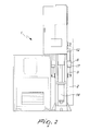
- the reference numeral 1 generally designates a compaction press.
- the press 1 comprises a supporting structure 2, which rests (and is optionally also fixed) on the floor; a movable arm 3 for supporting a management and control unit 4 is associated with the structure 2.
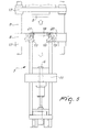
- the press 1 is provided with one or more pairs of plugs, an upper plug 5 and a lower plug 6, and a die supporting assembly 7 constituted by a cross-member 8, which can perform a translational motion along four guiding columns 9, which are fixed to the structure 1 and are distributed substantially along the external perimeter of the cross-member 8 proximate to the corners, by a containment rim supporting table 10, and by a footing 11.
- a plate 12 for accommodating the upper plug 5 is also guided along the columns 9.
- the cross-member 8 is provided with a frustum-shaped receptacle 13, whose shape and dimensions are complementary to the containment rim supporting table 10, said containment rim supporting table and said receptacle being mutually associable, in coaxial conditions imposed by the taper, by bolting when they are forced one inside to the other.
- the frustum-shaped receptacle 13 and the containment rim supporting table 10 have an angle comprised between two diametrically opposite generatrices that span substantially 30°.
- the cross-member 8 can perform a vertical translational motion by means of two hydraulic pistons 14, which are arranged in diametrically opposite positions with respect to the receptacle 13 and have an upper movable end that is rigidly coupled to the lower face of the cross-member 8 and a lower end that is rigidly coupled to the supporting structure 2.
- the pistons 14 are actuated simultaneously and are mutually controlled, in terms of position and speed, for the correct translational motion of the cross-member 8: any advancement of one with respect to the other would in fact entail the tilting of the cross-member, with consequent malfunction of the press 1 and misalignment between the containment rim 18 and the plugs 5 and 6.
- the cross-member 8 is constituted by a metallic element, which has a substantially rectangular cross-section with four external arms 15, which protrude substantially from the corners along the directions of the diagonals, each arm 15 having an end hole 16 which accommodates, even indirectly, a respective column 9; each end hole can in fact accommodate stably a bush 17, which can slide on the respective column 9.
- the plate 12 is shaped like the cross-member 9 and has respective arms with end holes with which the bushes are associated, said bushes being able to slide on the respective columns 9.
- the containment rim 18 is mounted on the containment rim supporting table 10 so that the upper end protrudes slightly from the upper face of the containment rim supporting table 10.
- the cross-member 8 supports a fixed lamina 20, which is mounted on top, and a removable lamina 21, which is fixed above the upper end of the containment rim 18 and protrudes from the rim supporting table 10: the fixed lamina 20 and the movable lamina 21 have the same thickness.
- a cup 22 for feeding the powders to the die receives the powders from a hopper 23 through a duct 24; the cup 22 can slide on the upper surface of the laminas 20 and 21, and in the inactive position rests exclusively on the fixed lamina 20 and can move by way of the action of a motor 25 from said inactive position to the position for releasing the powders that corresponds to its overlap on the upper opening of the containment rim 18.
- the cup 22 has scrapers, which ensure that in sliding on the surface of the laminas 20 and 21 it does not scatter metallic powders thereon; gliding of the cup 22 on the laminas 20 and 21 is ensured by the fact that the laminas have the same thickness and therefore there are no discontinuities in the transition from one to the other.
- the die supporting assembly with the new containment rim 18 mounted thereon, can then be arranged again below the cross-member 8, making the cross-member 8 descend until the seat 13 is forced onto the rim supporting table 10, so that their taper forces their mutual alignment. At this point, it is possible to fix the rim supporting table 10 by bolting to the cross-member 8.
- the cross-member 8 and the plate 12 are constantly guided on the fixed columns 9 and are therefore perfectly aligned, and by ensuring, by way of the conical coupling, a perfect alignment between the receptacle 13 and the rim supporting table 10, the containment rim 18 is perfectly aligned with the upper plug 5 and with the lower plug 6. This ensures that the pressing operations are performed with maximum efficiency, obtaining correctly formed products and avoiding the risk of damaging the mating parts due to incorrect alignments.
- the cup for feeding the powders 22 to the containment rim 18 continues to rest on the fixed lamina 20 in the inactive position: advantageously with respect to conventional presses, it is not necessary to disassemble the cup 22 as well, an operation which requires interrupting the duct 24 to prevent the outflow of the powders.
Landscapes
- Engineering & Computer Science (AREA)
- Mechanical Engineering (AREA)
- Manufacturing & Machinery (AREA)
- Press Drives And Press Lines (AREA)
- Powder Metallurgy (AREA)
- Presses And Accessory Devices Thereof (AREA)
Abstract
Description
Claims (13)
- A compacting press, of the type that comprises at least one pair of plugs, an upper one (5) and a lower one (6), a die supporting assembly (7), constituted by a cross-member (8) that can perform a translational motion along appropriately provided guides, fixed to the structure of the press (1), a containment rim supporting table (10) and a footing (11), and the corresponding movement means, characterized in that guiding columns (9) fixed to the structure (1) are distributed substantially along the external perimeter of the cross-member (8), said columns (9) guiding both said cross-member (8) and an upper plate (12) for accommodating the upper plug (5), and in that said cross-member (8) has a frustum-shaped receptacle (13), whose shape and dimensions are complementary to those of the containment rim supporting table (10), said table (10) and said receptacle (13) being mutually associable, in coaxiality conditions imposed by the taper, by way of removable coupling elements when they are forced one inside the other.
- The press according to claim 1, characterized in that said means for moving the cross-member (8) comprise two hydraulic pistons (14), in which the upper end is rigidly coupled to the lower face of the cross-member (8) and the lower end is rigidly coupled to the supporting structure (2), said pistons (14) being actuated simultaneously and mutually controlled, in terms of position and speed, for the correct translational motion of said cross-member (8).
- The press according to claim 1, characterized in that said guiding columns (9) are four, are fixed to the press (1), and are arranged approximate to the corners of said cross-member (8).
- The press according to claims 1 and 3, characterized in that said cross-member (8) is constituted by a metallic element that has a substantially rectangular cross-section with four external arms (15) that branch out from the corners along the directions of the diagonals, each arm (15) being provided with an end hole (16) in which a respective column (9) is accommodated even indirectly.
- The press according to claim 4, characterized in that each one of said end holes (16) accommodates a bush (17), which is rigidly coupled and is engaged on the column (9) so that it can slide.
- The press according to claims 1 and 3, characterized in that said upper plate (12) for accommodating the upper plug (5) has a substantially rectangular cross-section, with four external arms that protrude substantially from the corners along the directions of the diagonals, each arm being provided with an end hole which internally accommodates, even indirectly, a respective column (9).
- The press according to claim 6, characterized in that each one of said end holes accommodates a rigidly coupled bush, in which said column (9) can slide.
- The press according to one or more of the preceding claims, characterized in that said frustum-shaped receptacle (13) and said rim supporting table (10) have an angle of substantially 30° comprised between two diametrically opposite generatrices.
- The press according to one or more of the preceding claims, characterized in that said containment rim (18) is fitted on said rim supporting table (10) so that its upper end protrudes slightly from the upper face of said rim supporting table (10).
- The press according to claim 9, characterized in that said cross-member (8) rigidly supports, in an upper region, a fixed lamina (20) and a removable lamina (21), which is fixed above the upper end of the containment rim (18) and protrudes from rim supporting table (10), said fixed lamina (20) and said movable lamina (21) having the same thickness.
- The press according to claim 10, characterized in that a cup (22) for feeding the powders to the die can slide on the upper surface of said lamina (20, 21) and rests, in the inactive position, exclusively on said fixed lamina (20).
- A method for replacing a die supporting assembly in a press (1), according to one or more of the preceding claims, comprising the steps of: lifting said cross-member (8) with respect to the upper end of said lower plug (6) until it is spaced from said end by an extent that is greater than the height of the rim supporting table (10); freeing from the coupling elements said rim supporting table (10) from said cross-member (8), removing the entire die supporting assembly from the press (1); replacing said containment rim (18) in the rim supporting table (10); reinserting the die supporting assembly (11) in the press (1); arranging again the rim supporting table (10) below the cross-member (8); causing the descent of the cross-member (8) until the receptacle (13) is forced onto the rim supporting table (10), ensuring alignment by way of the conical mating; and fixing the rim supporting table (10) by means of said elements for coupling to the cross-member (8).
- The method according to claim 12, characterized in that during all the operations said cup for feeding the powders (22) to the die (15) remains in contact against said fixed lamina (20) in the inactive position.
Applications Claiming Priority (2)
| Application Number | Priority Date | Filing Date | Title |
|---|---|---|---|
| ITBO20040163 | 2004-03-19 | ||
| ITBO20040163 ITBO20040163A1 (en) | 2004-03-19 | 2004-03-19 | COMPACTING PRESS |
Publications (3)
| Publication Number | Publication Date |
|---|---|
| EP1586396A2 true EP1586396A2 (en) | 2005-10-19 |
| EP1586396A3 EP1586396A3 (en) | 2006-12-20 |
| EP1586396B1 EP1586396B1 (en) | 2012-10-31 |
Family
ID=34939008
Family Applications (1)
| Application Number | Title | Priority Date | Filing Date |
|---|---|---|---|
| EP20050102126 Expired - Lifetime EP1586396B1 (en) | 2004-03-19 | 2005-03-17 | Compacting Press |
Country Status (2)
| Country | Link |
|---|---|
| EP (1) | EP1586396B1 (en) |
| IT (1) | ITBO20040163A1 (en) |
Cited By (5)
| Publication number | Priority date | Publication date | Assignee | Title |
|---|---|---|---|---|
| WO2010015823A1 (en) * | 2008-08-06 | 2010-02-11 | Patheon Uk Limited | Rapid low-cost manufacture of tablets using disposable equipment |
| CN101961929A (en) * | 2010-06-18 | 2011-02-02 | 东莞市飞新达精密机械科技有限公司 | Precision hot press upper die landing gear |
| CN102294837A (en) * | 2011-08-04 | 2011-12-28 | 安徽中人科技有限责任公司 | Medicine pressing machine for preparing small-diameter granular implanting agent by powdery materials |
| CN101676096B (en) * | 2008-09-16 | 2012-11-21 | 许维群 | Full-automatic powder hydraulic forming machine and pressing technique thereof |
| CN106694875A (en) * | 2016-11-18 | 2017-05-24 | 扬州源智造科技有限公司 | Servo press applied to powder metallurgy pressing forming machining |
Families Citing this family (1)
| Publication number | Priority date | Publication date | Assignee | Title |
|---|---|---|---|---|
| CN106925780B (en) * | 2017-04-18 | 2020-06-09 | 扬州鼎隆机械有限公司 | Integrated mechanism of multilayer die carrier and press |
Family Cites Families (3)
| Publication number | Priority date | Publication date | Assignee | Title |
|---|---|---|---|---|
| US2800684A (en) * | 1953-07-28 | 1957-07-30 | Ncr Co | Apparatus for forming powdered metal parts |
| US2867844A (en) * | 1954-01-18 | 1959-01-13 | Baldwin Lima Hamilton Corp | Press for molding powdered material |
| ES2247096T3 (en) * | 2000-04-28 | 2006-03-01 | Morphic Technologies Aktiebolag | METHOD AND IMPACT MACHINE TO FORM A BODY. |
-
2004
- 2004-03-19 IT ITBO20040163 patent/ITBO20040163A1/en unknown
-
2005
- 2005-03-17 EP EP20050102126 patent/EP1586396B1/en not_active Expired - Lifetime
Cited By (6)
| Publication number | Priority date | Publication date | Assignee | Title |
|---|---|---|---|---|
| WO2010015823A1 (en) * | 2008-08-06 | 2010-02-11 | Patheon Uk Limited | Rapid low-cost manufacture of tablets using disposable equipment |
| CN101676096B (en) * | 2008-09-16 | 2012-11-21 | 许维群 | Full-automatic powder hydraulic forming machine and pressing technique thereof |
| CN101961929A (en) * | 2010-06-18 | 2011-02-02 | 东莞市飞新达精密机械科技有限公司 | Precision hot press upper die landing gear |
| CN101961929B (en) * | 2010-06-18 | 2012-07-25 | 东莞市飞新达精密机械科技有限公司 | Upper mould undercarriage of precision thermal press |
| CN102294837A (en) * | 2011-08-04 | 2011-12-28 | 安徽中人科技有限责任公司 | Medicine pressing machine for preparing small-diameter granular implanting agent by powdery materials |
| CN106694875A (en) * | 2016-11-18 | 2017-05-24 | 扬州源智造科技有限公司 | Servo press applied to powder metallurgy pressing forming machining |
Also Published As
| Publication number | Publication date |
|---|---|
| EP1586396B1 (en) | 2012-10-31 |
| ITBO20040163A1 (en) | 2004-06-19 |
| EP1586396A3 (en) | 2006-12-20 |
Similar Documents
| Publication | Publication Date | Title |
|---|---|---|
| EP2135695B1 (en) | Permanent mold casting machine and method for its use | |
| EP1586396B1 (en) | Compacting Press | |
| KR101593871B1 (en) | Mould rotating device | |
| US12134208B2 (en) | Device for producing concrete slabs | |
| KR102364963B1 (en) | Press for shaping pellets in a restricted and hostile environment and method for assembling the press | |
| JPH02274398A (en) | Press provided with tool mount | |
| EP0035568B1 (en) | Brick forming apparatus | |
| ES2399334T3 (en) | Press tooling | |
| EP1364765B1 (en) | Injection molding machine with compensation of bending moment on stationary platen | |
| CN214977023U (en) | A high-precision punching and shearing device for phosphor bronze rods | |
| KR102242102B1 (en) | A Device for Manufacturing Briquette | |
| EP0916461B1 (en) | Pressing device | |
| EP0753396B1 (en) | Device suitable to be used with a pressing apparatus | |
| KR100297192B1 (en) | Movable frame type press | |
| CN216801370U (en) | Connector die capable of achieving continuous stamping | |
| CN214290305U (en) | Stamping die for water gap of die casting | |
| CN210023531U (en) | Hardware mould automatic feeding equipment | |
| US4368020A (en) | Mold box wedging assembly | |
| KR102960127B1 (en) | Press mold with integral frame structure for precious metal processing | |
| EP1145812A1 (en) | Autonomous hydraulic mould for the formation of ceramic elements | |
| KR20170001787U (en) | Polygon prism-shaped bush for mold and the mold using the same | |
| JP2009018318A (en) | Powder forming apparatus | |
| SU1579624A1 (en) | Die for cold forging | |
| JPS6213724Y2 (en) | ||
| KR20220085873A (en) | Extraction apparatus of injection molding |
Legal Events
| Date | Code | Title | Description |
|---|---|---|---|
| PUAI | Public reference made under article 153(3) epc to a published international application that has entered the european phase |
Free format text: ORIGINAL CODE: 0009012 |
|
| AK | Designated contracting states |
Kind code of ref document: A2 Designated state(s): AT BE BG CH CY CZ DE DK EE ES FI FR GB GR HU IE IS IT LI LT LU MC NL PL PT RO SE SI SK TR |
|
| AX | Request for extension of the european patent |
Extension state: AL BA HR LV MK YU |
|
| PUAL | Search report despatched |
Free format text: ORIGINAL CODE: 0009013 |
|
| RIN1 | Information on inventor provided before grant (corrected) |
Inventor name: BELLUZZI, DANTE |
|
| AK | Designated contracting states |
Kind code of ref document: A3 Designated state(s): AT BE BG CH CY CZ DE DK EE ES FI FR GB GR HU IE IS IT LI LT LU MC NL PL PT RO SE SI SK TR |
|
| AX | Request for extension of the european patent |
Extension state: AL BA HR LV MK YU |
|
| RIC1 | Information provided on ipc code assigned before grant |
Ipc: B30B 15/02 20060101ALI20061110BHEP Ipc: B30B 15/30 20060101ALI20061110BHEP Ipc: B30B 15/04 20060101ALI20061110BHEP Ipc: B30B 11/02 20060101ALI20061110BHEP Ipc: B22F 3/03 20060101AFI20050713BHEP |
|
| 17P | Request for examination filed |
Effective date: 20070601 |
|
| AKX | Designation fees paid |
Designated state(s): AT BE BG CH CY CZ DE DK EE ES FI FR GB GR HU IE IS IT LI LT LU MC NL PL PT RO SE SI SK TR |
|
| 17Q | First examination report despatched |
Effective date: 20081118 |
|
| RAP1 | Party data changed (applicant data changed or rights of an application transferred) |
Owner name: SACMI COOPERATIVA MECCANICI IMOLA SOCIETA' COOPERA |
|
| GRAP | Despatch of communication of intention to grant a patent |
Free format text: ORIGINAL CODE: EPIDOSNIGR1 |
|
| GRAS | Grant fee paid |
Free format text: ORIGINAL CODE: EPIDOSNIGR3 |
|
| GRAA | (expected) grant |
Free format text: ORIGINAL CODE: 0009210 |
|
| AK | Designated contracting states |
Kind code of ref document: B1 Designated state(s): AT BE BG CH CY CZ DE DK EE ES FI FR GB GR HU IE IS IT LI LT LU MC NL PL PT RO SE SI SK TR |
|
| REG | Reference to a national code |
Ref country code: GB Ref legal event code: FG4D Ref country code: CH Ref legal event code: EP |
|
| REG | Reference to a national code |
Ref country code: AT Ref legal event code: REF Ref document number: 581704 Country of ref document: AT Kind code of ref document: T Effective date: 20121115 |
|
| REG | Reference to a national code |
Ref country code: IE Ref legal event code: FG4D |
|
| REG | Reference to a national code |
Ref country code: DE Ref legal event code: R096 Ref document number: 602005036762 Country of ref document: DE Effective date: 20121227 |
|
| REG | Reference to a national code |
Ref country code: LT Ref legal event code: MG4D |
|
| REG | Reference to a national code |
Ref country code: NL Ref legal event code: VDEP Effective date: 20121031 |
|
| PG25 | Lapsed in a contracting state [announced via postgrant information from national office to epo] |
Ref country code: IS Free format text: LAPSE BECAUSE OF FAILURE TO SUBMIT A TRANSLATION OF THE DESCRIPTION OR TO PAY THE FEE WITHIN THE PRESCRIBED TIME-LIMIT Effective date: 20130228 Ref country code: SE Free format text: LAPSE BECAUSE OF FAILURE TO SUBMIT A TRANSLATION OF THE DESCRIPTION OR TO PAY THE FEE WITHIN THE PRESCRIBED TIME-LIMIT Effective date: 20121031 Ref country code: FI Free format text: LAPSE BECAUSE OF FAILURE TO SUBMIT A TRANSLATION OF THE DESCRIPTION OR TO PAY THE FEE WITHIN THE PRESCRIBED TIME-LIMIT Effective date: 20121031 Ref country code: NL Free format text: LAPSE BECAUSE OF FAILURE TO SUBMIT A TRANSLATION OF THE DESCRIPTION OR TO PAY THE FEE WITHIN THE PRESCRIBED TIME-LIMIT Effective date: 20121031 Ref country code: ES Free format text: LAPSE BECAUSE OF FAILURE TO SUBMIT A TRANSLATION OF THE DESCRIPTION OR TO PAY THE FEE WITHIN THE PRESCRIBED TIME-LIMIT Effective date: 20130211 Ref country code: LT Free format text: LAPSE BECAUSE OF FAILURE TO SUBMIT A TRANSLATION OF THE DESCRIPTION OR TO PAY THE FEE WITHIN THE PRESCRIBED TIME-LIMIT Effective date: 20121031 |
|
| PG25 | Lapsed in a contracting state [announced via postgrant information from national office to epo] |
Ref country code: SI Free format text: LAPSE BECAUSE OF FAILURE TO SUBMIT A TRANSLATION OF THE DESCRIPTION OR TO PAY THE FEE WITHIN THE PRESCRIBED TIME-LIMIT Effective date: 20121031 Ref country code: BE Free format text: LAPSE BECAUSE OF FAILURE TO SUBMIT A TRANSLATION OF THE DESCRIPTION OR TO PAY THE FEE WITHIN THE PRESCRIBED TIME-LIMIT Effective date: 20121031 Ref country code: CY Free format text: LAPSE BECAUSE OF FAILURE TO SUBMIT A TRANSLATION OF THE DESCRIPTION OR TO PAY THE FEE WITHIN THE PRESCRIBED TIME-LIMIT Effective date: 20121031 Ref country code: PL Free format text: LAPSE BECAUSE OF FAILURE TO SUBMIT A TRANSLATION OF THE DESCRIPTION OR TO PAY THE FEE WITHIN THE PRESCRIBED TIME-LIMIT Effective date: 20121031 Ref country code: PT Free format text: LAPSE BECAUSE OF FAILURE TO SUBMIT A TRANSLATION OF THE DESCRIPTION OR TO PAY THE FEE WITHIN THE PRESCRIBED TIME-LIMIT Effective date: 20130228 Ref country code: GR Free format text: LAPSE BECAUSE OF FAILURE TO SUBMIT A TRANSLATION OF THE DESCRIPTION OR TO PAY THE FEE WITHIN THE PRESCRIBED TIME-LIMIT Effective date: 20130201 |
|
| PG25 | Lapsed in a contracting state [announced via postgrant information from national office to epo] |
Ref country code: CZ Free format text: LAPSE BECAUSE OF FAILURE TO SUBMIT A TRANSLATION OF THE DESCRIPTION OR TO PAY THE FEE WITHIN THE PRESCRIBED TIME-LIMIT Effective date: 20121031 Ref country code: SK Free format text: LAPSE BECAUSE OF FAILURE TO SUBMIT A TRANSLATION OF THE DESCRIPTION OR TO PAY THE FEE WITHIN THE PRESCRIBED TIME-LIMIT Effective date: 20121031 Ref country code: BG Free format text: LAPSE BECAUSE OF FAILURE TO SUBMIT A TRANSLATION OF THE DESCRIPTION OR TO PAY THE FEE WITHIN THE PRESCRIBED TIME-LIMIT Effective date: 20130131 Ref country code: DK Free format text: LAPSE BECAUSE OF FAILURE TO SUBMIT A TRANSLATION OF THE DESCRIPTION OR TO PAY THE FEE WITHIN THE PRESCRIBED TIME-LIMIT Effective date: 20121031 Ref country code: EE Free format text: LAPSE BECAUSE OF FAILURE TO SUBMIT A TRANSLATION OF THE DESCRIPTION OR TO PAY THE FEE WITHIN THE PRESCRIBED TIME-LIMIT Effective date: 20121031 |
|
| PG25 | Lapsed in a contracting state [announced via postgrant information from national office to epo] |
Ref country code: RO Free format text: LAPSE BECAUSE OF FAILURE TO SUBMIT A TRANSLATION OF THE DESCRIPTION OR TO PAY THE FEE WITHIN THE PRESCRIBED TIME-LIMIT Effective date: 20121031 |
|
| PLBE | No opposition filed within time limit |
Free format text: ORIGINAL CODE: 0009261 |
|
| STAA | Information on the status of an ep patent application or granted ep patent |
Free format text: STATUS: NO OPPOSITION FILED WITHIN TIME LIMIT |
|
| 26N | No opposition filed |
Effective date: 20130801 |
|
| PG25 | Lapsed in a contracting state [announced via postgrant information from national office to epo] |
Ref country code: MC Free format text: LAPSE BECAUSE OF NON-PAYMENT OF DUE FEES Effective date: 20130331 |
|
| REG | Reference to a national code |
Ref country code: CH Ref legal event code: PL |
|
| GBPC | Gb: european patent ceased through non-payment of renewal fee |
Effective date: 20130317 |
|
| REG | Reference to a national code |
Ref country code: DE Ref legal event code: R097 Ref document number: 602005036762 Country of ref document: DE Effective date: 20130801 |
|
| REG | Reference to a national code |
Ref country code: FR Ref legal event code: ST Effective date: 20131129 |
|
| REG | Reference to a national code |
Ref country code: IE Ref legal event code: MM4A |
|
| PG25 | Lapsed in a contracting state [announced via postgrant information from national office to epo] |
Ref country code: LI Free format text: LAPSE BECAUSE OF NON-PAYMENT OF DUE FEES Effective date: 20130331 Ref country code: FR Free format text: LAPSE BECAUSE OF NON-PAYMENT OF DUE FEES Effective date: 20130402 Ref country code: CH Free format text: LAPSE BECAUSE OF NON-PAYMENT OF DUE FEES Effective date: 20130331 Ref country code: GB Free format text: LAPSE BECAUSE OF NON-PAYMENT OF DUE FEES Effective date: 20130317 Ref country code: IE Free format text: LAPSE BECAUSE OF NON-PAYMENT OF DUE FEES Effective date: 20130317 |
|
| PG25 | Lapsed in a contracting state [announced via postgrant information from national office to epo] |
Ref country code: TR Free format text: LAPSE BECAUSE OF FAILURE TO SUBMIT A TRANSLATION OF THE DESCRIPTION OR TO PAY THE FEE WITHIN THE PRESCRIBED TIME-LIMIT Effective date: 20121031 |
|
| PG25 | Lapsed in a contracting state [announced via postgrant information from national office to epo] |
Ref country code: LU Free format text: LAPSE BECAUSE OF NON-PAYMENT OF DUE FEES Effective date: 20130317 Ref country code: HU Free format text: LAPSE BECAUSE OF FAILURE TO SUBMIT A TRANSLATION OF THE DESCRIPTION OR TO PAY THE FEE WITHIN THE PRESCRIBED TIME-LIMIT; INVALID AB INITIO Effective date: 20050317 |
|
| PGFP | Annual fee paid to national office [announced via postgrant information from national office to epo] |
Ref country code: IT Payment date: 20190219 Year of fee payment: 15 Ref country code: DE Payment date: 20190219 Year of fee payment: 15 |
|
| PGFP | Annual fee paid to national office [announced via postgrant information from national office to epo] |
Ref country code: AT Payment date: 20190221 Year of fee payment: 15 |
|
| REG | Reference to a national code |
Ref country code: DE Ref legal event code: R119 Ref document number: 602005036762 Country of ref document: DE |
|
| REG | Reference to a national code |
Ref country code: AT Ref legal event code: MM01 Ref document number: 581704 Country of ref document: AT Kind code of ref document: T Effective date: 20200317 |
|
| PG25 | Lapsed in a contracting state [announced via postgrant information from national office to epo] |
Ref country code: AT Free format text: LAPSE BECAUSE OF NON-PAYMENT OF DUE FEES Effective date: 20200317 Ref country code: DE Free format text: LAPSE BECAUSE OF NON-PAYMENT OF DUE FEES Effective date: 20201001 |
|
| PG25 | Lapsed in a contracting state [announced via postgrant information from national office to epo] |
Ref country code: IT Free format text: LAPSE BECAUSE OF NON-PAYMENT OF DUE FEES Effective date: 20200317 |