EP1586389B1 - Dispositif de production d'un tube metallique a section ovale et procede de production associe - Google Patents
Dispositif de production d'un tube metallique a section ovale et procede de production associe Download PDFInfo
- Publication number
- EP1586389B1 EP1586389B1 EP03771321A EP03771321A EP1586389B1 EP 1586389 B1 EP1586389 B1 EP 1586389B1 EP 03771321 A EP03771321 A EP 03771321A EP 03771321 A EP03771321 A EP 03771321A EP 1586389 B1 EP1586389 B1 EP 1586389B1
- Authority
- EP
- European Patent Office
- Prior art keywords
- punch
- metal tube
- section
- oval cross
- taper
- Prior art date
- Legal status (The legal status is an assumption and is not a legal conclusion. Google has not performed a legal analysis and makes no representation as to the accuracy of the status listed.)
- Expired - Lifetime
Links
Images






Classifications
-
- B—PERFORMING OPERATIONS; TRANSPORTING
- B21—MECHANICAL METAL-WORKING WITHOUT ESSENTIALLY REMOVING MATERIAL; PUNCHING METAL
- B21C—MANUFACTURE OF METAL SHEETS, WIRE, RODS, TUBES, PROFILES OR LIKE SEMI-MANUFACTURED PRODUCTS OTHERWISE THAN BY ROLLING; AUXILIARY OPERATIONS USED IN CONNECTION WITH METAL-WORKING WITHOUT ESSENTIALLY REMOVING MATERIAL
- B21C23/00—Extruding metal; Impact extrusion
- B21C23/21—Presses specially adapted for extruding metal
- B21C23/217—Tube extrusion presses
-
- B—PERFORMING OPERATIONS; TRANSPORTING
- B21—MECHANICAL METAL-WORKING WITHOUT ESSENTIALLY REMOVING MATERIAL; PUNCHING METAL
- B21C—MANUFACTURE OF METAL SHEETS, WIRE, RODS, TUBES, PROFILES OR LIKE SEMI-MANUFACTURED PRODUCTS OTHERWISE THAN BY ROLLING; AUXILIARY OPERATIONS USED IN CONNECTION WITH METAL-WORKING WITHOUT ESSENTIALLY REMOVING MATERIAL
- B21C23/00—Extruding metal; Impact extrusion
- B21C23/02—Making uncoated products
- B21C23/18—Making uncoated products by impact extrusion
- B21C23/186—Making uncoated products by impact extrusion by backward extrusion
-
- B—PERFORMING OPERATIONS; TRANSPORTING
- B21—MECHANICAL METAL-WORKING WITHOUT ESSENTIALLY REMOVING MATERIAL; PUNCHING METAL
- B21C—MANUFACTURE OF METAL SHEETS, WIRE, RODS, TUBES, PROFILES OR LIKE SEMI-MANUFACTURED PRODUCTS OTHERWISE THAN BY ROLLING; AUXILIARY OPERATIONS USED IN CONNECTION WITH METAL-WORKING WITHOUT ESSENTIALLY REMOVING MATERIAL
- B21C25/00—Profiling tools for metal extruding
- B21C25/02—Dies
Definitions
- the present invention relates to a production apparatus and method for a metal tube having an oval cross section.
- a conventional aluminum tube having an integral outlet mouth is produced by an impact extruding method (impact press).
- impact press a disk-shaped aluminum slug punched out of a rolled aluminum plate (having a purity of 99.7% or higher) is used as a material.
- the slug is put in a die, and pressed by moving a punch toward the die thereby to be instantaneously extruded through a gap defined between the punch and the die owing to its ductility.
- the tube is formed.
- the aluminum tube has the following advantages:
- the die and the tube to be formed should each have a circular cross section. This is because the aluminum slug as the material is circular as seen from a front side thereof and is required to be uniformly extruded through the gap defined between the punch and the die circumferentially of the punch for improvement of yield and for reduction of a material loss. Further, it has also been considered impossible to properly handle a metal tube having a noncircular cross section after the press.
- a similar production apparatus for extruding a non-circular hollow tube is disclosed in US 2,533,942 .
- This extruding apparatus comprises a punch of non-circular cross sections, which is long and of relatively small cross sectional area, cooperating with a suitably shaped die cavity. Additionally, the punch is provided at its lower end working surface with two sets of sloped faces of predetermined relative angularity and areas to cause an adequate flow of the extruded metal towards the narrow and container walls, as well as towards the longer side walls, during the extruding operation. This way, the metal is distributed where it is needed to produce a desired wall thickness throughout the entire container.
- the particular arrangement of the sloped faces depends on the cross section of the hollow tube to be extruded. Also this apparatus does not achieve the reduce the hem portion at the end of the oval body which reduces the efficiency of the extruding apparatus.
- a plastic tube such as disclosed in Japanese Unexamined Utility Model No. 64-51040 (1989 ) is used.
- the present invention provides a production apparatus according to claim 1 and a production method according to claim 9.
- a production apparatus for a metal tube having an oval cross section includes: an impact extrusion device which impact-extrudes a disk-shaped metal slug to form a metal tube integrally including a mouth, a shoulder and a body of an oval cross section; and a trimming device which trims off a hem portion of the oval body of the tube formed by the impact extrusion device by a turning operation.
- the metal tube include aluminum tubes, lead tubes, tin tubes and alloy tubes.
- the metal tube according to the present invention is used in a variety of applications for tooth pastes, medicines, cosmetics, domestic products, food products and the like.
- the metal slug typically has a circular shape, but may have an oval shape.
- the impact extrusion device includes a columnar punch having an axis, a press die, and a stripper provided around the punch in an axially movable manner.
- the punch includes a punch shaft, a punch head provided at a distal end of the shaft and including a punch shoulder.
- the die includes a die base, and a die ring which retains the metal slug therein.
- the die base and the die ring may be a unitary member or separate members combined together.
- the punch shoulder has an outer surface having an oval cross section, and the die ring has an inner peripheral surface having an oval cross section.
- the punch shoulder is insertable in the die ring.
- a gap is defined between the die ring and the punch shoulder inserted in the die ring circumferentially of the punch shoulder. The metal material is extruded through the gap, whereby the metal tube is allowed to have an oval body.
- the punch head includes a base of an oval cross section connected to the punch shaft, the punch shoulder which is provided at a distal end of the base and has a greater diameter than the base, and a first taper surface having an oval cross section which has a diameter progressively decreasing toward a distal end thereof from the punch shoulder.
- the punch head further includes a punch nose which extends from the distal end of the first taper surface to a distal end of the punch head.
- the punch shoulder defines an interior surface of the body of the metal tube, and the first taper surface defines an interior surface of the shoulder of the metal tube.
- the punch nose defines an interior surface of the mouth of the metal tube.
- a typical phenomenon liable to occur in a conventional impact extruding process will be described.
- a circular aluminum slug is formed with the use of a circular die by the impact press
- a part of the slug corresponding to the hem portion of the metal tube is first extruded.
- the hem portion of the tube is undulated due to offset of the axes of the die and the punch and a difference in circularity between the die and the punch.
- This phenomenon inevitably occurs in the impact press for the formation of the conventional circular tube, and is expected to be exacerbated in the case of the oval tube.
- portions of the aluminum slug present on diametrically opposite sides of the minor axis of the punch are instantaneously extruded, but portions of the aluminum slug present on diametrically opposite sides of the major axis of the punch are extruded with a time lag because of greater distances from the punch shoulder. Therefore, hem portions of the tube on the diametrically opposite sides of the major axis are significantly indented, so that a material loss is significantly increased.
- generating lines of the first taper surface on the diametrically opposite sides of the minor axis of the first taper surface preferably each form an angle of not smaller than 43 degrees and not greater than 53 degrees, more preferably not smaller than 46 degrees and not greater than 50 degrees, further more preferably about 48 degrees, with respect to the axis of the punch.
- the outer surface of the shoulder and the inner peripheral surface of the die ring are each preferably dimensioned so that the dimensional ratio of the minor axis to the major axis thereof is not smaller than 0.5 and not greater than 0.9, more preferably not smaller than 0.6 and not greater than 0.8.
- the punch shaft may be columnar with an oval cross section or a circular cross section like the base of the punch head.
- the punch shaft has a circular cross section and the punch head is detachable from the punch shaft, the formation of a metal tube of a circular cross section can be achieved easily and speedily by replacing the punch head and the die with a circular punch head and a circular die, respectively.
- the punch shaft has a circular cylindrical shape
- the length of the minor axis of the base of the punch head is equal to the diameter of the punch shaft
- the punch head has second taper surfaces respectively defined on proximal peripheral portions thereof on diametrically opposite sides of the major axis thereof and connected to an outer peripheral surface of the punch shaft.
- Generating lines of the second taper surfaces on the diametrically opposite sides of the major axis of the punch head each form an angle of not smaller than 10 degrees and not greater than 60 degrees, more preferably 15 degrees to 30 degrees, with respect to the axis of the punch.
- the portions of the oval head on the diametrically opposite sides of the major axis are connected to the circular cylindrical shaft by the second taper surfaces, whereby steps can be eliminated which may otherwise be formed on a junction between the head and the shaft to catch the metal tube when the metal tube is released from the punch. This ensures smooth releasing of the metal tube.
- the stripper includes a plurality of segments circumferentially arranged.
- the segments are each radially movable.
- Distal edges of inner peripheral surfaces of the segments may each have an arcuate shape which conforms to the outer peripheral shape of the base of the punch head.
- a distal edge of an inner peripheral surface of the stripper (the combined inner peripheral surfaces of the respective segments) has an oval shape which conforms to the outer peripheral shape of the base of the punch head.
- the punch shaft has a circular cylindrical shape, gaps are formed between ones of the segments located on the diametrically opposite sides of the major axis of the stripper and the punch shaft.
- the metal tube can be assuredly removed from the punch by the stripper, because the inner peripheral edge of the stripper is configured so as to conform to the base of the punch head having a slightly smaller diameter than the punch shoulder which defines the interior surface of the tube. Even if the stripper is rotated, the formation of the circular tube is not adversely affected by the rotation of the stripper. In the formation of the inventive oval tube, however, it is necessary to prevent the rotation of the stripper. Therefore, a positioning portion such as a key groove is preferably provided at a predetermined position of a peripheral surface of the stripper. Thus, the stripper is fixed with respect to the direction of the rotation by engaging the positioning portion with a stripper holder.
- a biasing member may be provided for biasing the respective segments radially inward. This prevents the respective segments from being subjected to an excess load.
- the trimming device includes a mandrel around which the metal tube formed by the impact extrusion device is fitted, the mandrel being rotatable about an axis thereof, and a cutting tool which cuts the hem portion of the metal tube fitted around the mandrel.
- the mandrel includes a taper portion having a truncated conical shape which has a diameter progressively decreasing toward a distal end thereof.
- a proximal portion of the taper portion has a diameter greater than the length of the major axis of an inner peripheral surface of the body of the metal tube.
- the hem portion of the metal tube is cut at an axially middle position of the taper portion by the cutting tool.
- the hem portion of the metal tube fitted around the mandrel is flared into a circular shape by the taper portion.
- the metal tube having the flared hem portion is rotated relative to the cutting tool by the rotation of the mandrel, whereby the hem portion of the tube is circumferentially cut by the cutting tool.
- the hem portion of the tube having an oval cross section is once deformed into a circular shape, and then cut. Therefore, the cutting operation can be easily performed.
- the metal tube experiences work hardening during the impact press. Therefore, the metal tube is easily restored into the original oval shape even after being deformed.
- the taper portion of the mandrel has a groove provided in an outer peripheral surface thereof in association with the cutting tool as extending circumferentially thereof.
- the hem portion can be assuredly cut by permitting the cutting tool to intrude into the groove with an interior surface of the hem portion of the tube being deformed to be fitted around the mandrel.
- the inventive production apparatus further includes an annealing device which anneals the metal tube formed and hardened by the impact extrusion performed by the impact extrusion device, and a restoration device which restores the hem portion of the tube deformed into the circular shape by the mandrel of the trimming device into the oval shape.
- the restoration device may be provided in the annealing device or in the impact extrusion device, or provided between the impact extrusion device and the annealing device.
- the metal tube with its hem portion restored into the oval shape by the restoration device is annealed by the annealing device.
- the metal of the tube having the oval body is softened, and a lubricant applied to the slug for the impact extrusion is evaporated by heat.
- a production method for a metal tube having an oval cross section includes the steps of: impact-extruding a disk-shaped metal slug to form a metal tube integrally including a mouth, a shoulder and a body of an oval cross section; and trimming a hem portion of the oval body and the mouth of the tube formed in the impact extrusion step by a turning operation.
- the impact extrusion step is performed by an impact extrusion device including a columnar punch having an axis, a press die and a stripper provided around the punch in an axially movable manner.
- the punch includes a punch shaft, and a punch head provided at a distal end of the shaft and including a punch shoulder.
- the die includes a die base, and a die ring which retains the metal slug therein.
- the punch shoulder has an outer surface having an oval cross section, and the die ring has an inner peripheral surface having an oval cross section. The punch shoulder is insertable in the die ring.
- the punch head includes a base of an oval cross section connected to the punch shaft, the punch shoulder which is provided at a distal end of the base and has a greater diameter than the base, and a first taper surface having an oval cross section which has a diameter progressively decreasing toward a distal end thereof from the punch shoulder.
- Generating lines of the first taper surface on diametrically opposite sides of the major axis of the first taper surface preferably each form an angle of not smaller than 55 degrees and not greater than 65 degrees with respect to the axis of the punch.
- generating lines of the first taper surface on diametrically opposite sides of the minor axis of the first taper surface preferably each form an angle of not smaller than 43 degrees and not greater than 53 degrees with respect to the axis of the punch.
- the outer surface of the shoulder and the inner peripheral surface of the die ring are each preferably dimensioned so that the ratio of the minor axis to the major axis thereof is not smaller than 0.6 and not greater than 0.9.
- the punch shaft has a circular cylindrical shape.
- the length of the minor axis of the base of the punch head is equal to the diameter of the punch shaft, and the punch head has second taper surfaces respectively defined on proximal peripheral portions thereof on diametrically opposite sides of the major axis thereof and connected to an outer peripheral surface of the punch shaft. Generating lines of the second taper surfaces on the diametrically opposite sides of the major axis of the punch head each form an angle of not smaller than 10 degrees and not greater than 60 degrees with respect to the axis of the punch.
- the stripper includes a plurality of segments circumferentially arranged.
- the segments are each radially movable. Distal edges of inner peripheral surfaces of the segments may each have an arcuate shape which conforms to the outer peripheral shape of the base of the punch head.
- a proximal portion of the metal tube formed to be fitted around the punch by the impact extrusion is pushed toward a distal end of the punch by the stripper, whereby the metal tube is released from the punch.
- the segments may be moved radially outward or inward to conform to the outer peripheral shape of the punch during the releasing.
- the hem portion of the metal tube which is formed and hardened in the impact extrusion step is deformed into a circular shape and, after the hem portion is restored into an oval shape, the metal tube is annealed to be softened.
- the trimming step is performed by a trimming device including a mandrel around which the metal tube formed by the impact extrusion device is fitted, the mandrel being rotatable about an axis thereof, and a cutting tool which cuts the body of the metal tube fitted around the mandrel at a predetermined axial position.
- the mandrel includes a taper portion having a truncated conical shape which has a diameter progressively decreasing toward a distal end thereof.
- a proximal portion of the taper portion has a diameter greater than the length of the major axis of an inner peripheral surface of the body of the metal tube.
- the hem portion of the metal tube is cut at an axially middle portion of the taper portion by the cutting tool.
- the hem portion of the metal tube fitted around the mandrel is flared into a circular shape by the taper portion.
- the metal tube having the flared hem portion is rotated relative to the cutting tool by the rotation of the mandrel, whereby the hem portion of the tube is circumferentially cut by the cutting tool.
- the taper portion of the mandrel has a groove provided in an outer peripheral surface thereof in association with the cutting tool as extending circumferentially thereof.
- the cutting tool is permitted to intrude into the groove during the cutting.
- the inventive production method further includes the steps of annealing the metal tube which is formed and hardened by the impact extrusion performed by the impact extrusion device, and restoring the hem portion of the tube deformed into the circular shape by the mandrel of the trimming device into the oval shape.
- the annealing step may follow the restoring step.
- the production method has substantially the same features as the inventive production apparatus.
- a metal tube having an oval cross section includes a mouth having a circular cross section, a body having an oval cross section, and a tapered shoulder formed integrally with the mouth and the body and connecting the mouth and the body.
- the inventive production apparatus and the inventive production method make it possible for the first time to produce the metal tube having such a novel shape.
- the inventive metal tube has advantages as a metal tube and, at the same time, has an increased volume because of the oval cross section of the body thereof. Further, the metal tube with a painted outer surface has an excellent appearance comparable to that of a plastic tube. Since the mouth has a circular cross section, the metal tube has a capping property, an air-tightness in a capped state and a mouth rigidity comparable to those of the existing metal tube.
- the body and the shoulder each have an oval shape, so that the shoulder can be easily collapsed along the minor axis thereof.
- a metal tube including a mouth, a shoulder and a body integrally formed has a disadvantage such that contents are likely to partly remain in the shoulder of the metal tube, the present invention eliminates this disadvantage. Since the metal tube has an oval shape, a multiplicity of such tubes can be efficiently stored by arranging the tubes in a proper direction.
- generating lines of the shoulder on diametrically opposite sides of the major axis of the shoulder preferably each form an angle of not smaller than 55 degrees and not greater than 65 degrees, more preferably not smaller than 58 degrees and not greater than 62 degrees, further more preferably about 60 degrees, with respect to an axis of the metal tube.
- generating lines of the shoulder on diametrically opposite sides of the minor axis of the shoulder preferably each form an angle of not smaller than 43 degrees and not greater than 53 degrees, more preferably not smaller than 46 degrees and not greater than 53 degrees, further more preferably about 48 degrees, with respect to the axis of the metal tube.
- the dimensional ratio of the minor axis to the major axis of the body is preferably not smaller than 0.5 and not greater than 0.9, more preferably not smaller than 0.6 and not greater than 0.8.
- Portions of the body on diametrically opposite sides of the minor axis of the body each have a greater wall thickness than portions of the body on diametrically opposite sides of the major axis of the body.
- the tube can be easily collapsed along the minor axis.
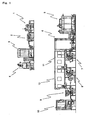
- Fig. 1 schematically illustrates the overall construction of an aluminum tube production apparatus (production line) as a production apparatus according to one embodiment of the present invention.
- the production apparatus includes an impact extrusion device 1, a trimming device 2, an annealing device 3, an interior coating device 4, a drying oven 5, an accumulator 6, a prime coating printer 7, an offset printer 8, a capping device 9, and a sealant applying device 10 disposed in this order from an upstream side of the line.
- the impact extrusion device 1 extrudes an aluminum slug by impact press to form a metal tube integrally including a mouth, a shoulder and a body having an oval cross section.
- the trimming device 2 trims unnecessary portions of the mouth and the hem portion of the tube formed by the impact press by a turning operation, and forms a thread on an outer circumferential surface of the mouth by a rolling operation.
- the annealing device 3 reheats the tube hardened in the impact press and then gradually cools the tube after the trimming of the mouth and the hem portion, whereby the tube is softened and a lubricant applied to the slug is evaporated.
- the interior coating device 4 sprays a predetermined paint on an interior surface of the annealed tube by a spray gun.
- the drying oven 5 heats the tube to evaporate a solvent of the paint sprayed on the interior surface to harden the paint.
- the accumulator 6 stores the tube until the paint on the interior surface of the tube is dried.
- the prime coating printer 7 applies a base coating agent on the body of the tube by a rubber roll.
- the base coating agent applied by the prime coating printer 7 is dried in a dryer 11. However, the base coating agent is not completely dried at this time point.
- the offset printer 8 performs an offset printing operation on the base coating agent with a plurality of colors (e.g., six colors).
- the print and the base coating agent are completely dried in a dryer 12.
- the capping device 9 caps the mouth of the tube by applying a predetermined torque.
- the sealant applying device 10 applies latex to a predetermined portion of the hem portion of the tube, and allows a solvent (depending on the type of the latex) to evaporate.
- the basic construction of each of the devices is conventionally known and, therefore, will not be described in detail. Notable modifications for the production of the oval tube will be explained below.
- the impact extrusion device 1 includes a cylindrical punch 13 having an axis, a press die 14, and a stripper 15 fitted around the punch 13 and movable axially of the punch 13.
- the punch 13 is moved toward and away from the die 14 by a lateral toggle crank press mechanism as shown in Fig. 2 .
- the driving mechanism for the punch 13 is not limited to the press mechanism, but any other mechanism such as a link mechanism may be used.
- the die 14 and the stripper 15 are respectively fixed to bases.
- the die 14 for the impact press has a recess, and essentially includes a die base and a die ring.
- the die base and the die ring are generally provided separately, but may be unitarily provided as respectively indicated by reference numerals 16, 17 in Figs. 3 to 5 .
- the die base 16 has a taper surface 18 which defines an outer peripheral surface of the shoulder of the aluminum tube, and a mouth defining surface 19 which defines an outer surface of the mouth of the aluminum tube.
- An inner peripheral surface 20 of the die ring 17 has an oval cross section.
- the taper surface 18 connects the oval inner peripheral surface 20 of the die ring and the circular mouth defining surface 19. Therefore, the taper surface 18 also has an oval cross section.
- generating lines of the taper surface 18 on diametrically opposite sides of the major axis of the taper surface each form an angle ⁇ 1 of about 60 degrees with respect to the axis
- generating lines on diametrically opposite sides of the minor axis each form an angle ⁇ 2 of about 47 degrees.
- the dimensional ratio of the minor axis b to the major axis a of the inner peripheral surface 20 of the die ring is about 0.76.
- an aluminum slug 21 deburred and coated with a lubricant is placed in the die ring 17.
- the aluminum slug 21 may be prepared by punch-pressing an aluminum material continuously cast from an aluminum blast furnace and rolled at two stages by a rolling mill, and annealing the punch-pressed material, or by cutting upper and lower surfaces of an ingot to remove oxide films, rolling the resulting ingot to adjust the thickness of the material, punching the material by a punch press, and annealing the punched material.
- Conventionally known circular slugs as shown in Fig. 6 are usable.
- the slug 21 preferably has an outer diameter which is slightly smaller than the length of the minor axis of the inner peripheral surface 20 of the die ring.
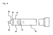
- the punch 13 essentially includes a circular cylindrical punch shaft 22, and a punch head 23 attached to a distal end of the punch shaft 22 by a joint bolt.
- the punch head 23 may be formed integrally with the shaft 22.
- the punch head 23 is preferably provided separately from the shaft 22 and detachable from the shaft 22 for replacement, because the punch head is subjected to great friction with aluminum thereby to be remarkably worn during the impact press.
- the punch head 23 includes a base 24 of an oval cross section connected to the punch shaft 22, a punch shoulder 25 provided at a distal end of the base 24 and having an oval cross section which has a greater diameter than the base 24, a first taper surface 26 having an oval cross section which has a diameter progressively decreasing toward a distal end thereof from the punch shoulder 25, and a punch nose 39 extending from a distal end of the taper surface 26 to a distal end of the punch head.
- the diameter of the punch shaft 23 is equal to the length of the minor axis of the base 24 of the punch head 23.
- the punch shoulder 25 has a cross section conformable to that of the inner peripheral surface 20 of the die ring.
- the tube can be formed as having a small body wall thickness on the order of 0.11 mm to 0.13 mm even if having an oval shape.
- the die ring 17 and the punch head 23 each have an oval shape. Therefore, it is necessary to confirm that the punch head 23 is accurately positioned with respect to the die ring 17 and correct a positional offset and an angular offset, if any, when the punch head 23 is inserted to a several millimeters into the die ring 17 after replacement of the punch head 23 or before start up of the line.
- the first taper surface 26 of the punch head 23 defines an interior surface of the shoulder of the tube, and conforms to the shape of the taper surface 18 of the die base 16. Generating lines of the first taper surface 26 on diametrically opposite sides of the major axis of the first taper surface each preferably form an angle of about 60 degrees with respect to the axis of the punch, and generating lines on diametrically opposite sides of the minor axis of the first taper surface 26 each preferably form an angle of about 49 degrees with respect to the axis of the punch.
- the inclination angles of the first taper surface 26 may be equal to the inclination angles of the shoulder defining taper surface 18 of the die base 16 throughout the circumference of the punch head.
- the inclination angles of the first taper surface 26 with respect to the axis may be smaller by about 1 degree to about 2 degrees than the inclination angles of the taper surface 18.
- the first taper surface 18 may have a step formed in a middle portion thereof, so that the inner surface of the shoulder is indented.
- the outer surface of the shoulder is curved as having a great curvature radius.
- the punch head 23 has second taper surfaces 27 provided on proximal peripheral portions thereof on diametrically opposite sides of the major axis thereof and connected to the outer peripheral surface of the punch shaft 23.
- the taper surfaces 27 are helpful to smoothly release the product from the punch 13 by the stripper 15.
- Generating lines of the taper surfaces 27 on diametrically opposite sides of the major axis of the punch head preferably each form an angle of 10 degrees to 60 degrees with respect to the axis of the punch.
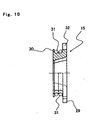
- Figs. 9 and 10 illustrate an example of the stripper 15.
- the stripper 15 has a ring shape as a whole, and has a through-hole provided at the center thereof and having an oval shape which conforms to the outer peripheral shape of the base 24 of the punch head 23. More specifically, the stripper 15 includes six fan-shaped segments 28 circumferentially arranged, and a combination of the six segments 28 defines the ring shape.
- the segments 28 each have two flanges 29, 30 provided in axially spaced relation.
- a ring-shaped biasing member 31 such as a coil spring is fitted between the flanges 29 and 30. The biasing member 31 is fitted over all the segments 28 to bias the segments 28 radially inward.
- the segments 28 are movable radially outward against a biasing force of the biasing member 31. Distal edges of inner peripheral surfaces of the segments 28 each have an arcuate shape which conforms to the shape of the outer periphery of the base 24 of the punch head 23 or the shape of the outer periphery of the punch shoulder 25.
- the stripper 15 preferably further includes rotation preventing portions 32 such as key grooves provided at predetermined circumferential positions thereof for preventing rotation of the stripper 15 about the axis.
- a stripper holder (not shown) which fixes the stripper 15 to a base is engaged with the rotation preventing portion 32.
- Figs. 11 and 12 illustrate another example 15' of the stripper.
- the stripper 15' essentially includes two segments 28' disposed in diametrically opposed relation.
- the segments 28' are respectively radially movable by driving air cylinders 33.
- the air cylinders 33 are each attached to rails 34 so as to be axially slidable, and supported by a damper mechanism 35 so as to be retracted radially outward when an excess load is applied thereto.
- Distal edges of inner peripheral surfaces of the segments 28' each have a semi-oval arcuate shape which conforms to the shape of the outer periphery of the base of the punch head or the shape of the outer periphery of the punch shoulder 25.
- Fig. 13 is process diagram of the impact press process.
- Fig. 13(a) illustrates a state where the aluminum slug 21 is placed in the die 14 before the press
- Fig. 13(b) illustrates a state where the slug is impact-pressed by inserting the punch 13 into the die 14 to form the tube T
- Fig. 13(c) illustrates a state where the tube T is released by protruding an ejector pin 36 and retracting the punch 13.
- the die ring 17 and the punch head 23 each have an oval shape, and the inclination angles of the shoulder on the diametrically opposite sides of the minor axis and the major axis of the shoulder are optimized.
- the aluminum tube T having an oval cross section can be provided by the impact press, while the loss of the hem portion of the tube is suppressed to about 5 mm.
- the segmented stripper 15, 15' the hem portion of the oval tube can be assuredly pushed away from the punch 13 when the tube is released.
- the release of the tube can be smoothly achieved, even though the tube has an oval shape.
- the trimming device 2 includes a mandrel 40 around which the aluminum tube T formed by the impact extrusion device 1 is fitted, an upper mouth surface cutting bite 41 which cuts off an upper mouth surface of the tube, and a trimming bite 42 (cutting tool) which cuts the hem portion of the tube.
- the mandrel 40 is driven to be rotated for cutting the tube.
- a mandrel tip method is used for transmitting the rotation of the mandrel 40 to the tube T.
- a mandrel tip 43 having a projection and a groove cut spirally in a direction opposite from the rotation direction of the mandrel 40 is engaged in the inner peripheral surface of the mouth of the tube T to hold the aluminum tube T.
- an expansion mandrel method may be used. In this method, a mandrel is inserted into the aluminum tube, and distal end of the mandrel is expanded to hold the interior surface of the aluminum tube.
- the mandrel 40 includes a taper portion 44 provided on a proximal portion thereof and having a truncated conical shape which has a diameter progressively decreasing toward a distal end thereof.
- a proximal end of the taper portion 44 has a diameter which is greater than the diameter of the interior surface of the body of the aluminum tube T, and the distal end of the taper portion 44 has a diameter which is substantially equal to the length of the minor axis of the interior surface of the body of the aluminum tube T.
- the mandrel is designed such that the hem portion E of the tube is flared into a circular shape by the taper portion 44 when the aluminum tube T is fitted around the mandrel 40.
- the trimming bite 42 cuts the hem portion of the tube at an axially middle position of the taper portion 44.
- the taper portion 44 of the mandrel 40 has a groove 46 (a bite clearance) provided at a predetermined axial position in association with the bite 42 as extending circumferentially thereof.
- the hem portion of the tube is trimmed by the bite 42 disposed at a fixed position while the metal tube is rotated by the rotation of the mandrel 40.
- the hem portion of the tube is restored into the oval shape by a proper restoring device before an annealing operation is performed by the annealing device 3.
- the construction and position of the restoring device are not particularly limited. Where a ring (not shown) having an oval shape which conforms to the outer peripheral shape of the oval tube body may be disposed around the distal end of the mandrel 40, for example, the hem portion is restored into the oval shape by the ring when the tube T is withdrawn from the mandrel 40.
- the restoration may be achieved by pinching the hem portion from the diametrically opposite sides of the minor axis of the tube during transportation of the tube to the annealing device 3.
- the trimming device 2 includes a screw roll for forming a thread on an outer peripheral surface of the mouth of the tube by a rolling operation.
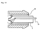
- the interior coating device 4 has substantially the same basic construction as a conventional device, but a special holder 50 having an inner diameter which is equal to the length of the major axis of the oval tube T plus 0.1 mm to 0.5 mm is required. Since a spray gun 51 is spaced different distances from the tube on the diametrically opposite sides of the major axis of the tube and on the diametrically opposite sides of the minor axis of the tube, the coating is liable to be uneven. Therefore, the spray angle is preferably adjusted such that an interior coating agent is sprayed more directly toward the distal edge (shoulder) of the tube, as compared with the conventional circular tube. An epoxy paint or a phenol paint is usable as the interior coating agent.
- Examples of the epoxy paint include an epoxy-amino resin prepared by adding a melamine resin to an epoxy resin, and an epoxy-phenol resin prepared by adding a thermosetting phenol resin to an epoxy resin.
- Examples of the phenol paint include a phenol resin prepared by modifying an alcohol-soluble phenol resin with a thermoplastic resin such as a butyral resin.
- the holder 50 is driven to be rotated at a high speed. While the spray gun 51 is retracted from a distal end (adjacent to the shoulder of the tube) with the aluminum tube being rotated together with the holder, the paint is sprayed for the painting of the interior surface.
- the paint spraying operation is preferably performed twice or more times for formation of a uniform coating film. It is preferred to perform the spraying operation at least once by means of a spray gun adapted for coating of the oval body and perform the spraying operation at least once by means of a spray gun adapted for coating of the shoulder and the mouth. Where a relatively thick coating film is to be uniformly formed, it is preferred to perform an intermediate drying operation at a predetermined temperature (e.g., at about 10°C) to evaporate a solvent after the first spraying operation, and then perform the second spraying operation.
- a predetermined temperature e.g., at about 10°C
- the prime coating printer 7, the offset printer 8 and the sealant applying device 10 are preferably modified for the formation of the oval tube. Techniques for other oval products such as plastic oval tubes may be used for the modification of these devices.
- the novel metal tube having an oval cross section. Since the body and the shoulder of the tube each have an oval cross section, the shoulder can be easily collapsed along the minor axis thereof.
- the conventional metal tube including the mouth, the shoulder and the body integrally formed has a disadvantage such that contents are likely to partly remain in the shoulder of the metal tube, the present invention eliminates this disadvantage. Since the metal tube has an oval shape, a multiplicity of such tubes can be efficiently stored by arranging the tubes in a proper direction. Further, the inventive metal tube has advantages as a metal tube and, at the same time, has an increased volume because of the oval cross section of the body thereof. In addition, the metal tube with a painted outer surface has an excellent appearance comparable to that of a plastic tube.
- the profile extrusion for the formation of the oval tube is achieved by optimizing the shapes of the die and the punch, and the material loss is reduced to a level comparable to that caused in the case where the conventional circular tube is formed by the impact press.
- the punch is constituted essentially by the circular cylindrical punch shaft and the punch head having an oval cross section
- the taper surfaces provided on the proximal peripheral portions of the punch head on the diametrically opposite sides of the major axis of the punch head and connected to the outer peripheral surface of the punch shaft makes it possible to smoothly release the tube.
Landscapes
- Engineering & Computer Science (AREA)
- Mechanical Engineering (AREA)
- Extrusion Of Metal (AREA)
- Forging (AREA)
- Tubes (AREA)
- Press Drives And Press Lines (AREA)
Claims (17)
- Dispositif de production d'un tube métallique à section ovale comprenant:- un dispositif d'extrusion à l'impact (1) qui est adapté pour extruder à l'impact un cylindre métallique en forme de disque (21) pour former un tube métallique (T) incluant intégralement une épaule et un corps qui sont tous les deux de section ovale et une bouche,- où le dispositif d'extrusion à l'impact (1) comprend un poinçon colonne (13) ayant un axe, une matrice de presse (14), et un stripper (15) pourvu autour le poinçon (13) d'une manière mobile en direction axiale,- où le poinçon (13) comprend un arbre de poinçon (22), une tête de poinçon (23) pourvue à une extrémité distale de l'arbre (22) et incluant une épaule de poinçon (25), qui présente une surface extérieure à section ovale et un tenon de poinçon (39),- où la matrice (14) comprend une base de matrice (18) avec une bouche définissant la surface (19) ; et un anneau de matrice (17) qui présente une surface périphérique intérieure ayant une section ovale, qui retient le cylindre métallique (21) là dedans,- où l'épaule de poinçon (25) est insérable dans l'anneau de matrice (17) et le tenon de poinçon (39)) est insérable dans la bouche définissant la surface (19);caractérisé en ce que la bouche du tube métallique (T) à extruder présente la section circulaire,- le tenon de poinçon (39) présente une section circulaire, et le poinçon (13) comprend de plus une première surface conique (26) à section ovale qui présente un diamètre décroissant progressivement à partir de l'épaule de poinçon (25) vers le tenon de poinçon (39),- la surface définissant la bouche (19) de la matrice (14) est circulaire et la matrice (14) comprend de plus une surface conique (18) connectant la surface définissant la bouche (19) e t la surface périphérique intérieure de l'anneau de matrice (17); et- le dispositif de production comprend de plus un dispositif de coupe (2) qui coupe une portion de bord (E) du corps ovale du tube (T) formée par le dispositif d'extrusion à l'impact (1) par une opération de tournage.
- Dispositif de production d'un tube métallique à section ovale comme expliqué dans la revendication 1,- où les lignes de génération de la première surface conique (26) sur les côtés diamétralement opposés d'un axe majeur de la première surface conique (26) forment chacune un angle de pas plus petit de 55 degrés et pas plus de 65 degrés à l'égard de l'axe du poinçon (13),- où les lignes de génération de la première surface conique (26) sur les côtés diamétralement opposés d'un axe mineur de la première surface conique (26) forment chacune un angle de pas plus petit de 43 degrés et pas plus de 53 degrés à l'égard de l'axe du poinçon (13),- où la surface extérieure de l'épaule (25) et la surface périphérique intérieure de l'anneau de matrice (17) sont chacune dimensionnée de sorte que le rapport dimensionnel d'un axe mineur à un axe majeur de celle-ci ne soit plus petit de 0,5 et plus de 0,9.
- Dispositif de production d'un tube métallique à section ovale comme expliqué dans la revendication 1,- où l'arbre de poinçon (22) présente une forme cylindrique circulaire,- où l'axe mineur de la base de la tête de poinçon (23) présente une longueur égale à un diamètre de l'arbre de poinçon (22),- où la tête de poinçon (23) présente la seconde surface conique (27) définie respectivement sur les portions périphériques proximales de celle-ci sur les côtés diamétralement opposés d'un axe majeur de celle-ci et connectée à une surface périphérique extérieure de l'arbre de poinçon (22).- où les lignes de génération de la seconde surface conique (27) sur les côtés diamétralement opposés de l'axe majeur de la tête du poinçon (23) forment chacune un angle de pas plus petit de 10 degrés et pas plus de 60 degrés à l'égard de l'axe du poinçon (13).
- Dispositif de production d'un tube métallique à section ovale comme expliqué dans la revendication 1,- où le stripper (15) comprend une pluralité de segments (28) arrangés sur la circonférence, les segments (28) étant chacun radialement mobile,- où les bords distaux des surfaces périphériques intérieures des segments (28) ont chacun une forme en arc de cercle qui correspond à la forme périphérique extérieure de la base de la tête de poinçon (23).
- Dispositif de production d'un tube métallique à section ovale comme expliqué dans la revendication 4, comprenant de plus un élément de précontrainte qui tient les segments respectifs précontraints radialement vers l'intérieur.
- Dispositif de production d'un tube métallique à section ovale comme expliqué dans la revendication 1,- où le dispositif de coupe (2) comprend un mandrin (40) sur lequel en utilisation le tube métallique (T) formé par le dispositif d'extrusion à l'impact (1) est ajusté, le mandrin (40) étant capable de rotation autour un axe de celui, et un outil de coupe (42) qui en utilisation coupe la portion de bord (E) du tube métallique (T) ajusté sur le mandrin (40),- où le mandrin (40) comprend une portion conique (44) ayant une forme de tronc de cône qui présente un diamètre décroissant progressivement vers une extrémité distale de celle-ci,- où une portion proximale de la portion conique (44) présente un diamètre plus grand qu'une longueur d'un axe majeur d'une surface périphérique intérieure du corps du tube métallique (T)- où la portion de bord (E) du tube métallique (T) est en utilisation coupée à une position axialement moyenne de la portion conique (44) par l'outil de coupe (42),- où la portion de bord (E) du tube métallique (T) ajustée sur le mandrin (42) est en utilisation arrondie dans une forme circulaire par la portion conique (44),- où le tube métallique (T) ayant la portion de bord arrondie (E) est en utilisation tourné à l'égard de l'outil de coupe (42) par la rotation du mandrin (40), de cette manière la portion de bord (E) du tube (T) est coupée sur circonférence par l'outil de coupe (42).
- Dispositif de production d'un tube métallique à section ovale comme expliqué dans la revendication 6,- où la portion conique (44) du mandrin (40) présente une cannelure (48) pourvue sur une surface périphérique extérieure de celle-ci en association avec l'outil de coupe (42) quand s'étendant sur la circonférence de celle-ci.
- Dispositif de production d'un tube métallique à section ovale comme expliqué dans la revendication 6, comprenant de plus :- un dispositif de normalisation (3) qui est adapté pour normaliser le tube métallique (T) formé et durci par l'extrusion à l'impact formé par le dispositif d'extrusion à l'impact (1) ; et- un dispositif de restauration qui est adapté pour restaurer la portion de bord (E) du tube (T) déformée dans la forme circulaire par le mandrin (40) du dispositif de coupe (2) dans la forme ovale,- où le dispositif de normalisation (3) normalise en utilisation le tube métallique (T) avec la portion de bord (E) du tube métallique (T) restaurée dans la forme ovale.
- Un procédé de production d'un tube métallique (T) à section ovale comprenant les étapes de :- extruder à l'impact un cylindre métallique en forme de disque (21) pour former un tube métallique (T) incluant intégralement une épaule et un corps qui sont tous les deux de section ovale et une bouche,- où l'étape d'extrusion à l'impact est réalisée par un dispositif d'extrusion à l'impact (1) incluant un poinçon colonne (13) ayant un axe, une matrice de presse (14), et un stripper (15) pourvu autour le poinçon (13) d'une manière mobile en direction axiale,- où le poinçon (13) comprend un arbre de poinçon (22), une tête de poinçon (23) pourvue à une extrémité distale de l'arbre (22) et incluant une épaule de poinçon (25), qui présente une surface extérieure à section ovale et un tenon de poinçon (39),- où la matrice (14) comprend une base de matrice (16) avec une bouche définissant la surface (19) et un anneau de matrice (17) qu i présente une surface périphérique intérieure ayant une section ovale, qui retient le cylindre métallique (21) là dedans,- où l'épaule de poinçon (25) est inséré dans l'anneau de matrice (17) et le tenon de poinçon (39)) est inséré dans la surface définissant la bouche (19) ;caractérisé en ce que la bouche du tube métallique (T) présente la section circulaire,- le tenon de poinçon (39) présente une section circulaire, et le poinçon (13) comprend de plus une première surface conique (26) ayant une section ovale qui présente un diamètre décroissant progressivement à partir de l'épaule de poinçon (25) vers le tenon de poinçon (39),- la surface définissant la bouche (19) de la matrice (14) est circulaire, et la matrice (14) comprend de plus une surface conique (18) connectant la surface définissant la bouche (19) et la surface périphérique intérieure de l'anneau de matrice (17) ; et- le procédé comprend de plus une étape de coupe (2) d'une portion de bord (E) du corps ovale du tube (T) formée par le dispositif d'extrusion à l'impact (1) par une opération de tournage.
- Un procédé de production d'un tube métallique (T) à section ovale comme expliqué dans la revendication 9,- où les lignes de génération de la première surface conique (26) sur les côtés diamétralement opposés d'un axe majeur de la première surface conique (26) forment chacune un angle de pas plus petit de 55 degrés et pas plus de 65 degrés à l'égard de l'axe du poinçon (13),- où les lignes de génération de la première surface conique (26) sur les côtés diamétralement opposés d'un axe mineur de la première surface conique (26) forment chacune un angle de pas plus petit de 43 degrés et pas plus de 53 degrés à l'égard de l'axe du poinçon (13),- où la surface extérieure de l'épaule (25) et la surface périphérique intérieure de l'anneau de matrice (17) sont chacune dimensionnée de sorte que le rapport dimensionnel d'un axe mineur à un axe majeur de celui soit pas plus petit de 0,5 et pas plus de 0,9.
- Un procédé de production d'un tube métallique (T) à section ovale comme expliqué dans la revendication 9,- où l'arbre de poinçon (22) présente une forme cylindrique circulaire,- où l'axe mineur de la base de la tête de poinçon (23) présente une longueur égale à un diamètre de l'arbre de poinçon (22),- où la tête de poinçon (23) présente la seconde surface conique (27) définie respectivement sur les portions périphériques proximales de celle-ci sur les côtés diamétralement opposés d'un axe majeur de celle-ci et connectée à une surface périphérique extérieure de l'arbre de poinçon (22).- où les lignes de génération de la seconde surface conique (27) sur les côtés diamétralement opposés de l'axe majeur de la tête du poinçon (23) forment chacune un angle de pas plus petit de 10 degrés et pas plus de 60 degrés à l'égard de l'axe du poinçon (13).
- Un procédé de production d'un tube métallique (T) à section ovale comme expliqué dans la revendication 9,- où le stripper (15) comprend une pluralité de segments (28) arrangés sur la circonférence, les segments (28) étant chacun radialement mobile,- où les bords distaux des surfaces périphériques intérieures des segments (28) ont chacun une forme en arc de cercle qui corresponde à la forme périphérique extérieure de la base de la tête de poinçon (23).- où une portion proximale du tube métallique (T) formée pour être ajustée autour le poinçon (13) par l'extrusion à l'impact est poussée vers une extrémité distale du poinçon (13) par le stripper (15), de cette manière le tube métallique (T) est délivré du poinçon (13).
- Un procédé de production d'un tube métallique (T) à section ovale comme expliqué dans la revendication 12, où les segments (28) sont précontraints radialement vers l'intérieur pendant la délivrance.
- Un procédé de production d'un tube métallique (T) à section ovale comme expliqué dans la revendication 9, où la portion de bord (E) du tube métallique (T) qui est formée et durcie dans l'étape d'extrusion à l'impact est déformée dans une forme circulaire et, après que la portion de bord (E) est restaurée dans une forme ovale, le tube métallique (T) est normalisé à l'étape de coupe.
- Un procédé de production d'un tube métallique (T) à section ovale comme expliqué dans la revendication 9,- où l'étape de coupe est réalisée par un dispositif de coupe (2) incluant un mandrin (40) sur lequel le tube métallique (T) formé dans l'étape d'extrusion à l'impact est ajusté, le mandrin (40) étant capable de rotation autour un axe de celui, et un outil de coupe (42) qui coupe la portion de bord (E) du tube métallique (T) ajusté sur le mandrin (40),- où le mandrin (40) comprend une portion conique (44) ayant une forme de tronc de cône qui présente un diamètre décroissant progressivement vers une extrémité distale de celle-ci,- où une portion proximale de la portion conique (44) présente un diamètre plus grand qu'une longueur d'un axe majeur d'une surface périphérique intérieure du corps du tube métallique (T).- où la portion de bord (E) du tube métallique (T) est coupée à une portion axialement moyenne de la portion conique (44) par l'outil de coupe (42),- où la portion de bord (E) du tube métallique (T) ajustée sur le mandrin (40) est arrondie dans une forme circulaire par la portion conique (44),- où le tube métallique (T) ayant la portion de bord (E) arrondie est tourné à l'égard de l'outil de coupe (42) par la rotation du mandrin (40), de cette manière la portion de bord (E) du tube (T) est coupée sur circonférence par l'outil de coupe (42).
- Un procédé de production d'un tube métallique (T) à section ovale comme expliqué dans la revendication 15, où la portion conique (44) du mandrin (40) présente une cannelure (48) pourvue dans une surface périphérique extérieure de celle-ci en association avec l'outil de coupe (42) quand s'étendant sur la circonférence de celle-ci, de cette manière à l'outil de coupe (42) est permis d'entrer dans la cannelure (46) pendant le coupage.
- Un procédé de production d'un tube métallique (T) à section ovale comme expliqué dans la revendication 15, comprenant de plus les étapes de :- normaliser le tube métallique (T) qui est formé et durci par l'extrusion à l'impact réalisée par le dispositif d'extrusion à l'impact (1) ; et- restaurer la portion de bord (E) du tube (T) déformé dans la forme circulaire par le mandrin (40) du dispositif de coupe (2) dans la forme ovale,- où l'étape de normalisation suivit à l'étape de restauration.
Applications Claiming Priority (3)
| Application Number | Priority Date | Filing Date | Title |
|---|---|---|---|
| JP2002218381 | 2002-07-26 | ||
| JP2002218381A JP4145594B2 (ja) | 2002-07-26 | 2002-07-26 | 断面楕円形金属チューブ、及び、その製造装置並びに製造方法 |
| PCT/JP2003/009419 WO2004011167A1 (fr) | 2002-07-26 | 2003-07-25 | Dispositif de production d'un tube metallique a section ovale et procede de production associe |
Publications (3)
| Publication Number | Publication Date |
|---|---|
| EP1586389A1 EP1586389A1 (fr) | 2005-10-19 |
| EP1586389A4 EP1586389A4 (fr) | 2007-10-17 |
| EP1586389B1 true EP1586389B1 (fr) | 2008-10-08 |
Family
ID=31184677
Family Applications (1)
| Application Number | Title | Priority Date | Filing Date |
|---|---|---|---|
| EP03771321A Expired - Lifetime EP1586389B1 (fr) | 2002-07-26 | 2003-07-25 | Dispositif de production d'un tube metallique a section ovale et procede de production associe |
Country Status (6)
| Country | Link |
|---|---|
| US (1) | US7219522B2 (fr) |
| EP (1) | EP1586389B1 (fr) |
| JP (1) | JP4145594B2 (fr) |
| AU (1) | AU2003255157A1 (fr) |
| DE (1) | DE60324030D1 (fr) |
| WO (1) | WO2004011167A1 (fr) |
Cited By (1)
| Publication number | Priority date | Publication date | Assignee | Title |
|---|---|---|---|---|
| US11908989B2 (en) | 2016-11-04 | 2024-02-20 | Schuler Pressen Gmbh | Method and device for producing a prismatic battery cell container |
Families Citing this family (16)
| Publication number | Priority date | Publication date | Assignee | Title |
|---|---|---|---|---|
| WO2007028865A1 (fr) * | 2005-09-02 | 2007-03-15 | Thermagen, Sa | Dispositif de refrigeration |
| KR100845421B1 (ko) | 2007-01-17 | 2008-07-10 | 주식회사화신 | 자동차의 크로스멤버용 컵의 제조방법 |
| ATE512730T1 (de) * | 2007-06-29 | 2011-07-15 | Gkn Driveline Int Gmbh | Vorrichtung und verfahren zum axialumformen von langgestreckten hohlkörpern |
| JP2009067401A (ja) * | 2007-09-11 | 2009-04-02 | Kansai Tube Kk | 金属チューブ容器及びその製造方法 |
| US8073524B2 (en) * | 2007-11-08 | 2011-12-06 | Imris Inc. | Control of magnetic field homogeneity in movable MRI scanning system |
| JP2012240723A (ja) * | 2011-05-20 | 2012-12-10 | Takeuchi Press Ind Co Ltd | チューブ容器 |
| DE102011080769A1 (de) * | 2011-08-10 | 2013-02-14 | Mall + Herlan Gmbh | Effektive Produktionslinie für Aerosoldosen |
| JP5929619B2 (ja) | 2012-08-10 | 2016-06-08 | 富士ゼロックス株式会社 | 筒状部材 |
| CN103042061B (zh) * | 2013-01-08 | 2015-04-01 | 青岛勤德索具有限公司 | 智能化管内径变径系统及管内径变径方法 |
| CA2944672A1 (fr) * | 2014-04-11 | 2015-10-15 | iMOLZ, LLC | Recipient sous pression metallique de forme non arrondie et son procede de fabrication |
| KR101432776B1 (ko) * | 2014-05-09 | 2014-09-22 | 린노알미늄 주식회사 | 임팩트 프레스기의 성형품 분리장치 |
| CN112620372B (zh) * | 2020-12-23 | 2022-05-24 | 太原理工大学 | 连续差速挤压制备弱基面织构镁合金板带材的模具及方法 |
| CN113102599B (zh) * | 2021-04-26 | 2024-12-10 | 勋龙智造精密应用材料(苏州)股份有限公司 | 一种用于模具封水机构的冲击头 |
| CN114770138B (zh) * | 2022-05-10 | 2025-06-17 | 沈阳泰德自动化设备有限公司 | 一种方型薄壁储能电池壳卧式挤压成型生产线 |
| KR20250023663A (ko) * | 2023-08-10 | 2025-02-18 | 삼성에스디아이 주식회사 | 각형 캔 제조 장치 |
| DE102023129381B3 (de) * | 2023-10-25 | 2024-11-07 | Linhardt Gmbh & Co. Kg | Vorrichtung zur Herstellung kleinvolumiger Tubenverpackungsrohlinge |
Family Cites Families (10)
| Publication number | Priority date | Publication date | Assignee | Title |
|---|---|---|---|---|
| US2162776A (en) * | 1936-11-20 | 1939-06-20 | Sun Tube Corp | Apparatus for and method of making thin metal containers |
| US2161752A (en) * | 1938-02-16 | 1939-06-06 | Victor Metal Products Corp | Stripper for collapsible tube extruding presses |
| US2533942A (en) * | 1948-05-06 | 1950-12-12 | Western Electric Co | Extruding apparatus |
| US2789344A (en) * | 1951-04-23 | 1957-04-23 | American Radiator & Standard | Method of cold shaping tubular steel articles and product |
| US2979195A (en) * | 1956-09-26 | 1961-04-11 | Procter & Gamble | Method of and apparatus for extruding metal collapsible tubes |
| US3415098A (en) * | 1966-03-08 | 1968-12-10 | Gen Electric | Method of extruding capacitor cases |
| BE791879A (fr) * | 1971-11-25 | 1973-05-24 | Scal Gp Condit Aluminium | Procede de fabrication de tubes souples coniques |
| JPS53133570A (en) * | 1977-04-28 | 1978-11-21 | Kyodo Printing Co Ltd | Manufacturing method of compound tube |
| JPH0265447A (ja) | 1988-08-31 | 1990-03-06 | Matsushita Electric Ind Co Ltd | 無線装置 |
| JPH0543958Y2 (fr) * | 1988-11-01 | 1993-11-08 |
-
2002
- 2002-07-26 JP JP2002218381A patent/JP4145594B2/ja not_active Expired - Fee Related
-
2003
- 2003-07-25 AU AU2003255157A patent/AU2003255157A1/en not_active Abandoned
- 2003-07-25 DE DE60324030T patent/DE60324030D1/de not_active Expired - Lifetime
- 2003-07-25 US US10/522,217 patent/US7219522B2/en not_active Expired - Fee Related
- 2003-07-25 EP EP03771321A patent/EP1586389B1/fr not_active Expired - Lifetime
- 2003-07-25 WO PCT/JP2003/009419 patent/WO2004011167A1/fr not_active Ceased
Cited By (1)
| Publication number | Priority date | Publication date | Assignee | Title |
|---|---|---|---|---|
| US11908989B2 (en) | 2016-11-04 | 2024-02-20 | Schuler Pressen Gmbh | Method and device for producing a prismatic battery cell container |
Also Published As
| Publication number | Publication date |
|---|---|
| EP1586389A4 (fr) | 2007-10-17 |
| AU2003255157A1 (en) | 2004-02-16 |
| WO2004011167A1 (fr) | 2004-02-05 |
| JP4145594B2 (ja) | 2008-09-03 |
| DE60324030D1 (de) | 2008-11-20 |
| JP2004058087A (ja) | 2004-02-26 |
| US20050247097A1 (en) | 2005-11-10 |
| US7219522B2 (en) | 2007-05-22 |
| EP1586389A1 (fr) | 2005-10-19 |
Similar Documents
| Publication | Publication Date | Title |
|---|---|---|
| US7219522B2 (en) | Oval cross section metal tube producing device and producing method | |
| EP2871022B1 (fr) | Outil de galetage | |
| US7555927B2 (en) | Bottle-shaped can manufacturing method and bottle-shaped can | |
| EP3256747B1 (fr) | Rivet auto-poinçonneur et procédé de production d'un assemblage riveté par poinçonnage | |
| EP2000688B1 (fr) | Procédé de production d'un anneau intérieur forgé pour un joint universel à vitesse constante et son dispositif de fabrication | |
| CN100391672C (zh) | 系紧螺钉的旋钮和套环的制造方法 | |
| WO1996016754A1 (fr) | Procede de formation d'un goulot sur un recipient metallique extrude par choc | |
| KR20060092202A (ko) | 보틀 캔 제조장치 | |
| JP4149191B2 (ja) | 金属製ボトル缶の製造方法および製造装置 | |
| KR20040058090A (ko) | 캔 본체를 확장시켜 성형하는 장치 및 방법 | |
| US20210154728A1 (en) | Manufacturing Process, Tool Stand, and Drill Bit | |
| US4967583A (en) | Method of manufacturing extruded seamless hollow materials | |
| JPH0760336A (ja) | 中空ステアリングシャフトの製造方法 | |
| JP2007229807A (ja) | 金属製ボトル缶の製造方法および製造装置 | |
| JP6887363B2 (ja) | 缶の製造方法 | |
| EP0110127B1 (fr) | Procédé pour fabriquer un anneau de cuvelage pour commutateur | |
| US11951527B2 (en) | Method for producing a ball raceway on a workpiece and a ball screw nut having a ball raceway thus produced | |
| US20110185782A1 (en) | Flow form tool mandrel | |
| DE102023121770B3 (de) | Verfahren zur Herstellung einer Rotorhohlwelle | |
| EP4547570A1 (fr) | Moyen de fermeture comprenant un filet en métal pour fermer un contenant et son procédé de production | |
| US3733880A (en) | Apparatus for and method of facilitating the stripping of cans from a punch and the article formed thereby | |
| KR20220147763A (ko) | 스티어링 샤프트 및 그 제조방법 | |
| EP1285705A2 (fr) | Méthode et dispositif pour le calibrage des profiles creux ou des corps creux | |
| US20030005739A1 (en) | Method and apparatus for producing a rotationally symmetric component | |
| US20030200781A1 (en) | Method of tensile flow forming |
Legal Events
| Date | Code | Title | Description |
|---|---|---|---|
| PUAI | Public reference made under article 153(3) epc to a published international application that has entered the european phase |
Free format text: ORIGINAL CODE: 0009012 |
|
| 17P | Request for examination filed |
Effective date: 20050126 |
|
| AK | Designated contracting states |
Kind code of ref document: A1 Designated state(s): AT BE BG CH CY CZ DE DK EE ES FI FR GB GR HU IE IT LI LU MC NL PT RO SE SI SK TR |
|
| AX | Request for extension of the european patent |
Extension state: AL LT LV MK |
|
| DAX | Request for extension of the european patent (deleted) | ||
| RBV | Designated contracting states (corrected) |
Designated state(s): DE FR GB |
|
| A4 | Supplementary search report drawn up and despatched |
Effective date: 20070918 |
|
| RIC1 | Information provided on ipc code assigned before grant |
Ipc: B21C 23/21 20060101ALI20070912BHEP Ipc: B21C 25/02 20060101ALI20070912BHEP Ipc: B21C 23/18 20060101AFI20040218BHEP |
|
| 17Q | First examination report despatched |
Effective date: 20071121 |
|
| GRAP | Despatch of communication of intention to grant a patent |
Free format text: ORIGINAL CODE: EPIDOSNIGR1 |
|
| GRAS | Grant fee paid |
Free format text: ORIGINAL CODE: EPIDOSNIGR3 |
|
| GRAA | (expected) grant |
Free format text: ORIGINAL CODE: 0009210 |
|
| AK | Designated contracting states |
Kind code of ref document: B1 Designated state(s): DE FR GB |
|
| REG | Reference to a national code |
Ref country code: GB Ref legal event code: FG4D |
|
| REF | Corresponds to: |
Ref document number: 60324030 Country of ref document: DE Date of ref document: 20081120 Kind code of ref document: P |
|
| PLBE | No opposition filed within time limit |
Free format text: ORIGINAL CODE: 0009261 |
|
| STAA | Information on the status of an ep patent application or granted ep patent |
Free format text: STATUS: NO OPPOSITION FILED WITHIN TIME LIMIT |
|
| 26N | No opposition filed |
Effective date: 20090709 |
|
| PGFP | Annual fee paid to national office [announced via postgrant information from national office to epo] |
Ref country code: GB Payment date: 20120723 Year of fee payment: 10 |
|
| PGFP | Annual fee paid to national office [announced via postgrant information from national office to epo] |
Ref country code: DE Payment date: 20120721 Year of fee payment: 10 Ref country code: FR Payment date: 20120809 Year of fee payment: 10 |
|
| GBPC | Gb: european patent ceased through non-payment of renewal fee |
Effective date: 20130725 |
|
| REG | Reference to a national code |
Ref country code: DE Ref legal event code: R119 Ref document number: 60324030 Country of ref document: DE Effective date: 20140201 |
|
| REG | Reference to a national code |
Ref country code: FR Ref legal event code: ST Effective date: 20140331 |
|
| PG25 | Lapsed in a contracting state [announced via postgrant information from national office to epo] |
Ref country code: DE Free format text: LAPSE BECAUSE OF NON-PAYMENT OF DUE FEES Effective date: 20140201 Ref country code: GB Free format text: LAPSE BECAUSE OF NON-PAYMENT OF DUE FEES Effective date: 20130725 |
|
| PG25 | Lapsed in a contracting state [announced via postgrant information from national office to epo] |
Ref country code: FR Free format text: LAPSE BECAUSE OF NON-PAYMENT OF DUE FEES Effective date: 20130731 |