EP1585939B1 - Attitude change kalman filter measurement apparatus and method - Google Patents
Attitude change kalman filter measurement apparatus and method Download PDFInfo
- Publication number
- EP1585939B1 EP1585939B1 EP04700822.2A EP04700822A EP1585939B1 EP 1585939 B1 EP1585939 B1 EP 1585939B1 EP 04700822 A EP04700822 A EP 04700822A EP 1585939 B1 EP1585939 B1 EP 1585939B1
- Authority
- EP
- European Patent Office
- Prior art keywords
- signal
- attitude
- navigation
- kalman filter
- attitude change
- Prior art date
- Legal status (The legal status is an assumption and is not a legal conclusion. Google has not performed a legal analysis and makes no representation as to the accuracy of the status listed.)
- Expired - Lifetime
Links
- 206010034719 Personality change Diseases 0.000 title claims description 18
- 238000000034 method Methods 0.000 title claims description 15
- 238000005259 measurement Methods 0.000 title description 33
- 230000008859 change Effects 0.000 claims description 21
- 238000012937 correction Methods 0.000 claims description 14
- 238000001914 filtration Methods 0.000 claims description 4
- 230000003111 delayed effect Effects 0.000 claims 3
- 239000013598 vector Substances 0.000 description 24
- 239000011159 matrix material Substances 0.000 description 22
- 238000010586 diagram Methods 0.000 description 3
- 238000005516 engineering process Methods 0.000 description 3
- 230000001133 acceleration Effects 0.000 description 2
- 238000013459 approach Methods 0.000 description 2
- 238000004364 calculation method Methods 0.000 description 2
- 230000010354 integration Effects 0.000 description 2
- 230000008569 process Effects 0.000 description 2
- 238000005295 random walk Methods 0.000 description 2
- 239000007787 solid Substances 0.000 description 2
- 235000015842 Hesperis Nutrition 0.000 description 1
- 235000012633 Iberis amara Nutrition 0.000 description 1
- 241000667869 Psix Species 0.000 description 1
- 230000008901 benefit Effects 0.000 description 1
- 238000004422 calculation algorithm Methods 0.000 description 1
- 238000010276 construction Methods 0.000 description 1
- 230000007246 mechanism Effects 0.000 description 1
- 238000012545 processing Methods 0.000 description 1
- 230000000644 propagated effect Effects 0.000 description 1
- 238000012552 review Methods 0.000 description 1
- 230000035945 sensitivity Effects 0.000 description 1
- 230000009466 transformation Effects 0.000 description 1
Images
Classifications
-
- G—PHYSICS
- G01—MEASURING; TESTING
- G01C—MEASURING DISTANCES, LEVELS OR BEARINGS; SURVEYING; NAVIGATION; GYROSCOPIC INSTRUMENTS; PHOTOGRAMMETRY OR VIDEOGRAMMETRY
- G01C21/00—Navigation; Navigational instruments not provided for in groups G01C1/00 - G01C19/00
- G01C21/10—Navigation; Navigational instruments not provided for in groups G01C1/00 - G01C19/00 by using measurements of speed or acceleration
- G01C21/12—Navigation; Navigational instruments not provided for in groups G01C1/00 - G01C19/00 by using measurements of speed or acceleration executed aboard the object being navigated; Dead reckoning
- G01C21/16—Navigation; Navigational instruments not provided for in groups G01C1/00 - G01C19/00 by using measurements of speed or acceleration executed aboard the object being navigated; Dead reckoning by integrating acceleration or speed, i.e. inertial navigation
- G01C21/183—Compensation of inertial measurements, e.g. for temperature effects
- G01C21/188—Compensation of inertial measurements, e.g. for temperature effects for accumulated errors, e.g. by coupling inertial systems with absolute positioning systems
-
- G—PHYSICS
- G01—MEASURING; TESTING
- G01C—MEASURING DISTANCES, LEVELS OR BEARINGS; SURVEYING; NAVIGATION; GYROSCOPIC INSTRUMENTS; PHOTOGRAMMETRY OR VIDEOGRAMMETRY
- G01C21/00—Navigation; Navigational instruments not provided for in groups G01C1/00 - G01C19/00
- G01C21/10—Navigation; Navigational instruments not provided for in groups G01C1/00 - G01C19/00 by using measurements of speed or acceleration
- G01C21/12—Navigation; Navigational instruments not provided for in groups G01C1/00 - G01C19/00 by using measurements of speed or acceleration executed aboard the object being navigated; Dead reckoning
- G01C21/16—Navigation; Navigational instruments not provided for in groups G01C1/00 - G01C19/00 by using measurements of speed or acceleration executed aboard the object being navigated; Dead reckoning by integrating acceleration or speed, i.e. inertial navigation
- G01C21/165—Navigation; Navigational instruments not provided for in groups G01C1/00 - G01C19/00 by using measurements of speed or acceleration executed aboard the object being navigated; Dead reckoning by integrating acceleration or speed, i.e. inertial navigation combined with non-inertial navigation instruments
- G01C21/1654—Navigation; Navigational instruments not provided for in groups G01C1/00 - G01C19/00 by using measurements of speed or acceleration executed aboard the object being navigated; Dead reckoning by integrating acceleration or speed, i.e. inertial navigation combined with non-inertial navigation instruments with electromagnetic compass
Definitions
- the present invention relates generally to a method and apparatus for correction of bias errors in a navigation system, and in particular to correction of bias errors in an inertial navigation system through the use of change in attitude measurements processed by a Kalman Filter.
- Inertial navigation is based on systems first built using gyros and accelerometers located on a moving platform or gimbal, which required very complicated technical and power consuming constructions that were prone to failure. Later on, solid state solutions have been realized by using only discrete integrated electro-mechanical or electro-optical sensors attached directly to the vehicle or strapdown. These solid state systems have minimal moving parts, and consist of laser-gyros, mechanical accelerometers and/or integrated gyros and accelerometers manufactured using MEMS (Micro Electro-Mechanical System) technology.
- MEMS Micro Electro-Mechanical System
- Inertial navigation systems are used in a wide variety of applications, including civil and military aviation, cruise missiles, submarines and space technology. According to these areas of operation, the entire system and all components have to be very precise and reliable. As a consequence, the costs for such a system are still relatively high and the size is not yet so small that it can be used for mobile roboting, wearable computing, automotive or consumer electronics.
- the main limitation of the system performance is due to the finite precision or accuracy of the sensors. For example, a continuous small error in acceleration will be integrated and results in a significant error in measured or predicted velocity. The velocity is then integrated a second time and will result in a position error. Therefore very precise sensors and error correction mechanisms are necessary for an accurate inertial navigation platform.
- the Kalman filter is a set of mathematical equations to provide a computational solution of the least-square method.
- Measurements are processed in the Kalman filter.
- the fact that the INS (inertial navigation system) is stationary (at a known position and heading, and zero velocity), information from a Global Positioning System (GPS), or information from another INS can be a measurement.
- the processing by the Kalman filter algorithm results in an estimate of the sensor errors (e.g. bias, scale-factor, non-linearity) which is used to correct the errors.
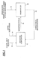
- FIG. 1 is a block diagram showing a navigation system 10, such as may be used in a vehicle or other moving body, which receives as inputs three signals from accelerometers 12 and three signals from gyros 14.
- the navigation system performs a strapdown navigation reference computation and provides as an output a navigation state signal (x) on 16.
- This navigation state signal is provided to a Kalman filter 18.
- an aiding source is connected (19) to the Kalman filter 18 is to provide a change in attitude measurement.
- the aiding source is the act of performing the measurements while the body is stationary.
- the Kalman filter 18 generates a signal on 20 that is returned to the navigation system 10, to thereby correct the bias errors which would otherwise cause significant errors in the navigation system's estimate of the vehicle's (or body's) movement.
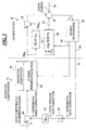
- FIG. 2 provides further detail of the present invention. Relevant additional details of the navigation portion 10 and of the Kalman filter portion 18 from Figure 1 are shown separated by a broken line 22.
- the navigation portion 10 has the input 14 for the gyro compensated incremental angles which is provided to an adder 24, that is in turn connected to a navigation computation portion 26 where the compensation is computed using information from a factory calibration or previous usages of the INS.
- the adder 24 also receives an input from a multiplier unit 29.
- the multiplier unit 28 scales the accumulated total bias rate correction from the summing unit 28 to incremental rates.
- the input to the multiplier unit 29 is a summing unit 28, which represents the Kalman filter's accumulated estimate of the gyro bias.
- the output of the adder 24 is provided to an attitude and heading reference function unit 30 in the navigation computation portion 26.
- the attitutude and heading reference function unit 30 produces a signal hdg(t k ) that is forwarded to the Kalman filter portion 18.
- the detail for the Kalman filter operation shown in Figure 2 shows only the heading error correction.
- the preferred embodiment of the invention has similar signal paths for pitch and roll correction which are the same, but these are omitted for clarity.
- the signal hdg(t k ) is sent to two sub-functions.
- the first sub-function is a delay unit 32 to delay by a factor of ⁇ t( kf )to generate a signal hdg(t (k-1) ).
- the two signals hdg(t k ) and hdg(t (k-1) ) are forwarded to an adder 34, with the signal hdg(t k ) being fed to the adding input of the adder 34 and the signal hdg(t (k-1) ) being fed to the subtracting input of the adder 34.
- the output of the adder is fed to the adding input of a further adder 36.
- This further adder 36 also has an input 38 connected to receive the observed heading change relative to an Earth over the time ⁇ t KF . In the case where the INS is at rest (stationary) this measurement is zero.
- the further adder has another subtracting input 40 which will be discussed later.
- the output of the further adder 36 is provided to the Kalman filter engine 42 as a signal y k .
- the Kalman filter operation will be discussed in detail hereinafter.
- the two outputs 44 and 46 of the Kalman filter engine 42 are an attitude (pitch and roll) and heading reset signal on 44 and a gyro bias reset rate signal on 46.
- the attitude and heading reset signal 44 is input to the attitude and heading function 30 and to an attitude and heading reset summer 48.
- the gyro bias rate resets signal 46 goes to the integrator 28.
- the integrator 28 integrates the gyro bias rate resets signal 46 over the time ⁇ t KF , the time period of the delay unit 32.
- the integrated output of the integrator 48 is fed to the subtracting input 40 of the further adder 36.
- the filter state vector is larger due to inclusion of other elements, but the six-element vector shown here suffices to describe the present invention.
- the matrix - ⁇ ⁇ n + ⁇ ⁇ n - C s n 0 0 depicts a 6x6 matrix, where each quadrant is a 3x3 matrix. That is, "0" represents a 3 by 3 matrix containing all zeroes, and the notation ⁇ + ⁇ defines a 3x3 matrix 0 - ⁇ z - ⁇ z ⁇ y + ⁇ y ⁇ z + ⁇ z 0 - ⁇ x - ⁇ x - ⁇ y - ⁇ y ⁇ x + ⁇ x 0
- An attitude or heading change measurement update is made wherein the Kalman filter's measurement is the difference between, on one hand, the inertially computed attitude or heading change of the KF update interval ⁇ t KF (less any attitude or heading resets applied by the filter during the interval) and, on the other hand, the externally observed attitude or heading change over the ⁇ t KF update interval.
- the externally observed attitude or heading change (at the aiding source) is taken to be zero.
- the externally observed attitude or heading change would be determined using other sensors, such as a compass INS, or magnetometer, a star tracker, etc. and provided to the input 38 as shown in Figure 2 .
- the attitude change measurement is identical except that is uses pitch or roll rather than heading and uses the pitch or roll components of the attitude matrix (C) and the state vector.
- the change in heading measurement is
- the post measurement update state vector X ⁇ k + can be used to reset the attitude and heading direction cosine matrix C s n and the gyro drift compensation parameters.
- the Kalman filter is modified to include a change in heading measurement. Once again only the change in heading measurement is shown for simplicity. A similar implementation is used for the level attitudes. The detailed software implementation is as follows for a heading change measurement:
- the present invention permits the inertial system to estimate bias errors, thereby permitting the use of poorer performing gyros, which cost less, yet achieve the performance of a INS containing better performing gyros.
- the present system can be used on a wide variety of vehicles. For example, robotic vehicles may benefit from the present system.
- the present system may also be used on missiles, rockets and other guided bodies.
- the present system augments the performance of a INS that relies on GPS (Global Positioning Satellite) systems, which are subject to being blocked by obstructions and which may be jammed whether or not the GPS is configured to provide attitude information.
- GPS Global Positioning Satellite
Landscapes
- Engineering & Computer Science (AREA)
- Radar, Positioning & Navigation (AREA)
- Remote Sensing (AREA)
- Physics & Mathematics (AREA)
- Automation & Control Theory (AREA)
- General Physics & Mathematics (AREA)
- Electromagnetism (AREA)
- Navigation (AREA)
- Gyroscopes (AREA)
- Position Fixing By Use Of Radio Waves (AREA)
Description
- The present invention relates generally to a method and apparatus for correction of bias errors in a navigation system, and in particular to correction of bias errors in an inertial navigation system through the use of change in attitude measurements processed by a Kalman Filter.
- Inertial navigation is based on systems first built using gyros and accelerometers located on a moving platform or gimbal, which required very complicated technical and power consuming constructions that were prone to failure. Later on, solid state solutions have been realized by using only discrete integrated electro-mechanical or electro-optical sensors attached directly to the vehicle or strapdown. These solid state systems have minimal moving parts, and consist of laser-gyros, mechanical accelerometers and/or integrated gyros and accelerometers manufactured using MEMS (Micro Electro-Mechanical System) technology.
- Inertial navigation systems (INS) are used in a wide variety of applications, including civil and military aviation, cruise missiles, submarines and space technology. According to these areas of operation, the entire system and all components have to be very precise and reliable. As a consequence, the costs for such a system are still relatively high and the size is not yet so small that it can be used for mobile roboting, wearable computing, automotive or consumer electronics.
- But navigation systems designed for these mobile applications require a very small and inexpensive implementation of such an INS. Industrial demand for low-cost sensors (in car airbag systems, for example) and recent progress in MEMS integration technology have led to sophisticated sensor products, which are now both small (single chips) and inexpensive.
- A body's actual spatial behavior / movement can be described with six parameters: three translatory (x-, y-, z-acceleration) and three rotatory components (x-, y-, z-angular velocity). To be able to define the movement of the body, three acceleration sensors and three gyros have to be put together on a platform in such a way that they form an orthogonal system either physically or mathematically. The distance translated and the angle the body has actually rotated can be obtained by integration of the individual translatory and rotatory components. Performing these calculations accurately and periodically enables the INS to trace its movement and to indicate its current position, velocity, pitch, roll, and heading.
- The main limitation of the system performance is due to the finite precision or accuracy of the sensors. For example, a continuous small error in acceleration will be integrated and results in a significant error in measured or predicted velocity. The velocity is then integrated a second time and will result in a position error. Therefore very precise sensors and error correction mechanisms are necessary for an accurate inertial navigation platform.
- A paper published by R. E. Kalman in 1960, "A New Approach to Linear Filtering and Prediction Problems", Transactions of the ASME-Journal of Basic Engineering, 82 (Series K): pages 35-45 (1960) described a recursive solution to the discrete-data linear filtering problem.
- The Kalman filter is a set of mathematical equations to provide a computational solution of the least-square method.
- In his book, "Stochastic Models, Estimation, and Control" vol. 1, ), Peter S. Maybeck discusses the Kalman filter as an optimal linear estimator.
- Greg Welch et al. review use of the Kalman filter in the area of autonomous or assisted navigation in the paper, "An Introduction to the Kalman Filter", UNC-Chapel Hill, TR 95-041, March 11,2002.
EP 1 059 509 - The present invention in its various aspects is as set out in the appended claims. The present invention provides an application of a Kalman filter to determine and remove gyro bias errors from an inertial navigation system. This implementation adds an attitude change measurement to the Kalman filter. This change may be made in the heading measurement and/or the level attitudes (pitch and roll), and provides the observability needed to estimate the gyro biases in the inertial system. For example, when the system is stationary it is undergoing zero change in heading, pitch, and roll relative to the earth. This contrasts with the conventional approach of using a known pitch, roll, and heading as the measurement for the Kalman filter.
- To improve the performance of the inertial sensors, a Kalman filter is employed to estimate the inertial sensors errors using measurements from a variety of sources.
- Measurements are processed in the Kalman filter. For example, the fact that the INS (inertial navigation system) is stationary (at a known position and heading, and zero velocity), information from a Global Positioning System (GPS), or information from another INS can be a measurement. The processing by the Kalman filter algorithm results in an estimate of the sensor errors (e.g. bias, scale-factor, non-linearity) which is used to correct the errors.
-
-
Figure 1 is a block diagram of the basic structure of the present system; and -
Figure 2 is functional block diagram showing the navigation system with the Kalman filter in greater detail. -
Figure 1 is a block diagram showing anavigation system 10, such as may be used in a vehicle or other moving body, which receives as inputs three signals fromaccelerometers 12 and three signals fromgyros 14. The navigation system performs a strapdown navigation reference computation and provides as an output a navigation state signal (x) on 16. This navigation state signal is provided to a Kalmanfilter 18. In some applications, an aiding source is connected (19) to the Kalmanfilter 18 is to provide a change in attitude measurement. In other applications, the aiding source is the act of performing the measurements while the body is stationary. The Kalmanfilter 18 generates a signal on 20 that is returned to thenavigation system 10, to thereby correct the bias errors which would otherwise cause significant errors in the navigation system's estimate of the vehicle's (or body's) movement. -
Figure 2 provides further detail of the present invention. Relevant additional details of thenavigation portion 10 and of the Kalmanfilter portion 18 fromFigure 1 are shown separated by a broken line 22. Thenavigation portion 10 has theinput 14 for the gyro compensated incremental angles which is provided to anadder 24, that is in turn connected to anavigation computation portion 26 where the compensation is computed using information from a factory calibration or previous usages of the INS. Theadder 24 also receives an input from amultiplier unit 29. Themultiplier unit 28 scales the accumulated total bias rate correction from thesumming unit 28 to incremental rates. The input to themultiplier unit 29 is asumming unit 28, which represents the Kalman filter's accumulated estimate of the gyro bias. The output of theadder 24 is provided to an attitude and headingreference function unit 30 in thenavigation computation portion 26. The attitutude and headingreference function unit 30 produces a signal hdg(tk) that is forwarded to the Kalmanfilter portion 18. - The detail for the Kalman filter operation shown in
Figure 2 shows only the heading error correction. The preferred embodiment of the invention has similar signal paths for pitch and roll correction which are the same, but these are omitted for clarity. In the Kalman filter function, the signal hdg(tk) is sent to two sub-functions. The first sub-function is adelay unit 32 to delay by a factor of Δt(kf)to generate a signal hdg(t(k-1)). The two signals hdg(tk) and hdg(t(k-1)) are forwarded to anadder 34, with the signal hdg(tk) being fed to the adding input of theadder 34 and the signal hdg(t(k-1)) being fed to the subtracting input of theadder 34. The output of the adder is fed to the adding input of afurther adder 36. Thisfurther adder 36 also has aninput 38 connected to receive the observed heading change relative to an Earth over the time ΔtKF. In the case where the INS is at rest (stationary) this measurement is zero. The further adder has anothersubtracting input 40 which will be discussed later. - The output of the
further adder 36 is provided to the Kalmanfilter engine 42 as a signal yk. The Kalman filter operation will be discussed in detail hereinafter. The twooutputs Kalman filter engine 42 are an attitude (pitch and roll) and heading reset signal on 44 and a gyro bias reset rate signal on 46. The attitude and headingreset signal 44 is input to the attitude and headingfunction 30 and to an attitude and headingreset summer 48. The gyro bias rate resets signal 46 goes to theintegrator 28. Theintegrator 28 integrates the gyro bias rate resets signal 46 over the time ΔtKF, the time period of thedelay unit 32. The integrated output of theintegrator 48 is fed to the subtractinginput 40 of thefurther adder 36. - In detail, the Kalman filter state vector x is defined,

where: - Ψn = the 3-dimensional vector (or 3-vector) representing the errors in the computed sensor-to-navigation frame tranformation matrix

- δωs = 3-vector representing the angular drift rate errors (or biases) of the three gyros in the sensor frame.
- Typically, in most attitude reference and inertial navigation applications, the filter state vector is larger due to inclusion of other elements, but the six-element vector shown here suffices to describe the present invention.
- The continuous time dynamical model is


where: - Ωn = the earth spin rate vector in the navigation frame,
- ρn = the transport rate vector in the navigation frame,
-

- ηδω = a three vector white noise process causing a random walk in the gyro drift error vector δωs , and
- ηARW = a three vector white noise process causing an "angle random walk" attitude/heading error growth.
- This can be written in partitioned form as

or in more compact form as
where (in this example) F is a 6x6 matrix and the x and η vectors are a 6x1 matrix. Note that the matrix

- The usual representation of the model is in discrete time:
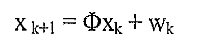
- where Φ is normally approximated by a series expansion in F, such as the second order approximation:

- The Kalman filter state vector is propagated between measurements as

- The error covariance propagation is

where Qk = E[WkWk T], Pk is the covariance matrix of the error in the estimate x̂k and P0 represents the initial uncertainty in the state vector elements. - An attitude or heading change measurement update is made wherein the Kalman filter's measurement is the difference between, on one hand, the inertially computed attitude or heading change of the KF update interval ΔtKF (less any attitude or heading resets applied by the filter during the interval) and, on the other hand, the externally observed attitude or heading change over the ΔtKF update interval.
- For a non-rotating IMU, the externally observed attitude or heading change (at the aiding source) is taken to be zero. For a rotating IMU platform, the externally observed attitude or heading change would be determined using other sensors, such as a compass INS, or magnetometer, a star tracker, etc. and provided to the
input 38 as shown inFigure 2 . - The following paragraph describes only the heading change measurement. The attitude change measurement is identical except that is uses pitch or roll rather than heading and uses the pitch or roll components of the attitude matrix (C) and the state vector. The change in heading measurement is
- yk = [(inertial heading at tk - inertial heading at tk-1- sum of all heading resets applied by the filter during the ΔtKF interval)] - [observed heading at tk - observed heading at tk-1]
- The KF measurement model is

- where Hk is the 1x6 measurement sensitivity matrix

- where

- of Cs n over the measurement ΔtKF interval, and
- Vk represents the noise in the heading change difference measurement, with E{vk 2} = Rk
- The filter's measurement update of the state vector and the covariance matrix proceed in the usual fashion. One implementation being



- There are many well known alternative methods in the published literature defining alternative implementations of the Kalman gain and covariance update calculations, all of which can be used in lieu of the above form, and are within the scope of the present invention.
- The post measurement update state vector X̂ k+ can be used to reset the attitude and heading direction cosine matrix Cs n and the gyro drift compensation parameters.
- One example of the the software implementation of the change in heading measurement to the Kalman filter is, as follows:
- The Kalman filter is modified to include a change in heading measurement. Once again only the change in heading measurement is shown for simplicity. A similar implementation is used for the level attitudes. The detailed software implementation is as follows for a heading change measurement:
 // Heading change measurement
 // Zero heading change measurement should only be enabled
 when the
 // platform is stationary.
 /
 if (first_pass)
 { first_pass = false;
 }
 else
 {filter.kalman.measurement_form[ATT[2]] =
 KF_UD_UTLLITIES::CONVENTIONAL;
 heading_change error = ANGLE_MATH::Plus or Minus_Pi
  (previous_heading_after_reset -
  passed_true_heading_prior_to_reset) ;
  delta_time = filter.time - previous_time;
  if ( (delta_time < filter.delta_time *2)
 && (filter.desired_mode = SMALL_AZIMUTH))
 {earth_plus_transport_rate =
 filter.average.transport_rate_LV
   + filter.average.earth_rate_LV;
 filter.kalman.Y.vector[ATT[2]] =
 heading_change_error.angle;
 filter.kalman.R.vector[ATT[2]] =
   filter.measurement_noise_stdv.ATT *
   filter.measurement noise stdv.ATT;
 fliter.kalman.H.matrix[ATT[2]] [PSIX] =
   -earth_plus_transport rate.vector[1] * delta_time;
 filter.kalman.H.matrix[ATT[2]][PSIY] =
   -earth_plus_transport rate.vector[0] * delta_time;
 filter.kalman.H.matrix[ATT[[2]][GBIASX] =
   -filter.average.body_to_lv_dcm.matrix[2][0] * delta_time;
 filter.kalman.H.matrix[ATT[2]][GBIASY] =
   -filter.average.body_to_lv_dcm.matrix[2][1] * delta_time;
   filter.kalman.H.matrix[ATT[2]]GBIASZ] =
   -filter.average.body_to_lv_dcm.matrix[2] [2] * delta_time;
 filter.kalman.measurement_available.vector[ATT[2]] = true;
 //
 // Increment and measurement validity data.
 //
 filter.measurement_validity.number_available =
   filter.measurement validity.number_available + 1;
 filter.measurement_validity.valid_id.
        vector[filter.measurement_validity.number_valid] =
 ATT[2]; filter.measurement_validity.number_valid =
   filter.measurement validity.number valid + 1;
   }
Claims (15)
- A navigation system for a body, comprising:inertial sensors having outputs from which signals (12, 14) are provided corresponding to inertial changes in the body; anda navigation computation portion (10, 26) connected to receive the signals from said inertial sensors and produce a navigation signal (16); characterized bya Kalman filter (18) portion connected to receive the navigation signal (16), said Kalman filter (18) being operable to respond to a measured condition (38) of the body received from an aiding source and from said measured condition (38) generate a correction signal (20, 44, 46) for input to said navigation computation portion (10, 26), said measured condition (19, 38) of the body being a change in attitude of the body, wherein attitude is at least one of heading, pitch, and roll.
- A navigation system as claimed in claim 1, wherein the navigation signal is an attitude signal and wherein said Kalman filter includes:a delay element (32) connected to receive the attitude signal (16) and produce therefrom a delayed attitude signal (16) over an update interval,a signal combining element (34) operable to subtract the delayed attitude signal (16) from the attitude signal (16) and produce an attitude change signal; anda Kalman filter engine (42) connected to receive said attitude change signal, said Kalman filter engine having an output connected to send a navigation correction signal (20, 44, 46) to the navigation computation portion (10, 26).
- A navigation system as claimed in claim 2, further comprising:a summing unit (48) in said Kalman filter (18) portion having an input connected to an output (44) of said Kalman filter engine (42), said summing unit being operable to sum attitude resets over the update interval, said summing unit having an output (40) which is connected so as to be subtracted (36) from said attitude change signal.
- A navigation system as claimed in claim 2, further comprising:an input for an aiding source (20), said input receiving an observed attitude change signal (38).
- A navigation system as claimed in claim 4, wherein said observed attitude change signal (19, 38) is from an attitude change sensor.
- A navigation system as claimed in claim 4, wherein said observed attitude change taken while the body is stationary and the attitude change signal (19, 38) is zero.
- A navigation system as claimed in claim 1, further comprising:a summing unit (28) receiving said correction signal (20, 46) from said Kalman filter (18) and producing a summed signal at an output; anda signal combining unit (24) having a subtracting unit connected to receive said summed signal at a subtracting input and to receive the signals from said inertial sensors (14) at an adding input, said signal combining unit (24) having an output connected to said navigation computation portion (10, 26).
- A method for correction of bias errors in a navigation system of a body, comprising the steps of:receiving inertial sensor signals (12, 14) at a navigation computing portion (10, 26) from inertial sensors mounted on said body; andproducing a navigation signal (16) at the navigation computing portion (10, 26) based on the inertial sensor signals; characterized byreceiving the navigation signal (16) at a Kalman filter portion (18);receiving a measured condition (19, 38) of the body from an aiding source;generating a correction signal (20, 44, 46) in response to the measured condition (38) at the Kalman filter portion (18) for input to the navigation computing portion (10, 26) to be used in producing the navigation signal (16) based on the inertial sensor signals; andwherein the measured condition (38) of the body is a change in attitude of the body, wherein attitude is at least one of heading, pitch, and roll.
- A method as claimed in claim 8, wherein the navigation signal is an attitude signal and wherein generating a correction signal at the Kalman filter portion includes the steps of:applying a time delay (32) corresponding to an update interval to said attitude signal (16);subtracting said time delayed attitude signal from said attitude signal to produce an attitude change signal over said update interval (34); andperforming a Kalman filtering on said attitude change signal over said update interval (42) to produce attitude resets (44) and gyro bias resets (46).
- A method as claimed in claim 9, further comprising:summing all attitude resets over the update interval (48) to produce a summed resets signal (40);subtracting said summed resets signal from said attitude change signal over said update interval (36);applying said attitude resets to said computing navigation information step (10, 26);summing said gyro bias resets signal to produce a bias correction parameter signal (28); andsubtracting said bias correction parameter signal from said inertial sensor signals (24).
- A method as claimed in claim 8, further comprising the step of:performing said steps of claim 8 while the body is stationary.
- A method as claimed in claim 8, further comprising:subtracting an observed attitude change signal (19, 38) from inertial attitude change signal (36) before said step of performing said Kalman filtering step (42).
- A method as claimed in claim 12, wherein said observed attitude change signal (19, 38) is received from said aiding source.
- A method as claimed in claim 13, wherein said aiding source is a master inertial navigation system.
- A method as claimed in claim 12, wherein said observed attitude change signal (19, 38) is zero while the body is stationary.
Applications Claiming Priority (3)
| Application Number | Priority Date | Filing Date | Title |
|---|---|---|---|
| US10/338,415 US6859727B2 (en) | 2003-01-08 | 2003-01-08 | Attitude change kalman filter measurement apparatus and method |
| US338415 | 2003-01-08 | ||
| PCT/US2004/000296 WO2004063669A2 (en) | 2003-01-08 | 2004-01-08 | Attitude change kalman filter measurement apparatus and method |
Publications (2)
| Publication Number | Publication Date |
|---|---|
| EP1585939A2 EP1585939A2 (en) | 2005-10-19 |
| EP1585939B1 true EP1585939B1 (en) | 2014-08-27 |
Family
ID=32681443
Family Applications (1)
| Application Number | Title | Priority Date | Filing Date |
|---|---|---|---|
| EP04700822.2A Expired - Lifetime EP1585939B1 (en) | 2003-01-08 | 2004-01-08 | Attitude change kalman filter measurement apparatus and method |
Country Status (3)
| Country | Link |
|---|---|
| US (1) | US6859727B2 (en) |
| EP (1) | EP1585939B1 (en) |
| WO (1) | WO2004063669A2 (en) |
Cited By (1)
| Publication number | Priority date | Publication date | Assignee | Title |
|---|---|---|---|---|
| CN103256943A (en) * | 2013-04-26 | 2013-08-21 | 哈尔滨工程大学 | Compensation method for scale factor error in single-axial rotating strapdown inertial navigation system |
Families Citing this family (44)
| Publication number | Priority date | Publication date | Assignee | Title |
|---|---|---|---|---|
| US7032857B2 (en) * | 2003-08-19 | 2006-04-25 | Cuong Tu Hua | Multi-sensor guidance system for extreme force launch shock applications |
| US7509216B2 (en) * | 2004-03-29 | 2009-03-24 | Northrop Grumman Corporation | Inertial navigation system error correction |
| US7706977B2 (en) * | 2004-10-26 | 2010-04-27 | Honeywell International Inc. | Personal navigation device for use with portable device |
| ITBO20040740A1 (en) * | 2004-11-29 | 2005-02-28 | Garofalo Pietro | TRANSPORTABLE UNIT FOR THE SURVEY OF THE POSITION IN RESPECT OF A REFERENCE, PARTICULARLY FOR SUBSTANTIALLY SHIELDED ENVIRONMENTS |
| US7386395B1 (en) * | 2005-01-18 | 2008-06-10 | Honeywell International Inc. | Systems and methods for shock compensation utilizing an adaptive control technique algorithm |
| US7747258B2 (en) * | 2005-02-04 | 2010-06-29 | Qualcomm Incorporated | Method and apparatus for performing position determination with pre-session action |
| CA2605177C (en) * | 2005-04-19 | 2011-06-21 | Jaymart Sensors, Llc | Miniaturized inertial measurement unit and associated methods |
| US8239162B2 (en) * | 2006-04-13 | 2012-08-07 | Tanenhaus & Associates, Inc. | Miniaturized inertial measurement unit and associated methods |
| US7421343B2 (en) * | 2005-10-27 | 2008-09-02 | Honeywell International Inc. | Systems and methods for reducing vibration-induced errors in inertial sensors |
| US7328104B2 (en) * | 2006-05-17 | 2008-02-05 | Honeywell International Inc. | Systems and methods for improved inertial navigation |
| US7409292B2 (en) * | 2006-05-26 | 2008-08-05 | Honeywell International Inc. | Method and system for degimbalization of vehicle navigation data |
| US20070282565A1 (en) * | 2006-06-06 | 2007-12-06 | Honeywell International Inc. | Object locating in restricted environments using personal navigation |
| DE102006029148B4 (en) | 2006-06-24 | 2010-08-05 | Lfk-Lenkflugkörpersysteme Gmbh | Method for checking an inertial measuring unit of vehicles, in particular of aircraft, in the stationary state |
| US20080071476A1 (en) * | 2006-09-19 | 2008-03-20 | Takayuki Hoshizaki | Vehicle dynamics conditioning method on MEMS based integrated INS/GPS vehicle navigation system |
| US7925439B2 (en) * | 2006-10-19 | 2011-04-12 | Topcon Positioning Systems, Inc. | Gimbaled satellite positioning system antenna |
| US8725327B2 (en) * | 2008-04-22 | 2014-05-13 | Exelis Inc. | Navigation system and method of obtaining accurate navigational information in signal challenging environments |
| US8386095B2 (en) | 2009-04-02 | 2013-02-26 | Honeywell International Inc. | Performing corrective action on unmanned aerial vehicle using one axis of three-axis magnetometer |
| US8095250B2 (en) * | 2009-05-21 | 2012-01-10 | Honeywell International Inc. | Real-time compensation of inertial sensor bias errors under high spin rate conditions |
| US9140559B2 (en) * | 2009-10-01 | 2015-09-22 | Qualcomm Incorporated | Routing graphs for buildings using schematics |
| US8812015B2 (en) | 2009-10-01 | 2014-08-19 | Qualcomm Incorporated | Mobile device locating in conjunction with localized environments |
| US8880103B2 (en) | 2009-10-12 | 2014-11-04 | Qualcomm Incorporated | Method and apparatus for transmitting indoor context information |
| US20110172916A1 (en) * | 2010-01-14 | 2011-07-14 | Qualcomm Incorporated | Mobile Device Positioning In A Constrained Environment |
| US20110178705A1 (en) * | 2010-01-15 | 2011-07-21 | Qualcomm Incorporated | Using Filtering With Mobile Device Positioning In A Constrained Environment |
| US9389085B2 (en) | 2010-01-22 | 2016-07-12 | Qualcomm Incorporated | Map handling for location based services in conjunction with localized environments |
| US8887566B1 (en) | 2010-05-28 | 2014-11-18 | Tanenhaus & Associates, Inc. | Miniaturized inertial measurement and navigation sensor device and associated methods |
| US8583371B1 (en) * | 2010-12-23 | 2013-11-12 | Lockheed Martin Corporation | Autonomous gyro temperature calibration |
| DE102011081049A1 (en) * | 2011-08-16 | 2013-02-21 | Robert Bosch Gmbh | Method for evaluating output signals of a rotation rate sensor unit and rotation rate sensor unit |
| US9026263B2 (en) | 2011-11-30 | 2015-05-05 | Alpine Electronics, Inc. | Automotive navigation system and method to utilize internal geometry of sensor position with respect to rear wheel axis |
| DE102012009224B4 (en) * | 2012-05-07 | 2014-01-23 | Atlas Elektronik Gmbh | Method and device for estimating the shape of an acoustic towed antenna |
| WO2014149042A1 (en) * | 2013-03-20 | 2014-09-25 | International Truck Intellectual Property Company, Llc | Smart cruise control system |
| CN103398725A (en) * | 2013-07-29 | 2013-11-20 | 哈尔滨工程大学 | Star-sensor-based initial alignment method of strapdown inertial navigation system |
| DE102013218043B4 (en) * | 2013-09-10 | 2024-06-20 | Continental Automotive Technologies GmbH | Method for providing relative measurement data for a fusion sensor |
| CN103604442A (en) * | 2013-11-14 | 2014-02-26 | 哈尔滨工程大学 | Observability analysis method applied to online calibration of strapdown inertial navitation system |
| US9804288B2 (en) | 2014-05-16 | 2017-10-31 | Baker Hughes, A Ge Company, Llc | Real-time, limited orientation sensor auto-calibration |
| CN104064869B (en) * | 2014-06-13 | 2016-10-05 | 北京航天万达高科技有限公司 | Biquaternion antenna for satellite communication in motion control method and system based on MEMS inertial navigation |
| CN105253330B (en) * | 2015-10-30 | 2017-04-05 | 中国空间技术研究院 | A kind of information fusion GEO satellite control system menu-type design method based on optimization |
| EP3236210B1 (en) * | 2016-04-20 | 2020-08-05 | Honda Research Institute Europe GmbH | Navigation system and method for error correction |
| US9666067B1 (en) * | 2016-08-30 | 2017-05-30 | Allstate Insurance Company | Vehicle turn detection |
| WO2019179882A1 (en) | 2018-03-23 | 2019-09-26 | Fnv Ip B.V. | Automated tuning of an estimator |
| CN110955256B (en) * | 2019-12-03 | 2023-04-25 | 上海航天控制技术研究所 | Underwater high-precision attitude control method suitable for submarine-launched missile |
| US12019165B2 (en) * | 2020-08-21 | 2024-06-25 | Honeywell International Inc. | Detecting satellite signal spoofing using error state estimates |
| CN114659488B (en) * | 2022-02-08 | 2023-06-23 | 东风悦享科技有限公司 | A High Dynamic Vehicle Pose Estimation Method Based on Error Kalman Filter |
| CN116067370B (en) * | 2023-04-03 | 2023-06-27 | 广东智能无人系统研究院(南沙) | IMU gesture resolving method, IMU gesture resolving equipment and storage medium |
| CN117091457B (en) * | 2023-08-03 | 2024-02-13 | 南京理工大学 | A guided artillery projectile navigation method and system based on deep learning |
Family Cites Families (7)
| Publication number | Priority date | Publication date | Assignee | Title |
|---|---|---|---|---|
| US5956250A (en) | 1990-02-05 | 1999-09-21 | Caterpillar Inc. | Apparatus and method for autonomous vehicle navigation using absolute data |
| US5574650A (en) * | 1993-03-23 | 1996-11-12 | Litton Systems, Inc. | Method and apparatus for calibrating the gyros of a strapdown inertial navigation system |
| US5527003A (en) * | 1994-07-27 | 1996-06-18 | Litton Systems, Inc. | Method for in-field updating of the gyro thermal calibration of an intertial navigation system |
| US5657025A (en) * | 1995-08-07 | 1997-08-12 | Litton Systems, Inc. | Integrated GPS/inertial navigation apparatus providing improved heading estimates |
| US6272432B1 (en) * | 1999-05-10 | 2001-08-07 | Hughes Electronics Corporation | System and method for correcting star tracker low spatial frequency error in stellar-inertial attitude determination systems |
| US6175807B1 (en) | 1999-06-09 | 2001-01-16 | Litton Systems, Inc. | Temperature compensation method for strapdown inertial navigation systems |
| US6415223B1 (en) | 1999-11-29 | 2002-07-02 | American Gnc Corporation | Interruption-free hand-held positioning method and system thereof |
-
2003
- 2003-01-08 US US10/338,415 patent/US6859727B2/en not_active Expired - Lifetime
-
2004
- 2004-01-08 EP EP04700822.2A patent/EP1585939B1/en not_active Expired - Lifetime
- 2004-01-08 WO PCT/US2004/000296 patent/WO2004063669A2/en not_active Ceased
Cited By (1)
| Publication number | Priority date | Publication date | Assignee | Title |
|---|---|---|---|---|
| CN103256943A (en) * | 2013-04-26 | 2013-08-21 | 哈尔滨工程大学 | Compensation method for scale factor error in single-axial rotating strapdown inertial navigation system |
Also Published As
| Publication number | Publication date |
|---|---|
| WO2004063669A3 (en) | 2004-11-04 |
| US20040133346A1 (en) | 2004-07-08 |
| WO2004063669A2 (en) | 2004-07-29 |
| EP1585939A2 (en) | 2005-10-19 |
| US6859727B2 (en) | 2005-02-22 |
Similar Documents
| Publication | Publication Date | Title |
|---|---|---|
| US6859727B2 (en) | Attitude change kalman filter measurement apparatus and method | |
| US7328104B2 (en) | Systems and methods for improved inertial navigation | |
| EP2187170B1 (en) | Method and system for estimation of inertial sensor errors in remote inertial measurement unit | |
| US6088653A (en) | Attitude determination method and system | |
| JP5036462B2 (en) | Navigation system and navigation method | |
| KR100443550B1 (en) | IMU-GPS Integrated System including error correction system, Method for reducing search space of integer ambiguity, Method for detecting Cycle slip, and position, velocity, attitude determination Method using the same | |
| US11325726B2 (en) | Method and apparatus for spacecraft gyroscope scale factor calibration | |
| JPH09505896A (en) | Navigation device with attitude determination | |
| CN102252677A (en) | Time series analysis-based variable proportion self-adaptive federal filtering method | |
| JP5164645B2 (en) | Method and apparatus for repetitive calculation control in Kalman filter processing | |
| CN109708663B (en) | Star sensor online calibration method based on aerospace plane SINS assistance | |
| US7248967B2 (en) | Autonomous velocity estimation and navigation | |
| Stančić et al. | The integration of strap-down INS and GPS based on adaptive error damping | |
| KR20250017614A (en) | Transfer alignment for satellite payload | |
| CN115655284B (en) | Time alignment and compensation method for relative navigation under high dynamic state | |
| Khoder et al. | A quaternion scaled unscented kalman estimator for inertial navigation states determination using ins/gps/magnetometer fusion | |
| US11892296B2 (en) | Method for determining the position and the orientation of a vehicle | |
| Eldesoky et al. | Real time localization solution for land vehicle application using low-cost integrated sensors with GPS | |
| Erkec et al. | Estimation of the relative states of satellite formation flights using the adaptive extended Kalman filter | |
| CN113049005A (en) | GNSS position method assisted DVL error calibration method and system | |
| Cheng et al. | A Computationally Efficient GNSS/INS Design of Multirotor based on Error-state Kalman Filter | |
| CN115931007B (en) | A method for calibrating SINS/DVL installation error angles based on optimized alignment | |
| JP3303175B2 (en) | On-board positioning device | |
| CN117508642B (en) | A method and device for determining dual-mode attitude of flexible spacecraft | |
| EP4474773B1 (en) | Azimuth calculation device and azimuth calculation method |
Legal Events
| Date | Code | Title | Description |
|---|---|---|---|
| PUAI | Public reference made under article 153(3) epc to a published international application that has entered the european phase |
Free format text: ORIGINAL CODE: 0009012 |
|
| 17P | Request for examination filed |
Effective date: 20050805 |
|
| AK | Designated contracting states |
Kind code of ref document: A2 Designated state(s): AT BE BG CH CY CZ DE DK EE ES FI FR GB GR HU IE IT LI LU MC NL PT RO SE SI SK TR |
|
| AX | Request for extension of the european patent |
Extension state: AL LT LV MK |
|
| DAX | Request for extension of the european patent (deleted) | ||
| RBV | Designated contracting states (corrected) |
Designated state(s): DE |
|
| 17Q | First examination report despatched |
Effective date: 20111102 |
|
| GRAP | Despatch of communication of intention to grant a patent |
Free format text: ORIGINAL CODE: EPIDOSNIGR1 |
|
| INTG | Intention to grant announced |
Effective date: 20140417 |
|
| GRAS | Grant fee paid |
Free format text: ORIGINAL CODE: EPIDOSNIGR3 |
|
| GRAA | (expected) grant |
Free format text: ORIGINAL CODE: 0009210 |
|
| AK | Designated contracting states |
Kind code of ref document: B1 Designated state(s): DE |
|
| REG | Reference to a national code |
Ref country code: DE Ref legal event code: R096 Ref document number: 602004045711 Country of ref document: DE Effective date: 20141002 |
|
| REG | Reference to a national code |
Ref country code: DE Ref legal event code: R097 Ref document number: 602004045711 Country of ref document: DE |
|
| PLBE | No opposition filed within time limit |
Free format text: ORIGINAL CODE: 0009261 |
|
| STAA | Information on the status of an ep patent application or granted ep patent |
Free format text: STATUS: NO OPPOSITION FILED WITHIN TIME LIMIT |
|
| 26N | No opposition filed |
Effective date: 20150528 |
|
| PGFP | Annual fee paid to national office [announced via postgrant information from national office to epo] |
Ref country code: DE Payment date: 20230127 Year of fee payment: 20 |
|
| P01 | Opt-out of the competence of the unified patent court (upc) registered |
Effective date: 20230525 |
|
| REG | Reference to a national code |
Ref country code: DE Ref legal event code: R071 Ref document number: 602004045711 Country of ref document: DE |