EP1585368A2 - Apparatus for creating sound image of moving sound source - Google Patents
Apparatus for creating sound image of moving sound source Download PDFInfo
- Publication number
- EP1585368A2 EP1585368A2 EP05102389A EP05102389A EP1585368A2 EP 1585368 A2 EP1585368 A2 EP 1585368A2 EP 05102389 A EP05102389 A EP 05102389A EP 05102389 A EP05102389 A EP 05102389A EP 1585368 A2 EP1585368 A2 EP 1585368A2
- Authority
- EP
- European Patent Office
- Prior art keywords
- moving point
- moving
- point
- time
- sound signal
- Prior art date
- Legal status (The legal status is an assumption and is not a legal conclusion. Google has not performed a legal analysis and makes no representation as to the accuracy of the status listed.)
- Granted
Links
Images


Classifications
-
- H—ELECTRICITY
- H04—ELECTRIC COMMUNICATION TECHNIQUE
- H04S—STEREOPHONIC SYSTEMS
- H04S7/00—Indicating arrangements; Control arrangements, e.g. balance control
- H04S7/30—Control circuits for electronic adaptation of the sound field
-
- H—ELECTRICITY
- H04—ELECTRIC COMMUNICATION TECHNIQUE
- H04S—STEREOPHONIC SYSTEMS
- H04S7/00—Indicating arrangements; Control arrangements, e.g. balance control
- H04S7/40—Visual indication of stereophonic sound image
Definitions
- the present invention relates to a technology for realizing the sound image movement accompanying the Doppler effect.
- a technique is known in which music sound signals on the left and right signal lines are delayed in time and adjusted in amplitude to cause a time delay and an amplitude difference between the left and right signal lines, thereby auditorily providing a sense of direction and distance perspective to music sounds to create a sense of sound image panning.
- a sound source and a listener listening to a music sound generated from the sound source are moving relative to each other (for example, a sound source is moving at a predetermined velocity while the listener is standing still), the Doppler effect occurs in accordance with the relative movement.
- an object of the present invention to provide a technique for correctly and easily realizing a sound image movement accompanying the Doppler effect in accordance with a relative movement between sound source and listener.
- an apparatus for creating a sound image of an input sound signal in association with a moving point and a fixed point along a time axis the sound image being associated with one of the moving point and the fixed point and the input sound signal being associated with the other of the moving point and the fixed point.
- the inventive apparatus comprises a setting section that sets input factors including a trajectory line which may be curved or straight and which represents a trajectory of the moving point, a nominal velocity of the moving point, a movement start time at which the moving point starts moving, a movement end time at which the moving point ends moving, and a closest approach time at which a distance between the moving point on the trajectory line and the fixed point is minimized, a position computation section that computes a closest approach position which is a position of the moving point on the trajectory line at the closest approach time, a movement start position which is a position of the moving point on the trajectory line at the movement start time, and a movement end position which is a position of the moving point on the trajectory line at the movement end time, on the basis of the input factors set by the setting section, a distance computation section that computes intermediate positions of the moving point along the trajectory line from the movement start position to the movement end position between the movement start time and the movement end time, and further computes a variable distance between each of the intermediate positions of the moving point and the fixed point,
- the signal processing section computes a variation of the pitch of the input sound signal which is generated from one of the moving point and the fixed point and which is received by the other of the moving point and the fixed point, the apparatus further comprising a display section that displays the variation of the pitch of the input sound signal along the time axis.
- the setting section further sets an attenuation coefficient as one of the input factors, and the signal processing section determines an attenuation amount of the input sound signal in accordance with the variable distance, and further adjusts the attenuation amount in accordance with the attenuation coefficient.
- a program executable by a computer to perform a method of creating a sound image of an input sound signal in association with a moving point and a fixed point along a time axis, the sound image being associated with one of the moving point and the fixed point and the input sound signal being associated with the other of the moving point and the fixed point.
- the method comprises the steps of setting input factors including a trajectory line which may be curved or straight and which represents a trajectory of the moving point, a nominal velocity of the moving point, a movement start time at which the moving point starts moving, a movement end time at which the moving point ends moving, and a closest approach time at which a distance between the moving point on the trajectory line and the fixed point is minimized, computing a closest approach position which is a position of the moving point on the trajectory line at the closest approach time, a movement start position which is a position of the moving point on the trajectory line at the movement start time, and a movement end position which is a position of the moving point on the trajectory line at the movement end time, on the basis of the input factors, computing intermediate positions of the moving point along the trajectory line from the movement start position to the movement end position between the movement start time and the movement end time, and further computing a variable distance between each of the intermediate positions of the moving point and the fixed point, computing a variable velocity of the moving point relative to the fixed point along the time axis on the basis of
- the apparatus calculates the closest approach position, movement start position, movement end position accordingly.
- a variable distance between the moving point and the fixed point at intermediate times between the movement start time and the movement end time is computed.
- a variable velocity of the moving point relative to the fixed point at times is computed.
- a sound signal inputted into the sound processing apparatus is attenuated or delayed in accordance with the variable distance and outputted with its pitch varied on the basis of the obtained variable velocity.
- FIG. 1 there is shown a block diagram illustrating an exemplary configuration of a sound image movement processing apparatus 10 practiced as a first embodiment of the invention.
- the sound image movement processing apparatus 10 has a time code reception block 100, a user interface block 110, a position computation block 120, a synchronous reproduction control block 130, and a signal processing block 140.
- the time code reception block 100 is connected with a moving picture reproduction apparatus, not shown, from which the time codes allocated to the frames of a moving picture being reproduced by this moving picture reproduction apparatus are sequentially supplied therefrom to the time code reception block 100.
- the time code reception block 100 is adapted to pass the time codes received from this moving picture reproduction apparatus to the user interface block 110 and the synchronous reproduction control block 130. The details thereof will be described later.
- the time code is used as an intermediary for providing synchronization between the reproduction of moving picture by the above-mentioned moving picture reproduction apparatus and the sound image movement accompanying the Doppler effect that is executed by the sound image movement processing apparatus 10.
- the user interface block 110 has a display block 110a and an operator block 110b as shown in FIG. 1, providing a user interface for allowing the user to use the sound image movement processing apparatus 10 by inputting parameters or input factors.
- the display block 110a is a liquid crystal display and its driver circuit for example.
- the operator block 110b is made up of a mouse and a keyboard for example.
- a GUI Graphic User Interface
- An area 210 of the GUI screen shown in FIG. 2 is an input area for letting the user set the moving trajectory of a sound source (hereafter also referred to as a moving point) represented in the above-mentioned moving picture.
- the user interface block 110 stores parameters for uniquely identifying a parabola (for example, the parameters for identifying the coordinates of the inflexion point and the curvature of a parabola) and parameters for uniquely identifying a fixed point representative of the position of listener listening, in the standstill manner, to the sound radiated from the above-mentioned sound source.
- the area 210 shown in FIG. 2 displays a parabola 210a and a symbol 210b representative of the above-mentioned fixed point.
- the user can move the parabola 210a by clicking it with the mouse to change the coordinates of the reflection point or deform the parabola 210a to change the curvature thereof, thereby matching the parabola 210a with the trajectory of the sound source in the above-mentioned moving picture.
- the user interface block 110 accordingly rewrites the above-mentioned parameters that identify the parabola 210a. Consequently, the trajectory of the above-mentioned moving point is set.
- the parabola 210a displayed in the area 210 is deformed or moved by operating the mouse, setting the trajectory of the above-mentioned moving point; alternatively, the parameters for uniquely identifying the parabola corresponding to the above-mentioned trajectory may be numerically set.
- a parabola is set as the trajectory of the above-mentioned moving point; alternatively, other curves or lines such as circle or ellipse may be set as the above-mentioned trajectory.
- an example in which the position of the above-mentioned fixed point is not change is used; alternatively, the above-mentioned fixed point may be changed by moving the symbol 210b by operating the mouse.
- An indicator 220 on the GUI screen shown in FIG. 2 lets the user set the nominal velocity of the above-mentioned moving point with sonic velocity as the upper limit. To be more specific, the user can click the indicator 220 and drags it to the left or the right with the mouse to set the above-mentioned velocity.
- the scale indicative of human walking velocity 0 k/h to several km/h is indicated by a symbol representative of human being
- the scale indicative of automobile velocity 100 km/h is indicated by a symbol representative of car
- the scale indicative of airplane velocity 1000 k/m is indicated by a symbol representative of airplane.
- An area 230 shown in FIG. 2 sequentially displays time codes supplied from the time code reception block 100.
- Setting buttons B1, B2, and B3 shown in FIG. 2 are operated by the user to set the start time at which the above-mentioned moving point gets started (hereafter referred to as "movement start time"), the time at which the distance between the above-mentioned moving point and the above-mentioned fixed point is minimized (hereafter referred to as "closest approach time”), and the time at which the above-mentioned moving point stops moving (hereafter referred to as "movement end time”), respectively, on the basis of the time code displayed in the above-mentioned area 230.
- pressing the above-mentioned setting button B1 causes the user interface block 110 to set the time code displayed in the area 230 as the movement start time and display the set time in an area 240.
- Pressing the above-mentioned setting button B2 causes the user interface block 110 to set the time code displayed in the area 230 as the closest approach time and display the set time in an area 250.
- Pressing the above-mentioned setting button B3 causes the user interface block 110 to set the time code displayed in the area 230 as the movement end time and display the set time in an area 260.
- the time codes to be displayed in the area 230 are supplied from the above-mentioned moving picture reproduction apparatus.
- the user can set various parameters such as those uniquely identifying a parabola representative of the above-mentioned moving point trajectory and those representative of the above-mentioned moving point velocity, movement start time, closest approach time, and movement end time.
- the user interface block 110 functions as the means for setting the above-mentioned various parameters.
- a reproduction start button B4 on the GUI screen shown in FIG. 2 is pressed, the user interface block 110 passes the various parameters inputted by the user to the position computation block 120.
- the position computation block 120 computes a position at which the distance between the above-mentioned moving point and the above-mentioned fixed point is closest on the above-mentioned trajectory (hereafter referred to as a closest approach position), and at the same time, computes a movement start position at which the above-mentioned moving point is found at the above-mentioned movement start time and a movement end position at which the above-mentioned moving point is found at the above-mentioned movement end time, passing the obtained coordinates of these movement start position and movement end position to the synchronous reproduction control block 130.
- the position computation block 120 identifies, as the above-mentioned movement end position, a position obtained by moving the above-mentioned moving point from the above-mentioned closest approach position along the above-mentioned trajectory at the above-mentioned velocity in a predetermined direction (for example, the direction in which coordinate x always increases) by an amount of time corresponding to a difference between the above-mentioned movement end time and the above-mentioned closest approach time.
- a predetermined direction for example, the direction in which coordinate x always increases
- the position computation block 120 identifies, as the above-mentioned movement start position, a position obtained by moving the above-mentioned moving point from the above-mentioned closest approach position along the above-mentioned trajectory at the above-mentioned velocity in the direction reverse to the above-mentioned predetermined direction by an amount of time corresponding to a difference between the above-mentioned movement start time and the above-mentioned closest approach time. It should be noted that, if there are two or more closest approach positions, the position computation block 120 is assumed to identify one that provides the smallest distance with the movement start position as the closest approach position.
- the synchronous reproduction control block 130 includes a distance computation block 130a and a velocity computation block 130b as shown in FIG. 1.
- the distance computation block 130a computes the distance between the above-mentioned moving point and the above-mentioned fixed point in the time between the above-mentioned movement start time and the above-mentioned movement end time on the basis of the movement start position and movement end position coordinates received from the position computation block 120 and the parameters indicative of the above-mentioned trajectory and velocity received from the user interface block 110.
- the distance computation block 130a passes both of the computed distance in the time represented by the time code received from the time code reception block 100 and this time code to the velocity computation block 130b and passes the computed distance to the signal processing block 140.
- the velocity computation block 130b computes a velocity of the above-mentioned moving point relative to the above-mentioned fixed point in the time represented by that time code and passes the computed velocity to the signal processing block 140.
- the velocity computation block 130b computes velocity Vs of the above-mentioned moving point relative to the above-mentioned fixed point at time t1 from equation (1) below and passes the computed velocity to the signal processing block 140.
- the signal processing block 140 attenuates or delays the inputted sound signal for each channel in accordance with the distance received from the distance computation block 130a and varies the frequency fo (hereafter also referred to as a pitch) of each sound signal to frequency f to be computed from equation (2) below, outputting obtained frequency f.
- fo hereafter also referred to as a pitch
- Equation (2) above is a general expression of the Doppler effect.
- a sound signal outputted from the signal processing block 140 contains a frequency variation (hereafter also referred to as a pitch variation) due to the Doppler effect.
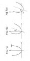
- FIG. 3 is a diagram illustrating the plotting, along the time axis, of the pitch variation of a sound signal outputted from the signal processing block 140.
- the sound signal outputted from the signal processing block 140 quickly lowers in its pitch in the vicinity of the closet approach time.
- the parameters are set so as to make the moving point correctly pass the closest approach position at the closest approach time, the synchronization between the above-mentioned sound image movement by the sound signal and the sound source movement represented by the moving picture will be lost.
- the above-mentioned parameter setting is visually executed, thereby making it difficult to correctly synchronize the above-mentioned sound image movement by the sound signal with the sound source movement represented by the moving picture.
- setting only the moving point trajectory and the closest approach time allows the computation of the closest approach position on the basis of the relationship between the trajectory and the fixed point, thereby adjusting the movement start position and the movement end position such that the moving point passes the closest approach position at the closest approach time. Consequently, the novel configuration realizes an advantage in which the above-mentioned sound image movement by the sound signal is easily and correctly synchronized with the sound source movement represented by the moving picture.
Landscapes
- Physics & Mathematics (AREA)
- Engineering & Computer Science (AREA)
- Acoustics & Sound (AREA)
- Signal Processing (AREA)
- Stereophonic System (AREA)
- Measurement Of Velocity Or Position Using Acoustic Or Ultrasonic Waves (AREA)
Abstract
Description
Meanwhile, if a sound source and a listener listening to a music sound generated from the sound source are moving relative to each other (for example, a sound source is moving at a predetermined velocity while the listener is standing still), the Doppler effect occurs in accordance with the relative movement. However, if a sound image movement is expressed solely by the time difference and the amplitude difference between the left and right signal lines as described above, the Doppler effect cannot be represented realistically, thereby causing a problem of poor sound quality.
In order to solve this problem, a technique was proposed as disclosed in Japanese Publication of Unexamined Patent Application No. Hei 06-327100, for example. In the disclosed technique, the frequency of a sound signal outputted from a frequency-variable sound source is varied in accordance with a manner by which a sound image moves, and the sound signal generated from the frequency-variable sound source and separated into the left and right channels is outputted as delayed in accordance with that movement, thereby rendering the Doppler effect.
In carrying out the invention and according to one aspect thereof, there is provided an apparatus for creating a sound image of an input sound signal in association with a moving point and a fixed point along a time axis, the sound image being associated with one of the moving point and the fixed point and the input sound signal being associated with the other of the moving point and the fixed point. The inventive apparatus comprises a setting section that sets input factors including a trajectory line which may be curved or straight and which represents a trajectory of the moving point, a nominal velocity of the moving point, a movement start time at which the moving point starts moving, a movement end time at which the moving point ends moving, and a closest approach time at which a distance between the moving point on the trajectory line and the fixed point is minimized, a position computation section that computes a closest approach position which is a position of the moving point on the trajectory line at the closest approach time, a movement start position which is a position of the moving point on the trajectory line at the movement start time, and a movement end position which is a position of the moving point on the trajectory line at the movement end time, on the basis of the input factors set by the setting section, a distance computation section that computes intermediate positions of the moving point along the trajectory line from the movement start position to the movement end position between the movement start time and the movement end time, and further computes a variable distance between each of the intermediate positions of the moving point and the fixed point, a velocity computation section that computes a variable velocity of the moving point relative to the fixed point along the time axis on the basis of the variable distance computed by the distance computation section, and a signal processing section that attenuates or delays the input sound signal in accordance with the variable distance computed by the distance computation section and that varies a pitch of the input sound signal on the basis of the variable velocity computed by the velocity computation section, thereby creating the sound image of the input sound signal along the time axis.
Preferably, the signal processing section computes a variation of the pitch of the input sound signal which is generated from one of the moving point and the fixed point and which is received by the other of the moving point and the fixed point, the apparatus further comprising a display section that displays the variation of the pitch of the input sound signal along the time axis.
Preferably, the setting section further sets an attenuation coefficient as one of the input factors, and the signal processing section determines an attenuation amount of the input sound signal in accordance with the variable distance, and further adjusts the attenuation amount in accordance with the attenuation coefficient.
As described and according to the invention, a sound image movement accompanying the Doppler effect in accordance with a relative movement between sound source and listener can be correctly and easily realized.
Referring to FIG. 1, there is shown a block diagram illustrating an exemplary configuration of a sound image
Claims (5)
- An apparatus for creating a sound image of an input sound signal in association with a moving point and a fixed point along a time axis, the sound image being associated with one of the moving point and the fixed point and the input sound signal being associated with the other of the moving point and the fixed point, the apparatus comprising:a setting section that sets input factors including a trajectory line which may be curved or straight and which represents a trajectory of the moving point, a nominal velocity of the moving point, a movement start time at which the moving point starts moving, a movement end time at which the moving point ends moving, and a closest approach time at which a distance between the moving point on the trajectory line and the fixed point is minimized;a position computation section that computes a closest approach position which is a position of the moving point on the trajectory line at the closest approach time, a movement start position which is a position of the moving point on the trajectory line at the movement start time, and a movement end position which is a position of the moving point on the trajectory line at the movement end time, on the basis of the input factors set by the setting section;a distance computation section that computes intermediate positions of the moving point along the trajectory line from the movement start position to the movement end position between the movement start time and the movement end time, and further computes a variable distance between each of the intermediate positions of the moving point and the fixed point;a velocity computation section that computes a variable velocity of the moving point relative to the fixed point along the time axis on the basis of the variable distance computed by the distance computation section; anda signal processing section that attenuates or delays the input sound signal in accordance with the variable distance computed by the distance computation section and that varies a pitch of the input sound signal on the basis of the variable velocity computed by the velocity computation section, thereby creating the sound image of the input sound signal along the time axis.
- The apparatus according to claim 1, wherein the signal processing section computes a variation of the pitch of the input sound signal which is generated from one of the moving point and the fixed point and which is received by the other of the moving point and the fixed point, the apparatus further comprising a display section that displays the variation of the pitch of the input sound signal along the time axis.
- The apparatus according to claim 1, wherein the setting section further sets an attenuation coefficient as one of the input factors, and the signal processing section determines an attenuation amount of the input sound signal in accordance with the variable distance, and further adjusts the attenuation amount in accordance with the attenuation coefficient.
- A program executable by a computer to perform a method of creating a sound image of an input sound signal in association with a moving point and a fixed point along a time axis, the sound image being associated with one of the moving point and the fixed point and the input sound signal being associated with the other of the moving point and the fixed point, wherein the method comprising the steps of:setting input factors including a trajectory line which may be curved or straight and which represents a trajectory of the moving point, a nominal velocity of the moving point, a movement start time at which the moving point starts moving, a movement end time at which the moving point ends moving, and a closest approach time at which a distance between the moving point on the trajectory line and the fixed point is minimized;computing a closest approach position which is a position of the moving point on the trajectory line at the closest approach time, a movement start position which is a position of the moving point on the trajectory line at the movement start time, and a movement end position which is a position of the moving point on the trajectory line at the movement end time, on the basis of the input factors;computing intermediate positions of the moving point along the trajectory line from the movement start position to the movement end position between the movement start time and the movement end time, and further computing a variable distance between each of the intermediate positions of the moving point and the fixed point;computing a variable velocity of the moving point relative to the fixed point along the time axis on the basis of the variable distance; andprocessing the input sound signal such as to attenuate or delay the input sound signal in accordance with the variable distance and to vary a pitch of the input sound signal on the basis of the variable velocity, thereby creating the sound image of the input sound signal along the time axis.
- A method of creating a sound image of an input sound signal in association with a moving point and a fixed point along a time axis, the sound image being associated with one of the moving point and the fixed point and the input sound signal being associated with the other of the moving point and the fixed point, the method comprising the steps of:setting input factors including a trajectory line which may be curved or straight and which represents a trajectory of the moving point, a nominal velocity of the moving point, a movement start time at which the moving point starts moving, a movement end time at which the moving point ends moving, and a closest approach time at which a distance between the moving point on the trajectory line and the fixed point is minimized;computing a closest approach position which is a position of the moving point on the trajectory line at the closest approach time, a movement start position which is a position of the moving point on the trajectory line at the movement start time, and a movement end position which is a position of the moving point on the trajectory line at the movement end time, on the basis of the input factors;computing intermediate positions of the moving point along the trajectory line from the movement start position to the movement end position between the movement start time and the movement end time, and further computing a variable distance between each of the intermediate positions of the moving point and the fixed point;computing a variable velocity of the moving point relative to the fixed point along the time axis on the basis of the variable distance; andprocessing the input sound signal such as to attenuate or delay the input sound signal in accordance with the variable distance and to vary a pitch of the input sound signal on the basis of the variable velocity, thereby creating the sound image of the input sound signal along the time axis.
Applications Claiming Priority (2)
| Application Number | Priority Date | Filing Date | Title |
|---|---|---|---|
| JP2004107458 | 2004-03-31 | ||
| JP2004107458A JP4541744B2 (en) | 2004-03-31 | 2004-03-31 | Sound image movement processing apparatus and program |
Publications (3)
| Publication Number | Publication Date |
|---|---|
| EP1585368A2 true EP1585368A2 (en) | 2005-10-12 |
| EP1585368A3 EP1585368A3 (en) | 2008-06-04 |
| EP1585368B1 EP1585368B1 (en) | 2009-09-09 |
Family
ID=34909456
Family Applications (1)
| Application Number | Title | Priority Date | Filing Date |
|---|---|---|---|
| EP05102389A Ceased EP1585368B1 (en) | 2004-03-31 | 2005-03-24 | Apparatus for creating sound image of moving sound source |
Country Status (4)
| Country | Link |
|---|---|
| US (1) | US7319760B2 (en) |
| EP (1) | EP1585368B1 (en) |
| JP (1) | JP4541744B2 (en) |
| DE (1) | DE602005016481D1 (en) |
Families Citing this family (16)
| Publication number | Priority date | Publication date | Assignee | Title |
|---|---|---|---|---|
| JP4914124B2 (en) * | 2006-06-14 | 2012-04-11 | パナソニック株式会社 | Sound image control apparatus and sound image control method |
| US7966147B2 (en) * | 2008-04-07 | 2011-06-21 | Raytheon Company | Generating images according to points of intersection for integer multiples of a sample-time distance |
| US8798385B2 (en) * | 2009-02-16 | 2014-08-05 | Raytheon Company | Suppressing interference in imaging systems |
| US10154361B2 (en) * | 2011-12-22 | 2018-12-11 | Nokia Technologies Oy | Spatial audio processing apparatus |
| WO2013184215A2 (en) * | 2012-03-22 | 2013-12-12 | The University Of North Carolina At Chapel Hill | Methods, systems, and computer readable media for simulating sound propagation in large scenes using equivalent sources |
| CN103052018B (en) * | 2012-12-19 | 2014-10-22 | 武汉大学 | Audio-visual distance information recovery method |
| CN103037301B (en) * | 2012-12-19 | 2014-11-05 | 武汉大学 | Convenient adjustment method for restoring range information of acoustic images |
| CN104134226B (en) * | 2014-03-12 | 2015-08-19 | 腾讯科技(深圳)有限公司 | Speech simulation method, device and client device in a kind of virtual scene |
| GB201409764D0 (en) | 2014-06-02 | 2014-07-16 | Accesso Technology Group Plc | Queuing system |
| US11900734B2 (en) | 2014-06-02 | 2024-02-13 | Accesso Technology Group Plc | Queuing system |
| JP5882403B2 (en) * | 2014-06-25 | 2016-03-09 | 株式会社カプコン | Sound effect processing program and game device |
| US10679407B2 (en) | 2014-06-27 | 2020-06-09 | The University Of North Carolina At Chapel Hill | Methods, systems, and computer readable media for modeling interactive diffuse reflections and higher-order diffraction in virtual environment scenes |
| US9977644B2 (en) | 2014-07-29 | 2018-05-22 | The University Of North Carolina At Chapel Hill | Methods, systems, and computer readable media for conducting interactive sound propagation and rendering for a plurality of sound sources in a virtual environment scene |
| US10248744B2 (en) | 2017-02-16 | 2019-04-02 | The University Of North Carolina At Chapel Hill | Methods, systems, and computer readable media for acoustic classification and optimization for multi-modal rendering of real-world scenes |
| WO2021186645A1 (en) * | 2020-03-18 | 2021-09-23 | 富士通株式会社 | Information processing program, device, and method |
| JP2025043120A (en) * | 2023-09-15 | 2025-03-28 | 株式会社東芝 | Acoustic signal processing device and method for processing an acoustic signal |
Family Cites Families (28)
| Publication number | Priority date | Publication date | Assignee | Title |
|---|---|---|---|---|
| US5440639A (en) * | 1992-10-14 | 1995-08-08 | Yamaha Corporation | Sound localization control apparatus |
| US5337363A (en) * | 1992-11-02 | 1994-08-09 | The 3Do Company | Method for generating three dimensional sound |
| JPH06233395A (en) * | 1993-01-13 | 1994-08-19 | Victor Co Of Japan Ltd | Video game authoring system |
| JPH06210069A (en) * | 1993-01-13 | 1994-08-02 | Victor Co Of Japan Ltd | Television game authoring system |
| GB9307934D0 (en) * | 1993-04-16 | 1993-06-02 | Solid State Logic Ltd | Mixing audio signals |
| JP3409364B2 (en) * | 1993-05-14 | 2003-05-26 | ヤマハ株式会社 | Sound image localization control device |
| US5717767A (en) * | 1993-11-08 | 1998-02-10 | Sony Corporation | Angle detection apparatus and audio reproduction apparatus using it |
| JPH07222299A (en) * | 1994-01-31 | 1995-08-18 | Matsushita Electric Ind Co Ltd | Sound image movement processing editing device |
| JP2937009B2 (en) * | 1994-03-30 | 1999-08-23 | ヤマハ株式会社 | Sound image localization control device |
| JP3258816B2 (en) * | 1994-05-19 | 2002-02-18 | シャープ株式会社 | 3D sound field space reproduction device |
| JPH08140199A (en) * | 1994-11-08 | 1996-05-31 | Roland Corp | Sound image localization setting device |
| JP3976360B2 (en) * | 1996-08-29 | 2007-09-19 | 富士通株式会社 | Stereo sound processor |
| JP3525653B2 (en) * | 1996-11-07 | 2004-05-10 | ヤマハ株式会社 | Sound adjustment device |
| JPH1188998A (en) * | 1997-09-02 | 1999-03-30 | Roland Corp | 3D sound image effect device |
| GB9805534D0 (en) * | 1998-03-17 | 1998-05-13 | Central Research Lab Ltd | A method of improving 3d sound reproduction |
| JPH11272156A (en) * | 1998-03-25 | 1999-10-08 | Sega Enterp Ltd | Virtual three-dimensional sound image generation apparatus and method and medium |
| JPH11331995A (en) * | 1998-05-08 | 1999-11-30 | Alpine Electronics Inc | Sound image controller |
| US6574339B1 (en) * | 1998-10-20 | 2003-06-03 | Samsung Electronics Co., Ltd. | Three-dimensional sound reproducing apparatus for multiple listeners and method thereof |
| JP3182754B2 (en) * | 1998-12-11 | 2001-07-03 | 日本電気株式会社 | Frequency analysis device and frequency analysis method |
| JP2000197198A (en) * | 1998-12-25 | 2000-07-14 | Matsushita Electric Ind Co Ltd | Sound image moving device |
| JP2000267675A (en) * | 1999-03-16 | 2000-09-29 | Sega Enterp Ltd | Sound signal processing device |
| US6683959B1 (en) * | 1999-09-16 | 2004-01-27 | Kawai Musical Instruments Mfg. Co., Ltd. | Stereophonic device and stereophonic method |
| GB2376585B (en) * | 2001-06-12 | 2005-03-23 | Roke Manor Research | System for determining the position and/or speed of a moving object |
| WO2004071280A2 (en) * | 2003-02-07 | 2004-08-26 | Michael Sasha John | Rapid screening, threshold, and diagnostic tests for evaluation of hearing |
| JP2003330536A (en) * | 2002-05-09 | 2003-11-21 | Mitsubishi Heavy Ind Ltd | Moving body course planning |
| JP2003348700A (en) * | 2002-05-28 | 2003-12-05 | Victor Co Of Japan Ltd | Presence signal generating method, and presence signal generating apparatus |
| JP2004007211A (en) * | 2002-05-31 | 2004-01-08 | Victor Co Of Japan Ltd | Transmitting-receiving system for realistic sensations signal, signal transmitting apparatus, signal receiving apparatus, and program for receiving realistic sensations signal |
| EP1370115B1 (en) * | 2002-06-07 | 2009-07-15 | Panasonic Corporation | Sound image control system |
-
2004
- 2004-03-31 JP JP2004107458A patent/JP4541744B2/en not_active Expired - Fee Related
-
2005
- 2005-03-24 DE DE602005016481T patent/DE602005016481D1/en not_active Expired - Lifetime
- 2005-03-24 EP EP05102389A patent/EP1585368B1/en not_active Ceased
- 2005-03-29 US US11/093,653 patent/US7319760B2/en not_active Expired - Fee Related
Also Published As
| Publication number | Publication date |
|---|---|
| EP1585368A3 (en) | 2008-06-04 |
| JP2005295207A (en) | 2005-10-20 |
| US7319760B2 (en) | 2008-01-15 |
| EP1585368B1 (en) | 2009-09-09 |
| US20050220308A1 (en) | 2005-10-06 |
| JP4541744B2 (en) | 2010-09-08 |
| DE602005016481D1 (en) | 2009-10-22 |
Similar Documents
| Publication | Publication Date | Title |
|---|---|---|
| EP1585368B1 (en) | Apparatus for creating sound image of moving sound source | |
| Wenzel | Localization in virtual acoustic displays | |
| US6898291B2 (en) | Method and apparatus for using visual images to mix sound | |
| EP2891955B1 (en) | In-vehicle gesture interactive spatial audio system | |
| US5636283A (en) | Processing audio signals | |
| US20110109798A1 (en) | Method and system for simultaneous rendering of multiple multi-media presentations | |
| US8331575B2 (en) | Data processing apparatus and parameter generating apparatus applied to surround system | |
| US10643592B1 (en) | Virtual / augmented reality display and control of digital audio workstation parameters | |
| JP2003244800A (en) | Sound image localization device | |
| US20060159276A1 (en) | Audio system | |
| US5682433A (en) | Audio signal processor for simulating the notional sound source | |
| JPH10248098A (en) | Sound processing device | |
| JP7604785B2 (en) | SOUND PROCESSING METHOD AND SOUND PROCESSING APPARATUS | |
| EP1819198B1 (en) | Method for synthesizing impulse response and method for creating reverberation | |
| WO2025025844A1 (en) | Control method and media output device | |
| US20130089221A1 (en) | Sound reproducing apparatus | |
| JP2022037104A (en) | Operation device, control method of the same, and program | |
| KR970000396B1 (en) | A device and a method for compensating sound magnificancy in audio & video devices | |
| JP2001136600A (en) | Display device | |
| US20250126432A1 (en) | Spectrogram Localization Algorithm | |
| JP3059882B2 (en) | Perspective control device for sound | |
| JP3613110B2 (en) | Automatic sound source adjustment circuit | |
| KR19990051125A (en) | Acoustic phase controller using head transfer function | |
| CN121807257A (en) | Audio processing method, device, equipment, system, vehicle, medium and product | |
| JPH11355900A (en) | Surround localizing point control system |
Legal Events
| Date | Code | Title | Description |
|---|---|---|---|
| PUAI | Public reference made under article 153(3) epc to a published international application that has entered the european phase |
Free format text: ORIGINAL CODE: 0009012 |
|
| 17P | Request for examination filed |
Effective date: 20050325 |
|
| AK | Designated contracting states |
Kind code of ref document: A2 Designated state(s): AT BE BG CH CY CZ DE DK EE ES FI FR GB GR HU IE IS IT LI LT LU MC NL PL PT RO SE SI SK TR |
|
| AX | Request for extension of the european patent |
Extension state: AL BA HR LV MK YU |
|
| RAP1 | Party data changed (applicant data changed or rights of an application transferred) |
Owner name: YAMAHA CORPORATION |
|
| PUAL | Search report despatched |
Free format text: ORIGINAL CODE: 0009013 |
|
| AK | Designated contracting states |
Kind code of ref document: A3 Designated state(s): AT BE BG CH CY CZ DE DK EE ES FI FR GB GR HU IE IS IT LI LT LU MC NL PL PT RO SE SI SK TR |
|
| AX | Request for extension of the european patent |
Extension state: AL BA HR LV MK YU |
|
| AKX | Designation fees paid |
Designated state(s): DE GB |
|
| GRAP | Despatch of communication of intention to grant a patent |
Free format text: ORIGINAL CODE: EPIDOSNIGR1 |
|
| GRAS | Grant fee paid |
Free format text: ORIGINAL CODE: EPIDOSNIGR3 |
|
| GRAA | (expected) grant |
Free format text: ORIGINAL CODE: 0009210 |
|
| AK | Designated contracting states |
Kind code of ref document: B1 Designated state(s): DE GB |
|
| REG | Reference to a national code |
Ref country code: GB Ref legal event code: FG4D |
|
| REF | Corresponds to: |
Ref document number: 602005016481 Country of ref document: DE Date of ref document: 20091022 Kind code of ref document: P |
|
| PLBE | No opposition filed within time limit |
Free format text: ORIGINAL CODE: 0009261 |
|
| STAA | Information on the status of an ep patent application or granted ep patent |
Free format text: STATUS: NO OPPOSITION FILED WITHIN TIME LIMIT |
|
| 26N | No opposition filed |
Effective date: 20100610 |
|
| PGFP | Annual fee paid to national office [announced via postgrant information from national office to epo] |
Ref country code: GB Payment date: 20140319 Year of fee payment: 10 |
|
| PGFP | Annual fee paid to national office [announced via postgrant information from national office to epo] |
Ref country code: DE Payment date: 20140417 Year of fee payment: 10 |
|
| REG | Reference to a national code |
Ref country code: DE Ref legal event code: R119 Ref document number: 602005016481 Country of ref document: DE |
|
| GBPC | Gb: european patent ceased through non-payment of renewal fee |
Effective date: 20150324 |
|
| PG25 | Lapsed in a contracting state [announced via postgrant information from national office to epo] |
Ref country code: DE Free format text: LAPSE BECAUSE OF NON-PAYMENT OF DUE FEES Effective date: 20151001 Ref country code: GB Free format text: LAPSE BECAUSE OF NON-PAYMENT OF DUE FEES Effective date: 20150324 |