EP1585290A2 - Battery pack locking apparatus for mobile communication terminals - Google Patents
Battery pack locking apparatus for mobile communication terminals Download PDFInfo
- Publication number
- EP1585290A2 EP1585290A2 EP05002978A EP05002978A EP1585290A2 EP 1585290 A2 EP1585290 A2 EP 1585290A2 EP 05002978 A EP05002978 A EP 05002978A EP 05002978 A EP05002978 A EP 05002978A EP 1585290 A2 EP1585290 A2 EP 1585290A2
- Authority
- EP
- European Patent Office
- Prior art keywords
- battery pack
- locker unit
- terminal body
- slide
- push
- Prior art date
- Legal status (The legal status is an assumption and is not a legal conclusion. Google has not performed a legal analysis and makes no representation as to the accuracy of the status listed.)
- Withdrawn
Links
Images


Classifications
-
- H—ELECTRICITY
- H04—ELECTRIC COMMUNICATION TECHNIQUE
- H04B—TRANSMISSION
- H04B1/00—Details of transmission systems, not covered by a single one of groups H04B3/00 - H04B13/00; Details of transmission systems not characterised by the medium used for transmission
- H04B1/38—Transceivers, i.e. devices in which transmitter and receiver form a structural unit and in which at least one part is used for functions of transmitting and receiving
- H04B1/3827—Portable transceivers
- H04B1/3883—Arrangements for mounting batteries or battery chargers
-
- H—ELECTRICITY
- H04—ELECTRIC COMMUNICATION TECHNIQUE
- H04B—TRANSMISSION
- H04B1/00—Details of transmission systems, not covered by a single one of groups H04B3/00 - H04B13/00; Details of transmission systems not characterised by the medium used for transmission
- H04B1/38—Transceivers, i.e. devices in which transmitter and receiver form a structural unit and in which at least one part is used for functions of transmitting and receiving
- H04B1/40—Circuits
-
- H—ELECTRICITY
- H04—ELECTRIC COMMUNICATION TECHNIQUE
- H04M—TELEPHONIC COMMUNICATION
- H04M1/00—Substation equipment, e.g. for use by subscribers
- H04M1/02—Constructional features of telephone sets
- H04M1/0202—Portable telephone sets, e.g. cordless phones, mobile phones or bar type handsets
- H04M1/026—Details of the structure or mounting of specific components
- H04M1/0262—Details of the structure or mounting of specific components for a battery compartment
-
- Y—GENERAL TAGGING OF NEW TECHNOLOGICAL DEVELOPMENTS; GENERAL TAGGING OF CROSS-SECTIONAL TECHNOLOGIES SPANNING OVER SEVERAL SECTIONS OF THE IPC; TECHNICAL SUBJECTS COVERED BY FORMER USPC CROSS-REFERENCE ART COLLECTIONS [XRACs] AND DIGESTS
- Y02—TECHNOLOGIES OR APPLICATIONS FOR MITIGATION OR ADAPTATION AGAINST CLIMATE CHANGE
- Y02E—REDUCTION OF GREENHOUSE GAS [GHG] EMISSIONS, RELATED TO ENERGY GENERATION, TRANSMISSION OR DISTRIBUTION
- Y02E60/00—Enabling technologies; Technologies with a potential or indirect contribution to GHG emissions mitigation
- Y02E60/10—Energy storage using batteries
Definitions
- the present invention relates to a battery pack locking apparatus for mobile communication terminals, and more particularly to an apparatus that is capable of detachably locking a battery pack to a terminal body of a mobile communication terminal.
- a battery pack 10 which serves to supply electric power to a mobile communication terminal, is detachably locked to the rear part of a terminal body 1 of the mobile communication terminal, as shown in FIG. 1.
- the battery pack 10 is locked to or detached from the terminal body 1 by means of a battery pack locking apparatus 20 mounted to the terminal body 1.
- the battery pack 10 may be locked to the rear part of the terminal body 1 through the use of a slide-type locking mechanism for slidably locking pack 10 to the rear part of the terminal body 1 by means of guide ribs and a latching member, so that the battery pack 10 is pushed toward the terminal body 1 until the battery pack 10 is completely locked to the terminal body 1.
- the battery pack 10 is typically provided at front and rear parts of the lower end thereof with electric contacts (not shown) such that at leat one pair of the electric contacts are exposed.
- the electric contacts provided on the front surface of the battery pack 10 contact electric contacts (not shown) formed on an electric charger when the battery pack 10 is to be charged while the electric contacts provided at the rear part of the battery pack 10 contact electric contacts (not shown) formed on the rear surface of the terminal body 1.
- the battery pack 10 is detachably locked to the rear part of the terminal body 1 by means of the conventional battery pack locking apparatus 20 mounted to the terminal body 1, specifically to a rear casing frame 1 a of the terminal body 1.
- the terminal body 1 is provided with a battery pack space 1 b formed at the rear casing frame 1 a. At one end of the battery pack space 1b is formed electric contacts (not shown). At a prescribed position of the rear casing frame 1 a adjacent to the other end of the battery pack locking space 1 b is formed a mounting groove 1 c, in which the battery pack apparatus 10 is mounted for locking the battery pack 10 to the terminal body 1.
- the battery pack 10 constructed as described above is to be locked to the terminal body 1
- the battery pack 10 is fitted into the battery pack space 1 b of the terminal body 1.
- lockers 21 of the battery pack locking apparatus 20 are engaged into an engaging groove 11 formed at the battery pack 10 (See FIG. 2). Consequently, the battery pack 10 is securely locked to the terminal body 1 by means of the lockers 21.
- the lockers 21 are pulled toward the upper end of the terminal body 1, by sliding the lockers away from the battery pack. As a result, the lockers 21 are disengaged from the engaging groove 11 of the battery pack 10, and therefore the battery pack 10 may be detached from the terminal body 1.
- the mounting groove 1 c has a sufficient space defined therein so that the lockers 21 can be slid toward the upper and lower ends of the terminal body 1.
- FIG. 2 is a cross-sectional view showing the construction of the conventional battery pack locking apparatus for mobile communication terminals shown in FIG. 1.
- the conventional battery pack locking apparatus 20 includes two guide ribs 23, which are mounted to the rear casing frame 1 a to guide the guide ribs 23 toward the front and the rear of the terminal body 1.
- each guide rib 23 At one end of each guide rib 23 is formed a hooking member 23a, which is by means of a corresponding catching protrusion 2 formed on the rear casing frame 1 a. Consequently, separation of the lockers 21 from the engaging groove 11 of the battery pack 10 is effectively prevented during a sliding movement of the lockers 21 toward the upper/lower end of the terminal body 1 once the lockers 21 are engaged into the engaging groove 11.
- the battery pack locking apparatus 20 further includes an elastic member, such as a spring 30, for providing a prescribed elastic force to the lockers 21. The spring 30 presses against the lockers while being supported by means of the rear casing frame 1 a.
- the conventional battery pack locking apparatus for mobile communication terminals it is necessary that a sufficient space be provided in the mounting groove, in which the lockers can be slid toward the upper and lower ends of the terminal body.
- the size of the terminal body of the mobile communication terminal is increased, and the external appearance of the mobile communication terminal is poor.
- the structure of the battery pack locking apparatus is very complicated, which deteriorates productivity and reliability of the battery pack locking apparatus.
- the space groove must also be kept clear of debris.
- the lockers be pulled toward the upper end of the terminal body while the lockers are pressed by means of a fingernail of a user when the battery pack is to be detached from the terminal body. As a result, the fingernail of the user may be injured.
- a battery pack locking apparatus for locking a battery pack to a battery pack space formed at a rear casing frame of a terminal body of a mobile communication terminal
- the battery pack locking apparatus includes a mounting groove formed on the rear casing frame; a push locker unit mounted in the mounting groove such that the push locker unit can be moved toward the front and the rear of the terminal body when the push locker unit is pushed; a slide locker unit coupled with the push locker unit at the lower part of the push locker unit such that the slide locker unit can be slid toward the upper and lower ends of the terminal body, as the push locker unit is moved toward the front and the rear of the terminal body, for locking the battery pack to the battery pack space or popping the battery pack out of the battery pack space when the battery pack is unlocked from the battery pack space; and a coil spring mounted to the slide locker unit for providing an elastic force so that the push locker unit is moved toward the front and the rear of the terminal body and the slide locker unit is slid toward the
- a battery pack locking apparatus 100 for mobile communication terminal comprises a mounting groove 200, a push locker unit 300, a slide locker unit 400, and a coil spring 500.
- the mounting groove 200 is formed at a prescribed position of a rear casing frame 1 a of a terminal body 1 such that the push locker unit 300 is mounted in the mounting groove 200.
- the push locker unit 300 is mounted in the mounting groove 200 such that the push locker unit 300 can be moved toward the front and the rear of the terminal body 1 when the push locker unit 300 is pushed.
- the slide locker unit 400 is coupled with the push locker unit 300 at the lower part of the push locker unit 300 such that the slide locker unit 400 can be slid toward the upper and lower ends of the terminal body 1, as the push locker unit 300 is moved toward the front and the rear of the terminal body 1, for locking the battery pack 10 to the battery pack space 1 b formed at the rear casing frame 1 a of the terminal body 1 or unlocking the battery pack 10 from the battery pack space 1b and then popping the battery pack 10 out of the battery pack space 1 b immediately when the battery pack 10 is unlocked from the battery pack space 1 b.
- the coil spring 500 is mounted to the slide locker unit 400 for providing an elastic force, by which the push locker unit 300 is moved toward the front and the rear of the terminal body 1 and the slide locker unit 400 is slid toward the upper and lower ends of the terminal body 1.
- the mounting groove 200 is provided at both sides thereof with two latch holes 201, respectively, through which hook members 302 formed on the push locker unit 300 are inserted, respectively, such that the hook members 302 are retained within the corresponding latch holes 201.
- the mounting groove 200 is provided at a middle part thereof with a through-hole 202, through which a guide protrusion 303 formed on the push locker unit 300 is inserted.
- the upper end of the bottom of the mounting groove 200 is provided a supporting plate 203, which extends toward the front of the terminal body 1 for movably supporting a spring protrusion 402 formed on the slide locker unit 400.
- a plate-side through-hole 203a On the supporting plate 203 is formed a plate-side through-hole 203a, through which the spring protrusion 402 is inserted such that the slide locker unit 400 can be slid toward the upper and lower ends of the terminal body 1.
- Adjacent to the mounting groove 200 are formed two separation-preventing protrusions 204, which are securely engaged with latch protrusions 404 formed on the slide locker unit 400, respectively, for preventing separation of the slide locker unit 400 from the mounting groove 200, as best seen in FIG. 7.
- the push locker unit 300 comprises a locker button 301, two hooking members 302, and guide protrusion 303.
- the locker button 301 is mounted in the mounting groove 200 while being exposed such that an external force can be applied to the locker button 301.
- the hook members 302 are formed at both sides of the bottom of the locker button 301 while extending from the locker button 301 such that the hook members 302 can be inserted through the latch holes 201 of the mounting groove 200, respectively, and then the hook members 302 can be retained within the corresponding latch holes 201.
- the guide protrusion 303 is formed between the hook members 302 such that the guide protrusion 303 is inserted though the through-hole 202 formed through the middle part of the mounting groove 200, and is guided along a hole-side inclined surface 403a formed on the slide locker unit 400.
- a protrusion-side inclined surface 303a such that the guide protrusion 303 can be guided while the protrusion-side inclined surface 303a is in contact with the hole-side inclined surface 403a of the slide locker unit 400.
- a guide hole 403 is formed at the middle part of the slide locker unit 400 such that the guide protrusion 303 is inserted.
- the hole-side inclined surface 403a is formed at the guide hole 403 such that the hole-side inclined surface 403a corresponds to the protrusion-side inclined surface 303a.
- the slide locker unit 400 is provided at one end thereof with a hook 401, which is engaged into or disengaged from an engaging groove 11 formed on the battery pack 10 as the slide locking unit 400 is slid toward the upper and lower ends of the terminal body 1, as seen in FIG. 8.
- the slide locker unit 400 is provided at the other end thereof with a spring protrusion 402 extending in the longitudinal direction of the slide locker unit 400, on which the coil spring 500 is fitted.
- the hook 401 has a guide surface 401 a formed at one end thereof, along which the hook 401 is guided when the hook is engaged into or disengaged from the engaging groove 11 of the battery pack 10.
- the guide surface 401 a of the hook 401 is inclined to facilitate sliding the hook 401 into the engaging groove 11 of the battery pack 10 or to facilitate sliding the hook 401 from the groove 11 to enable the battery pack to be popped from the battery pack space 1 b.
- a frame-side through-hole 600 through which the hook 401 is inserted toward the inside of the battery pack space 1 b such that the hook can be engaged into the engaging groove 11 of the battery pack 10.
- the battery pack locking apparatus 100 for mobile communication terminals includes the mounting groove 200, the push locker unit 300, the slide locker unit 400, and the coil spring 500.
- the mounting groove 200 is formed at a prescribed position of the rear casing frame 1 a of the terminal body 1, and the push locker unit 300 is mounted in the mounting groove 200 such that the push locker unit 300 can be moved toward the front and the rear of the terminal body 1 when the push locker unit 300 is pushed.
- the slide locker unit 400 is coupled with the push locker unit 300 at the lower part of the push locker unit 300 such that the slide locker unit 400 can be slid toward the upper and lower ends of the terminal body 1 as the push locker unit 300 is moved toward the front and the rear of the terminal body 1 for popping the battery pack 10 out of the battery pack space 1b when the battery pack 10 is unlocked from the battery pack space 1 b.
- the hook members 302 are formed at both sides of the bottom of the locker button 301 while extending from the locker button 301 such that the hook members 302 are inserted through the latch holes 201 of the mounting groove 200, respectively, and then the hooking members 302 are retained within the corresponding latch holes 201.
- the hook 401 is formed at one end of the slide locker unit 400 such that the hook 401 can be engaged into or disengaged from the engaging groove 11 of the battery pack 10 as the slide locking unit 400 is slid toward the upper and lower ends of the terminal body 1. As shown in FIG. 6, the hook 401 is inserted through the frame-side through-hole 600 formed at the rear casing frame 1 a of the terminal body 1.
- the spring protrusion 402 is formed at the other end of the slide locker unit 400 in the longitudinal direction of the slide locker unit 400 such that the coil spring 500 is fitted on the spring protrusion 402.
- the latch protrusions 404 are formed at both sides of the slide locker unit 400 so that separation of the slide locker unit 400 from the mounting groove 200 is prevented when the slide locker unit 400 is slid toward the upper and lower ends of the terminal body 1, as shown in FIG. 7. Consequently, the latch protrusions 404 are engaged with the separation-preventing protrusions 204 formed adjacent to the mounting groove 200 so that separation of the slide locker unit 400 from the mounting groove 200 is prevented.
- the guide protrusion 303 formed at the middle part of the push locker unit 300 is inserted through the through-hole 202 formed at the middle part of the mounting groove 200. Also, the guide protrusion 303 is inserted through the guide hole 403 formed on the slide locker unit 400.
- the protrusion-side inclined surface 303a is formed on the guide protrusion 303, which corresponds to the hole-side inclined surface 403a formed at the guide hole 403, as shown in FIG. 4.
- the locker button 301 of the push locker unit 300 mounted in the mounting groove 200 is pushed by a user in the direction of Arrow Y so that the push locker unit 300 is moved toward the front of the terminal body 1.
- the slide locker unit 400 slides in the direction of Arrow X, along the longitudinal axis of the terminal body 1, toward the upper end of the terminal body 1 by means of the guide protrusion 303 of the push locker unit 300 inserted in the guide hole 403 of the slide locker unit 400, as shown in FIGS. 9 and 10.
- the protrusion-side inclined surface 303a of the guide protrusion 303 is in contact with the hole-side inclined surface 403a of the guide hole 403, as shown in FIG. 10, the protrusion-side inclined surface 303a is guided along the hole-side inclined surface 403a in the direction of Arrow Z as the guide protrusion 303 is moved toward the front of the terminal body 1. Consequently, the slide locker unit 400 is slid toward the upper end of the terminal body 1 in the direction of Arrow X.
- the hook 401 of the slide locker unit 400 also slides so that the hook 401 is disengaged from the engaging groove 11 of the battery pack 10.
- the slide locker unit 400 When the external force applied to the push button 301 of the push locker unit 300 is removed, the slide locker unit 400 is slid toward the lower end of the terminal body 1 by means of the elastic force of the coil spring 500 provided at the slide locker unit 400 in a direction opposite to Arrow X.
- the hook 401 At one end of the hook 401 is formed the guide surface 401 a, along which the battery pack 10 is guided so that the battery pack 10 is popped out of the battery pack space 1 b toward the rear of the terminal body 1 when the hook 401 is disengaged from the engaging groove 11 of the battery pack 10. Consequently, the hook 401 is moved into the frame-side through-hole 600 when the hook 401 is disengaged from the engaging groove 11 of the battery pack 10, as shown in FIGS. 10 and 11, and then the hook 401 is extended outwardly from the frame-side through-hole 600 by means of the elastic force of the coil spring 500. As a result, the battery pack 10 is pushed toward the rear of the terminal body 1 along the guide surface 401 a of the hook 401 so that the battery pack 10 is popped out of the battery pack space 1 b of the terminal body 1.
- the battery pack 10 is raised from the battery pack space 1b of the rear casing frame 1 a to a prescribed height. Consequently, the raised battery pack 10 can be easily separated from the rear casing frame 1 a of the terminal body 1.
- the battery pack 10 When the battery pack 10 is to be locked in the battery pack space 1b, as shown in FIGS. 9 and 10, the battery pack 10 is guided along the guide surface of the hook 401, and the hook 401 is engaged into the engaging groove 11 so that the battery pack 10 is securely locked to the rear casing frame 1 a of the terminal body 1.
- the hook 401 is forced into the frame-side through-hole 600, and is then extended from the frame-side through-hole 600 by means of the elastic force of the coil spring 500 so that the hook 401 is engaged into the engaging groove 11 of the battery pack 10.
- the protrusion-side inclined surface 303a is guided so that the push locker unit 300 is moved toward the rear of the terminal body 1.
- the present invention provides a battery pack locking apparatus for mobile communication terminals that is capable of securely locking a battery pack to a terminal body of a mobile communication terminal when the battery pack is attached to the terminal body of the mobile communication terminal and easily detaching the battery pack from the terminal body once the battery pack locking apparatus is simply pushed, whereby the battery pack is easily attached to or detached from the terminal body of the mobile communication terminal.
Landscapes
- Engineering & Computer Science (AREA)
- Signal Processing (AREA)
- Computer Networks & Wireless Communication (AREA)
- Battery Mounting, Suspending (AREA)
- Telephone Set Structure (AREA)
Abstract
Description
- The present invention relates to a battery pack locking apparatus for mobile communication terminals, and more particularly to an apparatus that is capable of detachably locking a battery pack to a terminal body of a mobile communication terminal.
- Generally, a
battery pack 10, which serves to supply electric power to a mobile communication terminal, is detachably locked to the rear part of aterminal body 1 of the mobile communication terminal, as shown in FIG. 1. Thebattery pack 10 is locked to or detached from theterminal body 1 by means of a batterypack locking apparatus 20 mounted to theterminal body 1. - The
battery pack 10 may be locked to the rear part of theterminal body 1 through the use of a slide-type locking mechanism for slidablylocking pack 10 to the rear part of theterminal body 1 by means of guide ribs and a latching member, so that thebattery pack 10 is pushed toward theterminal body 1 until thebattery pack 10 is completely locked to theterminal body 1. - The
battery pack 10 is typically provided at front and rear parts of the lower end thereof with electric contacts (not shown) such that at leat one pair of the electric contacts are exposed. The electric contacts provided on the front surface of thebattery pack 10 contact electric contacts (not shown) formed on an electric charger when thebattery pack 10 is to be charged while the electric contacts provided at the rear part of thebattery pack 10 contact electric contacts (not shown) formed on the rear surface of theterminal body 1. - As shown in FIG. 1, the
battery pack 10 is detachably locked to the rear part of theterminal body 1 by means of the conventional batterypack locking apparatus 20 mounted to theterminal body 1, specifically to arear casing frame 1 a of theterminal body 1. - The
terminal body 1 is provided with abattery pack space 1 b formed at therear casing frame 1 a. At one end of thebattery pack space 1b is formed electric contacts (not shown). At a prescribed position of therear casing frame 1 a adjacent to the other end of the batterypack locking space 1 b is formed amounting groove 1 c, in which thebattery pack apparatus 10 is mounted for locking thebattery pack 10 to theterminal body 1. - When the
battery pack 10 constructed as described above is to be locked to theterminal body 1, thebattery pack 10 is fitted into thebattery pack space 1 b of theterminal body 1. At this time,lockers 21 of the batterypack locking apparatus 20 are engaged into anengaging groove 11 formed at the battery pack 10 (See FIG. 2). Consequently, thebattery pack 10 is securely locked to theterminal body 1 by means of thelockers 21. - When the
battery pack 10 is to be detached from theterminal body 1, thelockers 21 are pulled toward the upper end of theterminal body 1, by sliding the lockers away from the battery pack. As a result, thelockers 21 are disengaged from theengaging groove 11 of thebattery pack 10, and therefore thebattery pack 10 may be detached from theterminal body 1. - The
mounting groove 1 c has a sufficient space defined therein so that thelockers 21 can be slid toward the upper and lower ends of theterminal body 1. - FIG. 2 is a cross-sectional view showing the construction of the conventional battery pack locking apparatus for mobile communication terminals shown in FIG. 1. As shown in FIG. 2, the conventional battery
pack locking apparatus 20 includes twoguide ribs 23, which are mounted to therear casing frame 1 a to guide theguide ribs 23 toward the front and the rear of theterminal body 1. - At one end of each
guide rib 23 is formed a hookingmember 23a, which is by means of a corresponding catchingprotrusion 2 formed on therear casing frame 1 a. Consequently, separation of thelockers 21 from theengaging groove 11 of thebattery pack 10 is effectively prevented during a sliding movement of thelockers 21 toward the upper/lower end of theterminal body 1 once thelockers 21 are engaged into theengaging groove 11. The batterypack locking apparatus 20 further includes an elastic member, such as aspring 30, for providing a prescribed elastic force to thelockers 21. Thespring 30 presses against the lockers while being supported by means of therear casing frame 1 a. - With the conventional battery pack locking apparatus for mobile communication terminals, however, it is necessary that a sufficient space be provided in the mounting groove, in which the lockers can be slid toward the upper and lower ends of the terminal body. As a result, the size of the terminal body of the mobile communication terminal is increased, and the external appearance of the mobile communication terminal is poor. As a further result, the structure of the battery pack locking apparatus is very complicated, which deteriorates productivity and reliability of the battery pack locking apparatus. The space groove must also be kept clear of debris.
- Also, it is necessary that the lockers be pulled toward the upper end of the terminal body while the lockers are pressed by means of a fingernail of a user when the battery pack is to be detached from the terminal body. As a result, the fingernail of the user may be injured.
- Therefore, the present invention has been made in view of the above problems.
- It is the object of the present invention to provide a battery pack locking apparatus for mobile communication terminals that is capable of securely locking a battery pack to a terminal body of a mobile communication terminal and easily detaching the battery pack from the terminal body once the battery pack locking apparatus is simply pushed.
- This object is solved by the subject matter of the independent claims.
- Preferred embodiments are defined in the dependent claims.
- It is an aspect of the present invention to provide a battery pack locking apparatus for mobile communication terminals that is capable of securely locking a battery pack to a terminal body of a mobile communication terminal and easily detaching the battery pack from the terminal body once the battery pack locking apparatus is simply pushed, whereby the structure of the mobile communication terminal is simplified, productivity and reliability of the mobile communication terminal are guaranteed, and the mobile communication terminal has an aesthetically pleasing external appearance.
- In accordance with the present invention, the above and other aspects can be accomplished by the provision of a battery pack locking apparatus for locking a battery pack to a battery pack space formed at a rear casing frame of a terminal body of a mobile communication terminal, wherein the battery pack locking apparatus includes a mounting groove formed on the rear casing frame; a push locker unit mounted in the mounting groove such that the push locker unit can be moved toward the front and the rear of the terminal body when the push locker unit is pushed; a slide locker unit coupled with the push locker unit at the lower part of the push locker unit such that the slide locker unit can be slid toward the upper and lower ends of the terminal body, as the push locker unit is moved toward the front and the rear of the terminal body, for locking the battery pack to the battery pack space or popping the battery pack out of the battery pack space when the battery pack is unlocked from the battery pack space; and a coil spring mounted to the slide locker unit for providing an elastic force so that the push locker unit is moved toward the front and the rear of the terminal body and the slide locker unit is slid toward the upper and lower ends of the terminal body.
- The above features and other advantages of the present invention will be more clearly understood from the following detailed description taken in conjunction with the accompanying drawings, in which:
- FIG. 1 is a perspective view showing a conventional battery pack locking apparatus for mobile communication terminals;
- FIG. 2 is a plan view, in section, showing the construction of the conventional battery pack locking apparatus for mobile communication terminals shown in FIG. 1;
- FIG. 3 is an exploded perspective view showing the construction of a battery pack locking apparatus for mobile communication terminals according to a preferred embodiment of the present invention;
- FIG. 4 is a perspective view showing a push locker unit and a slide locker unit of the battery pack locking apparatus according to the preferred embodiment of the present invention shown in FIG. 3;
- FIG. 5 is a perspective view showing the battery pack locking apparatus according to the preferred embodiment of the present invention shown in FIG. 3 mounted to a terminal body of a mobile communication terminal;
- FIG. 6 is a side cross-sectional view taken along lines 6-6 of FIG. 5 of the battery pack locking apparatus mounted to the terminal body of the mobile communication terminal shown in FIG. 5;
- FIG. 7 is a plan view in partial cut-away showing the rear part of the battery pack locking apparatus according to the preferred embodiment of the present invention shown in FIG. 3;
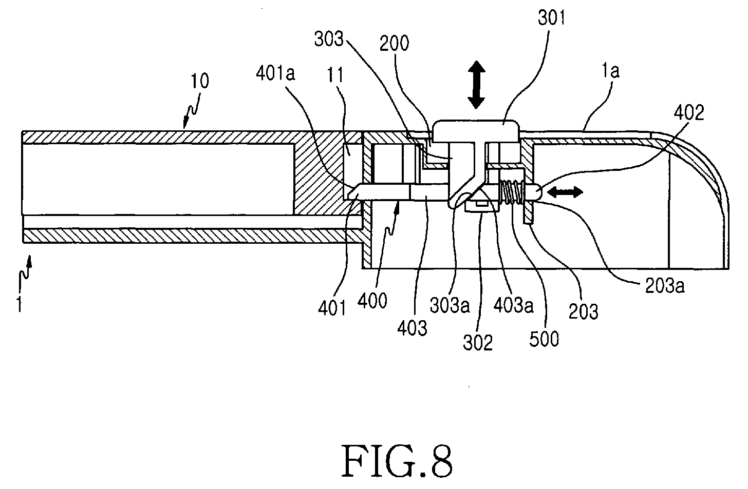
- FIG. 8 is a side cross-sectional view of the battery pack locking apparatus according to the preferred embodiment of the present invention shown in FIG. 3 before the battery pack locking apparatus is being operated;
- FIG. 9 is a side cross-sectional view of the battery pack locking apparatus according to the preferred embodiment of the present invention shown in FIG. 3 while the battery pack locking apparatus is operated;
- FIG. 10 is an enlarged side cross-sectional view of part A shown in FIG. 9; and
- FIG. 11 is a side cross-sectional view of the battery pack locking apparatus according to the preferred embodiment of the present invention shown in FIG. 3 after the battery pack locking apparatus has been operated.
-
- Now, a preferred embodiment of the present invention will be described in detail with reference to the annexed drawings. In the drawings, the same or similar elements are denoted by the same reference numerals even though they are depicted in different drawings.
- As shown in FIGS. 3 to 11, a battery
pack locking apparatus 100 for mobile communication terminal comprises amounting groove 200, apush locker unit 300, aslide locker unit 400, and acoil spring 500. - The
mounting groove 200 is formed at a prescribed position of arear casing frame 1 a of aterminal body 1 such that thepush locker unit 300 is mounted in themounting groove 200. Thepush locker unit 300 is mounted in themounting groove 200 such that thepush locker unit 300 can be moved toward the front and the rear of theterminal body 1 when thepush locker unit 300 is pushed. - The
slide locker unit 400 is coupled with thepush locker unit 300 at the lower part of thepush locker unit 300 such that theslide locker unit 400 can be slid toward the upper and lower ends of theterminal body 1, as thepush locker unit 300 is moved toward the front and the rear of theterminal body 1, for locking thebattery pack 10 to thebattery pack space 1 b formed at therear casing frame 1 a of theterminal body 1 or unlocking thebattery pack 10 from thebattery pack space 1b and then popping thebattery pack 10 out of thebattery pack space 1 b immediately when thebattery pack 10 is unlocked from thebattery pack space 1 b. - The
coil spring 500 is mounted to theslide locker unit 400 for providing an elastic force, by which thepush locker unit 300 is moved toward the front and the rear of theterminal body 1 and theslide locker unit 400 is slid toward the upper and lower ends of theterminal body 1. - The
mounting groove 200 is provided at both sides thereof with twolatch holes 201, respectively, through whichhook members 302 formed on thepush locker unit 300 are inserted, respectively, such that thehook members 302 are retained within thecorresponding latch holes 201. Themounting groove 200 is provided at a middle part thereof with a through-hole 202, through which aguide protrusion 303 formed on thepush locker unit 300 is inserted. - As seen in FIG. 8, the upper end of the bottom of the
mounting groove 200 is provided a supportingplate 203, which extends toward the front of theterminal body 1 for movably supporting aspring protrusion 402 formed on theslide locker unit 400. On the supportingplate 203 is formed a plate-side through-hole 203a, through which thespring protrusion 402 is inserted such that theslide locker unit 400 can be slid toward the upper and lower ends of theterminal body 1. - Adjacent to the
mounting groove 200 are formed two separation-preventingprotrusions 204, which are securely engaged withlatch protrusions 404 formed on theslide locker unit 400, respectively, for preventing separation of theslide locker unit 400 from themounting groove 200, as best seen in FIG. 7. - The
push locker unit 300 comprises alocker button 301, two hookingmembers 302, andguide protrusion 303. Thelocker button 301 is mounted in themounting groove 200 while being exposed such that an external force can be applied to thelocker button 301. Thehook members 302 are formed at both sides of the bottom of thelocker button 301 while extending from thelocker button 301 such that thehook members 302 can be inserted through thelatch holes 201 of themounting groove 200, respectively, and then thehook members 302 can be retained within thecorresponding latch holes 201. - The
guide protrusion 303 is formed between thehook members 302 such that theguide protrusion 303 is inserted though the through-hole 202 formed through the middle part of themounting groove 200, and is guided along a hole-sideinclined surface 403a formed on theslide locker unit 400. On theguide protrusion 303 is formed a protrusion-sideinclined surface 303a such that theguide protrusion 303 can be guided while the protrusion-sideinclined surface 303a is in contact with the hole-sideinclined surface 403a of theslide locker unit 400. At the middle part of theslide locker unit 400 is formed aguide hole 403, through which theguide protrusion 303 is inserted. Specifically, the hole-sideinclined surface 403a is formed at theguide hole 403 such that the hole-sideinclined surface 403a corresponds to the protrusion-sideinclined surface 303a. - The
slide locker unit 400 is provided at one end thereof with ahook 401, which is engaged into or disengaged from an engaginggroove 11 formed on thebattery pack 10 as theslide locking unit 400 is slid toward the upper and lower ends of theterminal body 1, as seen in FIG. 8. Theslide locker unit 400 is provided at the other end thereof with aspring protrusion 402 extending in the longitudinal direction of theslide locker unit 400, on which thecoil spring 500 is fitted. - The
hook 401 has aguide surface 401 a formed at one end thereof, along which thehook 401 is guided when the hook is engaged into or disengaged from the engaginggroove 11 of thebattery pack 10. Theguide surface 401 a of thehook 401 is inclined to facilitate sliding thehook 401 into the engaginggroove 11 of thebattery pack 10 or to facilitate sliding thehook 401 from thegroove 11 to enable the battery pack to be popped from thebattery pack space 1 b. - At the
rear casing frame 1 a is formed a frame-side through-hole 600, through which thehook 401 is inserted toward the inside of thebattery pack space 1 b such that the hook can be engaged into the engaginggroove 11 of thebattery pack 10. - Operation of the battery pack locking apparatus for mobile communication terminals with the above-stated construction according to the present invention will now be described with reference to FIGS. 3 to 11. As shown in FIGS. 3 to 6, the battery
pack locking apparatus 100 for mobile communication terminals includes the mountinggroove 200, thepush locker unit 300, theslide locker unit 400, and thecoil spring 500. The mountinggroove 200 is formed at a prescribed position of therear casing frame 1 a of theterminal body 1, and thepush locker unit 300 is mounted in the mountinggroove 200 such that thepush locker unit 300 can be moved toward the front and the rear of theterminal body 1 when thepush locker unit 300 is pushed. Theslide locker unit 400 is coupled with thepush locker unit 300 at the lower part of thepush locker unit 300 such that theslide locker unit 400 can be slid toward the upper and lower ends of theterminal body 1 as thepush locker unit 300 is moved toward the front and the rear of theterminal body 1 for popping thebattery pack 10 out of thebattery pack space 1b when thebattery pack 10 is unlocked from thebattery pack space 1 b. - The
hook members 302 are formed at both sides of the bottom of thelocker button 301 while extending from thelocker button 301 such that thehook members 302 are inserted through the latch holes 201 of the mountinggroove 200, respectively, and then the hookingmembers 302 are retained within the corresponding latch holes 201. Thehook 401 is formed at one end of theslide locker unit 400 such that thehook 401 can be engaged into or disengaged from the engaginggroove 11 of thebattery pack 10 as theslide locking unit 400 is slid toward the upper and lower ends of theterminal body 1. As shown in FIG. 6, thehook 401 is inserted through the frame-side through-hole 600 formed at therear casing frame 1 a of theterminal body 1. - The
spring protrusion 402 is formed at the other end of theslide locker unit 400 in the longitudinal direction of theslide locker unit 400 such that thecoil spring 500 is fitted on thespring protrusion 402. The latch protrusions 404 are formed at both sides of theslide locker unit 400 so that separation of theslide locker unit 400 from the mountinggroove 200 is prevented when theslide locker unit 400 is slid toward the upper and lower ends of theterminal body 1, as shown in FIG. 7. Consequently, thelatch protrusions 404 are engaged with the separation-preventingprotrusions 204 formed adjacent to the mountinggroove 200 so that separation of theslide locker unit 400 from the mountinggroove 200 is prevented. - The
guide protrusion 303 formed at the middle part of thepush locker unit 300 is inserted through the through-hole 202 formed at the middle part of the mountinggroove 200. Also, theguide protrusion 303 is inserted through theguide hole 403 formed on theslide locker unit 400. The protrusion-sideinclined surface 303a is formed on theguide protrusion 303, which corresponds to the hole-sideinclined surface 403a formed at theguide hole 403, as shown in FIG. 4. - As shown in FIGs. 8 to 11, when the
battery pack 10 is to be detached from thebattery pack space 1 b of therear casing frame 1a, as shown in FIGs. 8 and 9, thelocker button 301 of thepush locker unit 300 mounted in the mountinggroove 200 is pushed by a user in the direction of Arrow Y so that thepush locker unit 300 is moved toward the front of theterminal body 1. At this time, theslide locker unit 400 slides in the direction of Arrow X, along the longitudinal axis of theterminal body 1, toward the upper end of theterminal body 1 by means of theguide protrusion 303 of thepush locker unit 300 inserted in theguide hole 403 of theslide locker unit 400, as shown in FIGS. 9 and 10. - Since the protrusion-side
inclined surface 303a of theguide protrusion 303 is in contact with the hole-sideinclined surface 403a of theguide hole 403, as shown in FIG. 10, the protrusion-sideinclined surface 303a is guided along the hole-sideinclined surface 403a in the direction of Arrow Z as theguide protrusion 303 is moved toward the front of theterminal body 1. Consequently, theslide locker unit 400 is slid toward the upper end of theterminal body 1 in the direction of Arrow X. - At this time, the
hook 401 of theslide locker unit 400 also slides so that thehook 401 is disengaged from the engaginggroove 11 of thebattery pack 10. - When the external force applied to the
push button 301 of thepush locker unit 300 is removed, theslide locker unit 400 is slid toward the lower end of theterminal body 1 by means of the elastic force of thecoil spring 500 provided at theslide locker unit 400 in a direction opposite to Arrow X. - At one end of the
hook 401 is formed theguide surface 401 a, along which thebattery pack 10 is guided so that thebattery pack 10 is popped out of thebattery pack space 1 b toward the rear of theterminal body 1 when thehook 401 is disengaged from the engaginggroove 11 of thebattery pack 10. Consequently, thehook 401 is moved into the frame-side through-hole 600 when thehook 401 is disengaged from the engaginggroove 11 of thebattery pack 10, as shown in FIGS. 10 and 11, and then thehook 401 is extended outwardly from the frame-side through-hole 600 by means of the elastic force of thecoil spring 500. As a result, thebattery pack 10 is pushed toward the rear of theterminal body 1 along theguide surface 401 a of thehook 401 so that thebattery pack 10 is popped out of thebattery pack space 1 b of theterminal body 1. - As shown in FIG. 11, the
battery pack 10 is raised from thebattery pack space 1b of therear casing frame 1 a to a prescribed height. Consequently, the raisedbattery pack 10 can be easily separated from therear casing frame 1 a of theterminal body 1. - When the
battery pack 10 is to be locked in thebattery pack space 1b, as shown in FIGS. 9 and 10, thebattery pack 10 is guided along the guide surface of thehook 401, and thehook 401 is engaged into the engaginggroove 11 so that thebattery pack 10 is securely locked to therear casing frame 1 a of theterminal body 1. - The
hook 401 is forced into the frame-side through-hole 600, and is then extended from the frame-side through-hole 600 by means of the elastic force of thecoil spring 500 so that thehook 401 is engaged into the engaginggroove 11 of thebattery pack 10. - As the hole-side
inclined surface 403a is slid toward the lower end of theterminal body 1 by means of the elastic force of thecoil spring 500, the protrusion-sideinclined surface 303a is guided so that thepush locker unit 300 is moved toward the rear of theterminal body 1. - As is apparent from the above description, the present invention provides a battery pack locking apparatus for mobile communication terminals that is capable of securely locking a battery pack to a terminal body of a mobile communication terminal when the battery pack is attached to the terminal body of the mobile communication terminal and easily detaching the battery pack from the terminal body once the battery pack locking apparatus is simply pushed, whereby the battery pack is easily attached to or detached from the terminal body of the mobile communication terminal.
- Although the preferred embodiment of the present invention has been disclosed for illustrative purposes, those skilled in the art will appreciate that various modifications, additions and substitutions are possible, without departing from the scope of the invention as disclosed in the accompanying claims.
Claims (13)
- A battery pack locking apparatus for locking a battery pack to a battery pack space formed at a rear casing frame of a terminal body of a mobile communication terminal, the battery pack locking apparatus comprising:a mounting groove formed on the rear casing frame;a push locker unit mounted in the mounting groove such that the push locker unit can be moved toward the front and the rear of the terminal body when the push locker unit is pushed;a slide locker unit coupled with the push locker unit at a lower part of the push locker unit such that the slide locker unit can slide toward the upper and lower ends of the terminal body, as the push locker unit is moved toward the front and the rear of the terminal body, to facilitate locking the battery pack to the battery pack space or popping the battery pack out of the battery pack space when the battery pack is unlocked from the battery pack space; anda coil spring mounted to the slide locker unit for providing an elastic force so that the push locker unit is moved toward the front and the rear of the terminal body and the slide locker unit is slid toward the upper and lower ends of the terminal body.
- The apparatus as set forth in claim 1, wherein
the mounting groove is provided at both sides thereof with latch holes, through which hook members formed the push locker unit are inserted, such that the hook members are cretained within the corresponding latch holes,
the mounting groove is provided at a middle part thereof with a through-hole, through which a guide protrusion formed on the push locker unit is inserted,
a supporting plate is provided at an upper end of the bottom of the mounting groove, the supporting plate extending toward the front of the terminal body for movably supporting a spring protrusion formed on the slide locker unit, and
separation-preventing protrusions are formed adjacent to the mounting groove, the separation-preventing protrusions being securely engaged with latch protrusions formed on the slide locker unit, for preventing separation of the slide locker unit from the mounting groove. - The apparatus as set forth in claim 2, wherein the supporting plate has a plate-side through-hole formed therethrough such that the spring protrusion of the slide locker unit is movably inserted through the plate-side through-hole.
- The apparatus as set forth in one of claims 1 to 3, wherein the push locker unit comprises:a locker button that is exposed when mounted in the mounting groove;hook members formed at both sides of the bottom of the locker button and extending from the locker button such that the hook members can be inserted through latch holes of the mounting groove, the hook members being retained within the corresponding latch holes; anda guide protrusion formed between the hook members and being inserted though a through-hole formed at a middle part of the mounting groove, the guide protrusion having a protrusion-side inclined surface corresponding to a hole-side inclined surface formed on the slide locker unit.
- The apparatus as set forth in claim 4, wherein the slide locker unit is provided at the middle part thereof with a guide hole having a hole-side inclined surface corresponding to the protrusion-side inclined surface of the guide protrusion.
- The apparatus as set forth in one of claims 1 to 5, wherein
the slide locker unit is provided at one end thereof with a hook, the hook being engaged into or disengaged from an engaging groove formed on the battery pack as the slide locking unit is slid toward the upper and lower ends of the terminal body, and
the slide locker unit is provided at the other end thereof with a spring protrusion extending in the longitudinal direction of the slide locker unit such that the coil spring is fitted on the spring protrusion. - The apparatus as set forth in claim 6, wherein the hook has a guide surface formed at one end thereof such that the hook is guided along the guide surface when the hook is engaged into or disengaged from the engaging groove of the battery pack.
- The apparatus as set forth in claim 7, wherein the guide surface is inclined.
- The apparatus as set forth in claim 8, wherein the rear casing frame has a frame-side through-hole, through which the hook is inserted toward the inside of the battery pack locking space.
- The apparatus as set forth in claim 4 or 5, wherein the guide protrusion of the push locker unit is moved toward the front and the rear of the terminal body when the push locker unit is pushed or when the battery pack is locked to or unlocked from the battery pack space, and the protrusion-side inclined surface is guided along the hole-side inclined surface so that the slide locker unit is slid toward the upper and lower ends of the terminal body.
- The apparatus as set forth in claim 2 or 3, wherein the slide locker unit is provided at both sides thereof with latch protrusions so that the separation-preventing protrusions formed adjacent to the mounting groove are securely engaged with the latch protrusions.
- A battery pack locking apparatus for locking a battery pack to a terminal body of a mobile communication terminal, comprising:wherein movement of the push locker unit in the first direction causes movement of the slide locker unit in the second direction.a push locker unit mounted in a mounting groove for movement in a first direction perpendicular to a longitudinal axis of the terminal body,a slide locker unit coupled to the push locker unit for sliding movement in a second direction along the longitudinal axis of the terminal body, the slide locker unit including a hook for engaging a groove in the battery pack to lock the battery pack to the terminal,
- The apparatus as set forth in claim 12, wherein the first direction is substantially perpendicular to the second direction.
Applications Claiming Priority (2)
| Application Number | Priority Date | Filing Date | Title |
|---|---|---|---|
| KR1020040024312A KR100703475B1 (en) | 2004-04-09 | 2004-04-09 | Battery pack locking device for mobile terminal |
| KR2004024312 | 2004-04-09 |
Publications (2)
| Publication Number | Publication Date |
|---|---|
| EP1585290A2 true EP1585290A2 (en) | 2005-10-12 |
| EP1585290A3 EP1585290A3 (en) | 2006-05-24 |
Family
ID=37309180
Family Applications (1)
| Application Number | Title | Priority Date | Filing Date |
|---|---|---|---|
| EP05002978A Withdrawn EP1585290A3 (en) | 2004-04-09 | 2005-02-11 | Battery pack locking apparatus for mobile communication terminals |
Country Status (4)
| Country | Link |
|---|---|
| US (1) | US7274554B2 (en) |
| EP (1) | EP1585290A3 (en) |
| KR (1) | KR100703475B1 (en) |
| CN (1) | CN100423321C (en) |
Cited By (4)
| Publication number | Priority date | Publication date | Assignee | Title |
|---|---|---|---|---|
| EP2530913A4 (en) * | 2010-01-28 | 2014-05-21 | Nec Corp | Portable electronic apparatus |
| EP2702621A4 (en) * | 2011-04-28 | 2014-12-10 | Zoll Circulation Inc | Latch mechanism for battery retention |
| US9741980B2 (en) | 2012-10-23 | 2017-08-22 | Ability Enterprise Co., Ltd. | Storage structure and device having the same |
| US10312483B2 (en) | 2015-09-30 | 2019-06-04 | Hand Held Products, Inc. | Double locking mechanism on a battery latch |
Families Citing this family (47)
| Publication number | Priority date | Publication date | Assignee | Title |
|---|---|---|---|---|
| KR20060034353A (en) * | 2004-10-18 | 2006-04-24 | 삼성전자주식회사 | Battery Packs, Battery Removal Devices, and Electronic Devices |
| KR20060068244A (en) * | 2004-12-16 | 2006-06-21 | 주식회사 팬택 | A mobile communication terminal having an internal insertable battery including a push-type locking device |
| CN1832229A (en) * | 2005-03-11 | 2006-09-13 | 深圳富泰宏精密工业有限公司 | Battery cover structure |
| KR100698210B1 (en) * | 2005-03-29 | 2007-03-22 | 엘지전자 주식회사 | Mobile communication terminal |
| CN1949672B (en) * | 2005-10-14 | 2011-03-30 | 深圳富泰宏精密工业有限公司 | Cell lid structure for portable electronic apparatus |
| CN101127390B (en) * | 2006-08-18 | 2010-11-17 | 深圳富泰宏精密工业有限公司 | Battery cover structure |
| KR100801122B1 (en) * | 2006-11-17 | 2008-02-05 | (주)블루버드 소프트 | Mobile terminal |
| JP4954002B2 (en) * | 2007-09-27 | 2012-06-13 | 三洋電機株式会社 | Portable electronic devices |
| CN101556994B (en) * | 2008-04-10 | 2012-06-13 | 深圳富泰宏精密工业有限公司 | Cell cover locking structure |
| TWI402022B (en) * | 2008-04-18 | 2013-07-11 | Fih Hong Kong Ltd | Battery cover latching structure |
| TWI399881B (en) * | 2008-05-30 | 2013-06-21 | Fih Hong Kong Ltd | Locking device for battery |
| CN101652038B (en) * | 2008-08-15 | 2013-04-24 | 鸿富锦精密工业(深圳)有限公司 | Electronic equipment and switch device |
| CN101662008B (en) * | 2008-08-29 | 2012-07-04 | 鸿富锦精密工业(深圳)有限公司 | Electronic device |
| CN101728502B (en) * | 2008-10-31 | 2012-03-07 | 鸿富锦精密工业(深圳)有限公司 | Battery fixing device |
| CN101742870B (en) * | 2008-11-14 | 2012-10-17 | 深圳富泰宏精密工业有限公司 | Electronic device |
| CN101887953B (en) * | 2009-05-15 | 2013-02-20 | 深圳富泰宏精密工业有限公司 | Battery cover latching structure and portable electronic device |
| CN101931067A (en) * | 2009-06-26 | 2010-12-29 | 深圳富泰宏精密工业有限公司 | Cell cover assembly |
| TWM380528U (en) * | 2009-08-13 | 2010-05-11 | Wistron Corp | Button locking mechanism for preventing a button from being pressed down and electronic device thereof |
| CN102036518A (en) * | 2009-09-29 | 2011-04-27 | 深圳富泰宏精密工业有限公司 | Clamping component and portable electronic device with same |
| TWI460354B (en) * | 2009-10-16 | 2014-11-11 | Fih Hong Kong Ltd | Latching module and portable electronic device having the same |
| CN102149257A (en) * | 2010-02-05 | 2011-08-10 | 鸿富锦精密工业(深圳)有限公司 | Cabinet of electronic device and lock catch device of cabinet |
| CN102196719A (en) * | 2010-03-11 | 2011-09-21 | 鸿富锦精密工业(深圳)有限公司 | Protective jig, electronic device combination and method for dismounting electronic device |
| CN102339961A (en) * | 2010-07-28 | 2012-02-01 | 深圳富泰宏精密工业有限公司 | Battery cover locking structure and electrical device possessing battery cover locking structure |
| KR101211846B1 (en) | 2010-12-01 | 2012-12-12 | 삼성에스디아이 주식회사 | Battery Pack |
| CN102544399A (en) * | 2010-12-09 | 2012-07-04 | 鸿富锦精密工业(深圳)有限公司 | Battery assembly and disassembly structure and multifunctional all-in-one machine with battery assembly and disassembly structure |
| TWI395537B (en) * | 2011-01-05 | 2013-05-01 | Inventec Corp | Portable electronic device |
| CN102740622A (en) * | 2011-04-15 | 2012-10-17 | 宏碁股份有限公司 | Portable electronic device and switch module |
| CN102758993B (en) * | 2011-04-26 | 2015-12-16 | 富泰华工业(深圳)有限公司 | Base and use the electronic equipment of this base |
| US20120299316A1 (en) * | 2011-05-25 | 2012-11-29 | Alan Mangaroo | Latch mechanism for releasably securing covers of portable devices used in rugged environments |
| CN103167752A (en) * | 2011-12-16 | 2013-06-19 | 鸿富锦精密工业(深圳)有限公司 | Electronic device |
| CN103796459B (en) * | 2012-10-29 | 2017-03-08 | 佳能企业股份有限公司 | Protection structure, electronic component protection structure and electronic installation |
| US9616557B2 (en) | 2013-03-14 | 2017-04-11 | Black & Decker Inc. | Nosepiece and magazine for power screwdriver |
| TWI510167B (en) * | 2014-05-30 | 2015-11-21 | Pegatron Corp | Fastening device and related computer device |
| CN106031318B (en) * | 2015-09-08 | 2017-09-08 | 深圳市大疆创新科技有限公司 | Mobile device and its battery modules and locking device |
| JP6112495B1 (en) * | 2016-02-19 | 2017-04-12 | パナソニックIpマネジメント株式会社 | Hand strap for electronic devices |
| KR101830661B1 (en) * | 2016-07-05 | 2018-02-21 | 엘지전자 주식회사 | Mobile terminal |
| EP3266333B1 (en) * | 2016-07-07 | 2019-05-22 | The Swatch Group Research and Development Ltd. | Watch and piece of jewellery with interchangeable band |
| CN116207430B (en) * | 2017-04-26 | 2026-04-21 | 深圳市大疆创新科技有限公司 | electronic devices |
| CN109326747B (en) * | 2017-08-01 | 2021-12-17 | 神讯电脑(昆山)有限公司 | Shell with assembly structure and electronic device using same |
| KR102184368B1 (en) * | 2017-12-11 | 2020-11-30 | 삼성에스디아이 주식회사 | Battery pack |
| US10212835B1 (en) * | 2017-12-22 | 2019-02-19 | Bose Corporation | Device with latched battery cavity |
| USD912487S1 (en) | 2019-06-12 | 2021-03-09 | Techtronic Cordless Gp | Interface of a power tool |
| US11145929B2 (en) | 2019-08-09 | 2021-10-12 | Techtronic Cordless Gp | Battery pack |
| CN112736360A (en) * | 2020-12-28 | 2021-04-30 | 无锡睿勤科技有限公司 | Battery structure and electronic equipment |
| EP4023098A1 (en) * | 2020-12-30 | 2022-07-06 | Glashütter Uhrenbetrieb GmbH | Quick-release system for a watch bracelet |
| CN121076424A (en) * | 2024-06-04 | 2025-12-05 | 福禄克公司 | Apparatus for use in battery compartment of electronic device, and method of operating the same |
| CN119163925A (en) * | 2024-09-13 | 2024-12-20 | 广州市希汇光电科技有限公司 | A down-hung lamp |
Citations (1)
| Publication number | Priority date | Publication date | Assignee | Title |
|---|---|---|---|---|
| US5716730A (en) | 1995-06-30 | 1998-02-10 | Nec Corporation | Battery case mounting structure for electronic equipment |
Family Cites Families (4)
| Publication number | Priority date | Publication date | Assignee | Title |
|---|---|---|---|---|
| KR100425094B1 (en) | 2001-07-02 | 2004-03-30 | 엘지전자 주식회사 | structure of a detachable battery pack for a mobile phone |
| KR100442361B1 (en) * | 2001-10-27 | 2004-07-30 | 엘지전자 주식회사 | Locking apparatus of battery for mobile phone |
| KR100469429B1 (en) * | 2002-07-19 | 2005-02-02 | 엘지전자 주식회사 | Locking apparatus of battery for mobile phone |
| KR20050082819A (en) * | 2004-02-20 | 2005-08-24 | 엘지전자 주식회사 | Battery pack locking device of mobile phone |
-
2004
- 2004-04-09 KR KR1020040024312A patent/KR100703475B1/en not_active Expired - Fee Related
- 2004-10-12 US US10/963,348 patent/US7274554B2/en not_active Expired - Fee Related
- 2004-11-29 CN CNB2004100973816A patent/CN100423321C/en not_active Expired - Fee Related
-
2005
- 2005-02-11 EP EP05002978A patent/EP1585290A3/en not_active Withdrawn
Patent Citations (1)
| Publication number | Priority date | Publication date | Assignee | Title |
|---|---|---|---|---|
| US5716730A (en) | 1995-06-30 | 1998-02-10 | Nec Corporation | Battery case mounting structure for electronic equipment |
Cited By (5)
| Publication number | Priority date | Publication date | Assignee | Title |
|---|---|---|---|---|
| EP2530913A4 (en) * | 2010-01-28 | 2014-05-21 | Nec Corp | Portable electronic apparatus |
| EP2702621A4 (en) * | 2011-04-28 | 2014-12-10 | Zoll Circulation Inc | Latch mechanism for battery retention |
| EP3091594A1 (en) * | 2011-04-28 | 2016-11-09 | Zoll Circulation, Inc. | Latch mechanism for battery retention |
| US9741980B2 (en) | 2012-10-23 | 2017-08-22 | Ability Enterprise Co., Ltd. | Storage structure and device having the same |
| US10312483B2 (en) | 2015-09-30 | 2019-06-04 | Hand Held Products, Inc. | Double locking mechanism on a battery latch |
Also Published As
| Publication number | Publication date |
|---|---|
| EP1585290A3 (en) | 2006-05-24 |
| US7274554B2 (en) | 2007-09-25 |
| KR20050099138A (en) | 2005-10-13 |
| US20050225933A1 (en) | 2005-10-13 |
| CN100423321C (en) | 2008-10-01 |
| KR100703475B1 (en) | 2007-04-03 |
| CN1681144A (en) | 2005-10-12 |
Similar Documents
| Publication | Publication Date | Title |
|---|---|---|
| EP1585290A2 (en) | Battery pack locking apparatus for mobile communication terminals | |
| AU613546B2 (en) | Battery housing with integral latch and positive displacement apparatus | |
| KR100640369B1 (en) | Built-in battery pack case locking device for mobile terminals | |
| US8214000B2 (en) | Locking device for internal battery pack cover of mobile phone | |
| US20060121338A1 (en) | Battery cover assembly and related housing assembly | |
| JP2004297068A (en) | Battery cover locking equipment of mobile terminal machine | |
| EP1705876B1 (en) | Battery pack locking device of a mobile phone, comprising a sliding cover for protecting a camera lens | |
| US20060176012A1 (en) | Battery pack locking apparatus for mobile terminal | |
| US20060019530A1 (en) | Battery pack locking apparatus for portable terminal | |
| JP2788897B2 (en) | Battery pack lock structure for mobile phones | |
| KR100504806B1 (en) | Fixing apparatus for battery in mobile device | |
| KR0139917Y1 (en) | Battery connecting device of camcoder | |
| KR100619816B1 (en) | Battery-powered portable terminal | |
| KR20050088850A (en) | Lock device for battery pack using retractable type | |
| KR20060031017A (en) | Battery pack locking device for mobile terminal | |
| KR100455771B1 (en) | A battery locker of mobile phone | |
| KR100629882B1 (en) | Handheld terminal with battery holder | |
| KR100565288B1 (en) | Battery cover detachable device of built-in battery mobile terminal | |
| JPH0689744A (en) | Communication device and charging device for it and rechargeable battery | |
| KR940008201Y1 (en) | Battery pack error insertion & prevention structure | |
| KR19980011206U (en) | Battery pack locking device for portable cordless phone | |
| JP2000115314A (en) | Phone holder | |
| KR101126513B1 (en) | Battery pack locking apparatus for mobile phone | |
| KR200187020Y1 (en) | Battery coupling apparatus for camcorder | |
| KR100702049B1 (en) | Mobile communication terminal |
Legal Events
| Date | Code | Title | Description |
|---|---|---|---|
| PUAI | Public reference made under article 153(3) epc to a published international application that has entered the european phase |
Free format text: ORIGINAL CODE: 0009012 |
|
| 17P | Request for examination filed |
Effective date: 20050211 |
|
| AK | Designated contracting states |
Kind code of ref document: A2 Designated state(s): AT BE BG CH CY CZ DE DK EE ES FI FR GB GR HU IE IS IT LI LT LU MC NL PL PT RO SE SI SK TR |
|
| AX | Request for extension of the european patent |
Extension state: AL BA HR LV MK YU |
|
| PUAL | Search report despatched |
Free format text: ORIGINAL CODE: 0009013 |
|
| AK | Designated contracting states |
Kind code of ref document: A3 Designated state(s): AT BE BG CH CY CZ DE DK EE ES FI FR GB GR HU IE IS IT LI LT LU MC NL PL PT RO SE SI SK TR |
|
| AX | Request for extension of the european patent |
Extension state: AL BA HR LV MK YU |
|
| AKX | Designation fees paid |
Designated state(s): DE FR GB |
|
| RIN1 | Information on inventor provided before grant (corrected) |
Inventor name: LEE, JUNG-CHUL Inventor name: KIM, BONG-DO Inventor name: KANG, IN-HAN |
|
| 17Q | First examination report despatched |
Effective date: 20091210 |
|
| RAP1 | Party data changed (applicant data changed or rights of an application transferred) |
Owner name: SAMSUNG ELECTRONICS CO., LTD. |
|
| STAA | Information on the status of an ep patent application or granted ep patent |
Free format text: STATUS: THE APPLICATION IS DEEMED TO BE WITHDRAWN |
|
| 18D | Application deemed to be withdrawn |
Effective date: 20120901 |