EP1585280A1 - Non-contact rf id system communication method, non-contact rf id system, transmitter, and receiver - Google Patents
Non-contact rf id system communication method, non-contact rf id system, transmitter, and receiver Download PDFInfo
- Publication number
- EP1585280A1 EP1585280A1 EP04702051A EP04702051A EP1585280A1 EP 1585280 A1 EP1585280 A1 EP 1585280A1 EP 04702051 A EP04702051 A EP 04702051A EP 04702051 A EP04702051 A EP 04702051A EP 1585280 A1 EP1585280 A1 EP 1585280A1
- Authority
- EP
- European Patent Office
- Prior art keywords
- waveform
- time
- maintains
- point
- level state
- Prior art date
- Legal status (The legal status is an assumption and is not a legal conclusion. Google has not performed a legal analysis and makes no representation as to the accuracy of the status listed.)
- Granted
Links
Images


Classifications
-
- G—PHYSICS
- G06—COMPUTING OR CALCULATING; COUNTING
- G06K—GRAPHICAL DATA READING; PRESENTATION OF DATA; RECORD CARRIERS; HANDLING RECORD CARRIERS
- G06K7/00—Methods or arrangements for sensing record carriers, e.g. for reading patterns
- G06K7/0008—General problems related to the reading of electronic memory record carriers, independent of its reading method, e.g. power transfer
-
- H—ELECTRICITY
- H04—ELECTRIC COMMUNICATION TECHNIQUE
- H04L—TRANSMISSION OF DIGITAL INFORMATION, e.g. TELEGRAPHIC COMMUNICATION
- H04L25/00—Baseband systems
- H04L25/38—Synchronous or start-stop systems, e.g. for Baudot code
- H04L25/40—Transmitting circuits; Receiving circuits
- H04L25/49—Transmitting circuits; Receiving circuits using code conversion at the transmitter; using predistortion; using insertion of idle bits for obtaining a desired frequency spectrum; using three or more amplitude levels ; Baseband coding techniques specific to data transmission systems
- H04L25/4904—Transmitting circuits; Receiving circuits using code conversion at the transmitter; using predistortion; using insertion of idle bits for obtaining a desired frequency spectrum; using three or more amplitude levels ; Baseband coding techniques specific to data transmission systems using self-synchronising codes, e.g. split-phase codes
Definitions
- the present invention relates to a noncontact RF ID (Radio Frequency IDentification) system, and in particular relates to a communication method for a noncontact RF ID system, a noncontact RF ID system, a transmitter and a receiver that use a code that can separate the data and clock easily without lowering the data transmission speed.
- a noncontact RF ID Radio Frequency IDentification
- noncontact RF ID systems In recent years, with the aim of strengthening information security, high value services, and automation, demand for replacing bar code systems that are applied to distribution systems and magnetic card systems for cashing, commuter passes, or the like, with automatic ID recognition systems that use an IC card or an IC tag, has been increasing.
- these systems there are one in which the exchange of data and supply of power occurs without directly contacting the reader, that is, wirelessly, and such systems are referred to as "noncontact RF ID systems".
- Noncontact RF ID systems are divided into a close coupling type, which is coupled to the reader, a proximity type, which is used separated by about 20 cm, and a remote type, which is used separated by about 50 cm or greater.
- the close coupling type is used generally for credit cards or the like, while the proximity type is used for commuter passes, ID cards, and the like.
- Remote type is used for tags in logistic systems or the like.
- the close coupling and proximity types receive information and a power supply by using a magnetic field.
- the remote type receives supplies of these by radio waves.
- these three types of noncontact RF ID systems as receiving power of the remote type is very weak in especially, the remote type has a development theme of a low power consumption operation and a highly efficient power supply.
- FIG. 11 shows a configuration of a conventional noncontact RF ID system.
- the noncontact RF ID system provides a reader 1 and a transponder 2.
- the transponder 2 provides an antenna 2A, a DC power detecting circuit 200, a signal detecting circuit 201, an input amplifier 202, a clock generating circuit and a demodulator 203 that use a phase locked loop and a reference circuit, a control logic circuit 204, and a memory 205.
- the DC power detecting circuit 200 provides a diode D1, a diode D2 for a power supply, and a capacitor C1 for power storage.
- the signal detecting circuit 201 provides a diode D1, a waveform detecting diode D3, a load capacitor C2, and an FET switch Q1.
- an amplitude modulation signal that includes clock and data information is sent by the reader 1 to the transponder 2 via the antenna 1A.
- the transponder 2 when the signal is received via the antenna 2A, an electrical charge is accumulated in the power accumulation capacitor C1, the voltage at both terminals of the capacitor C1 serves as an electromotive force, and the transponder 2 is activated.
- the signal detected by the waveform detecting diode D3 in the signal detecting circuit 201 is divided into the data component and the clock component by the clock generating circuit and the demodulator 203, and processed by the control logic circuit 204.
- the response is carried out by turning the FET switch Q1 ON and OFF, and modulating the impedance of the antenna 2A by using the load capacitor C2.
- Manchester encoding is applied to the exchange of data between a transponder and a reader.
- FIG. 12A shows a waveform modulated by the Manchester encoding.
- the Manchester encoding assigns a code "1" to a transition from a high level (high voltage state) to a low level (low voltage state), and assigns a code "0" to a transition from a low level (low voltage state) to a high level (high voltage state).
- the Manchester encoding sets the time intervals between the high level and the low level equal, realizes a signal having a 50% duty ratio, does not generate a DC offset, and thereby realizes a code suitable for communication.
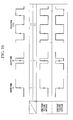
- FIG. 13A shows the waveforms and codes used in communication with another conventional noncontact RF ID system. As shown in FIG. 13B, the time intervals of the rising of the waveforms that are transmitted or received are equal.
- the transmitted and received waveforms are obtained by a combination of waveform A and waveform B.
- the waveform A is one that extends the high level state in the positive time direction by T/2 (where T is 1 cycle) from the point in time that the waveform rises and extends the low level state in the negative time direction by T/2.
- the waveform B is one that maintains the high level state in the positive time direction for time t1 from the point in time that the waveform rises, maintains a low level state for time t2 until reaching the end point of the waveform, maintains the low level state in the negative time direction for t1 from the point in time that the waveform rises, and maintains the high level state for the time t2 until reaching the starting point of the waveform.
- both waveforms A and B necessarily have a rising state transition present at the center. If each of the independent waveforms A and B is respectively assigned "0" and "1", then as shown in FIG. 14, when the waveforms B continue in succession, a rising state transition occurs at the junction between the waveforms, and thus associating the rising timing with one unit of data becomes difficult. In the case in which the waveforms B continue in succession, a rising state transition at the junction between the waveforms occurs because the waveform B starts at a high level and ends at a low level.
- a code "0" is assigned when the waveforms A continue in succession twice, while a code “1” is assigned when the waveform A continues in succession after the waveform B.
- two successive waveforms A associated with code “0” start at a low level and end at a high level
- successive waveforms B and A associated with the code "1” start at a high level and end at a high level.
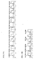
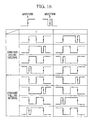
- the four combinations of all possible junctions, "00", “01”, “10", and “11" are shown in FIG. 15A to FIG. 15D.
- the combinations of waveforms A and B can have many variations, such as the case in which when the waveforms A and B are switched and waveform B continues in succession after waveform A, then a code "1" is applied.
- a combination in which the time interval of the rise is constant, is realized by a combination of a waveform pattern that starts at a low level and end at a high level and a waveform pattern that starts at a low level or a high level and ends at a level identical to the starting level.
- the communication method for a noncontact RF ID system of the present invention uses a first waveform, a second waveform, and a third waveform, wherein: one of the rising timing and the falling timing of the waveform output when communicating by using the first waveform, the second waveform, and the third waveform, becomes periodic.
- the first waveform and the second waveform may be formed by a basic waveform that has one of a rising state transition and a falling state transition at the approximate center part of the waveform;
- the third waveform may be formed by a plurality of basic waveforms that have the one state transition at the approximate center part of the waveform, and the third waveform may be formed such that the one state transition occurs only at the approximate center part of the plurality of the waveforms.
- communication may be carried out by using the third waveform in place of the first waveform and the second waveform.
- the third waveform may be a waveform that is used in place of m waveforms (here, m is a natural number equal to or greater than 2) when one of the first waveform and the second waveform continues in succession and an identical rising or falling state transition which is occurred at the approximate center part of the waveform is occurred at the connection part of the waveforms, and furthermore, a combination of the first waveform and the second waveform that includes a connection part of the waveforms that produces the state transition, consists of m waveforms.
- the first waveform may be a waveform that maintains a low level in the negative time direction for T/2 from the point in time that the waveform first rises, which is the center point of the waveform, and maintains a high level state for T/2 in the positive time direction from this center point;
- the first waveform may be an inverted waveform that maintains a low level in the negative time direction for T/2 from the point in time that the waveform first rises, which is the center point of the waveform, and maintains a high level state for T/2 in the positive time direction from this center point;
- Communication may be carried out by assigning a code "1” and a code “0” to the first waveform and the second waveform, and assigning a combination of the code "1” and the code "0” associated with the combination to the third waveform, which is used in place of the combination of the first waveform and the second waveform.
- a noncontact RF ID system of the present invention which uses the communication method may includes a clock generating device that generates an internal clock such that the state transition of the internal clock is generated in synchronism with the timing of the rise of the modulating signal; and a logic circuit that operates in synchronism with the state transition of the clock generated by the clock generating device.
- a transmitter of the present invention forms and transmits a first waveform, a second waveform, and a third waveform, wherein: the first waveform and the second waveform are formed by a basic waveform that has a state transition that either rises or falls at the approximate center part of the waveform; the third waveform is formed by a plurality of basic waveforms that have one state transition at the approximate center part of the waveform and the one state transition is generated only at the approximate center part of the plurality of basic waveforms; and transmission is carried out by using the third waveform in place of the first waveform and the second waveform in the case in which transmission is carried out using the first waveform and the second waveform and in the case in which the one state transition is generated outside the approximate center part of the waveform.
- a receiver of the present invention receives the first waveform and the second waveform, and the third waveform, wherein: the first waveform and the second waveform are formed by a basic waveform that has a state transition that either rises or falls at the approximate center part of the waveform; the third waveform is formed by a plurality of basic waveforms that have one state transition at the approximate center part of the waveform and the one state transition is generated only at the approximate center part of the plurality of basic waveforms; and in the case in which the third waveform is received, the receiver recognizes the reception of a combination of the first waveform and the second waveform in which the one state transition has occurred outside the approximate center of the basic waveform.
- the first waveform and the second waveform are formed by the basic waveform that has one of the rising or falling state transitions at the approximate center part of the waveform
- the third waveform is formed by a plurality of basic waveforms having one state transition at the approximate center part of the waveform and the one state transition occurs only at the approximate middle of the plurality of basic waveforms.
- the noncontact RF ID system of the present embodiment provides a reader 1 that reads data and a transponder 2 that receives a signal that includes data and a clock signal transmitted from the reader 1.
- the transponder 2 provides an antenna 2A, a DC power detecting circuit 200, a signal detecting circuit 201, an input amplifier 202, a clock generating circuit and demodulator 300 that do not require a phase locked loop and a reference circuit, a control logic circuit 204, and a memory 205.
- the DC power detecting circuit 200 provides a diode D1, a power source diode D2, and a power accumulating capacitor C1.
- the signal detecting circuit 201 provides a diode D1, a waveform detecting diode D3, a load capacitor C2, and an FET switch Q1.
- an amplitude modulated signal that includes the clock and data information is transmitted to the transponder 2 via the antenna A1.
- the transponder 2 receives the signal via the antenna 2A, the load is accumulated in the power accumulating capacitor C1 and the transponder 2 is activated using voltage between the both terminals of the capacitor C1 as the electric power.
- the signal detected by the waveform detecting diode D3 in the signal detecting circuit 201 is divided into the data and the clock by the clock generating circuit and the demodulator 300, and are processed by the control logic circuit 204.
- the FET switch Q1 is turned ON/OFF, and the impedance of the antenna 2A is modulated by using the load capacitor C2.
- the point on which the configuration of the noncontact RF ID system of the present embodiment differs from that of the conventional noncontact RF ID system shown in FIG. 11 is mainly that in place of a clock generating circuit and demodulator 203 that use a phase locked loop and reference circuit, a clock generating circuit and demodulator 300 that does not require a phase locked loop and a reference circuit is used.
- the other configurations are identical.
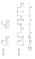
- FIGS. 2A and 2B show the waveform used in the noncontact RF ID system of the present embodiment and the waveform of the code sequence (data) communicated by assigning codes to these waveforms.
- the rising interval of the transmitted and received waveforms are equal intervals.
- the transmitted and received waveforms are obtained by combining the waveform A and waveform B shown in FIG. 2A.
- the waveform A is a waveform that extends the high level state in the positive time direction by T/2 (where T is the time for one cycle), and the low level state in the negative time direction by T/2, from the point in time that waveform rises.
- the waveform B maintains the high level state in the positive time direction for time t1 from the point in time that the waveform rises, maintains the low level state for time t2 until the end point of the waveform, maintains the low level state in the negative time direction for time t1 from the point in time that the waveform rises, and maintains a high level state for time t2 until the starting point of the waveform.
- a new waveform C in which a rising state transition does not occur at the junction between the waveforms, is assigned and transmitted in place of the continuing waveforms B.
- the waveform C is received, it is recognized that the successive waveforms B were received and demodulation is carried out.
- the waveform A is assigned code "0" and the waveform B is assigned code "1".
- the waveform C(2) is a waveform that is used in place of the two successive waveforms B, and maintains a high level state in the positive time direction for T/2 from the point in time that the waveform first rises, maintains a low level state in the negative time direction for t3, maintains a high level state for time t4 until the start point of the waveform, maintains a low level state in the negative time direction for T/2 from the point in time that the waveform rises the last time, maintains a high level state in the positive direction for t3, and maintains a low level state for time t4 until the end point of the waveform.
- FIG. 3 shows an example of a waveform C(3), which is assigned in place of three successive waveforms B.
- This waveform C(3) is a waveform that, in place of three successive waveforms B, maintains a high level state in the positive time direction for t6 from the point in time that the waveform first rises, maintains a low level state in the negative time direction for t3, maintains a high level state for time t4 until the start-point of the waveform, maintains a low level state in the negative time direction for t5 from the point in time that the waveform rises for the second time, maintains a high level state in the positive time direction for time t5, maintains a low level state in the negative time direction for t6 from the pint in time that the waveform rises the last time, maintains a high level state in the positive time direction for time t3, and maintains a low level state for time t4 until the end point of the waveform.
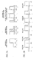
- FIG. 4 shows an example of waveform C(4) assigned in place of four successive waveforms B.
- the waveform C(4) is a waveform that, in place of four successive waveforms B, maintains a high level state in the positive time direction for t6 from the point in time that the waveform first rises, maintains a low level state in the negative time direction for t3, maintains a high level state for time t4 until the start point of the waveform, maintains a low level state in the negative time direction for t5 from the point in time that the waveform rises for the second time, maintains a high level state in the positive time direction for time T/2, maintains a low level state in the negative time direction for T/2 from the point in time that the waveform rises for the third time, maintains a high level state in the positive time direction for time t5, maintains a low level state in the negative time direction for t6 from the point in time the waveform rises the last time, maintains a high level state in the positive time direction for time
- FIG. 5 shows an example of a waveform C(5) that is assigned in place of five successive waveforms B.
- the waveform C(5) is a waveform that, in place of five successive waveforms B, maintains a high level state in the positive time direction for t6 from the point in time that the waveform first rises, maintains a low level state in the negative time direction for t3, maintains a high level state for t4 until the start point of the waveform, maintains a low level state in the negative time direction for t5 from the point in time that the waveform rises for the second time, maintains a high level state in the positive time direction for time t8, maintains a low level state in the negative time direction for t7 from the point in time that the waveform rises for the third time, maintains a high level state in the positive time direction for time t7, maintains a low level state in the negative time direction for t8 from the point in time that the waveform rises for the fourth time, maintains a high level state in
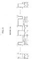
- FIG. 6 shows an example of a waveform C(6) that is assigned in place of six successive waveforms B.
- the waveform C(6) is a waveform that, in place of six successive waveforms B, maintains a high level state in the positive time direction for t6 from the point in time that the waveform first rises, maintains a low level state in the negative time direction for t3, maintains a high level state for time t4 until the start point of the waveform, maintains a low level state in the negative time direction for t5 from the point in time that the waveform rises for the second time, maintains a high level state in the positive time direction for time t8, maintains a low level state in the negative time direction for t7 from the point in time that the waveform rises for the third time, maintains a high level state in the positive time direction for time T/2, maintains a low level state in the negative time direction for T/2 from the point in time that the waveform rises for the fourth time, maintains a high level state in the
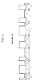
- FIG. 7 shows an example of a waveform C(2n + 1), which is assigned in place of (2n + 1) successive waveforms B (where n is a natural number).
- the waveform C(2n + 1) is a waveform that, in place of (2n + 1) successive waveforms B, maintains a high level state in the positive time direction for t6 from the point in time that the waveform first rises, maintains a low level state in the negative time direction for t3, maintains a high level state for time t4 until the starting point of the waveform, maintains a high level state in the positive time direction for t ⁇ 2 (n - k) + 6 ⁇ from the point in time that the waveform rises for the (n + 1 - k)th time, maintains a low level state in the negative time direction for t ⁇ 2 (n - k) + 3 ⁇ , maintains a high level state in the positive time direction for t ⁇ 2 (n - 1) + 5 ⁇ from the point in time that the waveform rises for the (n + 1)th time, maintains a low level state in the negative time direction for t ⁇ 2 (n - 1) + 5 ⁇ , maintains a high level state in
- FIG. 8 shows an example of a waveform C(2n), which is assigned in place of (2n) successive waveforms B (where n is a natural number).
- the waveform C(2n) is a waveform that, in place of (2n) successive waveforms B, maintains a high level state in the positive time direction for t6 from the point in time that the waveform first rises, maintains a low level state in the negative time direction for t3, maintains a high level state for t4 until the starting point of the waveform, maintains a high level state in the positive time direction for t ⁇ 2 (n - k) + 6 ⁇ from the point in time that the waveform rises for the (n + 1 - k)th time, maintains a low level state in the negative time direction for t ⁇ 2 (n - k) + 3 ⁇ , maintains a high level state in the positive time direction for T/2 from the point in time that the waveform rises for the nth time, maintains a low level state in the negative time direction for t ⁇ 2 (n - 1) + 3 ⁇ , maintains a high level state in the positive time direction for t ⁇ 2 (n - 1) +
- a circuit that detects a rising transition it is possible to generate easily a clock signal that is in synchronism with data.
- FIGS. 9A and 9B show a comparative example of the code length in the case in which communication is carried out with a noncontact RF ID system that uses another conventional example and the noncontact RF ID system of the present embodiment.
- the present embodiment it is possible to reduce by half the code length when using the communication method of another conventional example, and thereby it is possible to realize an improvement in transmission efficiency due to encoding.
- the combination of waveforms A and B can bring about a wide variation by replacing the waveforms A and B.
- waveforms that are completely right-left symmetrical are used for each of the waveforms A, B, and C, but when constructing an actual circuit, because of influences such as delay characteristics of each of the circuits used for demodulation, time constants and the like, it is not always necessary to use completely right-left symmetric waveforms.
- a waveform in which the rising and falling timings are substantially constant and the duty ratio is maintained at approximately 50% can be used. In this case, it is possible to minimize the errors due to amplitude fluctuation.
- the embodiment described above illustrates the present invention, but does not limit the present invention.
- the present invention can be implemented by various other modifications and alterations.
- amplitude modulation it is possible to use frequency modulation or phase modulation as a modulation method.
- a modulation method that is a combination of amplitude modulation, frequency modulation, and phase modulation.
- the security may be improved with respect to tapping and impersonation by encrypting the signal sequence, and encoding may be carried out with the object of error detection and error correction.
- a first waveform and a second waveform are formed by basic waveforms having one of rising or falling state transitions at the approximate center part of the waveform, and a third waveform is formed by a plurality of basic waveforms having one state transition at the approximate center part of the waveforms.
- a state transition in the third waveform is generated only at the approximate center part of the plurality of basic waveforms, and when communication is carried out by using the first waveform and the second waveform, in the case in which one state transition is generated outside the approximate center part of the waveform (for example, the case of successive second waveforms), transmission is carried out by assigning the third waveform that does not generate a rising (or falling) state transition at the junction between the waveforms on the transmission side in place of the successive second waveforms, and at the reception side, when the third waveform has been received, demodulation is carried out by recognizing the reception of the successive second waveforms.
- improvement in the transmission efficiency due to encoding can be realized without using a plurality of phase locked loops and reference circuits, and it is possible to realize a communication method for a noncontact RF ID system, a noncontact RF ID system, and a transmitter and receiver.
Landscapes
- Engineering & Computer Science (AREA)
- Physics & Mathematics (AREA)
- Spectroscopy & Molecular Physics (AREA)
- Computer Networks & Wireless Communication (AREA)
- Signal Processing (AREA)
- Artificial Intelligence (AREA)
- Computer Vision & Pattern Recognition (AREA)
- General Physics & Mathematics (AREA)
- Theoretical Computer Science (AREA)
- Near-Field Transmission Systems (AREA)
- Dc Digital Transmission (AREA)
- Synchronisation In Digital Transmission Systems (AREA)
Abstract
Description
Claims (9)
- A communication method for a noncontact RF ID system that uses a first waveform, a second waveform, and a third waveform, wherein:one of the rising timing and the falling timing of the waveform output when communicating by using the first waveform, the second waveform, and the third waveform, becomes periodic.
- The communication method for a noncontact RF ID system according to claim 1, wherein:the first waveform and the second waveform are formed by a basic waveform that has one of a rising state transition and a falling state transition at the approximate center part of the waveform;the third waveform is formed by a plurality of basic waveforms that have said one state transition at the approximate center part of the waveform, and the third waveform is formed such that said one state transition occurs only at the approximate center part of the plurality of the waveforms; andin the case in which said state transition occurs outside the approximate center of the basic waveform when communicating by using the first waveform and the second waveform, communication is carried out by using the third waveform in place of the first waveform and the second waveform.
- The communication method for a noncontact RF ID system according to claim 2, wherein:the third waveform is a waveform that is used in place of m waveforms (here, m is a natural number equal to or greater than 2) when one of the first waveform and the second waveform continues in succession and an identical rising or falling state transition which is occurred at the approximate center part of the waveform is occurred at the connection part of the waveforms, and furthermore, a combination of the first waveform and the second waveform that includes a connection part of the waveforms that produces the state transition, consists of m waveforms.
- The communication method for a noncontact RF ID system according to claim 3, wherein:in the case in which the state transition is rising, the first waveform is a waveform that maintains a low level in the negative time direction for T/2 from the point in time that the waveform first rises, which is the center point of the waveform, and maintains a high level state for T/2 in the positive time direction from this center point;the second waveform is a waveform that maintains a high level state in the positive time direction for t1 from the point in time that the waveform first rises, which is the center point of the waveform, maintains a low level state for time t2 until the end point of the waveform, maintains a low level state in the negative time direction for time t1 from the center point of the waveform, and maintains a high level state for time t2 until the starting point of the waveform (here, t denotes time, T denotes one cycle of the first and second waveforms, and t1 + t2 = T/2); andthe third waveform is a C(2n) waveform which, in the case in which m=2n, maintains a high level state in the positive time direction for t6 from the point in time that the waveform first rises; maintains a low level state in the negative time direction for t3 from the point in time that the waveform first rises; maintains a high level state for time t4 until the starting point of the waveform; maintains a high level state in the positive time direction for t{2 (n - k) + 6} from the point in time that the waveform rises for the (n + 1 - k)th time; maintains a low level state for t {2 (n - k) + 3} in the negative time direction from the point in time that the waveform rises for the (n + 1 - k)th time; maintains a high level state in the positive time direction for T/2 from the point in time that the waveform rises for the nth time; maintains a low level state in the negative time direction for t{2 (n - 1) + 3} from the point in time that the waveform rises for the nth time; maintains a high level state in the positive time direction for t{2 (n - 1) +3} from the point in time that the waveform rises for the (n + 1)th time; maintains a low level state in the negative time direction for T/2 from the point in time that the waveform rises for the (n + 1)th time; maintains a high level state in the positive time direction for t{2 (n - k) + 3} from the point in time that the waveform rises for the (n + k)th time; maintains a low level state in the negative time direction for t {2 (n - k) + 6} from the point in time that the waveform rises for the (n + k)th time; maintains a low level state in the negative time direction for t6 from the point in time that the waveform rises the last time;
maintains a high level state in the positive time direction for t3 from the point in time that the waveform rises the last time; and maintains a low level state for time t4 until the end point of the waveform, where n and k are natural numbers; n ≥ k ≥ 1; t is time; T is one cycle of the first and second waveforms; and t3 + t4 = T/2; t{2 (n - k) + 5} + t{2 (n - k) + 6} = T (when n and k ≥ 2); andin the case in which m = 2n + 1, the third waveform is a C(2n + 1) waveform that maintains a high level state in the positive time direction for t6 from the point in time that the waveform first rises; maintains a low level state in the negative time direction for t3 from the point in time that the waveform first rises; maintains a high level state for t4 from the starting point of the waveform; maintains a high level state in the positive time direction for t{2 (n - k) + 6} from the point in time that the waveform rises for the (n + 1 - k)th time; maintains a low level state in the negative time direction for t{2 (n - k) + 3} from the point in time that the waveform rises for the (n + 1 - k)th time; maintains a high level state in the positive time direction for t{2 (n - 1) + 5} from the point in time that the waveform rises for the (n + 1)th time; maintains a low level state in the negative time direction for t{2 (n - 1) + 5} from the point in time that the waveform rises for the (n + 1)th time; maintains a high level state in the positive time direction for t{2 (n - k) + 3} from the point in time that the waveform rises for the (n + 1 + k)th time; maintains a low level state in the negative time direction for t{2 (n - k) + 6} from the point in time that the waveform rises for the (n + 1 + k)th time; maintains a low level state in the negative time direction for t6 from the point in time that the waveform rises the last time; maintains a high level state in the positive time direction for time t3 from the point in time that the waveform rises the last time; and maintains a low level state for t4 until the end point of the waveform; (where n and k are natural numbers, n ≥ k ≥ 1, t is time, T is one cycle of the first and second waveforms, t3 + t4 = T/2, and t{2(n - k) + 5} + t{2(n - k) + 6} = T). - The communication method for a noncontact RF ID system according to claim 3, wherein:in the case in which the state transition is a falling state transition, the first waveform is an inverted waveform that maintains a low level in the negative time direction for T/2 from the point in time that the waveform first rises, which is the center point of the waveform, and maintains a high level state for T/2 in the positive time direction from this center point;the second waveform is an inverted waveform that maintains a high level state in the positive time direction for t1 from the point in time that the waveform first rises, which is the center point of the waveform, maintains a low level state for time t2 until the end point of the waveform, maintains a low level state in the negative time direction for time t1 from the center point of the waveform, and maintains a high level state for time t2 until the starting point of the waveform (here, t denotes time, T denotes one cycle of the first and second waveforms, and t1 + t2 = T/2); andthe third waveform is an inverted C(2n) waveform which, in the case in which m=2n, maintains a high level state in the positive time direction for t6 from the point in time that the waveform first rises; maintains a low level state in the negative time direction for t3 from the point in time that the waveform first rises; maintains a high level state for time t4 until the starting point of the waveform; maintains a high level state in the positive time direction for t{2 (n - k) + 6} from the point in time that the waveform rises for the (n + 1 - k)th time; maintains a low level state for t {2 (n - k) + 3} in the negative time direction from the point in time that the waveform rises for the (n + 1 - k)th time; maintains a high level state in the positive time direction for T/2 from the point in time that the waveform rises for the nth time; maintains a low level state in the negative time direction for t{2 (n - 1) + 3} from the point in time that the waveform rises for the nth time; maintains a high level state in the positive time direction for t{2 (n - 1) +3} from the point in time that the waveform rises for the (n + 1)th time; maintains a low level state in the negative time direction for T/2 from the point in time that the waveform rises for the (n + 1)th time; maintains a high level state in the positive time direction for t{2 (n - k) + 3} from the point in time that the waveform rises for the (n + k)th time; maintains a low level state in the negative time direction for t {2 (n - k) + 6} from the point in time that the waveform rises for the (n + k)th time; maintains a low level state in the negative time direction for t6 from the point in time that the waveform rises the last time; maintains a high level state in the positive time direction for t3 from the point in time that the waveform rises the last time; and maintains a low level state for time t4 until the end point of the waveform, where n and k are natural numbers; n ≥ k ≥ 1; t is time; T is one cycle of the first and second waveforms; and t3 + t4 = T/2; t{2 (n - k) + 5} + t{2 (n - k) + 6} = T (when n and k ≥ 2); andin the case in which m = 2n + 1, the third waveform is an inverted C(2n + 1) waveform that maintains a high level state in the positive time direction for t6 from the point in time that the waveform first rises; maintains a low level state in the negative time direction for t3 from the point in time that the waveform first rises; maintains a high level state for t4 from the starting point of the waveform; maintains a high level state in the positive time direction for t{2 (n - k) + 6} from the point in time that the waveform rises for the (n + 1 - k)th time; maintains a low level state in the negative time direction for t{2 (n - k) + 3} from the point in time that the waveform rises for the (n + 1 - k)th time; maintains a high level state in the positive time direction for t{2 (n - 1) + 5} from the point in time that the waveform rises for the (n + 1)th time; maintains a low level state in the negative time direction for t{2 (n - 1) + 5} from the point in time that the waveform rises for the (n + 1)th time; maintains a high level state in the positive time direction for t{2 (n - k) + 3} from the point in time that the waveform rises for the (n + 1 + k)th time; maintains a low level state in the negative time direction for t{2 (n - k) + 6} from the point in time that the waveform rises for the (n + 1 + k)th time; maintains a low level state in the negative time direction for t6 from the point in time that the waveform rises the last time; maintains a high level state in the positive time direction for time t3 from the point in time that the waveform rises the last time; and maintains a low level state for t4 until the end point of the waveform; (where n and k are natural numbers, n ≥ k ≥ 1, t is time, T is one cycle of the first and second waveforms, t3 + t4 = T/2, and t{2 (n - k) + 5} +t{2 (n-k) +6} = T).
- The communication method for a noncontact RF ID system according to any one of claims 2 to 5, wherein:communication is carried out by assigning a code "1" and a code "0" to the first waveform and the second waveform, and assigning a combination of the code "1" and the code "0" associated with the combination to the third waveform, which is used in place of the combination of the first waveform and the second waveform.
- A noncontact RF ID system which uses the communication method according to any one of claims 1 to 5, comprising:a clock generating device that generates an internal clock such that the state transition of the internal clock is generated in synchronism with the timing of the rise of the modulating signal; anda logic circuit that operates in synchronism with the state transition of the clock generated by the clock generating device.
- A transmitter that forms and transmits a first waveform, a second waveform, and a third waveform, wherein:the first waveform and the second waveform are formed by a basic waveform that has a state transition that either rises or falls at the approximate center part of the waveform;the third waveform is formed by a plurality of basic waveforms that have one state transition at the approximate center part of the waveform and said one state transition is generated only at the approximate center part of the plurality of basic waveforms; andtransmission is carried out by using the third waveform in place of the first waveform and the second waveform in the case in which transmission is carried out using the first waveform and the second waveform and in the case in which said one state transition is generated outside the approximate center part of the waveform.
- A receiver that receives the first waveform and the second waveform, and the third waveform, wherein:the first waveform and the second waveform are formed by a basic waveform that has a state transition that either rises or falls at the approximate center part of the waveform;the third waveform is formed by a plurality of basic waveforms that have one state transition at the approximate center part of the waveform and the one state transition is generated only at the approximate center part of the plurality of basic waveforms; andin the case in which the third waveform is received, the receiver recognizes the reception of a combination of the first waveform and the second waveform in which said one state transition has occurred outside the approximate center of the basic waveform.
Applications Claiming Priority (3)
| Application Number | Priority Date | Filing Date | Title |
|---|---|---|---|
| JP2003007474 | 2003-01-15 | ||
| JP2003007474 | 2003-01-15 | ||
| PCT/JP2004/000190 WO2004064346A1 (en) | 2003-01-15 | 2004-01-14 | Non-contact rf id system communication method, non-contact rf id system, transmitter, and receiver |
Publications (3)
| Publication Number | Publication Date |
|---|---|
| EP1585280A1 true EP1585280A1 (en) | 2005-10-12 |
| EP1585280A4 EP1585280A4 (en) | 2011-09-21 |
| EP1585280B1 EP1585280B1 (en) | 2013-03-13 |
Family
ID=32709116
Family Applications (1)
| Application Number | Title | Priority Date | Filing Date |
|---|---|---|---|
| EP04702051A Expired - Lifetime EP1585280B1 (en) | 2003-01-15 | 2004-01-14 | Non-contact RF ID system communication method, non-contact RF ID system, transmitter, and receiver |
Country Status (5)
| Country | Link |
|---|---|
| US (2) | US7738838B2 (en) |
| EP (1) | EP1585280B1 (en) |
| JP (1) | JP3803364B2 (en) |
| CN (1) | CN1698330B (en) |
| WO (1) | WO2004064346A1 (en) |
Families Citing this family (5)
| Publication number | Priority date | Publication date | Assignee | Title |
|---|---|---|---|---|
| US9537704B2 (en) | 2006-05-24 | 2017-01-03 | At&T Intellectual Property I, L.P. | Method and apparatus for migrating active communication session between terminals |
| CN101620663B (en) | 2008-07-02 | 2012-05-09 | 中兴通讯股份有限公司 | Data coding method in passive radio frequency identification system |
| JP5184278B2 (en) * | 2008-09-22 | 2013-04-17 | 株式会社横須賀テレコムリサーチパーク | Waveform generation circuit and tag communication device |
| CN103988441A (en) * | 2011-12-16 | 2014-08-13 | 英特尔公司 | Wireless communication device using time-varying antenna module |
| US20140065982A1 (en) | 2012-09-05 | 2014-03-06 | Seong-Youp Suh | Plug-and-play time-variant antenna module for wireless communication devices |
Family Cites Families (11)
| Publication number | Priority date | Publication date | Assignee | Title |
|---|---|---|---|---|
| JPS5413708A (en) | 1977-07-04 | 1979-02-01 | Nippon Telegr & Teleph Corp <Ntt> | Code conversion system |
| GB2079566B (en) * | 1980-05-16 | 1985-01-09 | Racal Recorders Ltd | Data encoding and/or decoding |
| US5058141A (en) * | 1990-03-01 | 1991-10-15 | Ag Communication Systems Corporation | Single circuit for detecting a frame synchronization pattern and generating control signals |
| JP4001955B2 (en) | 1996-06-18 | 2007-10-31 | ソニー株式会社 | Digital signal transmission method |
| TW391084B (en) * | 1997-09-29 | 2000-05-21 | Sharp Kk | Data communication receiving element |
| JP2002507075A (en) * | 1998-03-11 | 2002-03-05 | トムソン ライセンシング ソシエテ アノニム | Digital signal modulation system |
| JP3531477B2 (en) | 1998-06-05 | 2004-05-31 | 株式会社日立製作所 | Contactless card communication method and integrated circuit used for the communication |
| US6943678B2 (en) * | 2000-01-24 | 2005-09-13 | Nextreme, L.L.C. | Thermoformed apparatus having a communications device |
| EP1362320B1 (en) * | 2001-02-12 | 2011-02-09 | Symbol Technologies, Inc. | Radio frequency identification architecture |
| WO2002065690A1 (en) * | 2001-02-14 | 2002-08-22 | Thine Electronics, Inc. | Semiconductor integrated circuit |
| US20030011474A1 (en) * | 2001-07-13 | 2003-01-16 | Ng Sing King | Circuit and method for electronic security seal |
-
2004
- 2004-01-14 CN CN200480000101.3A patent/CN1698330B/en not_active Expired - Fee Related
- 2004-01-14 WO PCT/JP2004/000190 patent/WO2004064346A1/en active Application Filing
- 2004-01-14 EP EP04702051A patent/EP1585280B1/en not_active Expired - Lifetime
- 2004-01-14 JP JP2005507675A patent/JP3803364B2/en not_active Expired - Fee Related
- 2004-01-14 US US10/519,858 patent/US7738838B2/en not_active Expired - Fee Related
-
2010
- 2010-06-11 US US12/813,928 patent/US20100245051A1/en not_active Abandoned
Also Published As
| Publication number | Publication date |
|---|---|
| CN1698330A (en) | 2005-11-16 |
| JP3803364B2 (en) | 2006-08-02 |
| US20100245051A1 (en) | 2010-09-30 |
| CN1698330B (en) | 2010-04-28 |
| EP1585280B1 (en) | 2013-03-13 |
| EP1585280A4 (en) | 2011-09-21 |
| US7738838B2 (en) | 2010-06-15 |
| JPWO2004064346A1 (en) | 2006-05-18 |
| WO2004064346A1 (en) | 2004-07-29 |
| US20050253716A1 (en) | 2005-11-17 |
Similar Documents
| Publication | Publication Date | Title |
|---|---|---|
| US8044801B1 (en) | RFID tag with double-switch rectifier | |
| US6765959B1 (en) | Communication method of contactless ID card and integrated circuit used in communication method | |
| JP2007518339A (en) | Radio frequency recognition and communication element | |
| KR20050027377A (en) | Contactless integrated circuit card with real-time protocol switching function and card system including the same | |
| JPH0946282A (en) | Data transfer system and demodulator therefor | |
| US20100245051A1 (en) | Communication Method for Noncontact RF ID System, Noncontact RF ID System, and Transmitter and Receiver | |
| US8754753B2 (en) | Resistive and capacitive modulation in an electromagnetic transponder | |
| US7760835B2 (en) | Wireless communications devices, methods of processing a wireless communication signal, wireless communication synchronization methods and a radio frequency identification device communication method | |
| US20210248332A1 (en) | Radio Transponder and Method for Data Transmission Between a Radio Transponder Reader and the Radio Transponder | |
| JP2008028791A (en) | Class E amplifier, reader / writer and document management system using the same | |
| US8749352B2 (en) | Method for coded data transmission between a base station and at least one transponder within a wireless data transmission system | |
| US6775323B1 (en) | Data coding system | |
| US8766776B2 (en) | Transponder unit | |
| WO2008140156A1 (en) | Rf reader capable of detecting rf signal and existence of rf card and the method thereof | |
| US9729359B1 (en) | Methods and apparatus for transponder oscillator with optimized timing | |
| JP2005151033A (en) | Vpm modulation system in rfid communication | |
| US20240330613A1 (en) | Reception circuit and smart card including the same | |
| JP2005151075A (en) | Asynchronous communication system by pulse gap signal in rfid communication | |
| EP1512118B1 (en) | Passive data carrier with signal evaluation means for evaluating information of a self-clocking signal | |
| Yokojima et al. | Novel encoding method for non-contact IC card or RFID systems | |
| KR19990057842A (en) | RF Data Modulation Circuit and Modulation Method of Contactless Smart Card | |
| JP2003036426A (en) | Contactless IC card and data processing method thereof |
Legal Events
| Date | Code | Title | Description |
|---|---|---|---|
| PUAI | Public reference made under article 153(3) epc to a published international application that has entered the european phase |
Free format text: ORIGINAL CODE: 0009012 |
|
| 17P | Request for examination filed |
Effective date: 20041028 |
|
| AK | Designated contracting states |
Kind code of ref document: A1 Designated state(s): AT BE BG CH CY CZ DE DK EE ES FI FR GB GR HU IE IT LI LU MC NL PT RO SE SI SK TR |
|
| AX | Request for extension of the european patent |
Extension state: AL LT LV MK |
|
| DAX | Request for extension of the european patent (deleted) | ||
| RBV | Designated contracting states (corrected) |
Designated state(s): DE FR GB IT |
|
| A4 | Supplementary search report drawn up and despatched |
Effective date: 20110822 |
|
| RIC1 | Information provided on ipc code assigned before grant |
Ipc: G06K 7/00 20060101ALI20110816BHEP Ipc: H04L 25/38 20060101ALI20110816BHEP Ipc: H04L 25/49 20060101AFI20110816BHEP |
|
| 17Q | First examination report despatched |
Effective date: 20120316 |
|
| GRAP | Despatch of communication of intention to grant a patent |
Free format text: ORIGINAL CODE: EPIDOSNIGR1 |
|
| GRAS | Grant fee paid |
Free format text: ORIGINAL CODE: EPIDOSNIGR3 |
|
| GRAA | (expected) grant |
Free format text: ORIGINAL CODE: 0009210 |
|
| RIN1 | Information on inventor provided before grant (corrected) |
Inventor name: TUBAKI, TOSHIMITSU, C/O NTT INTELLECTUAL PROPERTY Inventor name: SHIMIZU, MASASHI, C/O NTT INTELLECTUAL PROPERTY CE Inventor name: HAYASHI, HITOSHI, C/O NTT INTELLECTUAL PROPERTY CE |
|
| AK | Designated contracting states |
Kind code of ref document: B1 Designated state(s): DE FR GB IT |
|
| REG | Reference to a national code |
Ref country code: GB Ref legal event code: FG4D |
|
| REG | Reference to a national code |
Ref country code: DE Ref legal event code: R096 Ref document number: 602004041325 Country of ref document: DE Effective date: 20130508 |
|
| PLBE | No opposition filed within time limit |
Free format text: ORIGINAL CODE: 0009261 |
|
| STAA | Information on the status of an ep patent application or granted ep patent |
Free format text: STATUS: NO OPPOSITION FILED WITHIN TIME LIMIT |
|
| 26N | No opposition filed |
Effective date: 20131216 |
|
| PG25 | Lapsed in a contracting state [announced via postgrant information from national office to epo] |
Ref country code: IT Free format text: LAPSE BECAUSE OF FAILURE TO SUBMIT A TRANSLATION OF THE DESCRIPTION OR TO PAY THE FEE WITHIN THE PRESCRIBED TIME-LIMIT Effective date: 20130313 |
|
| REG | Reference to a national code |
Ref country code: DE Ref legal event code: R097 Ref document number: 602004041325 Country of ref document: DE Effective date: 20131216 |
|
| REG | Reference to a national code |
Ref country code: DE Ref legal event code: R119 Ref document number: 602004041325 Country of ref document: DE |
|
| GBPC | Gb: european patent ceased through non-payment of renewal fee |
Effective date: 20140114 |
|
| PG25 | Lapsed in a contracting state [announced via postgrant information from national office to epo] |
Ref country code: DE Free format text: LAPSE BECAUSE OF NON-PAYMENT OF DUE FEES Effective date: 20140801 |
|
| REG | Reference to a national code |
Ref country code: FR Ref legal event code: ST Effective date: 20140930 |
|
| REG | Reference to a national code |
Ref country code: DE Ref legal event code: R119 Ref document number: 602004041325 Country of ref document: DE Effective date: 20140801 |
|
| PG25 | Lapsed in a contracting state [announced via postgrant information from national office to epo] |
Ref country code: GB Free format text: LAPSE BECAUSE OF NON-PAYMENT OF DUE FEES Effective date: 20140114 Ref country code: FR Free format text: LAPSE BECAUSE OF NON-PAYMENT OF DUE FEES Effective date: 20140131 |