EP1585269A2 - Wireless personal local area network - Google Patents
Wireless personal local area network Download PDFInfo
- Publication number
- EP1585269A2 EP1585269A2 EP05014083A EP05014083A EP1585269A2 EP 1585269 A2 EP1585269 A2 EP 1585269A2 EP 05014083 A EP05014083 A EP 05014083A EP 05014083 A EP05014083 A EP 05014083A EP 1585269 A2 EP1585269 A2 EP 1585269A2
- Authority
- EP
- European Patent Office
- Prior art keywords
- network
- network device
- radio
- microlan
- devices
- Prior art date
- Legal status (The legal status is an assumption and is not a legal conclusion. Google has not performed a legal analysis and makes no representation as to the accuracy of the status listed.)
- Granted
Links
Images


Classifications
-
- H—ELECTRICITY
- H04—ELECTRIC COMMUNICATION TECHNIQUE
- H04W—WIRELESS COMMUNICATION NETWORKS
- H04W52/00—Power management, e.g. TPC [Transmission Power Control], power saving or power classes
- H04W52/04—TPC
- H04W52/30—TPC using constraints in the total amount of available transmission power
- H04W52/34—TPC management, i.e. sharing limited amount of power among users or channels or data types, e.g. cell loading
- H04W52/343—TPC management, i.e. sharing limited amount of power among users or channels or data types, e.g. cell loading taking into account loading or congestion level
-
- G—PHYSICS
- G08—SIGNALLING
- G08C—TRANSMISSION SYSTEMS FOR MEASURED VALUES, CONTROL OR SIMILAR SIGNALS
- G08C17/00—Arrangements for transmitting signals characterised by the use of a wireless electrical link
- G08C17/02—Arrangements for transmitting signals characterised by the use of a wireless electrical link using a radio link
-
- H—ELECTRICITY
- H04—ELECTRIC COMMUNICATION TECHNIQUE
- H04B—TRANSMISSION
- H04B17/00—Monitoring; Testing
- H04B17/0082—Monitoring; Testing using service channels; using auxiliary channels
- H04B17/0085—Monitoring; Testing using service channels; using auxiliary channels using test signal generators
-
- H—ELECTRICITY
- H04—ELECTRIC COMMUNICATION TECHNIQUE
- H04B—TRANSMISSION
- H04B17/00—Monitoring; Testing
- H04B17/30—Monitoring; Testing of propagation channels
- H04B17/309—Measuring or estimating channel quality parameters
- H04B17/318—Received signal strength
-
- H—ELECTRICITY
- H04—ELECTRIC COMMUNICATION TECHNIQUE
- H04L—TRANSMISSION OF DIGITAL INFORMATION, e.g. TELEGRAPHIC COMMUNICATION
- H04L1/00—Arrangements for detecting or preventing errors in the information received
- H04L1/0001—Systems modifying transmission characteristics according to link quality, e.g. power backoff
- H04L1/0002—Systems modifying transmission characteristics according to link quality, e.g. power backoff by adapting the transmission rate
-
- H—ELECTRICITY
- H04—ELECTRIC COMMUNICATION TECHNIQUE
- H04L—TRANSMISSION OF DIGITAL INFORMATION, e.g. TELEGRAPHIC COMMUNICATION
- H04L1/00—Arrangements for detecting or preventing errors in the information received
- H04L1/0001—Systems modifying transmission characteristics according to link quality, e.g. power backoff
- H04L1/0015—Systems modifying transmission characteristics according to link quality, e.g. power backoff characterised by the adaptation strategy
- H04L1/0017—Systems modifying transmission characteristics according to link quality, e.g. power backoff characterised by the adaptation strategy where the mode-switching is based on Quality of Service requirement
-
- H—ELECTRICITY
- H04—ELECTRIC COMMUNICATION TECHNIQUE
- H04L—TRANSMISSION OF DIGITAL INFORMATION, e.g. TELEGRAPHIC COMMUNICATION
- H04L1/00—Arrangements for detecting or preventing errors in the information received
- H04L1/0001—Systems modifying transmission characteristics according to link quality, e.g. power backoff
- H04L1/0023—Systems modifying transmission characteristics according to link quality, e.g. power backoff characterised by the signalling
- H04L1/0025—Transmission of mode-switching indication
-
- H—ELECTRICITY
- H04—ELECTRIC COMMUNICATION TECHNIQUE
- H04L—TRANSMISSION OF DIGITAL INFORMATION, e.g. TELEGRAPHIC COMMUNICATION
- H04L1/00—Arrangements for detecting or preventing errors in the information received
- H04L1/0001—Systems modifying transmission characteristics according to link quality, e.g. power backoff
- H04L1/0023—Systems modifying transmission characteristics according to link quality, e.g. power backoff characterised by the signalling
- H04L1/0032—Without explicit signalling
-
- H—ELECTRICITY
- H04—ELECTRIC COMMUNICATION TECHNIQUE
- H04W—WIRELESS COMMUNICATION NETWORKS
- H04W28/00—Network traffic management; Network resource management
- H04W28/16—Central resource management; Negotiation of resources or communication parameters, e.g. negotiating bandwidth or QoS [Quality of Service]
- H04W28/18—Negotiating wireless communication parameters
- H04W28/22—Negotiating communication rate
-
- H—ELECTRICITY
- H04—ELECTRIC COMMUNICATION TECHNIQUE
- H04W—WIRELESS COMMUNICATION NETWORKS
- H04W52/00—Power management, e.g. TPC [Transmission Power Control], power saving or power classes
- H04W52/04—TPC
- H04W52/30—TPC using constraints in the total amount of available transmission power
- H04W52/34—TPC management, i.e. sharing limited amount of power among users or channels or data types, e.g. cell loading
- H04W52/346—TPC management, i.e. sharing limited amount of power among users or channels or data types, e.g. cell loading distributing total power among users or channels
-
- G—PHYSICS
- G08—SIGNALLING
- G08C—TRANSMISSION SYSTEMS FOR MEASURED VALUES, CONTROL OR SIMILAR SIGNALS
- G08C2201/00—Transmission systems of control signals via wireless link
- G08C2201/20—Binding and programming of remote control devices
-
- H—ELECTRICITY
- H04—ELECTRIC COMMUNICATION TECHNIQUE
- H04L—TRANSMISSION OF DIGITAL INFORMATION, e.g. TELEGRAPHIC COMMUNICATION
- H04L12/00—Data switching networks
- H04L12/28—Data switching networks characterised by path configuration, e.g. LAN [Local Area Networks] or WAN [Wide Area Networks]
- H04L12/40—Bus networks
- H04L12/403—Bus networks with centralised control, e.g. polling
-
- H—ELECTRICITY
- H04—ELECTRIC COMMUNICATION TECHNIQUE
- H04L—TRANSMISSION OF DIGITAL INFORMATION, e.g. TELEGRAPHIC COMMUNICATION
- H04L69/00—Network arrangements, protocols or services independent of the application payload and not provided for in the other groups of this subclass
- H04L69/18—Multiprotocol handlers, e.g. single devices capable of handling multiple protocols
-
- H—ELECTRICITY
- H04—ELECTRIC COMMUNICATION TECHNIQUE
- H04W—WIRELESS COMMUNICATION NETWORKS
- H04W28/00—Network traffic management; Network resource management
- H04W28/02—Traffic management, e.g. flow control or congestion control
- H04W28/10—Flow control between communication endpoints
-
- H—ELECTRICITY
- H04—ELECTRIC COMMUNICATION TECHNIQUE
- H04W—WIRELESS COMMUNICATION NETWORKS
- H04W52/00—Power management, e.g. TPC [Transmission Power Control], power saving or power classes
- H04W52/02—Power saving arrangements
- H04W52/0209—Power saving arrangements in terminal devices
- H04W52/0261—Power saving arrangements in terminal devices managing power supply demand, e.g. depending on battery level
- H04W52/0287—Power saving arrangements in terminal devices managing power supply demand, e.g. depending on battery level changing the clock frequency of a controller in the equipment
- H04W52/029—Power saving arrangements in terminal devices managing power supply demand, e.g. depending on battery level changing the clock frequency of a controller in the equipment reducing the clock frequency of the controller
-
- H—ELECTRICITY
- H04—ELECTRIC COMMUNICATION TECHNIQUE
- H04W—WIRELESS COMMUNICATION NETWORKS
- H04W84/00—Network topologies
- H04W84/02—Hierarchically pre-organised networks, e.g. paging networks, cellular networks, WLAN [Wireless Local Area Network] or WLL [Wireless Local Loop]
- H04W84/10—Small scale networks; Flat hierarchical networks
- H04W84/12—WLAN [Wireless Local Area Networks]
-
- Y—GENERAL TAGGING OF NEW TECHNOLOGICAL DEVELOPMENTS; GENERAL TAGGING OF CROSS-SECTIONAL TECHNOLOGIES SPANNING OVER SEVERAL SECTIONS OF THE IPC; TECHNICAL SUBJECTS COVERED BY FORMER USPC CROSS-REFERENCE ART COLLECTIONS [XRACs] AND DIGESTS
- Y02—TECHNOLOGIES OR APPLICATIONS FOR MITIGATION OR ADAPTATION AGAINST CLIMATE CHANGE
- Y02D—CLIMATE CHANGE MITIGATION TECHNOLOGIES IN INFORMATION AND COMMUNICATION TECHNOLOGIES [ICT], I.E. INFORMATION AND COMMUNICATION TECHNOLOGIES AIMING AT THE REDUCTION OF THEIR OWN ENERGY USE
- Y02D30/00—Reducing energy consumption in communication networks
- Y02D30/70—Reducing energy consumption in communication networks in wireless communication networks
Landscapes
- Engineering & Computer Science (AREA)
- Computer Networks & Wireless Communication (AREA)
- Signal Processing (AREA)
- Quality & Reliability (AREA)
- Physics & Mathematics (AREA)
- Electromagnetism (AREA)
- General Physics & Mathematics (AREA)
- Mobile Radio Communication Systems (AREA)
- Small-Scale Networks (AREA)
- Transceivers (AREA)
- Measurement And Recording Of Electrical Phenomena And Electrical Characteristics Of The Living Body (AREA)
Abstract
Description
- Computer terminals and peripheral devices are now used in practically every aspect of life. Computer terminals come in all shapes and sizes and vary greatly in terms of function, power and speed. Additionally, the number of peripheral devices which can be attached to the computer terminals is increasing. Many peripheral devices exist such as printers, modems, graphics scanners, text scanners, code readers, magnetic card readers, external monitors, voice command interfaces, external storage devices, and so on.
- Computer terminals and peripherals have become dramatically smaller and more portable. Personal computers and peripherals are small enough to sit on the desk at work. Smaller still are lap top computers and notebook computers. There are computer terminals which are small enough to be mounted in a vehicle such as a delivery truck or on a fork lift. Still smaller are the hand held terminals typically used for their portability features where the user can carry the computer terminal in one hand and operate it with the other.
- Despite the reduction in computer size, the computer terminal still must physically interface with the peripheral devices. Thus, there must either be a cable running from one of the computer terminal to each device or the computer terminal must be docked with the device while the information transfer is to take place.
- In the office or work place setting, the physical connection is typically done with cables. These cables pose several problems. If there are many peripheral devices, there must be many cables attached to the computer terminal. In addition to the eyesore created by all of the cables, the placement of the peripheral devices is limited by the length of the cable. Longer cables can be used but they are costly and do not alleviate the eyesore created by having cables running in all directions. Additionally, there may be a limited number of ports on the computer terminal thus limiting the number of peripherals that can be attached.
- Another problem exists when there are several computer terminals which must share the same peripheral device such as a printer. All of the computers must be hardwired to the printer. As discussed above, long cables can fix this problem at least from a physical connection perspective but there still remains a protocol problem between the different computers. This problem is especially severe when the various computers are of different types such as a mixed environment of IBM's and Macintoshes.
- In the smaller computer terminal setting, the hand-held terminals and the potables, the cabling and connection problem can be more severe and cumbersome. Peripheral devices such as printers and scanners of all types have been reduced dramatically in size to match the smallness of the computer terminals. A notebook and a cellular phone modem in a briefcase. Similarly, an operator may wish to have a hand-held computer terminal in one hand, a small portable printer attached to his belt, and a code reader in the other hand. The smallness of the computers and peripherals makes these demands possible but the required cabling makes these demands costly, inconvenient and even dangerous.
- Physically connecting the computer terminals and peripherals severely reduces the efficiency gained by making the units smaller. An operator must somehow account for all of the devices in a system and keep them all connected. This can be very invonveient. In the notebook computer and modem example, the operator may wish to have freedom to move around with the computer but without the modem. He may, for example, wish to work in various locations on a job sight and at various times transmit or receive information via his modem. If the modem and the computer are hard wired together, he must either carry the modem with him at all time or connect it and then disconnect it each time he wishes to use the modem. Similarly, the operator of the hand held terminal, code reader and printer will have the feeling of being all tied up while using the three devices simultaneously when all three devices are connected with cables.
- The physical connections created by cabling can be expensive because cables frequently prove to be unreliable and must be replaced frequently. In portable environments, cables are subject to frequent handling, temperature extremes, dropping and other physical trauma. It is not uncommon for the devices to need replacing every three months or so. Additionally, all of the cabling can be dangerous. An operator who is using, holding or carrying several devices and feels all tied up is not just inconvenienced, he may be severely limited in his mobility and flexibility as he moves about the work area. This loss of mobility and flexibility directly undercuts the entire reason for having small and portable computers and peripheral devices and greatly increases the likelihood of operator injury while using the computer and peripheral devices.
- Furthermore, as the cables wear out and break, which, as mentioned, happens frequently, there are dangers which are associated with the electrical current running through the cables. If the cable or connectors break, the current could shock the operator or create a spark which could cause a fire or even an explosion in some work environments.
- Attempts to alleviate or eliminate these problems have been made but have not been greatly successful. One solution is to incorporate a computer terminal and all of the peripherals into one unit. However, this solution proves unsatisfactory for several reasons. For example, the incorporation of many devices into one unit greatly increases the size and weight, thus jeopardizing the portability of the unit. Furthermore, incorporating all of the functions into one unit greatly reduces and, in most cases eliminates, the flexibility of the overall system. A user may only wish to use a hand-held computer terminal at times, but at other times may also need to use a printer or occasionally a code reader. An all-incorporated unit thus becomes either overly large because it because it does not include everything.
- Another solution has been to set up Local Area Networks (LAN's) utilizing various forms of RF (Radio Frequency) communication. The LAN's to date, however, have been designed for large scale wireless communications between several portable computer terminals and a host computer. Therein, the host computer, itself generally a stationary device, manages a series of stationary peripherals that, upon requests to the host, may be utilized by the portable terminals. Other large scale wireless communications have also been developed which for RF communication between several computer terminals and peripheral devices, but all proving to be ineffective as a solution. For example, these systems require the peripheral devices to remain active at all times to listen for an occasional communication. Although this requirement may be acceptable for stationary peripheral devices receiving virtually unlimited power (i.e., when plugged into an AC outlet), it proves detrimental to portable peripherals by unnecessarily draining battery power. Similarly, in such systems, the computer terminals are also required to remain active to receive an occasional communication not only from the other terminals or the host but also from the peripherals. Again, often unnecessarily, battery power is wasted.
- In addition, such large scale systems are designed for long range RF communication and often required either a licensed frequency or must be operated using spread spectrum technology. Thus, these radios are typically cost prohibitive, prove too large for convenient use with personal computers and small peripheral transmission energy utilization.
- Thus, there is a need for a radio frequency communication network that supports the use of network peripherals which solves the foregoing problems relating to power conservation and portability.
- The present invention solves many of the problems inherent The mobile network device participates as a slave to the first network pursuant to the first protocol and as a master to the second network pursuant to the second protocol, and resolves conflicts between the first and second protocols in communication systems having devices which use battery power. The present invention relates generally to local area networks and, more specifically, to a communication system for maintaining connectivity between devices on networks which have different operating parameters while limiting the power drain of battery powered devices.
- In one embodiment of the present invention, a mobile network device has a single radio unit which is capable of participating in a first and second radio network which operate using a first and second communication protocol. The mobile network device participates as a slave to the first network pursuant to the first protocol and as a master to the second network pursuant to the second protocol, and resolves conflicts between the first and second protocols.
- In another embodiment of the present invention, a mobile network device has a first radio transceiver for communicating with a main radio network and a second radio transceiver for mobile network device participates as a slave to the main radio network and participates as a master to the radio subnetwork.
- In a further embodiment of the present invention, a mobile network device has a single radio unit capable of participating in a first and a second radio network. The first and second radio networks operate using a first and second communication protocol, respectively. The mobile network device participates as a slave to the first network pursuant to the first protocol and as a master to the second network pursuant to the second protocol, enters a state of low power consumption when not communicating with either the first or second network.
- In another embodiment of the present invention, an RF local area network contains a first network device which uses battery power to transmit data to a second network device. In order to conserve power, the second network device determines a range value between the first and second network devices and transmits that value to the first network device so that the first network device can identify an appropriate, and potentially lower, data rate for subsequent transmission of data. The first network device may also consider its own battery parameters along with the received range value and identify an appropriate power level as well as data rate for subsequent transmissions.
- In another similar embodiment, the second network device determines the range value between the first and second network devices and, based on the range value, indicates to the first network device an appropriate, and potentially lower, data rate for subsequent data transmission to the second network device. The parameter information received from the first network device and use that information along with the range value to indicate to the first network device an appropriate power level, as well as data rate, for subsequent transmissions by the first network device.
-
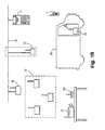
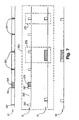
- Fig. 1a illustrates a warehouse environment incorporating a communication network which maintains communication connectivity between the various network devices according to the present invention.
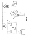
- Fig. 1b illustrates other features of the present invention in the use of a mobile vehicle and an associated microLAN network which is capable of detaching from the main communication network when moving out of range of the main network to perform a service, and reattaching to the main network when moving within range to automatically report on the services rendered.
- Fig. 2 is a diagrammatic illustration of the use of a microLAN supporting roaming data collection by an operator according to the present invention.
- Fig. 3 is a block diagram illustrating the functionality of RF transceivers built in accordance with the present invention.
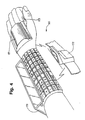
- Fig. 4 is a diagrammatic illustration of an alternate embodiment of the personal microLAN shown in Fig. 2.
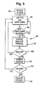
- Fig. 5 is a block diagram illustrating a channel access algorithm used by microLAN slave devices in according to the present invention.
- Fig. 6a is a timing diagram of the protocol used according to the present invention illustrating a typical communication exchange virtually unlimited power resources and a microLAN slave device.
- Fig. 6b is a timing diagram of the protocol used according to the present invention illustrating a typical communication exchange between a microLAN master device having limited power resources and a microLAN slave device.
- Fig. 6c is also a timing diagram of the protocol used which illustrates a scenario wherein the microLAN master device fails to service microLAN slave devices.
- Fig. 7 is a timing diagram illustrating the microLAN master device's servicing of both the high powered main communication network and the low powered microLAN subnetwork, with a single or plural radio transceivers, in accordance with the present invention.
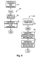
- Figs. 8 and 9 are block diagrams illustrating additional power saving features according to the present invention wherein ranging and battery parameters are used to optimally select the appropriate data rate and power level of subsequent transmissions.
-
- Fig. 1a illustrates a warehouse environment incorporating a communication network which maintains communication connectivity between the various network devices according to the present invention. Specifically, a worker utilizes a
computer terminal 7 and acode reader 9 to collect data such as identifying numbers or codes on warehoused goods, such as thebox 10. As the numbers and codes are collected, they are forwarded through the network to ahost computer 11 for storage and cross-referencing. In addition, thehost computer 11 may, for example, the collected numbers or codes back through the network for display on theterminal 7 or for printing on aprinter 13. Similarly, the collected may be printed from thecomputer terminal 7 directly to theprinter 13. Other exemplary communication pathways supported by the present invention include messages exchanged between thecomputer terminal 7 and other computer terminals (not shown) or thehost computer 11. - Many of the devices found in the illustrative network are battery powered and therefore must conservatively utilize their radio transceivers. For example, the hand-held
computer terminal 7 receives its power from either an enclosed battery or a forklift battery (not shown) via a docking station within theforklift 14. Similarly, thecode reader 9 operates on portable battery power as may theprinter 13. The arrangement of the communication network, communication protocols used, and data rate and power level adjustments help to optimize battery conservation without substantially degrading network performance. - The overall communication network of the present invention is arranged into two functional groups: 1) a main communication network; and 2) a microLAN network. The main communication network in the illustrated warehouse embodiment includes a hard-wired
backbone LAN 19 andbase stations host computer 11 and any other non-mobile network device located in the vicinity of thebackbone LAN 19 can be directly attached to thebackbone LAN 19. However, mobile devices and remotely located devices must maintain connectivity to thebackbone LAN 19 throughstation 15, or through a multi-hop network of base stations such as is illustrated by thebase stations base stations base stations 17 may be necessary. Otherwise, thebackbone LAN 19 must be extended to connect all of thebase stations 17 directly to provide sufficient radio coverage. Through the main communication network, relatively stable, long range wireless and hard-wired communication is maintained. - Network devices that are mobile or remote (i.e., cannot be directly connected to the backbone LAN 19) are fitted with RF transceivers. To guarantee that such a network device will be able to directly communicate with at least one of the
base stations base stations base stations printer 13,modem 23, andcode reader 9 with theterminal 7 provide a justification for a microLAN configuration. in a dock with the sole assignment of printing out forms based on the code information gathered from boxes delivered to the dock. In such an example, only when theforklift 14 enters the dock area should theprinter 13 begin printing the collected code information. Within the dock area, communicating via thebase stations printer 13 is fitted with a low power microLAN transceiver for short range communication directly to thecomputer terminal 7 in theforklift 14. Thecomputer terminal 7 is also fitted with a transceiver capable of direct, low power communication with theprinter 13. Thus, when within microLAN radio range of theprinter 13, thecomputer terminal 7 transmits the code information at a relatively low power level to theprinter 13. While in range (whether printing or not), thecomputer terminal 7 andprinter 13 together participate in a low power, microLAN network. - In the previous example, no communication was necessary between the microLAN devices and the main network. However, other microLAN configurations require at least some access to the main network. For example, because of battery constraints, the
code reader 9 is also fitted with a microLAN transceiver. Whenever thecode reader 9 is used, collected code signals and counterpart information are not directly exchanged with thehost computer 11 via the main network. Instead, in the illustrated example, thecomputer terminal 7 is configured to be able to communicate not only within the network. This is accomplished by fitting thecomputer terminal 7 with a transceiver(s) capable of communicating on both networks (see discussion related to Fig. 3 below). Thus, to reach thehost computer 11, thecode reader 9 first transmits to thecomputer terminal 7 via the microLAN, i.e., through the microLAN transceivers in each device. Upon receipt of the data, thecomputer terminal 7 relays the information to one of thebase stations host 11. Communication from thehost 11 to thecode reader 9 is accomplished via the same pathway. - It is also possible for any two devices in the microLAN network to communicate to each other. For example, the
modem 23 could receive data and directly transmit it to theprinter 13 for printing. Similarly, thecode reader 9 might choose to directly communicate code signals to other network devices via themodem 23. - In an alternate configuration, a
microLAN base station 21 is provided which may be directly connected to the backbone LAN 19 (as shown) or indirectly connected via thebase stations microLAN base station 21 is positioned in the vicinity of a other microLAN network devices and thereafter becomes a participant. Thus, microLAN communication flowing to or from the main communication network avoids high power radio transmissions altogether. However, it can be appreciated that a stationary microLAN base station may not always be an option when all of the microLAN participants are mobile. In such cases, a high power transmission to reach the main communication network may be required. microLAN, the participating devices ("microLAN devices") need not all possess the transceiver capability to reach the main communication network. However, at least one microLAN device needs to have that capability to maintain overall network connectivity. - Fig. 1b illustrates other features of the present invention in the use of a mobile vehicle and an associated microLAN network which is capable of detaching from the main communication network when moving out of range of the main network to perform a service, and reattaching to the main network when moving within range to automatically report on the services rendered. In particular, like the
forklift 14 of Fig. 1a, adelivery truck 33 provides a focal point for microLAN access. Within thetruck 33, astorage terminal 31 is docked so as to draw power from thetruck 33's battery supply. Thestorage terminal 31 is configured with a microLAN transceiver. Similarly, acomputer terminal 7 also configured as a microLAN device may either be docked or ported. Because of greater battery access and because of the amount of data to transfer, thestorage terminal 31 is also configured to communicate with the main communication network. - Prior to making a delivery, the truck enters a docking area for loading. As goods are loaded into the truck, the driver enters information regarding each loaded good into the
storage terminal 31 via either theterminal 7 or the code reader 9 (Fig. 1a) using the microLAN network communications. This loading might also be accomplished automatically as theforklift 14 comes into range of thedelivery truck 31, joins the microLAN network, and transmits the relation to Fig 1a. In addition, as information regarding a good is received and stored, the storage device might also request further information regarding any or all of the goods via the microLAN's link to thehost computer 11 through the main communication network. Specifically, themicroLAN base station 21 if located on the dock could provide a direct low power microLAN connection to thebackbone LAN 19 and to thehost computer 11. Otherwise, because of the normal data flow pathway and because of its greatest access to available power, thestorage terminal 31 is configured with a transceiver capable of communicating with the main communication network via thebase stations storage device 31 communicates via the microLAN to theprinter 13 to generate a printout of information relating to the loaded goods. In addition, the information is transmitted via the microLAN to themodem 23 for relay to a given destination site. Upon reaching the destination, thestorage terminal 31 detects and participates in the microLAN of the delivery site dock. As goods specific goods are unloaded, they are scanned for delivery verification, preventing delivery of unwanted goods. The driver is also informed if goods that should have been delivered are still in the truck. As this process takes place, a report might also be generated via a microLAN printer on the destination dock for signature. Similarly, a microLAN modem on the destination dock might relay the delivery information back to thehost computer 11 for billing information. - Similarly, if the
truck 33 is used for in the morning with the addresses and directions of the service destinations, technical manuals, and service notes which have been selectively downloaded from the host computer via the main network and microLAN to thestorage terminal 31. Upon pulling out of range of the microLAN network in the dock, thestorage terminal 31 and thecomputer terminal 7 automatically form an independent, detached microLAN. At each service address, the driver collects information using theterminal 7 either as the data is collected if within microLAN transmission range of thestorage terminal 31, or as soon as theterminal 7 comes within range. Through the detached microLAN network such information is available on the computer terminal. Upon returning to the dock, as soon as the independent microLAN formed between thestorage terminal 31 and thecomputer terminal 7 come within microLAN range of the microLAN devices on the dock, the detached microLAN automatically merges with the dock's microLAN (becomes "attached"), and thestorage terminal 31 automatically transfers the service information to thehost computer 11 which uses the information for billing and in formulating the service destinations which will be automatically downloaded the next day. - Fig. 2 is a diagrammatic illustration of another embodiment using a microLAN to supporting roaming data collection by an operator according to the present invention. As an
operator 61 roams the warehouse floor he carries with him a microLAN comprising theterminal 7,code reader 9 and aportable printer 58. The operator collect information regarding goods, such as thebox 10, with thecode reader 9 and theterminal 7. If the power resources also communicate with the main communication network. Specifically, corresponding information to the code data must be retrieved from thehost computer 11, collected code information and retrieved corresponding information needs to be displayed on theterminal 7, and, after viewing for verification, the information needs to be printed on theprinter 58. Because of this data flow requirement, thecomputer terminal 7 is selected as the microLAN device which must also carry the responsibility of communicating with the main communication network. - If during collection, the operator decides to power down the
computer terminal 7 because it is not needed, the microLAN network becomes detached from the main communication network. Although it might be possible for the detached microLAN to function, all communication with thehost computer 11 through the main communication network is placed in a queue awaiting reattachment. As soon as the detached microLAN comes within range of an attached microLAN device, i.e., a device attached to the main network, the queued communications are relayed to the host. - To avoid detachment when the
terminal 7 is powered down, thecode reader 9 may be designated as a backup to theterminal 7 for performing the higher power communication to the main communication network. As described in more detail below in reference to Fig. 6c regarding the idle sense protocol, whenever thecode reader 9 determines that theterminal 7 has stopped providing access to the main communication network, thecode reader 9 will take over the role if it is next in line to thecomputer terminal 7 is powered up, it monitors the microLAN channel, requests and regains from thecode reader 9 the role of providing an interface with the main computer network. This, however, does not restrict thecode reader 9 from accessing the main computer network although thereader 9 may choose to use thecomputer terminal 7 for power conservation reasons. - In addition, if the
computer terminal 7 reaches a predetermined low battery threshold level, theterminal 7 will attempt to pass the burden of providing main network access to other microLAN backup devices. If no backup device exists in the current microLAN, thecomputer terminal 7 may refuse all high power transmissions to the main communication network. Alternatively, thecomputer terminal 7 may either refuse predetermined select types of requests, or prompt the operator before performing any transmission to the main network. However, thecomputer terminal 7 may still listen to the communications from the main communication network and inform microLAN members of waiting messages. - Fig. 3 is a block diagram illustrating the functionality of RF transceivers built in accordance with the present invention. Although preferably plugging into PCMCIA slots of the computer terminals and peripherals, the
transceiver 110 may also be built-in or externally attached via available serial, parallel or ethernet connectors for example. Although the transceivers used by potential microLAN master devices may vary from those used by microLAN slave devices (as detailed below), they all contain the illustrated functional - In particular, the
transceiver 110 contains aradio unit 112 which attaches to an attachedantenna 113. Theradio unit 112 used in microLAN slave devices need only provide reliable low power transmissions, and are designed to conserve cost, weight and size. Potential microLAN master devices not only require the ability to communicate with microLAN slave devices, but also require higher power radios to also communicate with the main network. Thus, potential microLAN master devices and other non-microLAN slave devices might contain two radio units 112 (or two transceivers 110) -- one serving the main network and the other serving the microLAN network -- else only contain a single radio unit to service both networks. - In embodiments where cost and additional weight is not an issue, a dual radio unit configuration for potential microLAN master devices provides several advantages. For example, simultaneous transceiver operation is possible by choosing a different operating band for each radio. In such embodiments, a 2.4GHz radio is included for main network communication while a 27MHz radio supports the microLAN network. MicroLAN slave devices receive only the 27MHz radio, while the non-potential microLAN participants from the main network are fitted with only the 2.4GHz radios. Potential microLAN master devices receive both radios. The low power 27 MHz microLAN radio is capable of reliably transferring information at a range of approximately 40 to 100 feet asynchronously at 19.2K BPS. An additional benefit of using the 27 MHz frequency is that it is an unlicensed frequency band. The 2.4GHz radio provides with other main network devices. Many different frequency choices could also be made such as the 900MHz band, etc.
- In embodiments where cost and additional weight are at issue, a single radio unit configuration is used for potential microLAN master devices. Specifically, in such embodiments, a dual mode 2.4GHz radio supports both the microLAN and main networks. In a microLAN mode, the 2.4GHz radio operates at a low power level (sub-milliwatt) to support microLAN communication at relatively close distances (20-30 feet). In a high power (up to 1 Watt) or main mode, the 2.4GHz radio provides relatively long distance communication connectivity with the main network. Although all network devices might be fitted with such a dual mode radio, only microLAN master devices use both modes. MicroLAN slave devices would only use the low power mode while all other main network devices would use only the high power mode. Because of this, to save cost, microLAN slave devices are fitted with a single mode radio operating in the microLAN mode. Non-microLAN participants are also fitted with a single mode (main mode) radio unit for cost savings.
- Connected between the
radio unit 112 and aninterface 110, amicroprocessor 120 controls the information flow between through thetransceiver 110. Specifically, theinterface 115 connects thetransceiver 110 to a selected computer terminal, a peripheral device or other network device. Manydifferent interfaces 115 are used and the choice will depend upon the connection port of the device to which thetransceiver 110 will be attached. Virtually any type oftransceiver 110 of the present invention. Common industry interface standards include RS-232, RS-422, RS-485, 10BASE2 Ethernet, 10BASE5 Ethernet, 10BASE-T Ethernet, fiber optics, IBM 4/16 Token Ring, V.11, V.24, V.35, Apple Localtalk and telephone interfaces. In addition, via theinterface 115, themicroprocessor 120 maintains a radio independent, interface protocol with the attached network device, isolating the attached device from the variations in radios being used. - The
microprocessor 120 also controls theradio unit 112 to accommodate communication with the either the main network (for main mode radios), the microLAN (for microLAN radios), or both (for dual mode radios). More specifically, in a main mode transceiver, themicroprocessor 120 utilizes a main protocol to communicate with the main network. Similarly, in a microLAN mode transceiver, themicroprocessor 120 operates pursuant to a microLAN protocol to communicate in the microLAN network. In the dual mode transceiver, themicroprocessor 120 manages the use of and potential conflicts between both the main and microLAN protocols. Detail regarding the main and microLAN protocols can be found in reference to Figs. 6-9 below. - In addition, as directed by the corresponding communication protocol, the
microprocessor 120 controls the power consumption of theradio 112, itself and theinterface 115 for power conservation. This is accomplished in two ways. First, the microLAN and main protocols are designed to provide for a low power mode or sleep mode during periods when no communication involving the subject transmitter is desired as described below in are designed to adapt in both data rate and transmission power based on power supply (i.e., battery) parameters and range information as described in reference to Figs. 8-9. - In order to insure that the proper device is receiving the information transmitted, each device is assigned a unique address. Specifically, the
transceiver 110 can either have a unique address of its own or can use the unique address of the device to which it is attached. The unique address of the transceiver can either be one selected by the operator or system designer or one which is permanently assigned at the factory such as an IEEE address. Theaddress 121 of theparticular transceiver 110 is stored with themicroprocessor 120. - In the illustrated embodiments of Figs. 1-2, the microLAN master device is shown as being either a microLAN base station or a mobile or portable computer terminal. From a data flow viewpoint in considering the fastest access through the network, such choices for the microLAN master devices appear optimal. However, any microLAN device might be assigned the role of the master, even those that do not seem to provide an optimal data flow pathway but may provide for optimal battery usage. For example, in the personal microLAN network of Fig. 2, because of the support from the
belt 59, the printer might contain the greatest battery capacity of the personal microLAN devices. As such, the printer might be designated the microLAN master device and be fitted with either a dual mode radio or two radios as master devices require. The printer, or other microLAN slave devices, might also be fitted with such recruired radios to serve only as a microLAN actual microLAN master, i.e., the hand-held terminal 7 (Fig. 2), drops below a preset threshold, the backup master takes over. - Fig. 4 is a drawing which illustrates an embodiment of the personal microLAN shown in Fig. 2 which designates a printer as the microLAN master device. Specifically, in a
personal microLAN network 165, acomputer terminal 170 is strapped to the forearm of the operator. Acode reader 171 straps to the back of the hand of the user and is triggered by pressing abutton 173 with the thumb. Because of their relatively low battery energy, thecomputer terminal 170 andcode reader 171 are designated microLAN slave devices and each contain a microLAN transceiver having a broadcast range of two meters or less. Because of its greater battery energy, theprinter 172 contains a dual mode radio and is designated the microLAN master device. - Fig. 5 is a block diagram illustrating a channel access algorithm used by microLAN slave devices in according to the present invention. At a
block 181, when a slave device has a message to send, it waits for an idle sense message to be received from the microLAN master device at ablock 183. When an idle sense message is received, the slave device executes a back-off protocol at ablock 187 by in an attempt to avoid collisions with other slave devices waiting to transmit. Basically, instead of permitting every slave device from repeatedly transmitting immediately after an idle sense message is received, each waiting slave is required to first wait for a pseudo-random time period before attempting a transmission. The pseudo-random back-off time period is generated ablock 189, the channel is sensed to determine whether it is clear for transmission. If not, a branch is made back to theblock 183 to attempt a transmission upon receipt of the next idle sense message. If the channel is still clear, at ablock 191, a relatively small "request to send" type packet is transmitted indicating the desire to send a message. If no responsive "clear to send" type message is received from the master device, the slave device assumes that a collision occurred at ablock 193 and branches back to theblock 183 to try again. If the "clear to send" message is received, the slave device transmits the message at ablock 195. - Several alternate channel access strategies have been developed for carrier sense multiple access (CSMA) systems and include 1-persistent, non-persistent and p-persistent. Such strategies or variations thereof could easily be adapted to work with the present invention.
- Fig. 6a is a timing diagram of the protocol used according to the present invention illustrating a typical communication exchange between a microLAN master device having virtually unlimited power resources and a microLAN slave device.
Time line 201 represents communication activity by the microLAN master device whiletime line 203 represents the corresponding activity by the microLAN slave device. The master periodically transmits anidle sense message 205 indicating that it is available for communication or that it has data for transmission to a slave device. Because the master has virtually unlimited power resources, it "stays awake" for theentire time period 207 between theidle sense messages 205. In other words, the master does not enter a power - The slave device uses a binding protocol (discussed below with regard to Fig. 6c) to synchronize to the master device so that the slave may enter a power conserving mode and still monitor the idle sense messages of the master to determine if the master requires servicing. For example, referring to Fig. 6a, the slave device monitors an idle sense message of the master during a
time period 209, determines that no servicing is required, and enters a power conserving mode during thetime period 211. The slave then activates during atime period 213 to monitor the next idle sense message of the master. Again, the slave determines that no servicing is required and enters a power conserving mode during atime period 215. When the slave activates again during atime period 217 to monitor the next idle sense message, it determines from a "request to send" type message from the master that the master has data for transmission to the slave. The slave responds by sending a "clear to send" type message during thetime period 217 and stays activated in order to receive transmission of the data. The master is thus able to transmit the data to the slave during atime period 219. Once the data is received by the slave at the end of thetime period 221, the slave again enters a power conserving mode during atime period 223 and activates again during thetime period 225 to monitor the next idle sense message. - Alternatively, the slave may have data for transfer to the master. If so, the slave indicates as such to the master by transmitting a message during the
time period 217 and then executes a backoff algorithm to determine how The slave determines from the backoff algorithm that it must wait thetime period 227 before transmitting the data during thetime period 221. The slave devices use the backoff algorithm in an attempt to avoid the collision of data with that from other slave devices which are also trying to communicate with the master. The backoff algorithm is discussed more fully above in reference to Fig. 5. - The idle sense messages of the master may also aid in scheduling communication between two slave devices. For example, if a first slave device has data for transfer to a second slave device, the first slave sends a message to the master during the
time period 209 requesting communication with the second slave. The master then broadcasts the request during the next idle sense message. Because the second slave is monitoring the idle sense message, the second slave receives the request and stays activated at the end of the idle sense message in order to receive the communication. Likewise, because the first slave is also monitoring the idle sense message, it too receives the request and stays activated during thetime period 215 to send the communication. - Fig. 6b is a timing diagram of the protocol used according to the present invention illustrating a typical communication exchange between a microLAN master having limited power resources and a microLAN slave device. This exchange is similar to that illustrated in Fig. 6a except that, because it has limited power resources, the master enters a power conserving mode. Before transmitting an idle sense message, the master listens to determine if the channel is idle. If the channel is idle, the then waits a
time period 231 to determine if any devices desire communication. If no communication is desired, the master enters a power conserving mode during atime period 233 before activating again to listen to the channel. If the channel is not idle, the master does not send the idle sense message and enters a power saving mode for atime period 235 before activating again to listen to the channel. - Communication between the master and slave devices is the same as that discussed above in reference to Fig 6a except that, after sending or receiving data during the
time period 219, the master device enters a power conserving mode during thetime period 237. - Fig. 6c is also a timing diagram of the protocol used which illustrates a scenario wherein the microLAN master device fails to service microLAN slave devices. The master device periodically sends an
idle sense message 205, waits atime period 231, and enters a power conserving mode during atime period 233 as discussed above in reference to Fig 6b. Similarly, the slave device monitors the idle sense messages duringtime periods time periods time period 241, the slave unsuccessfully attempts to monitor an idle sense message. The slave then goes to sleep for atime period 243 and activates to attempt to monitor a next idle sense message during atime period 245, but is again unsuccessful. binding protocol to attempt to regain synchronization with the master. While two time periods (241 and 245) are shown, the slave may initiate such a protocol after any number of unsuccessful attempts to locate an idle sense message. With this protocol, the slave stays active for atime period 247, which is equal to the time period from one idle sense message to the next, in an attempt to locate a next idle sense message. If the slave is again unsuccessful, it may stay active until it locates an idle sense message from the master, or, if power consumption is a concern, the slave may enter a power conserving mode at the end of thetime period 247 and activate at a later time to monitor for an idle sense message. - In the event the master device remains outside the range of the slave devices in the microLAN network for a period long enough such that communication is hindered, one of the slave devices may take over the functionality of the master device. Such a situation is useful when the slave devices need to communicate with each other in the absence of the master. Preferably, such a backup device has the ability to communicate with devices on the main communication network. If the original master returns, it listens to the channel to determine idle sense messages from the backup, indicates to the backup that it has returned and then begins idle sense transmissions when it reestablishes dominance over the microLAN network.
- Fig. 7 is a timing diagram illustrating the microLAN master device's servicing of both the high powered main communication network and the low powered microLAN subnetwork, with a single present invention.
Block 251 represents typical communication activity of the master device. Line 253 illustrates the master's communication with a base station on the main communication network while line 255 illustrates the master's communication with a slave device on the microLAN network. Lines 257 and 259 illustrate corresponding communication by the base station and slave device, respectively. - The base station periodically broadcasts
HELLO messages 261 indicating that it is available for communication. The master device monitors the HELLO messages during atime period 263, and, upon determining that the base does not need servicing, enters a power conserving mode during a time period 265. The master then activates for a time period to monitor the next HELLO message from the base. If the master has data to send to the base, it transmits the data during atime period 271. Likewise, if the base has data to send to the master, the base transmits the data during atime period 269. Once the data is received or sent by the master, it may again enter a power conserving mode. While HELLO message protocol is discussed, a number of communication protocols may be used for communication between the base and the master device. As may be appreciated, the microLAN master device acts as a slave to base stations in the main communication network. - Generally, the communication exchange between the master and the slave is similar to that described above in reference to Fig. 6b.
Block 273, however, illustrates a situation where the master encounters a communication conflict, i.e., it has data to send to or receive from the slave on the subnetwork at the HELLO messages from the base. If the master has two radio transceivers, the master can service both networks. If, however, the master only has one radio transceiver, the master chooses to service one network based on network priority considerations. For example, inblock 273, it may be desirable to service the slave because of the presence of data rather than monitor the main network for HELLO messages from the base. On the other hand, inblock 275, it may be more desirable to monitor the main network for HELLO messages rather than transmit an idle sense message on the subnetwork. - Figs. 8 and 9 are block diagrams illustrating additional power saving features according to the present invention, wherein ranging and battery parameters are used to optimally select the appropriate data rate and power level for subsequent transmissions. Specifically, even though network devices such as the
computer terminal 7 in Figs. 1-2 have the capability of performing high power transmissions, because of battery power concerns, the such devices are configured to utilize minimum transmission energy. For example if By adjusting either the power level and the data rate based . Adjustments are made based on ranging information and on battery parameters. Similarly, within the microLAN network, even though lower power transceivers are used, battery conservation issues also justify the use such data rate and power adjustments. This process is described in more detail below in reference to Figs. 8 and 9. - More specifically, Fig. 8 is a block diagram which illustrates a
protocol 301 used by a destination microLAN device and a microLAN device to adjust the data rate and possibly the power level for future transmission between the two devices. At ablock 311, upon receiving a transmission from a source device, the destination device identifies a range value at ablock 313. In a low cost embodiment, the range value is identified by considering the received signal strength indications (RSSI) of the incoming transmission. Although RSSI circuitry might be placed in all microLAN radios, the added expense may require that only microLAN master devices receive the circuitry. This would mean that only microLAN master devices would perform the function of the destination device. Other ranging values might also be calculated using more expensive techniques such as adding GPS (Global Position Service) circuitry to both radios. In such an embodiment, the range value transmitted at theblock 313 would consist of the GPS position of the destination microLAN device. Finally, after identifying the range value at theblock 313, the destination device subsequently transmits the range value to the slave device from which the transmission was received. - Upon receipt of the range value from the destination device at a
block 321, the source microLAN device evaluates its battery parameters to identify a subsequent data rate for transmission at ablock 323. If range value indicates that the destination microLAN device is very near, the source microLAN device selects a faster data rate. When the range value indicates a distant master, the source device selects a slower rate. In this way, even without adjusting the power level, the total energy dissipated can be controlled to utilize transmission. However, if constraints are placed on the maximum or minimum data rates, the transmission power may also need to be modified. For example, to further minimize the complexity associated with a fully random range of data rate values, a standard range and set of several data rates may be used. Under such a scenario, a transmission power adjustment might also need to supplement the data rate adjustment. Similarly, any adjustment of power must take into consideration maximum and minimum operable levels. Data rate adjustment may supplement such limitations. Any attempted modification of the power and data rate might take into consideration any available battery parameters such as those that might indicate a normal or current battery capacity, the drain on the battery under normal conditions and during transmission, or the fact that the battery is currently being charged. The latter parameter proves to be very significant in that when the battery is being charged, the microLAN slave device has access to a much greater power source for transmission, which may justify the highest power transmission and possibly the slowest data rate under certain circumstances. - Finally, at a
block 325, an indication of the identified data rate is transmitted back to the destination device so that future transmissions may take place at the newly selected rate. The indication of data rate may be explicit in that a message is transmitted designating the specific rate. Alternately, the data rate may be transferee implicitly in that the new rate is chose and used by the source, requiring the destination to adapt to the change. This might also be done using a - Fig. 9 illustrates an alternate embodiment for carrying out the data rate and possibly power level adjustment. At a
block 351 upon binding and possibly periodically, the source microLAN device sends an indication of its current battery parameters to the destination microLAN device. This indication may be each of the parameters or may be an averaged indication of all of the parameters together. At ablock 355, upon receipt, thedestination microLAN device 355 stores the battery parameters (or indication). Finally, at ablock 358, upon receiving a transmission from the source device, based on range determinations and the stored battery parameters, the destination terminal identifies the subsequent data rate (and possibly power level). Thereafter, the new data rate and power level are communicated to the source device for either explicitly or implicitly for future transmissions. - Moreover, it will be apparent to one skilled in the art having read the foregoing that various modifications and variations of this communication system according to the present invention are possible and is intended to include all those which are covered by the appended claims.
Claims (7)
- An RF local area network comprising:a first network device, the first network device transmitting using battery power;a second network device;means within the second network device for identifying a range value indicative of the distance between the first and second network devices;the second network device responsive to the identifying means by transmitting the range value to the first network device; andthe first network device, upon receipt of the range value, identifying an appropriate data rate for subsequent transmission to the second network device.
- An RF local area network comprising:a first network device;a battery power supply disposed for powering the first network device, the battery power supply having battery parameter information;a second network device;means within the second network device for identifying a range value indicative of the distance between the first and second network devices;the second network device responsive to the identifying means by sending the range value to the first network device;means within the first network device for identifying the battery parameter information; andthe first network device, based on the received range value and battery parameter information, identifying an appropriate data rate and power level for subsequent transmission to the second network device.
- An RF local area network comprising:a first network device;a battery power supply disposed for powering the first network device, the battery power supply having battery parameter information;means within the second network device for identifying a range value indicative of the distance between the first and second network devices;the first network device transmitting battery parameter information to the second network device; andthe second network device, based on the range value and received battery parameter information, indicating to the first network device an appropriate rate andpower level for subsequent data transmission.
- A communication system comprising:a first radio network operating using a first communication protocol;a second radio network operating using a second communication protocol;a mobile network device having a single radio unit capable of participating in both the first and second radio networks;the mobile network device participating as a slave device to the first radio network pursuant to the first communication protocol while participating as a master device to the second radio network pursuant to the second communication protocol; andthe mobile network device resolving conflicts between the first and second communication protocols.
- A communication system comprising:a main radio network;a radio subnetwork;a mobile network device having a first radio transceiver for communicating with the main radio network and a second radio transceiver for communicating with the radio subnetwork;the mobile network device participating as a slave device to the main radio network while participating as a master device to the radio subnetwork.
- A communication system comprising:a first radio network operating using a first communication protocol; a second communication protocol;a mobile network device having a single radio unit capable of participating in both the first and second radio networks;the mobile network device participating as a slave device to the first radio network pursuant to the first communication protocol while participating as a master device to the second radio network pursuant to the second communication protocol; andthe mobile network device entering a state of low power consumption when not communicating with either the first or the second radio network.
- A communication system comprising:a first radio network comprising a first plurality of network devices;a second radio network comprising a second plurality of network devices;a mobile network device configured to participate as a member of both the first andsecond pluralities of network devices;when within range of one of the second plurality of network devices, the mobile network device participates as a master device in the second radio network; andwhen within range of one of the first plurality of network devices, the mobile network device participates as a slave device in the first radio network;the second plurality of network devices entering a state of low power consumption when communication with the mobile network device is not available.
Applications Claiming Priority (5)
| Application Number | Priority Date | Filing Date | Title |
|---|---|---|---|
| US99769392A | 1992-12-23 | 1992-12-23 | |
| US27140 | 1993-03-05 | ||
| US08/027,140 US5602854A (en) | 1991-05-13 | 1993-03-05 | Wireless personal local area network utilizing removable radio frequency modules with digital interfaces and idle sense communication protocol |
| EP94905966A EP0681762B1 (en) | 1992-12-23 | 1993-12-23 | Wireless personal local area network |
| US997693 | 2001-11-30 |
Related Parent Applications (2)
| Application Number | Title | Priority Date | Filing Date |
|---|---|---|---|
| EP94905966A Division EP0681762B1 (en) | 1992-12-23 | 1993-12-23 | Wireless personal local area network |
| EP94905966.1 Division | 1994-07-07 |
Publications (3)
| Publication Number | Publication Date |
|---|---|
| EP1585269A2 true EP1585269A2 (en) | 2005-10-12 |
| EP1585269A3 EP1585269A3 (en) | 2012-03-28 |
| EP1585269B1 EP1585269B1 (en) | 2015-06-03 |
Family
ID=26702116
Family Applications (2)
| Application Number | Title | Priority Date | Filing Date |
|---|---|---|---|
| EP05014083.9A Expired - Lifetime EP1585269B1 (en) | 1992-12-23 | 1993-12-23 | Wireless personal local area network |
| EP94905966A Expired - Lifetime EP0681762B1 (en) | 1992-12-23 | 1993-12-23 | Wireless personal local area network |
Family Applications After (1)
| Application Number | Title | Priority Date | Filing Date |
|---|---|---|---|
| EP94905966A Expired - Lifetime EP0681762B1 (en) | 1992-12-23 | 1993-12-23 | Wireless personal local area network |
Country Status (7)
| Country | Link |
|---|---|
| US (1) | US5602854A (en) |
| EP (2) | EP1585269B1 (en) |
| AT (1) | ATE343263T1 (en) |
| AU (1) | AU696841B2 (en) |
| CA (1) | CA2152598C (en) |
| DE (1) | DE69334077T2 (en) |
| WO (1) | WO1994015413A1 (en) |
Families Citing this family (76)
| Publication number | Priority date | Publication date | Assignee | Title |
|---|---|---|---|---|
| US5602854A (en) * | 1991-05-13 | 1997-02-11 | Norand Corporation | Wireless personal local area network utilizing removable radio frequency modules with digital interfaces and idle sense communication protocol |
| US6614768B1 (en) | 1989-04-28 | 2003-09-02 | Broadcom Corporation | Enhanced mobility and address resolution in a wireless premises based network |
| US6359872B1 (en) * | 1997-10-28 | 2002-03-19 | Intermec Ip Corp. | Wireless personal local area network |
| US6654378B1 (en) * | 1992-03-18 | 2003-11-25 | Broadcom Corp. | Transaction control system including portable data terminal and mobile customer service station |
| US6749122B1 (en) * | 1990-05-25 | 2004-06-15 | Broadcom Corporation | Multi-level hierarchial radio-frequency system communication system |
| US6970434B1 (en) * | 1995-06-07 | 2005-11-29 | Broadcom Corporation | Hierarchical communication system providing intelligent data, program and processing migration |
| EP0634853A3 (en) * | 1993-07-05 | 1996-12-11 | Victor Company Of Japan | Wireless communication network system. |
| GB2282906B (en) | 1993-10-13 | 1996-11-06 | Dataquill Ltd | Data enty systems |
| ATE169136T1 (en) * | 1993-10-26 | 1998-08-15 | Radisson Hotels Internationals | SYSTEM AND METHOD FOR REWARDING PERSONS WHO MAKE TRAVEL RESERVATIONS |
| US7885242B2 (en) | 1993-12-23 | 2011-02-08 | Broadcom Corp. | Enhanced mobility and address resolution in a wireless premises based network |
| US5724655A (en) * | 1994-04-12 | 1998-03-03 | Motorola, Inc. | Method and apparatus for operating a communication unit consisting of multiple devices |
| US6092117A (en) * | 1994-09-02 | 2000-07-18 | Packard Bell Nec | System and method for automatically reconnecting a wireless interface device to a host computer |
| US5974558A (en) * | 1994-09-02 | 1999-10-26 | Packard Bell Nec | Resume on pen contact |
| US6262719B1 (en) | 1994-09-02 | 2001-07-17 | Packard Bell Nec, Inc. | Mouse emulation with a passive pen |
| US5867106A (en) * | 1994-09-02 | 1999-02-02 | Packard Bell Nec | Password switch to override remote control |
| US6292181B1 (en) | 1994-09-02 | 2001-09-18 | Nec Corporation | Structure and method for controlling a host computer using a remote hand-held interface device |
| US5636213A (en) * | 1994-12-28 | 1997-06-03 | Motorola | Method, transceiver, and system for providing wireless communication compatible with 10BASE-T Ethernet |
| DE19514223B4 (en) * | 1995-04-15 | 2005-06-23 | Claas Kgaa Mbh | Method for optimizing the use of agricultural machinery |
| US5621417A (en) * | 1995-06-07 | 1997-04-15 | General Electric Company | Method and mechanism for reduction of within-train reported data |
| US5682139A (en) * | 1995-06-07 | 1997-10-28 | General Electric Company | Railcar location using mutter networks and locomotive transmitter during transit |
| US5691980A (en) * | 1995-06-07 | 1997-11-25 | General Electric Company | Local communication network for power reduction and enhanced reliability in a multiple node tracking system |
| IL118283A (en) * | 1995-06-07 | 2000-06-29 | Gen Electric | Tracking system for assets subject to movement |
| US5873070A (en) * | 1995-06-07 | 1999-02-16 | Norand Corporation | Data collection system |
| US5608412A (en) * | 1995-06-07 | 1997-03-04 | General Electric Company | Protocol and mechanism for mutter mode communication for stationary master tracking unit |
| US5588005A (en) * | 1995-06-07 | 1996-12-24 | General Electric Company | Protocol and mechanism for primary and mutter mode communication for asset tracking |
| US5686888A (en) * | 1995-06-07 | 1997-11-11 | General Electric Company | Use of mutter mode in asset tracking for gathering data from cargo sensors |
| GB2343597B (en) * | 1995-08-15 | 2000-07-26 | Motorola Inc | Multimedia access system |
| US6279153B1 (en) | 1995-10-16 | 2001-08-21 | Nec Corporation | Multi-user flash ROM update |
| US6148344A (en) * | 1995-10-16 | 2000-11-14 | Nec Corporation | System and method for enabling an IPX driver to accommodate multiple LAN adapters |
| US6005533A (en) * | 1995-10-16 | 1999-12-21 | Packard Bell Nec | Remote occlusion region |
| US7512671B1 (en) * | 1995-10-16 | 2009-03-31 | Nec Corporation | Computer system for enabling a wireless interface device to selectively establish a communication link with a user selectable remote computer |
| US6724372B1 (en) | 1995-10-16 | 2004-04-20 | Nec Corporation | Ink trails on a wireless remote interface tablet and wireless remote ink field object |
| US6108727A (en) * | 1995-10-16 | 2000-08-22 | Packard Bell Nec | System having wireless interface device for storing compressed predetermined program files received from a remote host and communicating with the remote host via wireless link |
| US5990875A (en) * | 1995-10-16 | 1999-11-23 | Packard Bell Nec | Double pen up event |
| US6664982B1 (en) | 1995-10-16 | 2003-12-16 | Nec Corporation | Multi-user on-screen keyboard |
| US5996082A (en) * | 1995-10-16 | 1999-11-30 | Packard Bell Nec | System and method for delaying a wake-up signal |
| US6126327A (en) * | 1995-10-16 | 2000-10-03 | Packard Bell Nec | Radio flash update |
| GB9603582D0 (en) | 1996-02-20 | 1996-04-17 | Hewlett Packard Co | Method of accessing service resource items that are for use in a telecommunications system |
| US5774870A (en) * | 1995-12-14 | 1998-06-30 | Netcentives, Inc. | Fully integrated, on-line interactive frequency and award redemption program |
| US5838798A (en) * | 1996-02-07 | 1998-11-17 | Ncr Corporation | Restaurant transaction processing system and method |
| US6069890A (en) | 1996-06-26 | 2000-05-30 | Bell Atlantic Network Services, Inc. | Internet telephone service |
| US6154445A (en) * | 1996-04-18 | 2000-11-28 | Bell Atlantic Network Services, Inc. | Telephony communication via varied redundant networks |
| DE19624019B4 (en) * | 1996-06-17 | 2005-03-03 | Claas Kgaa Mbh | Apparatus and method for mobile communication of work machines |
| US6069896A (en) * | 1996-10-15 | 2000-05-30 | Motorola, Inc. | Capability addressable network and method therefor |
| US5940400A (en) * | 1996-11-06 | 1999-08-17 | Motorola, Inc. | Method, device, wireless transceiver and computer for providing collision detection in wireless carrier sense multiple access systems |
| US5960327A (en) * | 1996-12-06 | 1999-09-28 | Motorola | Method for a transceiver to select a channel |
| US6078582A (en) | 1996-12-18 | 2000-06-20 | Bell Atlantic Network Services, Inc. | Internet long distance telephone service |
| GB9720856D0 (en) * | 1997-10-01 | 1997-12-03 | Olivetti Telemedia Spa | Mobile networking |
| US6137869A (en) | 1997-09-16 | 2000-10-24 | Bell Atlantic Network Services, Inc. | Network session management |
| US6574216B1 (en) | 1997-03-11 | 2003-06-03 | Verizon Services Corp. | Packet data network voice call quality monitoring |
| US6292479B1 (en) | 1997-03-19 | 2001-09-18 | Bell Atlantic Network Services, Inc. | Transport of caller identification information through diverse communication networks |
| US6870827B1 (en) | 1997-03-19 | 2005-03-22 | Verizon Services Corp. | Voice call alternative routing through PSTN and internet networks |
| US5903259A (en) * | 1997-03-31 | 1999-05-11 | Compaq Computer Corporation | Method and apparatus for mapping remote control buttons onto keyboard stroke combinations |
| US6128484A (en) * | 1997-10-07 | 2000-10-03 | International Business Machines Corporation | Wireless transceivers for remotely controlling a computer |
| US6163538A (en) | 1997-10-09 | 2000-12-19 | Monarch Marketing Systems, Inc. | Wireless serial port transceiver |
| FI112897B (en) | 1998-03-03 | 2004-01-30 | Nokia Corp | Method of communication network and communication device |
| GB2341753A (en) * | 1998-09-17 | 2000-03-22 | Nokia Mobile Phones Ltd | RF interface for portable communication terminal |
| DE69940996D1 (en) * | 1999-04-01 | 2009-07-30 | Lucent Technologies Inc | Improved data rate control for wireless communication |
| EP1050793A3 (en) * | 1999-05-03 | 2004-09-08 | Symbol Technologies, Inc. | Wearable communication system |
| US7289478B1 (en) * | 1999-07-30 | 2007-10-30 | At&T Corp. | Method and apparatus for a fixed wireless broadband access and wireless LAN integration |
| GB2366131A (en) * | 2000-01-28 | 2002-02-27 | Mitel Telecom Ltd | A short reach communication network |
| US6990548B1 (en) * | 2000-06-15 | 2006-01-24 | Hewlett-Packard Development Company, L.P. | Methods and arrangements for configuring a printer over a wireless communication link using a wireless communication device |
| US7200130B2 (en) | 2001-02-13 | 2007-04-03 | Nokia Corporation | Short range RF network configuration |
| US6745253B2 (en) * | 2001-03-24 | 2004-06-01 | Hewlett-Packard Development Company, Lp. | System and method for locating and using a peripheral device |
| GB2375013A (en) * | 2001-04-27 | 2002-10-30 | Ericsson Telefon Ab L M | Communicating connectivity information in a frequency hopping piconet |
| US7266429B2 (en) * | 2001-04-30 | 2007-09-04 | General Electric Company | Digitization of field engineering work processes at a gas turbine power plant through the use of portable computing devices operable in an on-site wireless local area network |
| US20020188511A1 (en) * | 2001-05-14 | 2002-12-12 | Trilegiant Loyalty Solutions | Interactive online point redemption system |
| US20020173324A1 (en) * | 2001-05-18 | 2002-11-21 | Huba Horompoly | Method for protocol-specific information management for wireless devices |
| US6990316B2 (en) | 2001-06-26 | 2006-01-24 | Nokia Corporation | Short range RF network configuration |
| JP4168714B2 (en) * | 2001-12-17 | 2008-10-22 | ソニー株式会社 | COMMUNICATION DEVICE AND METHOD, RECORDING MEDIUM, AND PROGRAM |
| US20030157959A1 (en) * | 2002-01-11 | 2003-08-21 | Jakke Makela | Method, system, apparatus and computer program product for portable networking of multi-user applications |
| US7516244B2 (en) | 2003-07-02 | 2009-04-07 | Caterpillar Inc. | Systems and methods for providing server operations in a work machine |
| US8238538B2 (en) | 2009-05-28 | 2012-08-07 | Comcast Cable Communications, Llc | Stateful home phone service |
| GB2494717A (en) | 2011-09-13 | 2013-03-20 | Bae Systems Plc | Portable wireless network |
| GB2497555A (en) * | 2011-12-14 | 2013-06-19 | Renesas Mobile Corp | Selecting a network configuration based on determined power consumption |
| CN112349002B (en) * | 2020-10-20 | 2022-09-02 | 苏州市东挺河智能科技发展有限公司 | Energy-saving magnetic lock with buffering function |
Citations (3)
| Publication number | Priority date | Publication date | Assignee | Title |
|---|---|---|---|---|
| US4606044A (en) * | 1983-03-09 | 1986-08-12 | Ricoh Company, Ltd. | Adjusting data transmission rate based on received signal quality |
| EP0353759A2 (en) * | 1988-08-04 | 1990-02-07 | Norand Corporation | Mobile radio data communication system and method |
| US5003619A (en) * | 1989-01-31 | 1991-03-26 | Motorola, Inc. | Method and apparatus for adjusting the power of a transmitter |
Family Cites Families (10)
| Publication number | Priority date | Publication date | Assignee | Title |
|---|---|---|---|---|
| US4539706A (en) * | 1983-02-03 | 1985-09-03 | General Electric Company | Mobile vehicular repeater system which provides up-link acknowledgement signal to portable transceiver at end of transceiver transmission |
| CA1290020C (en) * | 1987-02-09 | 1991-10-01 | Steven Messenger | Wireless local area network |
| US5023824A (en) * | 1987-10-02 | 1991-06-11 | Norand Corporation | Hand-held computerized data collection terminal with indented hand grip and conforming battery drawer |
| US5602854A (en) * | 1991-05-13 | 1997-02-11 | Norand Corporation | Wireless personal local area network utilizing removable radio frequency modules with digital interfaces and idle sense communication protocol |
| CA1340400C (en) * | 1989-01-31 | 1999-02-16 | Philip Miller | Vehicle data system |
| US5029183A (en) * | 1989-06-29 | 1991-07-02 | Symbol Technologies, Inc. | Packet data communication network |
| GB9019490D0 (en) * | 1990-09-06 | 1990-10-24 | Ncr Co | Transmission control for a wireless local area network station |
| US5179721A (en) * | 1990-11-05 | 1993-01-12 | Motorola Inc. | Method for inter operation of a cellular communication system and a trunking communication system |
| US5220678A (en) * | 1991-08-12 | 1993-06-15 | Motorola, Inc. | Method and apparatus for adjusting the power of a transmitter |
| US5241542A (en) * | 1991-08-23 | 1993-08-31 | International Business Machines Corporation | Battery efficient operation of scheduled access protocol |
-
1993
- 1993-03-05 US US08/027,140 patent/US5602854A/en not_active Expired - Lifetime
- 1993-12-23 AT AT94905966T patent/ATE343263T1/en not_active IP Right Cessation
- 1993-12-23 EP EP05014083.9A patent/EP1585269B1/en not_active Expired - Lifetime
- 1993-12-23 CA CA002152598A patent/CA2152598C/en not_active Expired - Fee Related
- 1993-12-23 EP EP94905966A patent/EP0681762B1/en not_active Expired - Lifetime
- 1993-12-23 WO PCT/US1993/012628 patent/WO1994015413A1/en active IP Right Grant
- 1993-12-23 DE DE69334077T patent/DE69334077T2/en not_active Expired - Lifetime
- 1993-12-23 AU AU59869/94A patent/AU696841B2/en not_active Ceased
Patent Citations (3)
| Publication number | Priority date | Publication date | Assignee | Title |
|---|---|---|---|---|
| US4606044A (en) * | 1983-03-09 | 1986-08-12 | Ricoh Company, Ltd. | Adjusting data transmission rate based on received signal quality |
| EP0353759A2 (en) * | 1988-08-04 | 1990-02-07 | Norand Corporation | Mobile radio data communication system and method |
| US5003619A (en) * | 1989-01-31 | 1991-03-26 | Motorola, Inc. | Method and apparatus for adjusting the power of a transmitter |
Also Published As
| Publication number | Publication date |
|---|---|
| US5602854A (en) | 1997-02-11 |
| CA2152598A1 (en) | 1994-07-07 |
| EP1585269A3 (en) | 2012-03-28 |
| EP1585269B1 (en) | 2015-06-03 |
| WO1994015413A1 (en) | 1994-07-07 |
| AU5986994A (en) | 1994-07-19 |
| EP0681762A4 (en) | 2000-03-01 |
| EP0681762A1 (en) | 1995-11-15 |
| CA2152598C (en) | 2005-05-24 |
| AU696841B2 (en) | 1998-09-17 |
| ATE343263T1 (en) | 2006-11-15 |
| EP0681762B1 (en) | 2006-10-18 |
| DE69334077D1 (en) | 2006-11-30 |
| DE69334077T2 (en) | 2007-05-10 |
Similar Documents
| Publication | Publication Date | Title |
|---|---|---|
| EP1585269B1 (en) | Wireless personal local area network | |
| US5682379A (en) | Wireless personal local area network | |
| US6359872B1 (en) | Wireless personal local area network | |
| US5696903A (en) | Hierarchical communications system using microlink, data rate switching, frequency hopping and vehicular local area networking | |
| US5657317A (en) | Hierarchical communication system using premises, peripheral and vehicular local area networking | |
| US5949776A (en) | Hierarchical communication system using premises, peripheral and vehicular local area networking | |
| US5574979A (en) | Periodic interference avoidance in a wireless radio frequency communication system | |
| US6654378B1 (en) | Transaction control system including portable data terminal and mobile customer service station | |
| US6614768B1 (en) | Enhanced mobility and address resolution in a wireless premises based network | |
| US8170627B2 (en) | Wireless communications system having reduced noise mode operation capability | |
| US6665536B1 (en) | Local area network having multiple channel wireless access | |
| EP0752763B1 (en) | Multi-level radio-frequency communication system | |
| WO1994027382A1 (en) | Premises, peripheral and vehicular local area networking | |
| US7885242B2 (en) | Enhanced mobility and address resolution in a wireless premises based network | |
| EP0721701B1 (en) | A method of power conservation | |
| CA2476866A1 (en) | Wireless personal local area networks and power saving mechanisms therefor | |
| CA2162722A1 (en) | Premises, peripheral and vehicular local area networking | |
| EP1067814A1 (en) | Mobile station and communication system with variable reception cycle | |
| KR101258297B1 (en) | Apparatus and Method for controlling wireless LAN module | |
| GB0118673D0 (en) | Communications systems |
Legal Events
| Date | Code | Title | Description |
|---|---|---|---|
| PUAI | Public reference made under article 153(3) epc to a published international application that has entered the european phase |
Free format text: ORIGINAL CODE: 0009012 |
|
| AC | Divisional application: reference to earlier application |
Ref document number: 0681762 Country of ref document: EP Kind code of ref document: P |
|
| AK | Designated contracting states |
Kind code of ref document: A2 Designated state(s): AT BE CH DE DK ES FR GB GR IE IT LI LU MC NL PT SE |
|
| RAP1 | Party data changed (applicant data changed or rights of an application transferred) |
Owner name: BROADCOM CORPORATION |
|
| RIC1 | Information provided on ipc code assigned before grant |
Ipc: H04L 12/40 20060101AFI20111103BHEP Ipc: H04W 28/22 20090101ALI20111103BHEP |
|
| PUAL | Search report despatched |
Free format text: ORIGINAL CODE: 0009013 |
|
| AK | Designated contracting states |
Kind code of ref document: A3 Designated state(s): AT BE CH DE DK ES FR GB GR IE IT LI LU MC NL PT SE |
|
| RIC1 | Information provided on ipc code assigned before grant |
Ipc: H04W 28/22 20090101ALI20120222BHEP Ipc: H04L 12/40 20060101AFI20120222BHEP |
|
| 17P | Request for examination filed |
Effective date: 20120928 |
|
| AKX | Designation fees paid |
Designated state(s): DE FR GB |
|
| 17Q | First examination report despatched |
Effective date: 20121126 |
|
| REG | Reference to a national code |
Ref country code: DE Ref legal event code: R071 Ref document number: 69334382 Country of ref document: DE |
|
| GRAP | Despatch of communication of intention to grant a patent |
Free format text: ORIGINAL CODE: EPIDOSNIGR1 |
|
| INTG | Intention to grant announced |
Effective date: 20150113 |
|
| GRAS | Grant fee paid |
Free format text: ORIGINAL CODE: EPIDOSNIGR3 |
|
| GRAA | (expected) grant |
Free format text: ORIGINAL CODE: 0009210 |
|
| AC | Divisional application: reference to earlier application |
Ref document number: 0681762 Country of ref document: EP Kind code of ref document: P |
|
| AK | Designated contracting states |
Kind code of ref document: B1 Designated state(s): DE FR GB |
|
| REG | Reference to a national code |
Ref country code: GB Ref legal event code: FG4D |
|
| REG | Reference to a national code |
Ref country code: GB Ref legal event code: PE20 Expiry date: 20131222 |
|
| REG | Reference to a national code |
Ref country code: DE Ref legal event code: R096 Ref document number: 69334382 Country of ref document: DE |
|
| REG | Reference to a national code |
Ref country code: DE Ref legal event code: R097 Ref document number: 69334382 Country of ref document: DE |
|
| PLBE | No opposition filed within time limit |
Free format text: ORIGINAL CODE: 0009261 |
|
| STAA | Information on the status of an ep patent application or granted ep patent |
Free format text: STATUS: NO OPPOSITION FILED WITHIN TIME LIMIT |
|
| 26N | No opposition filed |
Effective date: 20160304 |