FIELD OF THE INVENTION
The present invention relates to a compound, and to a
solid electrolyte, a proton conductor, a membrane electrode
assembly and a fuel cell comprising the compound.
DESCRIPTION OF THE RELATED ART
The important functions of the electrolytic membrane
(proton conductor membrane) for solid polymer fuel cells are
to physically insulate the fuel (e.g., hydrogen, aqueous
methanol solution) fed to the anode, catalyst electrode from
the oxidizing gas (e.g., oxygen) fed to the cathode, to
electrically insulate the anode from the cathode, and to
transmit the proton having been formed on the anode to the
cathode. To fulfill these functions, the electrolytic
membrane must have some mechanical strength and good proton
conductivity.
In the electrolytic membrane for solid polymer fuel cells,
generally used is a sulfonic acid group-having perfluorocarbon
polymer such as typically Nafion®. The electrolytic membrane
of the type has good ionic conductivity and has relatively high
mechanical strength, but has some problems to be solved such
as those mentioned below. Concretely, in the electrolytic
membrane, water and the sulfonic acid group form cluster
channels, and protons move in the cluster channels via water
therein. Therefore, the ionic conductivity of the membrane
significantly depends on the water content thereof that is
associated with the humidity in the service environment in which
the cells are driven. For poisoning reduction in the catalyst
electrode with CO and for activation of the catalyst electrode
therein, solid polymer fuel cells are preferably driven at a
temperature falling within a range of from 100 to 150°C.
However, within such a middle-temperature range, the water
content of the electrolytic membrane in the cells lowers with
the reduction in the ionic conductivity thereof, and it causes
a problem in that the expected cell characteristics could not
be obtained. In addition, the softening point of the
electrolytic membrane is around 120°C and when the cells are
driven at a temperature around it, then still another problem
with it is that the mechanical strength of the electrolytic
membrane is unsatisfactory. On the other hand, when the
electrolytic membrane of the type is used in direct methanol
fuel cells (DMFC), then it causes still other problems such as
those mentioned below. Naturally, the barrier ability of the
membrane against the fuel methanol is not good as the membrane
readily absorbs water, and therefore methanol having been fed
to the anode penetrates through the electrolytic membrane to
reach the cathode. Owing to it, the cell output power lowers,
and this is referred to as a methanol-crossover phenomenon. For
practical use of DMFC, this is one important problem to be
solved.
Given that situation, there is a growing tendency for the
development of other proton-conductive materials
substitutable for Nafion®, and some hopeful electrolytic
materials have been proposed. For example, proposed is an
organic-inorganic nanohybrid proton-conductive material that
is obtained through sol-gel reaction of a precursor, organic
silicon compound in the presence of a proton acid. See Japanese
Patent 3,103,888, German Patent DE 10061920A1, Electrochimica
Acta, 1988, Vol. 43, Nos. 10-11, p. 1301, and Solid State Ionics,
2001, No. 145, p. 1277. The organic-inorganic composite and
hybrid proton-conductive material of the type comprise an
inorganic component and an organic component, in which the
inorganic component comprises silicic acid and proton acid and
serves as a proton-conductive site and the organic component
serves to make the material flexible. When the inorganic
component is increased so as to increase the proton conductivity
of the membranes formed of the material, then the mechanical
strength of the membranes lowers. On the other hand, however,
when the organic component is increased so as to increase the
flexibility of the membranes, then the proton conductivity of
the membranes lowers. Therefore, the material that satisfies
the two characteristics are difficult to obtain. Regarding the
methanol perviousness of the material, which is an important
characteristic of the material tor use in DMFC, any satisfactory
description is not found in the related literature.
SUMMARY OF THE INVENTION
Objects of the present invention are to provide a compound
for ion exchanger and proton conductors capable of being used
for ion-exchange membranes and proton-conductive membranes
which have a high ionic conductivity and are not so much troubled
by methanol-crossover through them and which are therefore
favorable for DMFC, and to provide a solid electrolyte and a
proton conductor comprising the compound, a membrane electrode
assembly comprising the proton conductor, and a high-power fuel
cell comprising the membrane electrode assembly.
Taking the above-mentioned objects into consideration,
we, the present inventors have assiduously studied and, as a
result, have found that, when a sol-gel reaction precursor of
an aryl group-containing organosilicon compound that has a
mesogen and an electron-donating group (e. g., a hydroxyl group
or an alkoxy group, more preferably a hydroxyl group) in the
molecule is subjected to sulfonation followed by sol-gel
reaction or to sol-gel reaction followed by sulfonation, then
the organic molecular chain and the proton-donating
group-bonded silicon-oxygen matrix moiety that is to be a
proton-conductive channel undergo nano-level phase separation,
and preferably the organic molecular chain is oriented
horizontally to the membrane face, and, as a result, an
organic-inorganic nano-hybrid material may be constructed in
which the proton-conductive channel runs to cross the membrane
face. In addition, we have further found that the membrane thus
obtained is flexible and has high mechanical strength. On the
basis of these findings, we have reached the present invention.
In particular, an organic-inorganic hybrid proton conductor
that is obtained through sol-gel reaction of a sulfonic acid
compound obtained through sulfonation of at least one
organosilicon compound of formulae (I) and (II) is especially
favorable for the objects of the invention. Through
observation thereof with a polarizing microscope, we have
clarified that the proton conductor of the type forms aggregates
of oriented organic molecular chains therein. In this case,
the proton-donating group-bonded silicon-oxygen network that
is to be a proton-conductive channel is formed inevitably in
the direction perpendicular to the orientation direction of the
organic molecule aggregates. Accordingly, when the
orientation direction of the organic molecular chains is
controlled to the horizontal direction relative to the membrane
face, then the proton-conductive channels are constructed to
cross the membrane.
Concretely, the objects of the invention can be attained
by the following constitution:
In the proton conductor of the invention, the sulfo group
is covalent-bonded to the silicon/oxygen three-dimensional
crosslinked matrix, and, in addition, the compound for the
conductor has a mesogen in the molecule thereof. Therefore,
in this, at least a part of the organic molecular chains are
oriented to form aggregates. Accordingly, the proton
conductor has a high ionic conductivity at room temperature and
is resistant to an aqueous methanol solution, and the methanol
crossover through it is therefore reduced. When the proton
conductor is used in direct methanol fuel cells, then it may
prevent voltage reduction and enables higher output as compared
with conventional proton conductors.
BRIEF DESCRIPTION OF THE DRAWINGS
Fig. 1 is a schematic cross-sectional view showing the
constitution of a catalyst membrane electrode assembly that
uses the proton conductor of the invention.
Fig. 2 is a schematic cross-sectional view showing one
example of the constitution of the fuel cell of the invention.
Fig. 3 is a schematic view showing a stainless cell
employed in determination of methanol perviousness through the
membrane of the invention.
DETAILED DESCRIPTION OF THE INVENTION
The invention is described in detail hereinunder. In
this description, the numerical range expressed by the wording
"a number to another number" means the range that falls between
the former number indicating the lowermost limit of the range
and the latter number indicating the uppermost limit thereof ,
[1] Organosilicon Compound and Sulfonic Acid Group-Having
Precursor:
The proton conductor of the invention has a structure in
which organic molecular chains containing a sulfo group and a
mesogen group are covalent-bonded to the silicon/oxygen
three-dimensional crosslinked matrix thereof, and this can be
formed through sol-gel reaction and sulfonation of a precursor,
organosilicon compound represented by the following formula (I)
or (II), which has an arylene group containing an
electron-donating group, preferably a hydroxyl group, and a
mesogen group for promoting the orientation of organic
molecular chains. The precursor for forming it is described
in detail hereinunder.
[1-1] Mesogen-containing Organosilicon Compound Precursor:
The proton conductor of the invention can be formed
through sol-gel reaction and sulfonation of a precursor,
organosilicon compound of the following formula (I) or (II) .
In these formulae (I) and (II), A1 and A2 each
independently represent a mesogen-containing organic group; R1
and R3 each independently represent a hydrogen atom, an alkyl
group, an aryl group or a silyl group; R2 and R4 each
independently represent an alkyl group, an aryl group or a
heterocyclic group; m1 and m2 each independently indicate an
integer of from 1 to 3; L1 and L2 each independently represent
a single bond, an alkylene group, -O-, -CO-, or a divalent
linking group of a combination of any of these groups; Ar1 and
Ar2 each independently represent an arylene or heteroarylene
group having at least one electron-donating group; Y1 represents
a polymerizable group capable of forming a carbon-carbon bond
or a carbon-oxygen bond through polymerization; n11 and n2 each
independently indicate an integer of from 1 to 8; n12 indicates
an integer of from 1 to 4; s1 and s2 each independently indicate
an integer of 1 or 2.
In the mesogen-containing organosilicon compound of
formulae (I) and (II), the alkyl group for R1 to R4 is preferably
a straight, branched or cyclic alkyl group (e.g., alkyl group
having from 1 to 20 carbon atoms, such as methyl group, ethyl
group, isopropyl group, n-butyl group, 2-ethylhexyl group,
n-decyl group, cyclopropyl group, cyclohexyl group,
cyclododecyl group) ; the aryl group for R1 to R4 is preferably
a substituted or unsubstituted phenyl or naphthyl group having
from 6 to 20 carbon atoms. Preferred examples of the
heterocyclic group for R2 and R4 are a substituted or
unsubstituted heterocyclic 6-membered ring (e.g., pyridyl
group, morpholino group), and a substituted or unsubstituted
heterocyclic 5-membered ring (e.g., furyl group, thiophene
group). Preferred examples of the silyl group for R1 and R3 are
a silyl group substituted by three alkyl groups selected from
those having from 1 to 10 carbon atoms (e.g., trimethylsilyl
group, triethylsilyl group, triisopropylsilyl group), and a
polysiloxane group (e.g., -(Me2SiO)nH (n = 10 to 100).
Preferably, m1 and/or m2 are 2 or 3, more preferably m1 and/or
m2 are 3. When m1, m2, 3-m1, 3-m2, n11, n12 or n2 is 2 or more,
then the parenthesized units may be the same or different.
Similarly, when s1, s2 and n12 are 2 or more, then the
parenthesized units may be the same or different.
The above-mentioned substituent may be further
substituted with any of the following substituents.
A1 and A2 each independently represent a
mesogen-containing organic group. Preferred examples of the
mesogen group are described in Dietrich Demus & Horst Zaschke,
Flussige Kristalle in Tablelen II, 1984, pp. 7-18. Those of
the following formula (III) are especially preferred:
(III)
[Q1-Y2-Q2]m3
In formula (III), Q1 represents a single bond, a
monovalent group, or an (n12 + 1) -valent linking group; Q2
represents a single bond, an (n11 + 1) -valent group or an (n2
+1) -valent linking group. n11, n12 and n2 are the same numbers
as n11, n12 and n2 in formulae (I) and (II) . Of Q1 and Q2, Q2
bonds to the Si containing group.
More preferably, Q1 is a divalent linking group or a single
bond. Also more preferably, Q2 is a divalent linking group or
a single bond.
The divalent linking group for Q1 and Q2 is preferably
-CH=CH-, -CH=N-, -N=N-, -N (O) =N-, -COO-, -COS-, -CONH-, -COCH2-,
-CH2CH2-, -OCH2-, -CH2NH-, -CH2-, -CO-, -O-, -S-, -NH-, - (CH2)(1 to 3)-,
-CH=CH-COO-, -CH=CH-CO-, -(C≡C)-, arylene, or their
combination, more preferably -CH2-, -CO-, -O-, -CH=CH-, -CH=N-,
-N=N-, arylene, or their combination, even more preferably,
-CH2-, -CO-, -O-, arylene, or their combination. When these
are combined, the same linking groups, or different linking
groups or both of the two may be combined in any desired manner,
and the number of the groups to be combined is not specifically
defined.
Examples of the monovalent group for Q1 are the
above-mentioned divalent linking groups of which one end is
terminated with a hydrogen atom or a halogen atom, and a hydrogen
atom and a halogen atom. The halogen atom is preferably a
fluorine atom. m3 is an integer of from 1 to 3. When m3 is
2 or more, then the parenthesized units may be the same or
different.
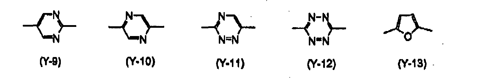
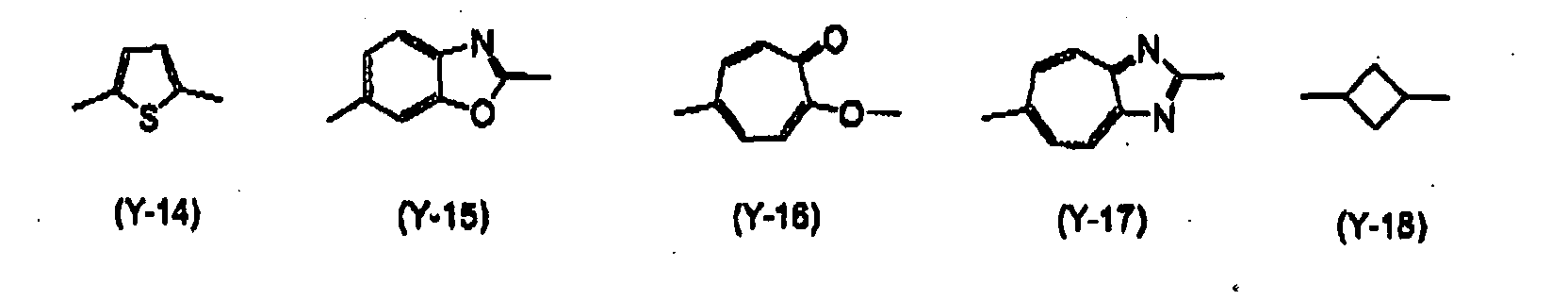
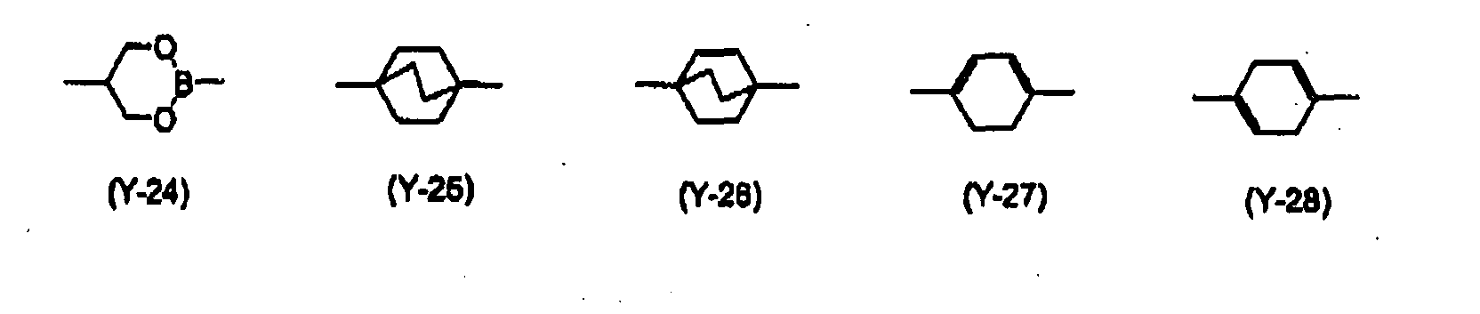
Y2 represents a divalent, 4-, 5-, 6- or 7-membered ring
substituent, or a condensed ring substituent comprising them.
Y2 is preferably a 6-membered aromatic group, a 4- to 6-membered
saturated or unsaturated alicyclic group, a 5- or 6-membered
heterocyclic group, or a condensed ring comprising them. For
the condensed ring, the above-mentioned rings for Y2 are
preferably condensed to form a disc-like structure, for example,
triphenylene.
Preferred examples of Y
1 are substituents of the following
(Y-1) to (Y-30), and their combinations. Of those substituents,
more preferred are (Y-1), (Y-2), (Y-18), (Y-19), (Y-21), (Y-22)
and (Y-29); and more preferred are (Y-1), (Y-2), (Y-21) and
(Y-29).
Preferably, the organosilicon compound contains an alkyl
or alkylene group having at least 5 carbon atoms along with the
mesogen, for enhancing the molecular orientation of the
compound. Preferably, the alkyl or alkylene group has from 5
to 25 carbon atoms, more preferably from 6 to 18 carbon atoms.
The alkyl or alkylene group in the organosilicon compound may
be substituted. Preferred examples of the substituent for the
group are an alkyl group, an aryl group, a heterocyclic group,
an alkoxy group, an acyloxy group, an alkoxycarbonyl group, a
cyano group and a fluoro group, such as those mentioned
hereinabove.
L1 and L2 each independently represent a single bond, an
alkylene group, -O-, -CO-, or a divalent linking group of a
combination of any of these groups, preferably an alkylene group,
more preferably an alkylene group having from 2 to 12 carbon
atoms, even more preferably an alkylene group having from 2 to
8 carbon atoms. Single bond means that Si directly bonds to
Ar1 or Ar2.
Y1 represents a polymerizable group capable of forming
a carbon-carbon bond or a carbon-oxygen bond through
polymerization, including, for example, acryloyl,
methacryloyl, vinyl, ethynyl and alkyleneoxide (e.g.,
ethyleneoxide, trimethyleneoxide) groups. Preferably, it is
an acryloyl, methacryloyl, ethyleneoxide or trimethyleneoxide
group.
Ar1 and Ar2 each independently represent an arylene or
heteroarylene group (hereinafter referred to as
"(hetero)arylene group") substituted with at least one
electron-donating group. The electron-donating group is
preferably a substituent having a Hammett's σp value of at most
-0.15. The Hammett's σp value is described in Chemical Review,
Vol. 91, No. 2 (1991), pp. 165-195. For example, the
substituent includes a methyl group (-0.17), a methoxy group
(-0.27), a hydroxyl group (-0.37), a dimethylamino group
(-0.83) . Of those, preferred are a hydroxyl group and an alkoxy
group (more preferably, methoxy or ethoxy). Even more
preferred is a hydroxyl group. The electron-donating group may
be in any position in Ar1 and Ar2, but is preferably so positioned
that the ortho or para-position is unsubstituted. The
(hetero)arylene group may have any other substituent than the
electron-donating group, still having a position at which the
group is sulfonated. For example, the group may be substituted
with any substituent mentioned above.
In addition, the (hetero) arylene group may be condensed.
In this case, it preferably forms a biryclic group. The arylene
or heteroarylene group having at least one electron-donating
group is, for example, a (hetero)arylene group having from 6
to 24 carbon atoms, more concretely including a
hydroxyphenylene group, a hydroxynaphthylene group, a
methoxyfurandiyl group, a methoxythiophene-diyl group, and a
hydroxypyridine-diyl group.
In formulae (I) and (II), Ar1 or Ar2 may directly bond
to the mesogen group, the alkyl group or the alkenyl group that
constitutes the organic group A1 or A2, or may bond thereto via
a linking group. Preferably, the linking group is an alkylene
group having from 1 to 15 carbon atoms, or a combination of such
an alkylene group and the linking group Q1 or Q2 of the mesogen.
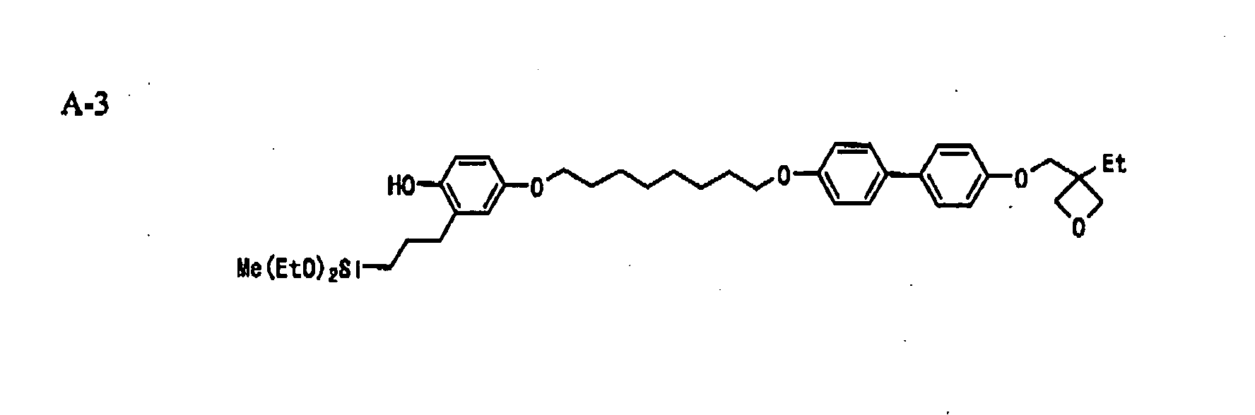
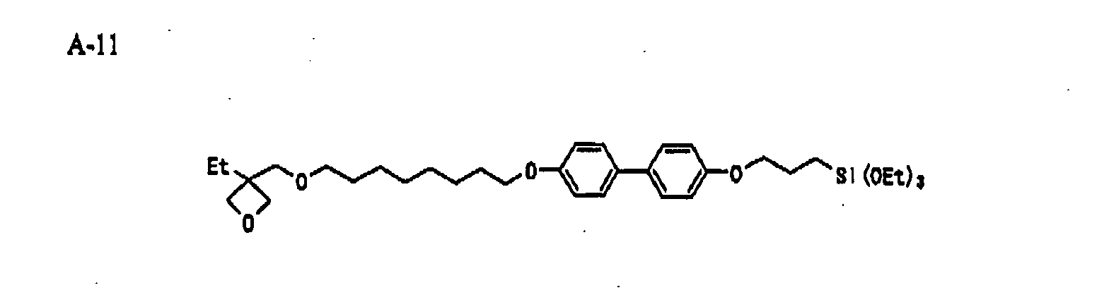
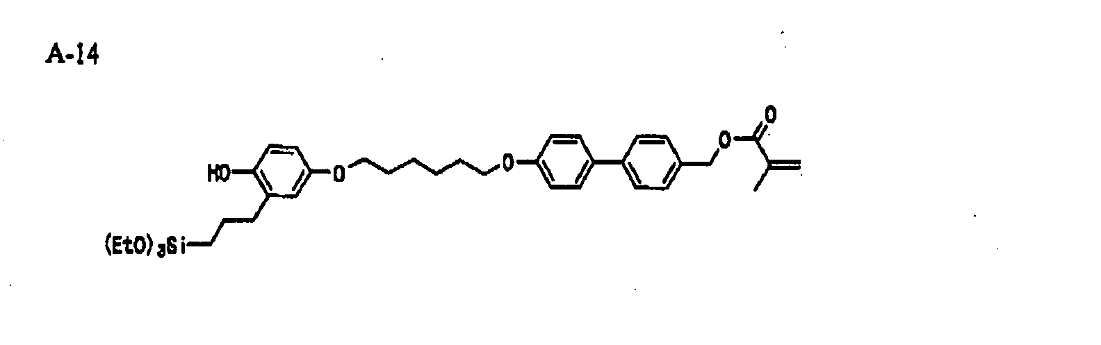
Examples of the mesogen-containing organosilicon
compound of formulae (I) and (II) are mentioned below, to which,
however, the invention should not be limited.
The compound of formula (I) or (II) may be readily
produced through hydrosilylation of a corresponding olefin
compound that contains an arylene group having an
electron-donating group (preferably a hydroxyl group), and a
mesogen. The olefin compound having a hydroxyl
group-containing arylene group may be produced, for example,
through [3.3] sigmatropic rearrangement (Claisen
rearrangement) of an allyl aryl ether in an inorganic solvent
(e.g., decahydronaphthalene, diphenyl ether, dimethylaniline,
diethylaniline) or without solvents. For the hydrosilylation,
for example, employable is the method described in Lecture of
Experimental Chemistry, 4th Edition (by the Chemical Society
of Japan, Maruzen), Vol. 24, p. 125.
Example of Producing Compound (A-1) :
Production of (M-3):
A compound (M-1) (42 g) and a compound (M-2) (51.5 g) were
dissolved in 500 ml of dimethylacetamide, and potassium
carbonate (31.5 g) was added to it. The reaction solution was
stirred at 100°C for 5 hours, then cooled to room temperature,
and poured into water, and the deposited crystal was taken out
through filtration. Thus obtained, the crude crystal was
recrystallized from acetonitrile, and 33 g of (M-3) was
obtained.
Production of (M-6):
A compound (M-4) (15 g) was dissolved in 150 ml of
dimethylacetamide, and potassium carbonate (30 g) and potassium
iodide (18 g) were added to it. Then, (M-5) (15 g) was added
to it. The reaction solution was stirred at 100°C for 5 hours,
cooled to room temperature, and poured into water, and the
deposited crystal was taken out through filtration. Thus
obtained, the crude crystal was recrystallized from hexane, and
17 g of (M-6) was obtained.
Production of (M-7):
Thus obtained, (M-6) (12.5 g) was dissolved in 60 ml of
acetonitrile, and pyridine (13 m-1) was added to it and heated
with stirring under reflux. After the reaction, water was added
to it, and the organic substance was extracted out with ethyl
acetate. The organic phase was dried with sodium sulfate, the
solvent was evaporated away, and the residue was purified
through silica gel column chromatography to obtain (M-7) (10.1
g) .
Production of (M-8) :
Thus obtained, (M-7) (10.1 g) and (M-3) (10.7 g) were
dissolved in 100 ml of dimethylacetamide, and potassium
carbonate (5.2 g) was added to it. The reaction solution was
stirred at 100°C for 5 hours, cooled to room temperature, and
poured into water, and the organic substance was extracted out
with ethyl acetate. The organic phase was dried with sodium
sulfate, the solvent was evaporated away, and the residue was
purified through silica gel column chromatography to obtain
(M-8). (10.0 g).
Production of (M-9):
Thus obtained, (M-8) (10.0 g) was heated in a nitrogen
flow at 200°C. After 5 hours, this was cooled to room
temperature, and the residue was purified through silica gel
column chromatography to obtain 8.3 g of (M-9).
Production of (A-1) :
(M-9) (8.3 g) and triethoxysilane (4.2 g) were dissolved
in 10 ml of toluene, and a solution prepared by dissolving 15
mg of chloroplatinic acid in 0.5 ml of benzonitrile was dropwise
added to it in a nitrogen flow at 80°C. The reaction solution
was reacted at 80°C for 1 hour, and the reaction mixture was
concentrated and purified through silica gel column
chromatography to obtain 4.3 g of (A-1) (colorless viscous
liquid).
Example of Producing Compound (A-10):
Production of (M-10):
A compound (M-1) (3.7 g) and a compound (M-7) (17 g) were
dissolved in 100 ml of dimethylacetamide, and potassium
carbonate (6 g) was added to it. The reaction solution was
stirred at 100°C for 5 hours, then cooled to room temperature,
and poured into water, and the organic substance was extracted
out with ethyl acetate. The organic phase was dried with sodium
sulfate, the solvent was evaporated away, and the residue was
purified through silica gel column chromatography to obtain
(M-10) (10.6 g) .
Production of (M-11) :
In a nitrogen flow, a mixture of (M-10) (10 g) obtained
herein and 10 ml of decahydronaphthalene was heated under reflux.
After 5 hours, this was cooled to room temperature, hexane was
added to the reaction mixture, and the solid was taken out
through filtration. The resulting solid was purified through
silica gel column chromatography to obtain 8.5 g of (M-11) .
Production of (A-10) :
(M-11) (8.5 g) obtained herein and diethoxymethylsilane
(7.0 g) were dissolved in 20 ml of toluene, and a solution
prepared by dissolving 30 mg of chloroplatinic acid in 1 ml of
benzonitrile was dropwise added to it in a nitrogen flow at 80°C.
The reaction solution was reacted at 80°C for 1 hour, and the
reaction mixture was concentrated and purified through silica
gel column chromatography to obtain 4.8 g of (A-10) (colorless
viscous liquid).
[1-2] Introduction of Sulfo Group:
Preferably, a sulfo group is introduced into the proton
conductor of the invention, for which the organosilicon
compound of formula (I) or (II) is reacted with a sulfonating
agent before or after the sol-gel reaction to be mentioned below,
or after the film formation. The method including sol-gel
reaction after sulfonation as referred to herein is meant to
include both a case of sol-gel reaction to be effected just after
sulfonation and a case of sol-gel reaction to be effected after
sulfonation via some operation (reaction or working step).
Similarly, the method including sulfonation after sol-gel
reaction is meant to include both a case of sulfonation to be
effected just after sol-gel reaction and a case of sulfonation
to be effected after sol-gel reaction via some operation
(reaction or working step).
The sulfonating agent acts on the (hetero) arylene group,
Ar1 or Ar2 in formula (I) or (II), directly or via the substituent
of the group, and a sulfo group is thereby introduced into the
compound.
For the sulfonating agent, for example, herein usable are
those described in New Experimental Chemistry Lecture, Vol. 14,
3rd. Ed., Synthesis and Reaction of Organic Compound (edited
by the Chemical Society of Japan). Preferred example of the
sulfonating agent for use herein are sulfuric acid,
chlorosulfonic acid, fuming sulfuric acid, amidosulfuric acid,
sulfur trioxide, sulfur trioxide complexes (e.g., SO3-DMF,
SO3-THF, SO3-dioxane, SO3-pyridine) . More preferred examples
are chlorosulfonic acid and sulfur trioxide complexes; and even
more preferred are sulfur trioxide complexes.
[2] Method for Forming Proton Conductor:
[2-1] Sol-Gel Process:
In the invention, generally employed is a sol-gel process
that includes metal alkoxide hydrolysis, condensation and
drying (optionally firing) to give a solid. For example, herein
employable are the methods described in Patent References 1 and
2 and Non-Patent References 1 and 2. An acid catalyst is
generally used for condensation. However, in the invention,
the precursor after sulfonation described in [1-1] may serve
as an acid catalyst, and the reaction does not require any
additional acid to be added thereto.
One typical method of forming the proton conductor of the
invention includes dissolving a compound of formula (I) or (II)
in a solvent (e.g., DMF, THF, dioxane, methylene chloride,
diethyl ether) and reacting it with a sulfonating agent. After
the sulfonation, this is subjected to alkoxysilyl group
hydrolysis and polycondensation (this is hereinafter referred
to as "sol-gel" reaction). In these reactions, the system may
be heated, if desired. The viscosity of the reaction mixture
(sol) gradually increases, and after the solvent is evaporated
away and the remaining sol is dried, then a solid (gel) is
obtained. While fluid, the sol may be cast into a desired vessel
or applied onto a substrate, and thereafter the solvent is
evaporated away and the remaining sol is dried to give a solid
membrane. For further densifying the silica network formed
therein, the membrane may be optionally heated after dried if
desired. The product obtained by dissolving a compound of
formula (I) or (II) in a solvent followed by subjecting it to
sol-gel reaction may be treated with a sulfonating agent to
thereby introduce a sulfo group into it, and a membrane may be
formed in that manner.
The solvent for the sol-gel reaction is not specifically
defined so far as it dissolves the precursor, organosilicon
compound. For it, however, preferred are carbonate compounds
(e.g., ethylene carbonate, propylene carbonate), heterocyclic
compounds (e.g., 3-methyl-2-oxazolidinone,
N-methylpyrrolidone), cyclic ethers (e.g., dioxane,
tetrahydrofuran), linear ethers (e.g., diethyl ether, ethylene
glycol dialkyl ether, propylene glycol dialkyl ether,
polyethylene glycol dialkyl ether, polypropylene glycol
dialkyl ether), alcohols (e.g., methanol, ethanol, isopropanol,
ethylene glycol monoalkyl ether, propylene glycol monoalkyl
ether, polyethylene glycol monoalkyl ether, polypropylene
glycol monoalkyl ether), polyalcohols (e.g., ethylene glycol,
propylene glycol, polyethylene glycol, polypropylene glycol,
glycerin), nitrile compounds (e.g., acetonitrile,
glutarodinitrile, methoxyacetonitrile, propionitrile,
benzonitrile), esters (e.g., carboxylates, phosphates,
phosphonates), aprotic polar substances (e.g.,
dimethylsulfoxide, sulforane, dimethylformamide,
dimethylacetamide), non-polar solvents (e.g., toluene,
xylene), chlorine-containing solvents (e.g., methylene
chloride, ethylene chloride), water, etc. Above all,
especially preferred are alcohols such as ethanol, isopropanol,
fluoroalcohols; nitrile compounds such as acetonitrile,
glutarodinitrile, methoxyacetonitrile, propionitrile,
benzonitrile; and cyclic ethers such as dioxane,
tetrahydrofuran. One or more of these may be used herein either
singly or as combined. For controlling the drying speed, a
solvent having a boiling point of not lower than 100°C, such
as N-methylpyrrolidone, dimethylacetamide, sulforane or
dioxane, may be added to the above-mentioned solvent. The total
amount of the solvent is preferably from 0.1 to 100 g, more
preferably from 1 to 10 g, per gram of the precursor compound.
For promoting the sol-gel reaction, an acid catalyst may
be used. Preferably, the acid catalyst is an inorganic or
organic proton acid. The inorganic proton acid includes, for
example, hydrochloric acid, sulfuric acid, phosphoric acids
(e.g., H3PO4, H3PO3, H4P2O7, H5P3O10, metaphosphoric acid,
hexafluorophosphoric acid), boric acid, nitric acid,
perchloric acid, tetrafluoroboric acid, hexafluoroarsenic
acid, hydrobromic acid, solid acids (e.g., tungstophosphoric
acid, tungsten-peroxo complex). For the organic proton acid,
for example, usable are low-molecular compounds such as
phosphates (for example, those with from 1 to 30 carbon atoms,
such as methyl phosphate, propyl phosphate, dodecyl phosphate,
phenyl phosphate, dimethyl phosphate, didodecyl phosphate),
phosphites (for example, those with from 1 to 30 carbon atoms,
such as methyl phosphite, dodecyl phosphite, diethyl phosphite,
diisopropyl phosphite, didodecyl phosphite), sulfonic acids
(for example, those with from 1 to 15 carbon atoms, such as
benzenesulfonic acid, toluenesulfonic acid,
hexafluorobenzenesulfonic acid, trifluoromethanesulfonic
acid, dodecylsulfonic acid), carboxylic acids (for example,
those with from 1 to 15 carbon atoms, such as acetic acid,
trifluoroacetic acid, benzoic acid, substituted benzoic acids),
imides (e.g., bis(trifluoromethanesulfonyl)imido acid,
trifluoromethanesulfonyltrifluoroacetamide), phosphonic
acids (for example, those with from 1 to 30 carbon atoms, such
as methylphosphonic acid, ethylphosphonic acid,
phenylphosphonic acid, diphenylphosphonic acid,
1,5-naphthalenebisphosphonic acid); and proton acid
segment-having high-molecular compounds, for example,
perfluorocarbonsulfonic acid polymers such as typically
Nafion®, poly(meth)acrylates having a phosphoric acid group
in side branches (JP-A 2001-114834), and sulfonated,
heat-resiatant aromatic polymers such as sulfonated
polyether-ether ketones (JP-A 6-93111), sulfonated polyether
sulfones (JP-A 10-45913), sulfonated polysulfones (JP-A
9-245818) . Two or more of these may be used herein, as combined.
The reaction temperature in the sol-gel reaction is
associated with the reaction speed, and it may be suitably
determined depending on the reactivity of the precursor to be
reacted and on the type and the amount of the acid used.
Preferably, it falls between -20°C and 150°C, more preferably
between 0°C and 80°C, even more preferably between 20°C and 60°C.
[2-2] Polymerization of Polymerizable Group Y1:
When the polymerizable group Y1 is a carbon-carbon
unsaturated bond-having group, for example, a (meth) acryloyl,
vinyl or ethynyl group, then radical polymerization for
ordinary polymer production may apply to the case. The process
is described in Takayuki Ohtsu & Masaetsu Kinoshita,
Experimental Process for Polymer Production (by Kagaku Dojin),
and Takayuki Ohtsu, Lecture of Polymerization Theory 1, Radical
Polymerization (1) (by Kagaku Dojin).
The radical polymerization includes thermal
polymerization with a thermal polymerization initiator and
photopolymerization with a photopolymerization initiator.
Preferred examples of the thermal polymerization initiator are
azo-type initiators such as 2,2'-azobis(isobutyronitrile),
2,2'-azobis(2,4-dimethylvaleronitrile), dimethyl
2,2'-azobis(2-methylpropionate); and peroxide-type
initiators such as benzoyl peroxide. Preferred examples of the
photopolymerization initiator are α-carbonyl compounds (USP
2,367,661 and 2,367,670), acyloin ethers (USP 244,828),
α-hydrocarbon-substituted aromatic acyloin compounds (USP
2,722,512), polynuclear quinone compounds (USP 3,046,127 and
2,951,758), combinations of triarylimidazole dimer and
p-aminophenyl ketone (USP 35, 493, 676), acridine and phenazine
compounds (JP-A 60-105667, USP 4,239,850), and oxadiazole
compounds (USP 4,212,970).
The polymerization initiator may be added to the reaction
system before the start of the sol-gel reaction in the above
[2-1], or may be added to the reaction product after the sol-gel
reaction and immediately before the application of the reaction
product to substrates. Preferably, the amount of the
polymerization initiator to be added is from 0.01 to 20 % by
mass, more preferably from 0.1 to 10 % by mass relative to the
total amount of the monomers.
When the polymerizable group Y1 is an alkylene oxide group
such as ethylene oxide or trimethylene oxide, then the
polymerization catalyst to be used in the case may be a proton
acid (as in the above [2-1]), or a Lewis acid (preferably, boron
trifluoride (including its ether complex), zinc chloride,
aluminium chloride) . In case where the proton acid used in the
sol-gel reaction serves also as the polymerization catalyst,
then it does not require any additional proton acid specifically
for the polymerization of the polymerizable group Y1. When used,
the polymerization catalyst is preferably added to the reaction
product just before the product is applied to substrates. In
general, the polymerization is promoted in the membrane being
formed on substrates through exposure of the membrane to heat
or light. With that, the molecular orientation in the membrane
is fixed and the membrane strength is thereby enhanced.
[2-3] Combination with Other Silicon Compound:
If desired, two or more precursors described in the above
[1-1] may be mixed for use herein for improving the properties
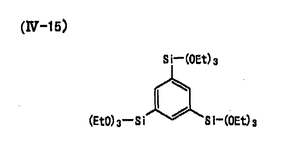
of the membranes formed. Optionally, any other silicon
compound may be further added to these precursors. Examples
of the additional silicon compound are organosilicon compounds
of the following formula (IV), and their polymers.
(IV) (R5)m4 -Si - (OR6) 4-m4
wherein R5 represents a substituted or unsubstituted alkyl, aryl
or heterocyclic group; R6 represents a hydrogen atom, an alkyl
group, an aryl group, or a silyl group; m4 indicates an integer
of from 0 to 4; when m4 or (4-m4) is 2 or more, then R5's or
R6's may be the same or different, and R5's or R6's may bond to
each other to form a ring. The compounds of formula (IV) may
bond to each other at R5 or at the substituent on R5 to form
polymers.
In formula (IV), m4 is preferably from 0 to 2, and R
6 is
preferably an alkyl group. Examples of preferred compounds
where m4 is 0 are tetramethoxysilane (TMOS) and
tetraethoxysilane (TEOS) . Examples of preferred compounds
where m4 is 1 or 2 are mentioned below.
(IV-1) n-C3H7-Sl-(OEt)3
(IV-2) n-C6H13-Si-(OEt)3
(IV-5) (EtO)3-Si-(CH2)8-Si-(OEt)3
(IV-6) Me(EtO)2-Si-(CH2)8-Si-(OEt)2Me
(IV-9) (EtO)3-Si-(CH2)3-NHCOO-(CH2CH2O)3CONH-(CH2)3Si-(OEt)3
When the compound of formula (IV) is combined with the
organosilicon compound precursor, then its amount is preferably
from 1 to 50 mol%, more preferably from 1 to 20 mol% of the
precursor.
[2-4] Addition of Polymer Compound:
The proton conductor of the invention may contain various
polymer compounds for the purpose of (1) enhancing the
mechanical strength of the membrane, and (2) increasing the acid
concentration in the membrane. (1) For enhancing the
mechanical strength of the membrane, preferably added thereto
is a polymer compound having a molecular weight of from 10,000
to 1,000,000 or so and well compatible with the
proton-conductive material of the invention. For example, the
polymer compound includes perfluoropolymer, polystyrene,
polyethylene glycol, polyoxetane, poly(meth)acrylate,
polyether ketone, polyether sulfone and their copolymers.
Preferably, the polymer content of the membrane is from 1 to
30 % by mass. (2) For increasing the acid concentration in the
membrane, preferably used herein are proton acid segment-having
polymer compounds, for example, perfluorocarbonsulfonic acid
polymers such as typically Nafion®, poly (meth) acrylates having
a phosphoric acid group in the side branches, and sulfonated,
heat-resistant aromatic polymers such as sulfonated
polyether-ether ketones, sulfonated polyether sulfones,
sulfonated polysulfones, sulfonated polybenzimidazoles. The
content of the polymer compound in the membrane is preferably
from 1 to 30 % by mass.
The sol-gel reaction of the organosilicon compound
precursor goes on while the organic site of the organosilicon
compound is oriented after the sol-gel reaction mixture that
contains the precursor is applied onto a substrate. To promote
the orientation of the sol-gel composition, various methods may
be employed. For example, supports such as those mentioned
above may be previously oriented. The orientation may be
effected in any ordinary method. Preferably, an orientable
liquid-crystal layer of, for example, various orientable
polyimide films or polyvinylalcohol films is formed on a support,
and rubbed for orientation; or the sol-gel composition applied
on a support is put in a magnetic field or an electric field,
or it is heated.
Regarding the orientation condition of the
organic-inorganic hybrid proton conductor, it is confirmed
through observation with a polarizing microscope that the
membrane is optically anisotropic. The direction in which the
membrane sample is observed may be any one, not specifically
defined. For example, when the sample rotated in a cross-Nicol
condition gives changing dark and light shadows, then it can
be said that the sample is anisotropic. The orientation
condition of the membrane is not specifically defined provided
that the membrane shows anisotropy. When a texture that can
be recognized as a liquid-crystal phase is observed in the
membrane sample, then the phase may be specifically identified.
In this case, the phase may be any of a lyotropic liquid-crystal
phase or a thermotropic liquid-crystal phase. Regarding its
orientation condition, the lyotropic liquid-crystal phase is
preferably a hexagonal phase, a cubic phase, a lamella phase,
a sponge phase or a micelle phase. Especially at room
temperature, preferred is a lamella phase or a sponge phase.
The thermotropic liquid-crystal phase is preferably any of a
nematic phase, a smectic phase, a crystal phase, a columnar
phase and a cholesteric phase. Especially at room temperature,
preferred are a smectic phase and a crystal phase. Also
preferably, these phases may be oriented and fixed in solid.
Anisotropy as referred to herein means that the directional
vector of molecules is not isotropic.
The thickness of the organic-inorganic hybrid proton
conductor that is obtained by peeling it from the support is
preferably from 10 to 500 µm, more preferably from 25 to 100
µm.
[2-5] Method of Film Formation:
The supports to which the sol-gel reaction mixture is
applied in the invention are not specifically defined, and their
preferred examples are glass substrates, metal substrates,
polymer films and reflectors. Examples of the polymer films
are cellulose polymer films of TAC (triacetyl cellulose), ester
polymer films of PET (polyethylene terephthalate) or PEN
(polyethylene naphthalate), fluoropolymer films of PTFE
(polytrifluoroethylene), and polyimide films. Any known
method of, for example, curtain coating, extrusion coating,
roll coating, spin coating, dipping, bar coating, spraying,
slide coating or printing is herein employable for applying the
sol-gel reaction mixture to the supports.
[2-6] Filling to Porous Membrane:
The proton-conductive material of the invention may be
infiltrated into the pores of a porous substrate to form a film.
The sol-gel reaction solution of the invention is applied to
a porous substrate so that it is infiltrated into the pores of
the substrate, or such a porous substrate is dipped in the
sol-gel reaction solution to thereby fill the pores with the
proton-conductive material to form a film. Preferred examples
of such a porous substrate are porous polypropylene, porous
polytetrafluoroethylene, porous crosslinked heat-resistant
polyethylene and porous polyimide films.
[2-7] Addition of Catalyst Metal to Proton Conductor:
An active metal catalyst may be added to the proton
conductor of the invention for promoting the redox reaction of
anode fuel and cathode fuel. The fuel having penetrated into
the proton conductor that contains the catalyst may be well
consumed inside the proton conductor, not reaching any other
electrode, and this is effective for preventing crossover. The
active metal for the catalyst is not specifically defined
provided that it functions as an electrode catalyst. For it,
for example, suitable is platinum or platinum-based alloy.
[3] Fuel cell:
[3-1] Cell structure:
A fuel cell is described, which includes the
organic-inorganic hybrid proton conductor of the invention.
Fig. 1 shows the constitution of a membrane electrode assembly
(hereinafter referred to as "MEA") 10 for fuel cells. The MEA
10 has a proton conductor 11, and an anode 12 and a cathode 13
that are opposite to each other via the conductor 11.
The anode 12 and the cathode 13 include a porous
conductive sheet (e.g., carbon paper) 12a, 13a, and a catalyst
layer 12b, 13b. The catalyst layer 12b, 13b is formed of a
dispersion of carbon particles (e.g., ketjen black, acetylene
black, carbon nanotubes) that carry a catalyst metal such as
platinum particles thereon, in a proton-conductive material
(e. g., Nafion) . For airtightly adhering the catalyst layer 12b,
13b to the proton conductor 11, generally employed is a method
of hot-pressing the porous conductive sheet 12a, 13a coated with
the catalyst layer 12b, 13b, against the proton conductor 11
(preferably at 120 to 130°C under 2 to 100 kg/cm2) ; or a method
of pressing the catalyst layer 12b, 13b formed on a suitable
support, against the proton conductor 11 while transferring the
layer onto the membrane, followed by making the resulting
laminate structure sandwiched between the porous conductive
sheets 12a, 13a.
Fig. 2 shows one example of a fuel cell. The fuel cell
has the MEA 10, a pair of separators 21, 22 between which the
MEA 10 is sandwiched, and a collector 17 of a stainless net and
a gasket 14 both fitted to the separators 21, 22. The anode-side
separator 21 has an anode-side opening 15 formed through it;
and the cathode-side separator 22 has a cathode-side opening
16 formed through it. Vapor fuel such as hydrogen or
alcohol (e.g., methanol) or liquid fuel such as aqueous alcohol
solution is fed to the cell via the anode-side opening 15; and
an oxidizing gas such as oxygen gas or air is fed thereto via
the cathode-side opening 16.
[3-2] Catalyst Material:
For the anode and the cathode, for example, a catalyst
that carries active metal particles of platinum or the like on
a carbon material may be used. The particle size of the active
metal particles that are generally used in the art is from 2
to 10 nm. Active metal particles having a smaller particle size
may have a larger surface area per the unit mass thereof, and
are therefore more advantageous since their activity is higher.
If too small, however, the particles are difficult to disperse
with no aggregation, and it is said that the lowermost limit
of the particle size will be 2 nm or so.
In hydrogen-oxygen fuel cells, the active polarization
of cathode (air electrode) is higher than that of anode
(hydrogen electrode). This is because the cathode reaction
(oxygen reduction) is slow as compared with the anode reaction.
For enhancing the oxygen electrode activity, usable are various
platinum-based binary alloys such as Pt-Cr, Pt-Ni, Pt-Co, Pt-Cu,
Pt-Fe. In a direct methanol fuel cell in which aqueous methanol
is used for the anode fuel, it is a matter of importance that
the catalyst poisoning with CO that is formed during methanol
oxidation must be inhibited. For this purpose, usable are
platinum-based binary alloys such as Pt-Ru, Pt-Fe, Pt-Ni, Pt-Co,
Pt-Mo, and platinum-based ternary alloys such as Pt-Ru-Mo,
Pt-Ru-W, Pt-Ru-Co, Pt-Ru-Fe, Pt-Ru-Ni, Pt-Ru-Cu, Pt-Ru-Sn,
Pt-Ru-Au.
For the carbon material that carries the active metal
thereon, preferred are acetylene black, Vulcan XC-72, ketjen
black, carbon nanohorns (CNH), carbon nanotubes (CNT).
[3-3] Constitution and Material of Catalyst Layer:
The function of the catalyst layer includes (1)
transporting fuel to active metal, (2) providing the reaction
site for oxidation of fuel (anode) and for reduction thereof
(cathode), (3) transmitting the electrons formed through the
redox reaction to collector, and (4) transporting the protons
formed through the reaction to proton conductor. For (1), the
catalyst layer must be porous so that liquid and vapor fuel may
penetrate into the depth thereof. The active metal catalyst
mentioned in [3-2] acts for (2) ; and the carbon material also
mentioned in [3-2] acts for (3). For attaining the function
of (4), the catalyst layer shall contain a proton-conductive
material added thereto.
The proton-conductive material to be in the catalyst
layer is not specifically defined provided that it is a solid
that has a proton-donating group. For it, for example,
preferred are acid reside-having polymer compounds that are
used for proton conductor (e.g., perfluorocarbonsulfonic acids
such as typically Nafion; phosphoric acid-branched
poly(meth)acrylates; sulfonated, heat-resistant aromatic
polymers such as sulfonated polyether-ether ketones,
sulfonated polybenzimidazoles), and acid-fixed
organic-inorganic hybrid proton-conductive materials (e.g.,
proton-conductive materials as in the above-mentioned Patent
References 1 and 2, and Non-Patent References 1 and 2) . As the
case may be, the proton-conductive material that is obtained
through sol-gel reaction of the precursor (compound of formula
(I)) for the proton conductor of the invention may also be used
for the catalyst layer. This is favorable, since the proton
conductor and the catalyst layer are formed of a material of
the same type, the adhesiveness between the proton conductor
and the catalyst layer is high.
The amount of the active metal to be used herein is
preferably from 0.03 to 10 mg/cm2 from the viewpoint of the cell
output and from the economical viewpoint. The amount of the
carbon material that carries the active metal is preferably from
1 to 10 times the mass of the active metal. The amount of the
proton-conductive material is preferably from 0.1 to 0.7 times
the mass of the active metal-carrying carbon.
[3-4] Porous Conductive Sheet (electrode substrate):
The porous conductive sheet may be referred to as an
electrode substrate, a diffusive layer or a lining material,
and it acts as a collector and also acts to prevent water from
staying therein to worsen vapor diffusion. In general, carbon
paper or carbon cloth may be used for the sheet. If desired,
the sheet may be processed with PTFE so as to be repellent to
water.
[3-5] Formation of MEA (membrane electrode assembly):
For forming MEA, preferred are the following four
methods:
Proton conductor coating method: A catalyst paste (ink)
that has basic ingredients of active metal-carrying carbon,
proton-conductive material and solvent is directly applied onto
both sides of a proton conductor, and a porous conductive sheet
is (thermally) adhered under pressure thereto to construct a
5-layered MEA.
Porous conductive sheet coating method: The catalyst
paste is applied onto the surface of a porous conductive sheet
to form a catalyst layer thereon, and a proton conductor is
adhered thereto under pressure to construct a 5-layered MEA.
Decal method: The catalyst paste is applied onto PTFE
to form a catalyst layer thereon, and the catalyst layer alone
is transferred to a proton conductor to construct a 3-layered
MEA. A porous conductive sheet is adhered thereto under
pressure to construct a 5-layered MEA.
Catalyst post-carrying method: Ink prepared by mixing
a platinum powder-uncarrying carbon material and a
proton-conductive material is applied onto a proton conductor,
a porous conductive sheet or PTFE to form a film, and platinum
ions are infiltrated into the film and platinum particles are
precipitated in the film through reduction to thereby form a
catalyst layer. After the catalyst layer is formed, the
catalyst layer alone is transferred onto a proton conductor to
construct a 3-layered MAE, and a porous conductive sheet is
adhered thereto under pressure to construct a 5-layered MEA.
[3-6] Fuel and Method of Fuel Supply:
Fuel for fuel cells that include a solid polymer membrane
is described. For anode fuel, usable are hydrogen, alcohols
(e.g., methanol, isopropanol, ethylene glycol), ethers (e.g.,
dimethyl ether, dimethoxymethane, trimethoxymethane), formic
acid, boron hydride complexes, ascorbic acid, etc. For cathode
fuel, usable are oxygen (including oxygen in air), hydrogen
peroxide, etc.
In direct methanol fuel cells, the anode fuel may be
aqueous methanol having a methanol concentration of from 3 to
64 % by mass. As in the anode reaction formula (CH3OH + H2O →
CO2 + 6H+ + 6e), 1 mol of methanol requires 1 mol of water, and
the methanol concentration in the case corresponds to 64 % by
mass. A higher methanol concentration in fuel is more effective
for reducing the mass and the volume of the cell including the
fuel tank of the same energy capacity. However, if the methanol
concentration is too high, then much methanol may penetrate
through the proton conductor to reach the cathode on which it
reacts with oxygen to lower the voltage. This is a crossover
phenomenon. When the methanol concentration is too high, then
the crossover phenomenon is remarkable and the cell output
lowers. To that effect, the optimum concentration of methanol
shall be determined, depending on the methanol perviousness
through the proton conductor used. The cathode reaction
formula in direct methanol fuel cells is (3/2 O2 + 6H+ + 6e →
H2O), and oxygen (generally, oxygen in air) is used for the fuel
in the cells.
For supplying the anode fuel and the cathode fuel to the
respective catalyst layers, for example, employable are two
methods, (1) a method of forcedly circulating the fuel by the
use of an auxiliary device such as pump (active method), and
(2) a method not using such an auxiliary device (for example,
liquid fuel is supplied through capillarity or by spontaneously
dropping it, and vapor fuel is supplied by exposing the catalyst
layer to air - passive method) . If desired, these methods may
be combined for anode and cathode. The method (1) has some
advantages in that water formed in the cathode area is
circulated, and high-concentration methanol is usable as fuel,
and that air supply enables high output from the cells. However,
this is problematic in that the necessary fuel supply unit will
make it difficult to down-size the cells. On the other hand,
the advantage of the method (2) is that it may make it possible
to down-size the cells, but the disadvantage thereof is that
the fuel supply rate is readily limited and high output from
the cells is often difficult.
[3-7] Cell Stacking:
The unit cell voltage of fuel cells is generally at most
1 V. Therefore, it is desirable that many cells are stacked
up in series, depending on the necessary voltage for load. For
cell stacking, for example, employable are a method of "plane
stacking" that comprises placing unit cells on a plane, and a
method of "bipolar stacking" that comprises stacking up unit
cells via a separator with a fuel pathway formed on both sides
thereof. In the plane stacking, the cathode (air electrode)
is on the surface of the stacked structure and it may readily
take air thereinto. In this, since the stacked structure may
be thinned, it is more favorable for small-sized fuel cells.
Apart from these, MEMS may be employed, in which a silicon wafer
is processed to form a micropattern and fuel cells are stacked
on it.
[4] Fuel Cell Applications:
Fuel cells may have many applications, for example, for
automobiles, electric and electronic appliances for household
use, mobile devices, portable devices, etc. In particular,
direct methanol fuel cells may be down-sized, the weight thereof
may be reduced and they do not require charging. Having such
many advantages, therefore, they are expected to be used for
various energy sources for mobile appliances and portable
appliances. For example, mobile appliances in which fuel cells
are favorably used include mobile phones, mobile notebook-size
personal computers, electronic still cameras, PDA, video
cameras, mobile game drivers, mobile servers, wearable personal
computers, mobile displays; and portable appliances in which
fuel cells are favorably used include portable generators,
outdoor lighting devices, pocket lamps, electrically-powered
(or assisted) bicycles, etc. In addition, fuel cells are also
favorable for power sources for robots for industrial and
household use and for other toys. Moreover, they are further
usable as power sources for charging secondary batteries that
are mounted on these appliances.
EXAMPLES
The invention is described more concretely with reference
to the following Examples. The materials, their amount and
proportion, the processing modes and the processing orders may
be varied and changed in any desired manner, not overstepping
the scope and the gist of the invention. Accordingly, the
invention should not be limited to the following Examples.
Example 1: Formation of Proton Conductor
(1) Formation of proton conductor (E-1):
SO3-DMF complex (from Aldrich) (0.32 g) was added to a
solution of dimethylacetamide (DMAC) (2.5 ml) with A-1 (0.50
g) dissolved therein, and reacted at room temperature for 12
hours. Next, water (114 µl) was added to it, and stirred under
heat at 60°C for 5 hours (SOL-1). The resulting mixture was
cast on a Teflon sheet (Teflon is a registered trade mark, and
the same shall apply hereinunder), and left as such for 72 hours.
Thus solidified, the coating film was peeled from the Teflon
sheet, and washed with water. After dried, the film thus formed
had a thickness of 153 µm. Observed with a polarizing
microscope, optically-anisotropic fine domains were found in
the film. This confirms that the film includes aggregates of
A-1 with its mesogen moieties aligned in a predetermined
direction.
(2) Formation of proton conductor (E-2):
SO3-DMF complex (from Aldrich) (0.32 g) was added to a
solution of DMAC (2.5 ml) with A-7 (0.50 g) dissolved therein,
and reacted at room temperature for 12 hours. Next, water (114
µl) was added to it, and stirred under heat at 60°C for 5 hours.
The resulting mixture was cast on a Teflon sheet, and left as
such for 72 hours. Thus solidified, the coating film was peeled
from the Teflon sheet, and washed with water. After dried, the
film thus formed had a thickness of 163 µm. Observed with a
polarizing microscope, optically-anisotropic fine domains
were found in the film. This confirms that the film includes
aggregates of A-7 with its mesogen moieties aligned in a
predetermined direction.
(3) Formation of proton conductor (E-3):
SO3-DMF complex (from Aldrich) (0.26 g) was added to a
solution of DMF (2.5 ml) with A-9 (0.5 g) dissolved therein,
and reacted at room temperature for 12 hours. Next, water (92
µl) was added to it, and stirred under heat at 60°C for 4 hours.
The resulting mixture was cast on a Teflon sheet, and left as
such for 72 hours. Thus solidified, the coating film was peeled
from the Teflon sheet, and washed with water. After dried, the
film thus formed had a thickness of 160 µm. Observed with a
polarizing microscope, optically-anisotropic fine domains
were found in the film. This confirms that the film includes
aggregates of A-9 with its mesogen moieties aligned in a
predetermined direction.
(4) Formation of proton conductor (E-4):
SO3-DMF complex (from Aldrich) (0.25 g) was added to a
solution of DMF (2.5 ml) with A-10 (0.5 g) dissolved therein,
and reacted at room temperature for 12 hours. Next, water (88
µl) was added to it, and stirred under heat at 50°C for 7 hours.
The resulting mixture was cast on a Teflon sheet, and left as
such for 72 hours. Thus solidified, the coating film was peeled
from the Teflon sheet, and washed with water. After dried, the
film thus formed had a thickness of 163 µm. Observed with a
polarizing microscope, optically-anisotropic fine domains
were found in the film. This confirms that the film includes
aggregates of A-10 with its mesogen moieties aligned in a
predetermined direction.
(5) Formation of proton conductor (E-5) :
SO3-DMF complex (from Aldrich) (0.32 g) was added to a
solution of DMF (2.5 ml) with A-1 (0.45 g) and A-2 (0.05 g)
dissolved therein, and reacted at room temperature for 12 hours.
Next, water (111 µl) was added to it, and stirred under heat
at 50°C for 5 hours. The resulting mixture was cast on a Teflon
sheet, and left as such for 72 hours. Thus solidified, the
coating film was peeled from the Teflon sheet, and washed with
water. After dried, the film thus formed had a thickness of
150 µm. Observed with a polarizing microscope,
optically-anisotropic fine domains were found in the film.
This confirms that the film includes aggregates of A-1 and A-2
with their mesogen moieties aligned in a predetermined
direction.
(6) Formation of proton conductor (R-1) :
A solution prepared by dissolving liquid SO3 (80 mg) in
0.2 ml of methylene chloride was dropwise added to a solution
of IV-3 (0.24 g) in methylene chloride (0.5 ml). This was
reacted at room temperature for 5 hours and then the solvent
was evaporated away. An ethanol solution of IV-13 (0.24 g) and
water were added to the resulting residue, and stirred at 60°C
for 4 hours. The resulting mixture was cast on a Teflon sheet,
and left as such for 24 hours. Thus solidified, the coating
film was peeled from the Teflon sheet, and washed with water.
After dried, the film thus formed had a thickness of 130 µm.
Observed with a polarizing microscope, optically-anisotropic
fine domains were not found in the film.
Example 2 - Resistance to Aqueous Methanol Solution:
Circular discs having a diameter of 13 mm were blanked
out of the thus-obtained, proton conductors (E-1 to E-5) and
comparative proton conductor (R-1) prepared in Example 1 and
out of Nafion 117 (from DuPont) (R-2) to use as samples. These
samples were separately dipped in 5 ml of an aqueous 10 mas.%
methanol solution for 48 hours. The proton conductors of the
invention (E-1 to E-5) swelled little, and their shape and
strength did not change from those of the non-dipped samples.
However, the comparative sample (R-1) cracked. Nafion 117
(r-2) swelled by about 70 % by mass, and its film shape changed.
From the above, it is understood that the proton
conductors of the invention are sufficiently resistant to
aqueous methanol solution that serves as fuel in direct methanol
fuel cells.
Example 3 - Determination of Methanol Perviousness:
Circular discs having a diameter of 13 mm were blanked
out of the thus-obtained, proton conductors (E-1 to E-5) and
comparative proton conductor (R-1) prepared in Example 1 and
out of Nafion 117 (from DuPont) (R-2) to use as samples.
Concretely, as in Fig. 3, the circular disc sample having a
diameter of 13 mm (proton conductor 31) was reinforced with a
Teflon tape having a circular hole (diameter, 5 mm) formed
therein (32) . The reinforced membrane was fitted to a stainless
cell as in Fig. 3, and aqueous methanol solution was put into
the upper space above the membrane (33), and a hydrogen gas was
fed thereinto through a lower gas inlet mouth at a constant flow
rate (34). The amount of methanol having passed through the
membrane was determined with a gas chromatography device of
which the detector was connected to the lower detection mouth
(35). The results are given in Table 1. The methanol
concentration in the Table is a relative value based on the
standard amount (1) from Nafion 117. In Fig. 3, 36 is a rubber
gasket. In the Table, NG means that the test was impossible
since the sample membrane broke.
| Proton Conductor | Methanol Concentration | Remarks |
| | 4.6 mas% | 18.6 mas% | 46 mas% |
| E-1 | 0.07 | 0.10 | 0.12 | the Invention |
| E-2 | 0.06 | 0.11 | 0.13 | the Invention |
| E-3 | 0.06 | 0,10 | 0.11 | the Invention |
| E-4 | 0.05 | 0.09 | 0.11 | the invention |
| E-5 | 0.08 | 0.12 | 0.13 | the invention |
| R-1 | 0.30 | NG | NG | comparative sample |
From Table 1, it is understood that the methanol
perviousness through the proton conductors of the invention is
at most 1/7 that through Nafion 117.
Example 4 - Determination of Ionic Conductivity:
Circular discs having a diameter of 13 mm were blanked
out of the proton conductors of the invention (E-1 to E-5) and
the comparative proton conductor (R-1) prepared in Example 1
and out of Nafion 117 (from DuPont) (R-2). Sandwiched between
two stainless plates, the ionic conductivity of each of these
samples was measured at 25°C and at a relative humidity of 95 %
according to an AC impedance process. The results are given
in Table 2.
| Proton Conductor | Ionic Conductivity × 10-3 S/cm | Remarks |
| E-1 | 0.82 | the Invention |
| E-2 | 0.86 | the Invention |
| E-3 | 0.85 | the Invention |
| E-4 | 0.89 | the Invention |
| E-5 | 0.80 | the invention |
| R-1 | 0.27 | comparative sample |
| R-2 | 6.7 | comparative sample |
Though not comparable to Nafion 117 (R-2), it is
understood that the proton conductors of the invention have a
higher ionic conductivity than the comparative proton conductor
of no optical anisotropy (hybrid membrane) (R-1).
Example 5 - Construction of Fuel Cell:
(1) Formation of catalyst membrane:
(1-1) Formation of catalyst membrane A:
2 g of platinum-carrying carbon (Vulcan XC72 with 50 mas. %
platinum) was mixed with 15 g of a Nafion solution (5 % alcoholic
aqueous solution), and dispersed for 30 minutes with an
ultrasonic disperser. The mean particle size of the resulting
dispersion was about 500 nm. The dispersion was applied onto
carbon paper (having a thickness of 350 µm) and dried, and a
circular disc having a diameter of 9 mm was blanked out of it.
This is catalyst membrane A.
(1-2) Formation of catalyst membrane B:
SOL-1 (0.8 ml) prepared in Example 1- (1) was added to 300
mg of platinum/ruthenium-carrying carbon (20 mas. % platinum and
20 mas.% ruthenium were held on ketjen black) that had been
wetted with 0.3 ml of water, and then dispersed for 10 minutes
with an ultrasonic disperser. The resulting paste was applied
onto carbon paper (having a thickness of 350 µm) and dried, and
a circular disc having a diameter of 9 mm was blanked out of
it. This is catalyst membrane B.
(1-3) Formation of catalyst membrane C:
A catalyst membrane C was formed in the same manner as
above, except that the platinum-carrying carbon as in (1-1) was
used in place of the platinum/ruthenium-carrying carbon as in
(1-2) .
(2) Fabrication of MEA:
The catalyst membrane A prepared in the above was attached
to both surfaces of the proton conductor (E-1 to E-5) prepared
in Example 1 and Nafion 117 (R-2) in such a manner that the coated
face of the catalyst membrane A could be contacted with the
proton conductor, and hot-pressed at 80°C under 3 MPa for 2
minutes to fabricate MEA-1A, MEA-2 to MEA-5, and MEA-R1.
On the other hand, the catalyst membrane B was attached
to one face of another proton conductor (E-1) and another Nafion
117, while the catalyst membrane C was to the other face thereof,
and these were hot-pressed at 80°C under 1 MPa for 1 minute to
fabricate MEA-1B and MEA-R2.
(3) Fuel Cell Properties:
The MEA fabricated in (2) was set in a fuel cell as in
Fig. 2, and an aqueous 50 mas.% methanol solution was fed into
the cell via the anode-
side opening 15. MEA-1B and MEA-R2 were
so set that the catalyst membrane B could be on the anode side
and the catalyst membrane C could be on the cathode side. In
this condition, the cathode-
side opening 16 was kept open to
air. Using a galvanostat, a constant current of 5 mA/cm
2 was
applied between the
anode 12 and the
cathode 13, and the cell
voltage was measured in this stage. The results are given in
Table 3.
| Proton Conductor | Catalyst Membrane | MEA | Cell C | Time-Dependent Change of Terminal Voltage (V) | Remarks |
| | | | | Initial | after 0.5 hrs | after 1 hr |
| E-1 | A | 1A | 1A | 0.70 | 0.68 | 0.67 | the invention |
| E-2 | A | 2 | 2 | 0.69 | 0.66 | 0.66 | the invention |
| E-3 | A | 3 | 3 | 0.68 | 0.67 | 0.66 | the Invention |
| E-4 | A | 4 | 4 | 0.68 | 0.67 | 0.66 | the Invention |
| E-5 | A | 5 | 5 | 0.68 | 0.67 | 0.66 | the Invention |
| R-2 | A | R1 | R1 | 0.68 | 0.44 | 0.38 | comparative sample |
| E-1 | B, C | 1B | 1B | 0.75 | 0.74 | 0.72 | the Invention |
| R-2 | B, C | R2 | R2 | 0.67 | 0.42 | 0.37 | comparative sample |
The initial voltage of the cell C-R1 which includes
MEA-R1 with Nafion membrane, was high, but the voltage thereof
lowered with time. The time-dependent voltage depression in
the cell is caused by methanol crossover therein, or that is,
the fuel methanol fed to the anode penetrates through the Nafion
membrane to reach the cathode. As opposed to this, it is
understood that the voltage of the cells C-1A, C-2 to C-5 of
the invention, including MEA-1A, MEA-2 to MEA-5, respectively,
with the proton conductor of the invention, was stable and the
cells all had a higher voltage. In particular, it is understood
that the cell C-1B in which the proton conductor is the same
type as that in the catalyst membrane is especially excellent.


 wherein A1 and A2 each independently represent a mesogen-containing organic group; R1 and R3 each independently represent a hydrogen atom, an alkyl group, an aryl group or a silyl group; R2 and R4 each independently represent an alkyl group, an aryl group or a heterocyclic group; m1 and m2 each independently indicate an integer of from 1 to 3; L1 and L2 each independently represent a single bond, an alkylene group, -O-, -CO-, or a divalent linking group of a combination of any of these groups; Ar1 and Ar2 each independently represent an arylene or heteroarylene group having at least one electron-donating group; Y1 represents a polymerizable group capable of forming a carbon-carbon bond or a carbon-oxygen bond through polymerization; n11 and n2 each independently indicate an integer of from 1 to 8; n12 indicates an integer of from 1 to 4; s1 and s2 each independently indicate an integer of 1 or 2.