EP1584899A1 - Capteur de position d'un actionneur de soupape d'un moteur à combustion interne - Google Patents
Capteur de position d'un actionneur de soupape d'un moteur à combustion interne Download PDFInfo
- Publication number
- EP1584899A1 EP1584899A1 EP05300178A EP05300178A EP1584899A1 EP 1584899 A1 EP1584899 A1 EP 1584899A1 EP 05300178 A EP05300178 A EP 05300178A EP 05300178 A EP05300178 A EP 05300178A EP 1584899 A1 EP1584899 A1 EP 1584899A1
- Authority
- EP
- European Patent Office
- Prior art keywords
- target
- transducer
- sensor according
- windings
- valve
- Prior art date
- Legal status (The legal status is an assumption and is not a legal conclusion. Google has not performed a legal analysis and makes no representation as to the accuracy of the status listed.)
- Granted
Links
- 238000002485 combustion reaction Methods 0.000 title claims description 10
- 230000001360 synchronised effect Effects 0.000 claims abstract description 17
- 230000003750 conditioning effect Effects 0.000 claims abstract description 7
- 230000001939 inductive effect Effects 0.000 claims abstract description 4
- 238000004804 winding Methods 0.000 claims description 33
- 239000000463 material Substances 0.000 claims description 8
- 229910052751 metal Inorganic materials 0.000 claims description 8
- 239000002184 metal Substances 0.000 claims description 8
- 238000013519 translation Methods 0.000 claims description 8
- 230000014616 translation Effects 0.000 claims description 8
- 229910052782 aluminium Inorganic materials 0.000 claims description 6
- XAGFODPZIPBFFR-UHFFFAOYSA-N aluminium Chemical compound [Al] XAGFODPZIPBFFR-UHFFFAOYSA-N 0.000 claims description 6
- 239000004020 conductor Substances 0.000 claims description 5
- 239000011810 insulating material Substances 0.000 claims description 5
- 229920001721 polyimide Polymers 0.000 claims description 4
- 230000005672 electromagnetic field Effects 0.000 claims description 3
- 239000004033 plastic Substances 0.000 claims description 3
- 239000004642 Polyimide Substances 0.000 claims description 2
- 230000016571 aggressive behavior Effects 0.000 claims description 2
- 230000005674 electromagnetic induction Effects 0.000 claims 1
- 229920003223 poly(pyromellitimide-1,4-diphenyl ether) Polymers 0.000 abstract description 7
- 239000004952 Polyamide Substances 0.000 abstract 1
- 229920002647 polyamide Polymers 0.000 abstract 1
- 210000000056 organ Anatomy 0.000 description 9
- 230000008901 benefit Effects 0.000 description 8
- 238000001514 detection method Methods 0.000 description 8
- 238000006073 displacement reaction Methods 0.000 description 6
- 238000005516 engineering process Methods 0.000 description 6
- 238000005259 measurement Methods 0.000 description 4
- 230000005291 magnetic effect Effects 0.000 description 3
- 230000035939 shock Effects 0.000 description 3
- 238000013461 design Methods 0.000 description 2
- 230000005284 excitation Effects 0.000 description 2
- 230000010354 integration Effects 0.000 description 2
- 230000003287 optical effect Effects 0.000 description 2
- 229910001220 stainless steel Inorganic materials 0.000 description 2
- 239000010935 stainless steel Substances 0.000 description 2
- 206010001488 Aggression Diseases 0.000 description 1
- 230000005355 Hall effect Effects 0.000 description 1
- 238000006243 chemical reaction Methods 0.000 description 1
- 230000008878 coupling Effects 0.000 description 1
- 238000010168 coupling process Methods 0.000 description 1
- 238000005859 coupling reaction Methods 0.000 description 1
- 230000007547 defect Effects 0.000 description 1
- 230000000694 effects Effects 0.000 description 1
- 230000005611 electricity Effects 0.000 description 1
- 230000005294 ferromagnetic effect Effects 0.000 description 1
- 229930195733 hydrocarbon Natural products 0.000 description 1
- 150000002430 hydrocarbons Chemical class 0.000 description 1
- 230000006698 induction Effects 0.000 description 1
- 238000012886 linear function Methods 0.000 description 1
- 238000012986 modification Methods 0.000 description 1
- 230000004048 modification Effects 0.000 description 1
- 244000045947 parasite Species 0.000 description 1
- 230000003071 parasitic effect Effects 0.000 description 1
- 238000012545 processing Methods 0.000 description 1
- 238000011084 recovery Methods 0.000 description 1
- 230000000717 retained effect Effects 0.000 description 1
- 238000007493 shaping process Methods 0.000 description 1
- 230000015607 signal release Effects 0.000 description 1
- 238000010186 staining Methods 0.000 description 1
- 239000000126 substance Substances 0.000 description 1
Images


Classifications
-
- G—PHYSICS
- G01—MEASURING; TESTING
- G01D—MEASURING NOT SPECIALLY ADAPTED FOR A SPECIFIC VARIABLE; ARRANGEMENTS FOR MEASURING TWO OR MORE VARIABLES NOT COVERED IN A SINGLE OTHER SUBCLASS; TARIFF METERING APPARATUS; MEASURING OR TESTING NOT OTHERWISE PROVIDED FOR
- G01D5/00—Mechanical means for transferring the output of a sensing member; Means for converting the output of a sensing member to another variable where the form or nature of the sensing member does not constrain the means for converting; Transducers not specially adapted for a specific variable
- G01D5/12—Mechanical means for transferring the output of a sensing member; Means for converting the output of a sensing member to another variable where the form or nature of the sensing member does not constrain the means for converting; Transducers not specially adapted for a specific variable using electric or magnetic means
- G01D5/14—Mechanical means for transferring the output of a sensing member; Means for converting the output of a sensing member to another variable where the form or nature of the sensing member does not constrain the means for converting; Transducers not specially adapted for a specific variable using electric or magnetic means influencing the magnitude of a current or voltage
- G01D5/20—Mechanical means for transferring the output of a sensing member; Means for converting the output of a sensing member to another variable where the form or nature of the sensing member does not constrain the means for converting; Transducers not specially adapted for a specific variable using electric or magnetic means influencing the magnitude of a current or voltage by varying inductance, e.g. by a movable armature
- G01D5/22—Mechanical means for transferring the output of a sensing member; Means for converting the output of a sensing member to another variable where the form or nature of the sensing member does not constrain the means for converting; Transducers not specially adapted for a specific variable using electric or magnetic means influencing the magnitude of a current or voltage by varying inductance, e.g. by a movable armature differentially influencing two coils
- G01D5/2291—Linear or rotary variable differential transformers (LVDTs/RVDTs) having a single primary coil and two secondary coils
Definitions
- the invention relates to a position sensor of a valve actuator for an internal combustion engine, in particular of a motor vehicle.
- valves can be controlled by a type actuator electromagnetic or electromechanical.
- An electromagnetic or electromechanical actuator valve usually includes a moving armature, called tray or pallet, and two fixed electromagnets.
- the movable armature P moves linearly between the two electromagnets, which will be arbitrarily called high EA H and low EA B , and controls the movement of the stem T or tail of the valve S in combination with two springs R H and R B.
- the two electromagnets, EA H and EA B make it possible to maintain the mobile armature P (and the valve S in the closed and open position) in high and low positions. They also provide the energy needed to overcome the friction so that the springs R B and R H can move the armature P.
- the armature P moves to the upper position, the end of a rod T 1 integral with the armature moves away from the end of the rod T and the spring R B causes the rod T upwards to position the valve in the closed position.
- the armature P is moved downwards thanks to the attraction of the electromagnet EA B and the action of the spring R H and against the spring R B , the rod T 1 then pushing the rod T.
- a sensor has two components principal: a transducer generating an electrical signal and a circuit said conditioner of this electrical signal.
- the transducer comprises at least one sensitive element which allows the detection of the movement of the valve S or of a part which is subject to it, for example the plate P , and the conversion of the associated mechanical quantity into an electrical quantity: an electrical signal Release.
- the conditioner performs the shaping and the electronic processing of the output signal generated by the transducer, so as to make it more usable by the aforementioned closed-loop servocontrol circuits.
- the conditioner must be placed with the transducer in the aggressive thermal and physicochemical environment above, which is not suitable for a valve actuator.
- the invention aims to remedy the disadvantages of devices of the known art and to meet the needs and requirements that are felt in applications specific to the invention and some of which have just been recalled.
- the invention therefore relates to a position sensor of a valve actuator for an internal combustion engine, including a motor vehicle, which includes a transducer and a conditioner.
- the transducer is associated with an organ that will be called hereinafter a target.
- This target is subject to a moving organ subject to a valve whose position one wishes to acquire instant, advantageously the aforementioned plateau or the stem associated with this plateau.
- the position of this organ is measured by relative to the position of the sensor itself.
- the target is in conductive metal of electricity.
- the transducer has a differential structure.
- Operating mode transducer differential has the advantage of being able to to get rid of parasitic signals which cancel each other out largely, as explained below.
- the transducer implements windings forming coils, with electromagnetic coupling.
- these windings are made in the form of planar coils printed or engraved on flexible circuits, advantageously on polyimide films, for example based on Kapton ® (trademark registered by DuPont).
- Kapton ® is a very resistant material and can be used at very high temperatures, typically around 220 ° C, which makes it compatible with the applications specific to the invention.
- the conditioner implements a detection technology synchronous.
- the conditioner is deported by compared to the transducer, which allows to realize a telemetry.
- the conditioner can be placed in a place protected from gradients important thermal and physico-chemical aggressions.
- the main purpose of the invention is therefore a sensor of the position of a first member subject to an actuator of electromagnetic or electromechanical valve intended for internal combustion engine, this body being driven by a alternative translational motion, in one direction determined, in synchronism with the movement of the plateau of the actuator, characterized in that it comprises a second organ, said target, of electrically conductive material, subject to the first organ, so as to follow the movements of alternative translations, a transducer comprising a first winding, said primary, powered by a current alternating frequency determined and second and third windings connected in a "series-opposition" configuration by a first common end, in that the primary winding induces eddy currents in the target and is electromagnetically coupled to the second and third windings, these windings being further coupled electromagnetically, in that the windings are on a fixed support, symmetrically with respect to an axis linked to this support, so that it is created, by induction electromagnetic, between the second ends of the second and third windings, a so-called output voltage
- the windings are arranged symmetrically with respect to an axis related to the support.
- valve actuator comprising a plate disposed between two electromagnets, said up and down, the tray being secured to a rod of a valve, the first organ to which is subjugated the target is constituted by the plateau or by the stem drive.
- the valve being extended by an organ said tail of valve
- the target is attached to this tail of valve, the latter forming the first organ and communicating the alternative translational motion.
- the determined frequency is in the range of radio frequencies, for example equal to 200 about kHz.
- the target is, for example, a metal rod comprising at least one tooth arranged in the direction determined.
- the electrically conductive material of the target is, for example, aluminum.
- the first to third windings consist of flat coils, engraved or printed on a flexible medium.
- the flexible support is, for example, polyimide.
- Primary winding can include several turns wound around the windings connected in "series-opposition".
- the synchronous demodulation circuit of the circuit conditioner may include a phase lock loop.
- the actuator comprising a frame, the transducer and the target are arranged in a opening of this frame, closed by a plug of adjustment of the stiffness of a spring and the relative positioning of the sensor to the target, the transducer being arranged coaxially with the target inside an outer wall tube.
- the tube is preferably made of a material offering a protection against electromagnetic fields, for example in aluminum.
- the transducer may comprise an inner wall in electrical insulating material, for example plastic.
- the conditioner is remote of the transducer and the target, and in that it receives the voltage output generated by the transducer via connecting wires, so as to realize a telemetry system.
- the engine comprises a plurality of valves and of valve actuators, and if each of the valves is associated with a transducer, preferably the circuits conditioners receiving the output voltages generated by the transducers are grouped into a single integrated circuit, for example of ASIC type.
- the actuator electromagnetic may be identical or at least all similar fact, as to its general configuration, to that described in Figure 1.
- the position sensor according to the invention, and this constitutes an additional advantage, requires no modification of this general configuration, only minor changes that will be detailed below.
- FIGS. 1 to 7L the identical elements the same references and will only be re-described as as needed.
- the senor makes call to eddy currents. It comprises three components main ones: a transducer, a target and a conditioner.
- Figure 2A schematically illustrates the configuration of the first two components, the transducer, under the general reference 1, and the target, under the reference general 2, and how they cooperate.
- FIG. 2A shows a trihedron of orthonormal reference axes ZYX .
- the transducer 1 consists essentially of a so-called primary winding, 13, and two so-called secondary windings, 11 and 12, forming electromagnetic coils and disposed on the upper wall 100 of a support 10.
- the secondary coils, 11 and 12 are disposed symmetrically on either side of a central axis ⁇ to the support 10.
- the wall 100 is substantially flat.
- the axis ⁇ is parallel to the reference axis Z and orthogonal to the wall 100, the latter being, therefore, parallel to the XY plane.
- Transducer 1 is like a transformer differential consisting of a primary circuit, the coil 13, and two secondary circuits, the coils 11 and 12, which are identical.
- the circuit 13 and the two secondary circuits, 11 and 12 are consisting of flat electromagnetic coils formed of spiers printed or engraved on the surface of a printed circuit constituted by the support 10.
- Figure 2C schematically illustrates the arrangement of coils 11 to 13, with respect to each other, on the one hand, and relative to the support 10 and to the central axis of symmetry ⁇ , on the other hand.
- the symmetry of the transducer 1 makes it possible to be freed any external disturbances that may distort the measure (noise signals, mechanical defects, electromagnetic disturbance, etc.).
- the two coils, 11 and 12 are mounted in series-opposition and are connected by a central terminal 1122, in one point coincides with the axis ⁇ .
- the primary coil 13 which can also include several turns, surrounds the two secondary coils, 11 and 12.
- Two input terminals, 1300 and 1310, extending through links 130 and 131, respectively, are connected to both ends of the coil 13. As before, it can be provided a metallized hole 1301, so as to connect the inner end of the coil 13 to the input terminal 1300.
- the transducer 1 must be symmetrical. Indeed, the symmetry of the transducer 1 is a vital aspect because it allows to get rid of any external disturbances may distort the measurement (noise signal, mechanical realization, electromagnetic disturbance, etc.).
- the target 2 consists of an electrically conductive metal rod having one or more teeth and thus one or more notches along the X axis (parallel to the reciprocal translation movement of the target 2). To simplify the description, it is first assumed that it has only one tooth 20 (or a single notch), as shown in Figure 2A. Target 2 is driven by the plateau P.
- Each tooth 20 can be likened to a metal blade whose width is a, in the direction of movement of the moving target 2 (that is to say, parallel to the X axis). This width a is equal to the width of a secondary coil.
- the displacements of the target 2 are symbolized by the arrows f + (to the right, in FIG. 2A) and f - (to the left), respectively.
- the width "a”, along the X axis of the tooth is chosen equal to the width of a secondary coil along this axis, the two secondary being identical.
- the primary coil 13 is supplied, on its two input terminals, 1300 and 1301, with an alternating current source I 0 , advantageously sinusoidal, in the radio frequency range.
- an alternating current source I 0 advantageously sinusoidal, in the radio frequency range.
- the frequency f 0 of this current I 0 is typically of the order of 200 kHz.
- the electromotive force induced by terminals of one of the two secondary coils subtracts from the electromotive force that develops at the terminals of the other secondary coil, for example 12, because of the assembly "series-opposition" supra.
- the distance h is constant in the embodiment of the sensor according to the invention, the target 2 being driven by an alternating translational movement, f + and f - , between two extreme positions (not expressly referenced).
- the conductive metal forming the target 2 can be ferromagnetic or not.
- the targets ferromagnets present problems because they generate a magnetic hysteresis which tends to degrade the accuracy of measurement.
- the voltage e s to the terminals of the secondary coils 11 and 12 is due to different surfaces of recovery of these secondary coils by the target 2.
- the output signal e s is maximum.
- the output signal e s is zero in the case where the target 2 covers exactly the same surface of the two of the secondary coils, 11 and 12, ie when the axis of symmetry (not shown) of the target 2 coincides with the axis of symmetry ⁇ of these secondary coils, 11 and 12.
- the output voltage is represented more generally by the curve of FIG. 2D: e s as a function of abscissa X. It passes through two maxima, + e max and - e max , positive and negative, respectively, for abscissa + x max and - x max , with respect to the ⁇ axis.
- the voltage e s vanishes for the previously reported case. In practice, only the linear central area of the curve, between + x max and - x max , is used. It corresponds to the reported approximation, the relation (6) being then satisfied and the voltage e s being a linear function of the displacement of the target 2 along the X axis and thus its instantaneous position.
- the target 2 is mechanically linked to the plate P or the valve S (symbolized by a simple dashed line) and follows its reciprocating translation movement.
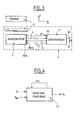
- the conditioner 3 receives on input terminals, referenced globally e C , the output signals e s generated by the transducer 1 (output terminals 1100 and 1200), via connecting son 4. It can include, as illustrated on FIG. 3, internal circuits (not shown) generating the current I 0 , radiofrequency f 0 . Naturally, this current can be generated by external circuits, but, in any case, it must be transmitted to the circuits of the conditioner 3, as specified below. In the example described, second connection wires 5 convey the current I 0 to the input terminals 1300 and 1310 of the transducer 1.
- the signal V s generated on output terminals, 30 and 31, of the conditioner 3 is obtained by synchronous demodulation of the signal e s with the aid of a reference signal at the frequency f 0 .
- Synchronous detection is known per se of the Man of Occupation, and it is useless to describe it in detail.
- the Synchronous demodulation can detect signals from very low amplitude, using amplifiers, circuit known under the name “Phase Locked Loop” or “PLL” (for “Phase Lock Loop”), and filters. These Signals are in practice undetectable by classical measures.
- the conditioner 3 is disposed at a distance from the assembly "transducer 1 - target 2".
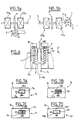
- FIG. 4 very schematically illustrates a synchronous detection circuit, referenced 33. It comprises two input channels, a reference signal V ref and the signal to be measured of very small amplitude, that is, e s , both characterized by an identical frequency f 0 .
- the reference signal V ref has an amplitude sufficient to be detectable in a conventional manner. It thus allows the synchronous detection circuit 33 to center the detection on the frequency f 0 . Therefore, the signal e s , a priori embedded in noise, is filtered at the input and at the output at the frequency f 0 , by filters (not shown) of appropriate selectivity, accompanied by a circuit of the "PLL" type mentioned above. .
- the time constant, which will be called T c , output filters reduces the bandwidth of the circuit "PLL", so as to position itself on f 0 more precisely. The noise staining the signal e s can then be virtually eliminated.
- the synchronous detection comprises four output terminals (not shown in detail) delivering, respectively, the actual component of the output signal V s , the imaginary component of this signal, its modulus and its phase.
- the target 2 is driven by the plate P, according to the reciprocating translation movement thereof (arrows f + and f - ), by means of a conventional mechanical fastening member. 7 subjecting it to the plateau P.
- the target 2 is driven by the rod T 1 at one of the ends of which it is secured by any appropriate conventional fastening means 7 '(not expressly shown).
- This rod T 1 drives the target 2 according to the reciprocal translation movement (arrows f + and f - ) thereof.
- transducer 1 is still in a space defined by the orthonormal trihedron XYZ ( Figure 2A).
- Conditioner 3 was not represent.
- the sensor 6 has a circular revolution configuration inside the spring R H , centered on the axis ⁇ S of the rod T 1 which extends it.
- the target 2 is secured to the rod T 1 by the conventional mechanical fastening means 7 'mentioned above.
- This target has several teeth 21.
- the transducer 1 is between a wall external tubular 8, preferably made of aluminum, and a wall internal tubular 9, of electrical insulating material, for example made of plastic
- the assembly is integral with the frame M of the actuator and is closed by a plug Bt for adjusting the stiffness of a spring (RH) and the positioning of the sensor relative to the target.
- This cap has an upper central opening OBt .
- conditioner 3 is preferentially arranged away from the set.
- the outer tube 8 of electrically conductive material contributes to protecting the transducer 1 against the influences of the magnetic fields outside the sensor 6, which vary with the movement of the springs, R B and R H ( Figure 1). This outer tube 8 thus provides good electromagnetic protection.
- the transducer 1 Since the transducer 1 is wrapped around a insulating material 9 that surrounds the target 2, the influences parasites due to possible dissymmetries between the target 2 and the transducer 1 are minimized. In addition, the insulating material 9 participates in transducer protection 1 against the aggressive environment in which he is immersed.
- the primary circuits 13 (see FIG. 2C) and 11 and 12 of the transducer 1 are flat coils printed or engraved on flexible circuits, advantageously polyimide films, for example based on Kapton® (brand filed by DuPont).
- the design of the primary and secondary circuits is likely to take many configurations.
- FIGS. 7A to 7L schematically represent various possible configurations of primary, 13 i , and secondary circuits, 11 i and 12 i , meeting the requirements for a transducer 1 i according to FIG. invention, i being an index which takes the values a to 1 for the respective figures 7A to 7L.
- the secondary circuits, 11 i and 12 i are mounted in "series-opposition" and these configurations have a perfect symmetry with respect to a central axis ⁇ (see Figure 2C).
- the support 10 may be identical from one configuration to another. For this reason, it is not associated with a particular index i .
- the sensor according to the invention implementing eddy currents and associated with synchronous demodulation presents many benefits that have been listed and that it is no need to call back. It authorizes in particular a telemetry.
Landscapes
- Engineering & Computer Science (AREA)
- Power Engineering (AREA)
- Physics & Mathematics (AREA)
- General Physics & Mathematics (AREA)
- Measurement Of Length, Angles, Or The Like Using Electric Or Magnetic Means (AREA)
- Valve Device For Special Equipments (AREA)
- Valve-Gear Or Valve Arrangements (AREA)
- Fuel-Injection Apparatus (AREA)
Abstract
Description
- l'exigence de la maítrise du niveau acoustique implique de connaítre la position du plateau avec une grande précision, typiquement une résolution de l'ordre de10 µm ;
- la plage de fonctionnement en température est large, par exemple comprise entre -50°C et +150°C ; et
- l'étendue de la mesure concerne un déplacement relativement faible, typiquement 8 mm, soit de +4mm à -4mm.
- gradients de température importants pouvant provoquer des dérives thermiques du signal de sortie du capteur, des jeux mécaniques aléatoires sur le système, une dilatation des matériaux ;
- exposition à des champs électromagnétiques extérieurs pouvant fausser les valeurs du signal de sortie du capteur ;
- exposition à un environnement physico-chimique agressif : présence d'humidité, d'hydrocarbures, fort taux d'encrassement, etc.
- ce matériau apporte une protection thermique des bobines ;
- ce matériau forme une protection contre l'environnement physico-chimique agressif dans lequel sont plongés les bobines du transducteur ; et
- la flexibilité du circuit souple permet d'insérer un transducteur de petite taille dans l'environnement réduit disponible des actionneurs électromagnétiques.
- la figure 1 illustre schématiquement un exemple de réalisation d'un actionneur électromagnétique pour soupape de moteur à combustion interne selon l'art connu ;
- la figure 2A illustre schématiquement un transducteur de position à courant de Foucault coopérant avec une cible selon un mode de réalisation préféré de l'invention ;
- la figure 2B illustre schématiquement des bobinages primaires et secondaires du transducteur de la figure 2A ;
- la figure 2C illustre l'agencement des bobinages primaire et secondaires du transducteur de la figure 2A ;
- la figure 2D représente la courbe de la tension de sortie du transducteur en fonction du déplacement de la cible suivant un axe ;
- la figure 3 illustre schématiquement un circuit conditionneur de la tension de sortie du transducteur mettant en oeuvre un détecteur synchrone ;
- la figure 4 illustre schématiquement le détecteur synchrone du circuit de la figure 3 ;
- les figures 5A et 5B illustrent schématiquement deux configurations de capteurs de position à courants de Foucault selon l'invention ;
- la figure 6 illustre schématiquement un exemple de réalisation pratique d'un capteur de position à courants de Foucault selon l'invention; et
- les figures 7A à 7L illustrent schématiquement des exemples de configurations de bobinages de transducteur sur des circuits souples.
- le nombre de spires N, trois dans l'exemple décrit ;
- la largeur des spires d, c'est-à-dire la largeur des traits gravés ou imprimés ;
- la largeur inter traits e ; et
- la largeur L d'encombrement de la bobine.
- la force électromotrice e 1 induite par la bobine primaire 13 dans la première bobine secondaire 11 ;
- la force électromotrice e 1f induite par les courants de Foucault présents dans la cible 2 dans la première bobine secondaire 11 ;
- la force électromotrice e 2 induite par la bobine primaire 13 dans la seconde bobine secondaire 12 ; et
- la force électromotrice e 2f induite par les courants de Foucault présents dans la cible 2 dans la seconde bobine secondaire 12.
- la distance h (figure 2A) entre la cible 2 et le transducteur 1 et le déplacement de la cible au-dessus du transducteur ;
- la nature du métal conducteur constituant la cible 2 ; et
- la forme de la cible 2 et la fréquence d'excitation f 0 du courant injecté I 0 dans la bobine primaire 13.
- Figure 5A : montage de la cible 2 entre les deux électro-aimants, haut EA H et bas EA B , de l'actionneur ; et
- Figure 5B : montage de la cible 2 en extrémité de la tige T 1 de l'actionneur.
- il apporte une protection thermique des circuits primaires et secondaires du transducteur ;
- il réalise une protection de ces circuits contre l'environnement physico-chimique agressif dans lequel ils sont plongés ; et
- la flexibilité du circuit souple en Kapton ® permet d'insérer un transducteur de petite taille dans l'environnement réduit disponible des actionneurs électromagnétiques.
Claims (17)
- Capteur de la position d'un premier organe assujetti à un actionneur de soupape, électromagnétique ou électromécanique, destiné à un moteur à combustion interne, cet organe étant animé d'un mouvement de translation alternatif selon une direction déterminée (X), en synchronisme avec celui de la soupape, caractérisé en ce qu'il comprend :un deuxième organe, dit cible (2), en matériau conducteur de l'électricité, assujetti au premier organe (P), de manière à suivre les mouvements de translations alternatifs,un transducteur (1) comprenant :un premier enroulement (13) dit primaire alimenté par un courant alternatif (I0) de fréquence déterminée,des deuxième et troisième enroulements (11, 12) connectés selon une configuration "série-opposition" par une première extrémité commune (1122), et couplés électromagnétiquement entre eux, l'enroulement primaire (13) induisant des courants de Foucault dans la cible (2) et étant couplé électromagnétiquement aux deuxième et troisième enroulements (11, 12),un support fixe (10) pour les premier à troisième enroulements (11, 12, 13), ces enroulements étant disposés de manière à ce qu'il se développe, par induction électromagnétique, entre les secondes extrémités (1100, 1200) des deuxième et troisième enroulements (11, 12), une tension de sortie (e s ) générée par le transducteur (1), proportionnelle à la différence entre les tensions induites par les courants de Foucault dans les deuxième et troisième enroulements (11, 12), respectivement, et,un circuit (3), dit conditionneur, recevant, sur une première voie d'entrée, la tension de sortie (e s ) et, sur une seconde voie d'entrée, un signal électrique alternatif (V Ref ) de référence, de fréquence identique à la fréquence déterminée, le circuit conditionneur (3) comprenant un circuit de démodulation synchrone, de manière à générer en sortie un signal électrique (V S ) représentatif de la position instantanée de la cible (2) le long de la direction déterminée (X).
- Capteur selon la revendication 1 caractérisé en ce que le conditionneur est déporté par rapport au transducteur, le conditionneur étant de préférence placé dans un lieu protégé des gradients thermiques importants et des agressions physico-chimiques.
- Capteur selon la revendication 1 ou 2 caractérisé en ce que les enroulements sont disposés symétriquement par rapport à un axe (A) lié au support (10).
- Capteur selon la revendication 1, 2 ou 3, caractérisé en ce que l'actionneur de soupape comprenant un plateau (P) disposé entre deux électroaimants, dits haut (E AH ) et bas (E HB ), le plateau (P) étant solidaire d'une tige d'entraínement (T 1 ) d'une soupape (S), le premier organe auquel est assujettie la cible est constitué par le plateau (P) ou par la tige d'entraínement.
- Capteur selon la revendication 1, 2 ou 3, caractérisé en ce que la soupape (S) étant prolongée par un organe dit queue de soupape, la cible (2) est solidaire de cette queue de soupape, celle-ci formant le premier organe et lui communiquant le mouvement de translation alternatif.
- Capteur selon l'une quelconque des revendications précédentes, caractérisé en ce que la fréquence déterminée est dans la gamme des radiofréquences, par exemple égale à 200 kHz environ.
- Capteur selon l'une quelconque des revendications précédentes, caractérisé en ce que la cible (2) est une tige métallique comprenant au moins une dent (21) disposée suivant la direction déterminée (X).
- Capteur selon la revendication 7, caractérisé en ce que le matériau conducteur de l'électricité de la cible (2) est de l'aluminium.
- Capteur selon l'une quelconque des revendications précédentes, caractérisé en ce que les premier à troisième enroulements (11, 12, 13) sont constitués de bobines plates, gravées ou imprimées sur un support souple (10).
- Capteur selon la revendication 9, caractérisé en ce que le support souple (10) est en polyimide.
- Capteur selon la revendication 9 ou 10, caractérisé en ce que l'enroulement primaire (13) comprend plusieurs spires bobinées autour des enroulements secondaires (11, 12) connectés en "série-opposition".
- Capteur selon l'une quelconque des revendications précédentes, caractérisé en ce que le circuit de démodulation synchrone (33) du circuit conditionneur (3) comprend une boucle à verrouillage phase (PLL).
- Capteur selon l'une quelconque des revendications précédentes, caractérisé en ce que, l'actionneur comportant un bâti (M), le transducteur (1) et la cible (2) sont disposés dans une ouverture de ce bâti, fermée par un bouchon (Bt) de réglage de la raideur d'un ressort (RH) et de positionnement du capteur par rapport à la cible, le transducteur (1) étant disposé coaxialement à la cible (2) à l'intérieur d'un tube (8) formant paroi externe.
- Capteur selon la revendication 13, caractérisé en ce que le tube (8) est en un matériau offrant une protection contre les champs électromagnétiques, par exemple en aluminium.
- Capteur selon la revendication 13 ou 14, caractérisé en ce que le transducteur (1) comporte une paroi interne (9) en matériau isolant électrique, par exemple en matière plastique.
- Capteur selon l'une quelconque des revendications précédentes, caractérisé en ce que le conditionneur (3) est à distance du transducteur (1) et de la cible (2), et en ce qu'il reçoit la tension de sortie (e s ) générée par le transducteur (1) par l'intermédiaire de fils de liaison (4), de manière à réaliser un système de télémesure.
- Capteur selon la revendication 16, caractérisé en ce que, le moteur comprenant une pluralité de soupapes (S) et d'actionneurs de soupapes, chacune des soupapes (S) étant associée à un transducteur (1), les circuits conditionneurs (3) recevant les tensions de sorties (e s ) générées par les transducteurs (1) sont regroupés en un circuit intégré unique, par exemple de type ASIC.
Applications Claiming Priority (2)
| Application Number | Priority Date | Filing Date | Title |
|---|---|---|---|
| FR0403617A FR2868526B1 (fr) | 2004-04-06 | 2004-04-06 | Capteur de position d'un actionneur de soupape d'un moteur a combustion interne |
| FR0403617 | 2004-04-06 |
Publications (2)
| Publication Number | Publication Date |
|---|---|
| EP1584899A1 true EP1584899A1 (fr) | 2005-10-12 |
| EP1584899B1 EP1584899B1 (fr) | 2007-07-04 |
Family
ID=34896718
Family Applications (1)
| Application Number | Title | Priority Date | Filing Date |
|---|---|---|---|
| EP05300178A Expired - Lifetime EP1584899B1 (fr) | 2004-04-06 | 2005-03-10 | Capteur de position d'un actionneur de soupape d'un moteur à combustion interne |
Country Status (6)
| Country | Link |
|---|---|
| US (1) | US7188592B2 (fr) |
| EP (1) | EP1584899B1 (fr) |
| AT (1) | ATE366406T1 (fr) |
| DE (1) | DE602005001518T2 (fr) |
| ES (1) | ES2286778T3 (fr) |
| FR (1) | FR2868526B1 (fr) |
Cited By (1)
| Publication number | Priority date | Publication date | Assignee | Title |
|---|---|---|---|---|
| FR2987116A1 (fr) * | 2012-02-21 | 2013-08-23 | Bosch Gmbh Robert | Dispositif de capteur pour detecter les angles de rotation d'un composant rotatif d'un vehicule |
Families Citing this family (22)
| Publication number | Priority date | Publication date | Assignee | Title |
|---|---|---|---|---|
| DE102004042486A1 (de) * | 2004-08-31 | 2006-03-16 | Siemens Ag | Vorrichtung und Verfahren zur Messung des Drehwinkels eines Rotors gegenüber einem Stator |
| WO2007056679A2 (fr) | 2005-11-03 | 2007-05-18 | The Clock Spring Company L.P. | Réseau à courant de foucault convivial |
| CN100501315C (zh) * | 2006-01-06 | 2009-06-17 | 鸿富锦精密工业(深圳)有限公司 | 一种表面轮廓检测方法 |
| US8635930B2 (en) * | 2007-06-22 | 2014-01-28 | Ksr Technologies Co. | Floor mounted pedal with position sensor |
| EP2715152B1 (fr) * | 2011-06-01 | 2016-11-30 | Schaeffler Technologies AG & Co. KG | Ensemble piston-cylindre équipé d'un capteur de mesure de course |
| DE102011112274A1 (de) | 2011-09-05 | 2013-03-07 | Brose Fahrzeugteile Gmbh & Co. Kg, Hallstadt | Steuersystem |
| DE102011121775B3 (de) | 2011-12-21 | 2013-01-31 | Brose Fahrzeugteile Gmbh & Co. Kg, Hallstadt | Steuersystem |
| US20130251502A1 (en) * | 2012-03-20 | 2013-09-26 | World Heart Corporation | Method and Apparatus for Sensing of Levitated Rotor Position |
| DE102012013065A1 (de) | 2012-07-02 | 2014-01-02 | Brose Fahrzeugteile Gmbh & Co. Kg, Hallstadt | Verfahren zur Ansteuerung einer Verschlusselementanordnung eines Kraftfahrzeugs |
| DE102012014676A1 (de) * | 2012-07-25 | 2014-01-30 | Brose Fahrzeugteile Gmbh & Co. Kg, Hallstadt | Verfahren zur Ansteuerung einer Verschlusselementanordnung insbesondere eines Kraftfahrzeugs |
| CN105308418B (zh) * | 2013-06-13 | 2018-05-08 | 株式会社阿米泰克 | 感应型位置检测装置 |
| DE102013019168B4 (de) * | 2013-08-02 | 2015-11-12 | Hahn-Schickard-Gesellschaft für angewandte Forschung e.V. | Sensor zum anzeigen einer position oder einer positionsänderung eines kopplungselementes und verfahren zum betrieb des sensors |
| JP6147658B2 (ja) * | 2013-12-18 | 2017-06-14 | 三菱重工工作機械株式会社 | 電磁誘導式位置検出器及び検出方法 |
| DE102013114883A1 (de) | 2013-12-25 | 2015-06-25 | Brose Fahrzeugteile Gmbh & Co. Kommanditgesellschaft, Hallstadt | Steuersystem für eine motorische Verschlusselementanordnung eines Kraftfahrzeugs |
| DE102013114881A1 (de) | 2013-12-25 | 2015-06-25 | Brose Fahrzeugteile Gmbh & Co. Kommanditgesellschaft, Hallstadt | Steuersystem für eine motorische Verschlusselementanordnung eines Kraftfahrzeugs |
| AU2014406529B2 (en) * | 2014-09-15 | 2019-10-31 | Flowserve Pte. Ltd. | Sensors for valve systems and related assemblies, systems and methods |
| DE102015112589A1 (de) | 2015-07-31 | 2017-02-02 | Brose Fahrzeugteile Gmbh & Co. Kommanditgesellschaft, Bamberg | Steuersystem für eine motorisch verstellbare Laderaumvorrichtung eines Kraftfahrzeugs |
| DE102015119701A1 (de) | 2015-11-15 | 2017-05-18 | Brose Fahrzeugteile Gmbh & Co. Kommanditgesellschaft, Bamberg | Verfahren für den Betrieb einer kapazitiven Sensoranordnung eines Kraftfahrzeugs |
| JP7084807B2 (ja) * | 2018-07-10 | 2022-06-15 | オークマ株式会社 | 電磁誘導型位置センサ用のセンサ基板、および、センサ基板の製造方法 |
| US11248717B2 (en) | 2019-06-28 | 2022-02-15 | Automatic Switch Company | Modular smart solenoid valve |
| CN114018351B (zh) * | 2021-10-20 | 2024-01-23 | 新郦璞科技(上海)有限公司 | 基于电涡流感应原理的电子膜式燃气表计量系统 |
| DE102022124480A1 (de) * | 2022-09-23 | 2024-03-28 | R. Stahl Schaltgeräte GmbH | Dichtungsanordnung und Verfahren zur Zustands- und/oder Leckagenüberwachung der Dichtung |
Citations (5)
| Publication number | Priority date | Publication date | Assignee | Title |
|---|---|---|---|---|
| US4100480A (en) * | 1976-08-20 | 1978-07-11 | Dataproducts Corporation | Position and velocity sensors |
| DE3329515A1 (de) * | 1983-08-16 | 1985-03-07 | Krohne Meßtechnik GmbH & Co KG, 4100 Duisburg | Elektrische schaltanordnung fuer einen magnetisch-induktiven messwertgeber |
| DE3602107A1 (de) * | 1986-01-24 | 1987-07-30 | Bosch Gmbh Robert | Schaltungsanordnung mit differentialtransformator |
| US20020097042A1 (en) * | 2001-01-24 | 2002-07-25 | Texas Instruments Incorporated | Non-contact position sensor and method |
| US6681728B2 (en) * | 2001-11-05 | 2004-01-27 | Ford Global Technologies, Llc | Method for controlling an electromechanical actuator for a fuel air charge valve |
Family Cites Families (1)
| Publication number | Priority date | Publication date | Assignee | Title |
|---|---|---|---|---|
| FR2784712B1 (fr) * | 1998-10-15 | 2001-09-14 | Sagem | Procede et dispositif d'actionnement electromagnetique de soupape |
-
2004
- 2004-04-06 FR FR0403617A patent/FR2868526B1/fr not_active Expired - Fee Related
-
2005
- 2005-03-10 ES ES05300178T patent/ES2286778T3/es not_active Expired - Lifetime
- 2005-03-10 EP EP05300178A patent/EP1584899B1/fr not_active Expired - Lifetime
- 2005-03-10 AT AT05300178T patent/ATE366406T1/de not_active IP Right Cessation
- 2005-03-10 DE DE602005001518T patent/DE602005001518T2/de not_active Expired - Lifetime
- 2005-04-06 US US11/100,057 patent/US7188592B2/en not_active Expired - Lifetime
Patent Citations (5)
| Publication number | Priority date | Publication date | Assignee | Title |
|---|---|---|---|---|
| US4100480A (en) * | 1976-08-20 | 1978-07-11 | Dataproducts Corporation | Position and velocity sensors |
| DE3329515A1 (de) * | 1983-08-16 | 1985-03-07 | Krohne Meßtechnik GmbH & Co KG, 4100 Duisburg | Elektrische schaltanordnung fuer einen magnetisch-induktiven messwertgeber |
| DE3602107A1 (de) * | 1986-01-24 | 1987-07-30 | Bosch Gmbh Robert | Schaltungsanordnung mit differentialtransformator |
| US20020097042A1 (en) * | 2001-01-24 | 2002-07-25 | Texas Instruments Incorporated | Non-contact position sensor and method |
| US6681728B2 (en) * | 2001-11-05 | 2004-01-27 | Ford Global Technologies, Llc | Method for controlling an electromechanical actuator for a fuel air charge valve |
Cited By (1)
| Publication number | Priority date | Publication date | Assignee | Title |
|---|---|---|---|---|
| FR2987116A1 (fr) * | 2012-02-21 | 2013-08-23 | Bosch Gmbh Robert | Dispositif de capteur pour detecter les angles de rotation d'un composant rotatif d'un vehicule |
Also Published As
| Publication number | Publication date |
|---|---|
| EP1584899B1 (fr) | 2007-07-04 |
| ATE366406T1 (de) | 2007-07-15 |
| DE602005001518T2 (de) | 2008-03-06 |
| US7188592B2 (en) | 2007-03-13 |
| US20050231194A1 (en) | 2005-10-20 |
| FR2868526B1 (fr) | 2007-04-20 |
| ES2286778T3 (es) | 2007-12-01 |
| DE602005001518D1 (de) | 2007-08-16 |
| FR2868526A1 (fr) | 2005-10-07 |
Similar Documents
| Publication | Publication Date | Title |
|---|---|---|
| EP1584899B1 (fr) | Capteur de position d'un actionneur de soupape d'un moteur à combustion interne | |
| EP0729582B1 (fr) | Capteur incremental de vitesse et/ou de position | |
| EP3790166A1 (fr) | Actionneur magnétique et système mécatronique | |
| EP1102995B1 (fr) | Roulement equipe d'un dispositif capteur d'informations | |
| EP2326919A2 (fr) | Capteur de position lineaire ou rotatif a aimant permanent pour la detection d'une cible ferromagnetique | |
| FR2954823A1 (fr) | Procede de determination de la position d'un element magnetique utilisant des capteurs a effet hall lineaires et dispositif associe | |
| FR2629210A1 (fr) | Capteur pour vehicule automobile a regulation electronique de certaines variables concernant sa dynamique | |
| CA2397187A1 (fr) | Composant microelectromecanique | |
| FR3071605A1 (fr) | Module de detection d’une poignee rotative d’un vehicule motorise | |
| WO2019048780A1 (fr) | Procédé de définition d'une plage de mesure d'un capteur de position inductif | |
| WO2012059149A1 (fr) | Procede et dispositif de determination de la position d'un element magnetique utilisant des cellules a effet hall lineaires | |
| FR3041748A1 (fr) | Dispositif pour compenser des champs magnetiques parasites externes ou pour compenser l'influence d'un gradient de champ magnetique sur un capteur de champ magnetique | |
| FR2827962A1 (fr) | Dispositif de mesure a effet hall de l'intensite d'un courant electrique | |
| FR2801969A1 (fr) | Capteur analogique de decalage angulaire sans contact | |
| FR2995488A1 (fr) | Dispositif transducteur acoustique et son procede de fabrication | |
| EP2511665B1 (fr) | Dispositif de détection de la position axiale d'un arbre tournant et application à une pompe turbo-moléculaire | |
| FR2748805A1 (fr) | Capteur de position sans contact, a effet hall | |
| EP1166295B1 (fr) | Procede pour la determination de la position d'un organe mobile dans au moins un entrefer principal d'un actionneur electromagnetique | |
| FR3123118A1 (fr) | Dispositif de détection de position pour véhicule | |
| FR2693799A1 (fr) | Capteur de vitesses angulaires, notamment destiné à des véhicules automobiles. | |
| EP0069073A1 (fr) | Dispositif de mesure de force | |
| FR3043197A1 (fr) | Dispositif a double cible pour la determination de la position d'un axe mobile d'un vehicule automobile | |
| EP0389390B1 (fr) | Micromagnétomètre à poutre fléchissante | |
| FR2716713A1 (fr) | Installation pour mesurer une course ou un angle. | |
| EP1353185A2 (fr) | Capteur inertiel à sonde de température intégrée |
Legal Events
| Date | Code | Title | Description |
|---|---|---|---|
| PUAI | Public reference made under article 153(3) epc to a published international application that has entered the european phase |
Free format text: ORIGINAL CODE: 0009012 |
|
| AK | Designated contracting states |
Kind code of ref document: A1 Designated state(s): AT BE BG CH CY CZ DE DK EE ES FI FR GB GR HU IE IS IT LI LT LU MC NL PL PT RO SE SI SK TR |
|
| AX | Request for extension of the european patent |
Extension state: AL BA HR LV MK YU |
|
| 17P | Request for examination filed |
Effective date: 20060311 |
|
| AKX | Designation fees paid |
Designated state(s): AT BE BG CH CY CZ DE DK EE ES FI FR GB GR HU IE IS IT LI LT LU MC NL PL PT RO SE SI SK TR |
|
| 17Q | First examination report despatched |
Effective date: 20060720 |
|
| GRAP | Despatch of communication of intention to grant a patent |
Free format text: ORIGINAL CODE: EPIDOSNIGR1 |
|
| GRAS | Grant fee paid |
Free format text: ORIGINAL CODE: EPIDOSNIGR3 |
|
| GRAA | (expected) grant |
Free format text: ORIGINAL CODE: 0009210 |
|
| AK | Designated contracting states |
Kind code of ref document: B1 Designated state(s): AT BE BG CH CY CZ DE DK EE ES FI FR GB GR HU IE IS IT LI LT LU MC NL PL PT RO SE SI SK TR |
|
| REG | Reference to a national code |
Ref country code: GB Ref legal event code: FG4D Free format text: NOT ENGLISH |
|
| REG | Reference to a national code |
Ref country code: CH Ref legal event code: EP |
|
| GBT | Gb: translation of ep patent filed (gb section 77(6)(a)/1977) |
Effective date: 20070718 |
|
| REG | Reference to a national code |
Ref country code: IE Ref legal event code: FG4D Free format text: LANGUAGE OF EP DOCUMENT: FRENCH |
|
| REF | Corresponds to: |
Ref document number: 602005001518 Country of ref document: DE Date of ref document: 20070816 Kind code of ref document: P |
|
| REG | Reference to a national code |
Ref country code: ES Ref legal event code: FG2A Ref document number: 2286778 Country of ref document: ES Kind code of ref document: T3 |
|
| NLV1 | Nl: lapsed or annulled due to failure to fulfill the requirements of art. 29p and 29m of the patents act | ||
| PG25 | Lapsed in a contracting state [announced via postgrant information from national office to epo] |
Ref country code: LT Free format text: LAPSE BECAUSE OF FAILURE TO SUBMIT A TRANSLATION OF THE DESCRIPTION OR TO PAY THE FEE WITHIN THE PRESCRIBED TIME-LIMIT Effective date: 20070704 Ref country code: IS Free format text: LAPSE BECAUSE OF FAILURE TO SUBMIT A TRANSLATION OF THE DESCRIPTION OR TO PAY THE FEE WITHIN THE PRESCRIBED TIME-LIMIT Effective date: 20071104 Ref country code: BG Free format text: LAPSE BECAUSE OF FAILURE TO SUBMIT A TRANSLATION OF THE DESCRIPTION OR TO PAY THE FEE WITHIN THE PRESCRIBED TIME-LIMIT Effective date: 20071004 Ref country code: FI Free format text: LAPSE BECAUSE OF FAILURE TO SUBMIT A TRANSLATION OF THE DESCRIPTION OR TO PAY THE FEE WITHIN THE PRESCRIBED TIME-LIMIT Effective date: 20070704 Ref country code: PT Free format text: LAPSE BECAUSE OF FAILURE TO SUBMIT A TRANSLATION OF THE DESCRIPTION OR TO PAY THE FEE WITHIN THE PRESCRIBED TIME-LIMIT Effective date: 20071204 Ref country code: NL Free format text: LAPSE BECAUSE OF FAILURE TO SUBMIT A TRANSLATION OF THE DESCRIPTION OR TO PAY THE FEE WITHIN THE PRESCRIBED TIME-LIMIT Effective date: 20070704 Ref country code: SI Free format text: LAPSE BECAUSE OF FAILURE TO SUBMIT A TRANSLATION OF THE DESCRIPTION OR TO PAY THE FEE WITHIN THE PRESCRIBED TIME-LIMIT Effective date: 20070704 |
|
| PG25 | Lapsed in a contracting state [announced via postgrant information from national office to epo] |
Ref country code: PL Free format text: LAPSE BECAUSE OF FAILURE TO SUBMIT A TRANSLATION OF THE DESCRIPTION OR TO PAY THE FEE WITHIN THE PRESCRIBED TIME-LIMIT Effective date: 20070704 Ref country code: AT Free format text: LAPSE BECAUSE OF FAILURE TO SUBMIT A TRANSLATION OF THE DESCRIPTION OR TO PAY THE FEE WITHIN THE PRESCRIBED TIME-LIMIT Effective date: 20070704 |
|
| REG | Reference to a national code |
Ref country code: IE Ref legal event code: FD4D |
|
| REG | Reference to a national code |
Ref country code: GB Ref legal event code: 746 Effective date: 20080329 |
|
| PG25 | Lapsed in a contracting state [announced via postgrant information from national office to epo] |
Ref country code: DK Free format text: LAPSE BECAUSE OF FAILURE TO SUBMIT A TRANSLATION OF THE DESCRIPTION OR TO PAY THE FEE WITHIN THE PRESCRIBED TIME-LIMIT Effective date: 20070704 Ref country code: GR Free format text: LAPSE BECAUSE OF FAILURE TO SUBMIT A TRANSLATION OF THE DESCRIPTION OR TO PAY THE FEE WITHIN THE PRESCRIBED TIME-LIMIT Effective date: 20071005 |
|
| PLBE | No opposition filed within time limit |
Free format text: ORIGINAL CODE: 0009261 |
|
| STAA | Information on the status of an ep patent application or granted ep patent |
Free format text: STATUS: NO OPPOSITION FILED WITHIN TIME LIMIT |
|
| PG25 | Lapsed in a contracting state [announced via postgrant information from national office to epo] |
Ref country code: SK Free format text: LAPSE BECAUSE OF FAILURE TO SUBMIT A TRANSLATION OF THE DESCRIPTION OR TO PAY THE FEE WITHIN THE PRESCRIBED TIME-LIMIT Effective date: 20070704 Ref country code: IE Free format text: LAPSE BECAUSE OF FAILURE TO SUBMIT A TRANSLATION OF THE DESCRIPTION OR TO PAY THE FEE WITHIN THE PRESCRIBED TIME-LIMIT Effective date: 20070704 Ref country code: CZ Free format text: LAPSE BECAUSE OF FAILURE TO SUBMIT A TRANSLATION OF THE DESCRIPTION OR TO PAY THE FEE WITHIN THE PRESCRIBED TIME-LIMIT Effective date: 20070704 |
|
| 26N | No opposition filed |
Effective date: 20080407 |
|
| PG25 | Lapsed in a contracting state [announced via postgrant information from national office to epo] |
Ref country code: SE Free format text: LAPSE BECAUSE OF FAILURE TO SUBMIT A TRANSLATION OF THE DESCRIPTION OR TO PAY THE FEE WITHIN THE PRESCRIBED TIME-LIMIT Effective date: 20071004 Ref country code: RO Free format text: LAPSE BECAUSE OF FAILURE TO SUBMIT A TRANSLATION OF THE DESCRIPTION OR TO PAY THE FEE WITHIN THE PRESCRIBED TIME-LIMIT Effective date: 20070704 |
|
| BERE | Be: lapsed |
Owner name: PEUGEOT CITROEN AUTOMOBILES SA Effective date: 20080331 |
|
| PG25 | Lapsed in a contracting state [announced via postgrant information from national office to epo] |
Ref country code: MC Free format text: LAPSE BECAUSE OF NON-PAYMENT OF DUE FEES Effective date: 20080331 |
|
| PG25 | Lapsed in a contracting state [announced via postgrant information from national office to epo] |
Ref country code: EE Free format text: LAPSE BECAUSE OF FAILURE TO SUBMIT A TRANSLATION OF THE DESCRIPTION OR TO PAY THE FEE WITHIN THE PRESCRIBED TIME-LIMIT Effective date: 20070704 |
|
| PG25 | Lapsed in a contracting state [announced via postgrant information from national office to epo] |
Ref country code: BE Free format text: LAPSE BECAUSE OF NON-PAYMENT OF DUE FEES Effective date: 20080331 |
|
| PG25 | Lapsed in a contracting state [announced via postgrant information from national office to epo] |
Ref country code: CY Free format text: LAPSE BECAUSE OF FAILURE TO SUBMIT A TRANSLATION OF THE DESCRIPTION OR TO PAY THE FEE WITHIN THE PRESCRIBED TIME-LIMIT Effective date: 20070704 |
|
| REG | Reference to a national code |
Ref country code: CH Ref legal event code: PL |
|
| PG25 | Lapsed in a contracting state [announced via postgrant information from national office to epo] |
Ref country code: CH Free format text: LAPSE BECAUSE OF NON-PAYMENT OF DUE FEES Effective date: 20090331 Ref country code: LI Free format text: LAPSE BECAUSE OF NON-PAYMENT OF DUE FEES Effective date: 20090331 |
|
| PG25 | Lapsed in a contracting state [announced via postgrant information from national office to epo] |
Ref country code: LU Free format text: LAPSE BECAUSE OF NON-PAYMENT OF DUE FEES Effective date: 20080310 Ref country code: HU Free format text: LAPSE BECAUSE OF FAILURE TO SUBMIT A TRANSLATION OF THE DESCRIPTION OR TO PAY THE FEE WITHIN THE PRESCRIBED TIME-LIMIT Effective date: 20080105 |
|
| PG25 | Lapsed in a contracting state [announced via postgrant information from national office to epo] |
Ref country code: TR Free format text: LAPSE BECAUSE OF FAILURE TO SUBMIT A TRANSLATION OF THE DESCRIPTION OR TO PAY THE FEE WITHIN THE PRESCRIBED TIME-LIMIT Effective date: 20070704 |
|
| REG | Reference to a national code |
Ref country code: ES Ref legal event code: GC2A Effective date: 20130213 |
|
| REG | Reference to a national code |
Ref country code: FR Ref legal event code: PLFP Year of fee payment: 12 |
|
| REG | Reference to a national code |
Ref country code: FR Ref legal event code: PLFP Year of fee payment: 13 |
|
| REG | Reference to a national code |
Ref country code: FR Ref legal event code: PLFP Year of fee payment: 14 |
|
| PGFP | Annual fee paid to national office [announced via postgrant information from national office to epo] |
Ref country code: IT Payment date: 20180219 Year of fee payment: 14 |
|
| REG | Reference to a national code |
Ref country code: FR Ref legal event code: CA Effective date: 20180312 Ref country code: FR Ref legal event code: CD Owner name: PEUGEOT CITROEN AUTOMOBILES SA, FR Effective date: 20180312 |
|
| PGFP | Annual fee paid to national office [announced via postgrant information from national office to epo] |
Ref country code: ES Payment date: 20180403 Year of fee payment: 14 |
|
| PGFP | Annual fee paid to national office [announced via postgrant information from national office to epo] |
Ref country code: GB Payment date: 20190222 Year of fee payment: 15 |
|
| PG25 | Lapsed in a contracting state [announced via postgrant information from national office to epo] |
Ref country code: IT Free format text: LAPSE BECAUSE OF NON-PAYMENT OF DUE FEES Effective date: 20190310 |
|
| PGFP | Annual fee paid to national office [announced via postgrant information from national office to epo] |
Ref country code: DE Payment date: 20200218 Year of fee payment: 16 |
|
| PGFP | Annual fee paid to national office [announced via postgrant information from national office to epo] |
Ref country code: FR Payment date: 20200220 Year of fee payment: 16 |
|
| REG | Reference to a national code |
Ref country code: ES Ref legal event code: FD2A Effective date: 20200724 |
|
| PG25 | Lapsed in a contracting state [announced via postgrant information from national office to epo] |
Ref country code: ES Free format text: LAPSE BECAUSE OF NON-PAYMENT OF DUE FEES Effective date: 20190311 |
|
| GBPC | Gb: european patent ceased through non-payment of renewal fee |
Effective date: 20200310 |
|
| PG25 | Lapsed in a contracting state [announced via postgrant information from national office to epo] |
Ref country code: GB Free format text: LAPSE BECAUSE OF NON-PAYMENT OF DUE FEES Effective date: 20200310 |
|
| REG | Reference to a national code |
Ref country code: DE Ref legal event code: R119 Ref document number: 602005001518 Country of ref document: DE |
|
| PG25 | Lapsed in a contracting state [announced via postgrant information from national office to epo] |
Ref country code: FR Free format text: LAPSE BECAUSE OF NON-PAYMENT OF DUE FEES Effective date: 20210331 Ref country code: DE Free format text: LAPSE BECAUSE OF NON-PAYMENT OF DUE FEES Effective date: 20211001 |