EP1584843A2 - Hydraulic tensioner - Google Patents
Hydraulic tensioner Download PDFInfo
- Publication number
- EP1584843A2 EP1584843A2 EP05005820A EP05005820A EP1584843A2 EP 1584843 A2 EP1584843 A2 EP 1584843A2 EP 05005820 A EP05005820 A EP 05005820A EP 05005820 A EP05005820 A EP 05005820A EP 1584843 A2 EP1584843 A2 EP 1584843A2
- Authority
- EP
- European Patent Office
- Prior art keywords
- ball
- plunger
- ball guide
- check
- check valve
- Prior art date
- Legal status (The legal status is an assumption and is not a legal conclusion. Google has not performed a legal analysis and makes no representation as to the accuracy of the status listed.)
- Granted
Links
Images



Classifications
-
- F—MECHANICAL ENGINEERING; LIGHTING; HEATING; WEAPONS; BLASTING
- F16—ENGINEERING ELEMENTS AND UNITS; GENERAL MEASURES FOR PRODUCING AND MAINTAINING EFFECTIVE FUNCTIONING OF MACHINES OR INSTALLATIONS; THERMAL INSULATION IN GENERAL
- F16H—GEARING
- F16H7/00—Gearings for conveying rotary motion by endless flexible members
- F16H7/08—Means for varying tension of belts, ropes or chains
- F16H7/0848—Means for varying tension of belts, ropes or chains with means for impeding reverse motion
-
- F—MECHANICAL ENGINEERING; LIGHTING; HEATING; WEAPONS; BLASTING
- F16—ENGINEERING ELEMENTS AND UNITS; GENERAL MEASURES FOR PRODUCING AND MAINTAINING EFFECTIVE FUNCTIONING OF MACHINES OR INSTALLATIONS; THERMAL INSULATION IN GENERAL
- F16H—GEARING
- F16H7/00—Gearings for conveying rotary motion by endless flexible members
- F16H7/08—Means for varying tension of belts, ropes or chains
- F16H2007/0802—Actuators for final output members
- F16H2007/0806—Compression coil springs
-
- F—MECHANICAL ENGINEERING; LIGHTING; HEATING; WEAPONS; BLASTING
- F16—ENGINEERING ELEMENTS AND UNITS; GENERAL MEASURES FOR PRODUCING AND MAINTAINING EFFECTIVE FUNCTIONING OF MACHINES OR INSTALLATIONS; THERMAL INSULATION IN GENERAL
- F16H—GEARING
- F16H7/00—Gearings for conveying rotary motion by endless flexible members
- F16H7/08—Means for varying tension of belts, ropes or chains
- F16H2007/0802—Actuators for final output members
- F16H2007/0812—Fluid pressure
-
- F—MECHANICAL ENGINEERING; LIGHTING; HEATING; WEAPONS; BLASTING
- F16—ENGINEERING ELEMENTS AND UNITS; GENERAL MEASURES FOR PRODUCING AND MAINTAINING EFFECTIVE FUNCTIONING OF MACHINES OR INSTALLATIONS; THERMAL INSULATION IN GENERAL
- F16H—GEARING
- F16H7/00—Gearings for conveying rotary motion by endless flexible members
- F16H7/08—Means for varying tension of belts, ropes or chains
- F16H7/0848—Means for varying tension of belts, ropes or chains with means for impeding reverse motion
- F16H2007/0853—Ratchets
-
- F—MECHANICAL ENGINEERING; LIGHTING; HEATING; WEAPONS; BLASTING
- F16—ENGINEERING ELEMENTS AND UNITS; GENERAL MEASURES FOR PRODUCING AND MAINTAINING EFFECTIVE FUNCTIONING OF MACHINES OR INSTALLATIONS; THERMAL INSULATION IN GENERAL
- F16H—GEARING
- F16H7/00—Gearings for conveying rotary motion by endless flexible members
- F16H7/08—Means for varying tension of belts, ropes or chains
- F16H7/0848—Means for varying tension of belts, ropes or chains with means for impeding reverse motion
- F16H2007/0859—Check valves
Definitions
- This invention relates to hydraulic tensioners of the type used to apply proper tension to the timing chain or timing belt of an internal combustion engine, and relates more particularly to improvements in the check valve of a hydraulic tensioner.
- Hydraulic tensioners have been widely used to maintain tension in timing chains and timing belts which transmit rotation from the crankshaft to one or more camshafts of a vehicle engine. By maintaining proper tension, the tensioner prevents vibration of the chain or belt.
- a conventional hydraulic tensioner includes a housing having a cylindrical hole, a plunger slidable in the cylindrical hole and protruding from an opening at the end thereof, and a plunger-biasing spring urging the plunger in the protruding direction.
- the housing and the plunger together form a high pressure oil chamber, and a check valve mechanism, comprising a metal cylinder, is fitted into the cylindrical hole of the housing to permit entry of oil into the high pressure oil chamber, but prevent reverse flow of oil out of the chamber.
- the check valve mechanism is pre-assembled before being fitted into the cylindrical hole of the housing, and comprises cylindrical element providing an oil passage and having a ball seat formed thereon, a check ball, a coil spring, and a lid.
- An example of a conventional check valve mechanism is described in Japanese Laid-Open Patent Publication No. 2002-206603 (page 1, FIG. 1).
- the check valve unit 540 comprises a synthetic resin ball guide 542, a ball seat 544 attached to the ball guide, a check ball 541 disposed in opposed relationship to the valve seat and guided by the ball guide 542, a check ball-biasing spring 545, which biases the check ball 541 toward the valve seat, and a disc-shaped retainer 543, which limits the extent to which the check ball 541 can move away from the ball seat 544. As shown in FIGs.
- two protrusions 542a are provided on opposite sides of the center of the ball guide 542 on the high pressure chamber side thereof.
- An outer circumferential tongue 542b is provided on the ball guide for pressing against the wall of the plunger accommodating hole, adjacent the bottom end thereof.
- Four crimped protrusions 542c are provided at four locations on the outer circumference of the ball guide at the inlet side thereof.
- the retainer 543 is provided with holes 543a for receiving the protrusions 542a.
- An oil communication hole 543b is provided in the retainer 543.
- a valve seat 544a is provided on the ball seat 544 for abutting engagement with the check ball 541, and the ball seat is held in place by the four crimped protrusions 542c.
- the two protrusions 542a, which hold the retainer to the ball guide, are inserted into holes 543a of the retainer 543, and then crimped in order to fix the retainer to the ball guide.
- Object of this invention is to provide a hydraulic tensioner which can be assembled easily, and in which the check valve unit can be readily assembled and incorporated into the tensioner easily and securely.
- the hydraulic tensioner in accordance with the invention comprises a housing having a plunger-accommodating hole formed therein, and a plunger.
- the plunger-accommodating hole has an opening at one end thereof and a bottom portion at the opposite end thereof.
- a plunger is slidable in the plunger-accommodating hole and protrudes through the opening in order to apply tension to a chain, a belt, or a similar traveling, flexible power transmission medium.
- the plunger and the housing together form a high-pressure oil chamber.
- the tensioner also includes a plunger-biasing spring, accommodated in the high pressure oil chamber. The spring biases the plunger in a protruding direction.
- a check valve unit is incorporated into the housing, within the plunger-accommodating hole and adjacent the bottom portion thereof.
- the check valve unit is arranged to allow flow of oil into the high-pressure oil chamber, and to prevent reverse flow of oil.
- the check valve unit has an outlet side facing the high pressure oil chamber and an opposite inflow side.
- the check valve unit comprises a check ball, a ball seat on which the check ball can be seated to block reverse flow of oil out of the high pressure oil chamber, a ball guide in which the check ball is freely movable toward and away from the ball seat, and a disc-shaped retainer holding the check ball in the ball guide while allowing movement of the check ball within the ball guide toward and away from the ball seat.
- the disc-shaped retainer has a surface facing the high pressure oil chamber. This surface has an annular peripheral region, and the ball guide has an annular portion on its high pressure oil chamber side. A part of the annular portion surrounds the disc-shaped retainer and a part of the annular portion is crimped over substantially the entirety of the annular peripheral region of the disc-shaped retainer.
- the annular portion of the ball guide forms a recess
- an end portion of the plunger-biasing spring extends into the recess, bears axially against the disc-shaped retainer, and is engaged with the annular portion of the ball guide and held thereby against radial movement.
- the ball seat also has an annular peripheral region and is fixed to the ball guide by an annular crimped portion of he ball guide on the inflow side thereof. This crimped portion is crimped over substantially the entirety of the annular peripheral region of said ball seat.
- the hydraulic tensioner of the invention maintains proper tension in a chain, a belt, or other traveling flexible power transmission medium in the same manner as a conventional hydraulic tensioner.
- the tensioner exhibits a number of significant advantages over the conventional tensioner.
- the disc-shaped retainer is fixed to the ball guide by crimping the ball guide over an annular region that extends substantially entirely around the periphery of the retainer. Accordingly, in contrast with the tensioner shown in FIGs. 6 and 7, in the tensioner according to the invention, the crimped portion of the ball guide provides for a stronger check valve unit, and allows the check valve unit to be assembled without careful positioning of the retainer relative to the ball guide. Furthermore, because the retainer is more securely attached to the ball guide, the check valve unit can be incorporated into the bottom portion of the plunger-accommodating hole without the risk of detachment of the retainer from the ball guide.
- annular portion of the ball guide can form a recess for receiving and reliably positioning an end portion of the plunger-biasing spring, thereby avoiding wear and contact noise which would otherwise result from abnormal contact between the rear end portion of the plunger and the plunger-biasing spring.
- a further advantage is afforded where the ball seat is fixed to the ball guide by an annular crimped portion of he ball guide on the inflow side thereof, and the crimped portion is crimped over substantially the entirety of an annular peripheral region of the ball seat.
- the ball guide of the check valve unit may be composed of a synthetic resin or metal. However, it is preferably composed of synthetic resin so that crimping can be carried out by the application of heat, and assembly of the check valve unit can be carried out quickly and easily.
- a hydraulic tensioner 100 in accordance with a first embodiment of the invention, is attached to an engine block adjacent the slack side of a timing chain C, which is in mesh with a drive sprocket S1 rotated by a crankshaft of an engine and driven sprockets S2 on valve-operating camshafts.
- a plunger 120 protrudes through an opening of a cylindrical plunger-accommodating hole 111 in a tensioner housing 110, and applies tension to the slack side of the chain C through a pivoted lever L1 by pressing against a back surface of the lever at a location remote from the lever's pivot axis.
- a fixed guide L2 guides the travel of the timing chain C on the tension side thereof. Arrows in FIG. 1 indicate the directions of rotation of the sprockets and the direction of movement of the chain C.
- the exterior of the plunger 120 is cylindrical, and the plunger fits slidably in the plunger-accommodating hole 111.
- a high pressure oil chamber R is formed by the plunger 120 and the plunger-accommodating hole 111.
- a coil spring 130 serving as a plunger biasing spring, is accommodated within chamber R, and biases the plunger 120 in the protruding direction.
- a check valve unit 140 is incorporated into the tensioner at the bottom of the plunger-accommodating hole 111.
- the check valve unit allows oil, supplied from the engine through a passage (not shown), to flow into the high pressure chamber R, but blocks reverse flow of oil.
- the check valve unit 140 is an assembly comprising a check ball 141, a synthetic resin ball guide 142, which envelopes the check ball and in which the check ball 141 is freely movable, a disc-shaped retainer 143 on the high pressure oil chamber side of the ball guide 142 for maintaining the check ball 141 in the ball guide 142, and a metal ball seat 144, fixed to the ball guide 142 on the inflow side.
- the ball is engageable with the seat to block reverse flow of oil out of the high pressure oil chamber R.
- the disc-shaped retainer 143 is fixed to the ball guide 142 by crimping a portion of the ball guide over the retainer. Crimping a portion of the ball guide over the retainer in this manner provides a stronger assembly than in the case of the hydraulic tensioner 500 shown in FIGs. 6 - 7C.
- an outer circumferential tongue 142b is provided on the ball guide for pressing against the cylindrical side wall of the plunger-accommodating hole 111 in order to secure the check valve unit in place at the bottom of the plunger-accommodating hole.
- Oil communication holes 143a are bored in the retainer 143, as shown in FIGs. 3 and 4 (C).
- a step-shaped recess 143b is formed by the portion of the ball guide that is crimped over the retainer disc.
- This recess serves as a spring-positioning mounting recess, receiving a rear end of the plunger-biasing spring 130.
- the spring abuts the retainer 143 axially, and is reliably held against radial movement by engagement with the annular side wall of the recess 143b.
- the ball seat 144 is also fixed to the inflow side the ball guide 142 by an annular portion crimped over substantially the entirety of an annular peripheral region of the ball seat. Accordingly, the assembled check valve unit 140 can be incorporated into the bottom portion of the plunger-accommodating hole 111 without the risk of detachment of the ball seat 144 from the ball guide.
- the ball guide 142 is used in the high temperature environment of an engine, the ball guide is preferably composed of a polyamide resin such as nylon 46, nylon 66, glass fiber-reinforced nylon or the like. Crimping is carried out by the application of heat, to soften the resin, and the crimped portions of the ball guide exhibit excellent shape retention.
- a polyamide resin such as nylon 46, nylon 66, glass fiber-reinforced nylon or the like. Crimping is carried out by the application of heat, to soften the resin, and the crimped portions of the ball guide exhibit excellent shape retention.
- the retainer 143 which maintains the check ball 141 within the ball guide 142 and at the same time is in abutting engagement with the rear end of the plunger-biasing spring 130, is preferably made of metal.
- the check ball 141 may be composed of metal, ceramic, a synthetic resin, or the like, and has a diameter such that it can moved freely toward and away from the ball seat in the synthetic resin ball guide 142, its movement being limited by the ball seat and the retainer, respectively.
- the high pressure oil chamber R is always filled with oil supplied from the outside through the check valve unit 140 by an oil pump or the like.
- the plunger 120 which is continuously biased in the protruding direction by the plunger-biasing spring 130, takes up slack in the chain.
- the oil chamber R expands, and oil flows into the chamber through the check valve unit 140.
- the retainer 143 and the ball guide 142 can be easily and securely assembled without the need for careful positioning of the retainer 143 relative to the ball guide 142. Furthermore, the retainer and the plunger biasing spring 130 can be reliably positioned and assembled. Moreover, since the ball seat 144 is fixed to the inflow side of the ball guide 142 by crimping about substantially the entire outer circumference of the ball guide 142, the check valve unit 140 can be easily incorporated into the bottom portion of the plunger-accommodating hole 111 without detachment of the ball seat from the ball guide.
- the hydraulic tensioner 200 shown in FIG. 5, is also mounted on an engine body in the same manner as tensioner 100.
- Tensioner 200 is different from tensioner 100 in that it includes a ratchet mechanism in which retracting movement of the plunger 220 is blocked by engagement between a rack 222 formed on the plunger 220, and a pawl 250 pivoted on the tensioner housing 210.
- a ratchet-biasing spring urges the ratchet pawl 250 toward the rack 222.
- Other features of the tensioner 200 are the same as those of tensioner 100. Therefore, elements of tensioner 200 that correspond to elements of tensioner 100 in the series 100 to 144 are denoted by corresponding reference numerals in the series 200 to 244.
- a disc-shaped retainer 243 is fixed to a ball guide 242 by crimping of a portion of the ball guide 242 over substantially the entirety of an annular circumferential area on the high pressure oil chamber side of the retainer 243.
- the check valve unit 240 is strongly assembled and the length of the crimped region is significantly greater than in the case of the check valve unit in the tensioner of FIGs. 6 - 7(C). Detachment of the retainer 243 from the ball guide 242 in the process of installation of the check valve unit 240 in the tensioner housing 210 is reliably prevented.
- a step-shaped recess is formed by the crimped part of the ball guide for receiving and positioning the rear end of the plunger-biasing spring.
- This spring positioning recess avoids wear and contact noise due to abnormal contact between the rear end of the plunger 220 and the plunger-biasing spring 230.
- the ball seat 244 is fixed to the ball guide 242 on the inflow side by crimping around substantially the entire circumference of the ball seat 244. Accordingly, the check valve unit 240 can be reliably incorporated into the bottom portion of the plunger-accommodating hole 211, with little risk of detachment of the ball seat 244 from the ball guide 242.
- the retainer 243 and the ball guide 242 can be easily and securely assembled without special efforts to position the retainer 243 and the ball guide 242 relative to each other. Moreover, the plunger-biasing spring 230 is reliably positioned relative to the ball guide 242 during assembly of the tensioner. Furthermore, since the ball seat 244 is fixed to the ball guide 242 by crimping around substantially its entire circumference on the inflow side of the check ball, the check valve unit 240 can be easily and securely incorporated into the bottom portion of the plunger-accommodating hole 211 without detachment of the ball seat 244 from the ball guide 242.
Landscapes
- Engineering & Computer Science (AREA)
- General Engineering & Computer Science (AREA)
- Mechanical Engineering (AREA)
- Devices For Conveying Motion By Means Of Endless Flexible Members (AREA)
- Check Valves (AREA)
Abstract
Description
- This invention relates to hydraulic tensioners of the type used to apply proper tension to the timing chain or timing belt of an internal combustion engine, and relates more particularly to improvements in the check valve of a hydraulic tensioner.
- Hydraulic tensioners have been widely used to maintain tension in timing chains and timing belts which transmit rotation from the crankshaft to one or more camshafts of a vehicle engine. By maintaining proper tension, the tensioner prevents vibration of the chain or belt.
- A conventional hydraulic tensioner includes a housing having a cylindrical hole, a plunger slidable in the cylindrical hole and protruding from an opening at the end thereof, and a plunger-biasing spring urging the plunger in the protruding direction. The housing and the plunger together form a high pressure oil chamber, and a check valve mechanism, comprising a metal cylinder, is fitted into the cylindrical hole of the housing to permit entry of oil into the high pressure oil chamber, but prevent reverse flow of oil out of the chamber. The check valve mechanism is pre-assembled before being fitted into the cylindrical hole of the housing, and comprises cylindrical element providing an oil passage and having a ball seat formed thereon, a check ball, a coil spring, and a lid. An example of a conventional check valve mechanism is described in Japanese Laid-Open Patent Publication No. 2002-206603 (page 1, FIG. 1).
- High machining accuracy is required for production of the conventional check valve mechanism, and assembly of a hydraulic tensioner incorporating the conventional check valve mechanism is difficult.
- To address these problems, I have developed the hydraulic tensioner described in my Japanese patent application No. 2003-187277 and depicted in FIGs. 6 - 7(C) of this application. In this
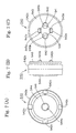
hydraulic tensioner 500, thecheck valve unit 540 comprises a syntheticresin ball guide 542, aball seat 544 attached to the ball guide, acheck ball 541 disposed in opposed relationship to the valve seat and guided by theball guide 542, a check ball-biasing spring 545, which biases thecheck ball 541 toward the valve seat, and a disc-shaped retainer 543, which limits the extent to which thecheck ball 541 can move away from theball seat 544. As shown in FIGs. 7(A), 7(B) and 7 (C), twoprotrusions 542a are provided on opposite sides of the center of theball guide 542 on the high pressure chamber side thereof. An outercircumferential tongue 542b is provided on the ball guide for pressing against the wall of the plunger accommodating hole, adjacent the bottom end thereof. Four crimpedprotrusions 542c are provided at four locations on the outer circumference of the ball guide at the inlet side thereof. Theretainer 543 is provided withholes 543a for receiving theprotrusions 542a. Anoil communication hole 543b is provided in theretainer 543. Avalve seat 544a is provided on theball seat 544 for abutting engagement with thecheck ball 541, and the ball seat is held in place by the four crimpedprotrusions 542c. The twoprotrusions 542a, which hold the retainer to the ball guide, are inserted intoholes 543a of theretainer 543, and then crimped in order to fix the retainer to the ball guide. - Several problems are encountered in the assembly and use of the check valve structure of FIGs. 6 - 7(C). The parts of the
protrusions 542a that extend throughholes 543a are liable to become chipped. The width of the crimped portions of theprotrusions 542a is limited. The end of the plunger-biasingspring 530 is not fixed relative to the disc-shaped retainer 543. Furthermore, it is difficult to position theholes 543a in theretainer 543 so that they receiveprotrusions 542a of theball guide 542. Finally, since theball seat 544 is fixed by the four crimpedprotrusions 542c provided on the outer circumference of theball guide 542, theprotrusions 542c are liable to become chipped. The widths of these protrusions are also limited. - Object of this invention is to provide a hydraulic tensioner which can be assembled easily, and in which the check valve unit can be readily assembled and incorporated into the tensioner easily and securely.
- The hydraulic tensioner in accordance with the invention comprises a housing having a plunger-accommodating hole formed therein, and a plunger. The plunger-accommodating hole has an opening at one end thereof and a bottom portion at the opposite end thereof. A plunger is slidable in the plunger-accommodating hole and protrudes through the opening in order to apply tension to a chain, a belt, or a similar traveling, flexible power transmission medium. The plunger and the housing together form a high-pressure oil chamber. The tensioner also includes a plunger-biasing spring, accommodated in the high pressure oil chamber. The spring biases the plunger in a protruding direction. A check valve unit is incorporated into the housing, within the plunger-accommodating hole and adjacent the bottom portion thereof. The check valve unit is arranged to allow flow of oil into the high-pressure oil chamber, and to prevent reverse flow of oil. The check valve unit has an outlet side facing the high pressure oil chamber and an opposite inflow side.
- The check valve unit comprises a check ball, a ball seat on which the check ball can be seated to block reverse flow of oil out of the high pressure oil chamber, a ball guide in which the check ball is freely movable toward and away from the ball seat, and a disc-shaped retainer holding the check ball in the ball guide while allowing movement of the check ball within the ball guide toward and away from the ball seat. The disc-shaped retainer has a surface facing the high pressure oil chamber. This surface has an annular peripheral region, and the ball guide has an annular portion on its high pressure oil chamber side. A part of the annular portion surrounds the disc-shaped retainer and a part of the annular portion is crimped over substantially the entirety of the annular peripheral region of the disc-shaped retainer.
- In a preferred embodiment, the annular portion of the ball guide forms a recess, and an end portion of the plunger-biasing spring extends into the recess, bears axially against the disc-shaped retainer, and is engaged with the annular portion of the ball guide and held thereby against radial movement.
- In the preferred embodiment, the ball seat also has an annular peripheral region and is fixed to the ball guide by an annular crimped portion of he ball guide on the inflow side thereof. This crimped portion is crimped over substantially the entirety of the annular peripheral region of said ball seat.
- The hydraulic tensioner of the invention maintains proper tension in a chain, a belt, or other traveling flexible power transmission medium in the same manner as a conventional hydraulic tensioner. However the tensioner exhibits a number of significant advantages over the conventional tensioner.
- The disc-shaped retainer is fixed to the ball guide by crimping the ball guide over an annular region that extends substantially entirely around the periphery of the retainer. Accordingly, in contrast with the tensioner shown in FIGs. 6 and 7, in the tensioner according to the invention, the crimped portion of the ball guide provides for a stronger check valve unit, and allows the check valve unit to be assembled without careful positioning of the retainer relative to the ball guide. Furthermore, because the retainer is more securely attached to the ball guide, the check valve unit can be incorporated into the bottom portion of the plunger-accommodating hole without the risk of detachment of the retainer from the ball guide.
- An additional advantage afforded by the invention is that the annular portion of the ball guide can form a recess for receiving and reliably positioning an end portion of the plunger-biasing spring, thereby avoiding wear and contact noise which would otherwise result from abnormal contact between the rear end portion of the plunger and the plunger-biasing spring.
- A further advantage is afforded where the ball seat is fixed to the ball guide by an annular crimped portion of he ball guide on the inflow side thereof, and the crimped portion is crimped over substantially the entirety of an annular peripheral region of the ball seat. With the ball seat fixed to the ball guide in this manner, the check valve unit can be installed at the bottom portion of the plunger-accommodating hole, without the risk of detachment of the ball seat from the guide.
- The invention will now be described in detail with reference to the accompanying drawings, in which:
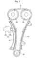
- FIG. 1 is a schematic elevational view of the timing drive of a dual overhead cam internal combustion engine, in which a hydraulic tensioner in accordance with the invention is used to maintain tension in a timing chain,
- FIG. 2 is a cross-sectional view of a hydraulic tensioner in accordance with a first embodiment of the invention,
- FIG. 3 is a partly broken-away perspective view of a check valve unit of the tensioner of FIG. 2,
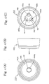
- FIGs. 4(A), 4(B) and 4(C) are respectively an inlet end view, a side view, and an outlet end view of the check valve unit of FIG. 3,
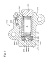
- FIG. 5 is a cross-sectional view of a hydraulic tensioner in accordance with a second embodiment of the invention,
- FIG. 6 FIG. 6 is a cross-sectional view of a related hydraulic tensioner, and
- FIGs. 7(A), 7(B) and 7(C) are respectively an inlet end view, a side view, and an outlet end view of the check valve unit of FIG. 6.
-
- The ball guide of the check valve unit may be composed of a synthetic resin or metal. However, it is preferably composed of synthetic resin so that crimping can be carried out by the application of heat, and assembly of the check valve unit can be carried out quickly and easily.
- As shown in FIGs. 1 and 2, a
hydraulic tensioner 100, in accordance with a first embodiment of the invention, is attached to an engine block adjacent the slack side of a timing chain C, which is in mesh with a drive sprocket S1 rotated by a crankshaft of an engine and driven sprockets S2 on valve-operating camshafts. Aplunger 120 protrudes through an opening of a cylindrical plunger-accommodatinghole 111 in atensioner housing 110, and applies tension to the slack side of the chain C through a pivoted lever L1 by pressing against a back surface of the lever at a location remote from the lever's pivot axis. A fixed guide L2 guides the travel of the timing chain C on the tension side thereof. Arrows in FIG. 1 indicate the directions of rotation of the sprockets and the direction of movement of the chain C. - The exterior of the
plunger 120 is cylindrical, and the plunger fits slidably in the plunger-accommodating hole 111. A high pressure oil chamber R is formed by theplunger 120 and the plunger-accommodatinghole 111. Acoil spring 130, serving as a plunger biasing spring, is accommodated within chamber R, and biases theplunger 120 in the protruding direction. - As shown in FIG. 2, a
check valve unit 140 is incorporated into the tensioner at the bottom of the plunger-accommodatinghole 111. The check valve unit allows oil, supplied from the engine through a passage (not shown), to flow into the high pressure chamber R, but blocks reverse flow of oil. - The
check valve unit 140 is an assembly comprising acheck ball 141, a syntheticresin ball guide 142, which envelopes the check ball and in which thecheck ball 141 is freely movable, a disc-shapedretainer 143 on the high pressure oil chamber side of theball guide 142 for maintaining thecheck ball 141 in theball guide 142, and ametal ball seat 144, fixed to the ball guide 142 on the inflow side. The ball is engageable with the seat to block reverse flow of oil out of the high pressure oil chamber R. - The disc-shaped
retainer 143 is fixed to theball guide 142 by crimping a portion of the ball guide over the retainer. Crimping a portion of the ball guide over the retainer in this manner provides a stronger assembly than in the case of thehydraulic tensioner 500 shown in FIGs. 6 - 7C. When thecheck valve unit 140 is incorporated into the plunger-accommodatinghole 111, there is little risk of detachment of theretainer 143 from the ball guide. As shown in FIGs. 3 and 4(A), an outercircumferential tongue 142b is provided on the ball guide for pressing against the cylindrical side wall of the plunger-accommodatinghole 111 in order to secure the check valve unit in place at the bottom of the plunger-accommodating hole.Oil communication holes 143a are bored in theretainer 143, as shown in FIGs. 3 and 4 (C). - A step-shaped
recess 143b is formed by the portion of the ball guide that is crimped over the retainer disc. This recess serves as a spring-positioning mounting recess, receiving a rear end of the plunger-biasingspring 130. Thus, the spring abuts theretainer 143 axially, and is reliably held against radial movement by engagement with the annular side wall of therecess 143b. By holding the end of the plunger-biasingspring 130 against radial displacement, the recess prevents wear and contact noise due to abnormal contact between the rear end of theplunger 120 and the spring. - The
ball seat 144 is also fixed to the inflow side theball guide 142 by an annular portion crimped over substantially the entirety of an annular peripheral region of the ball seat. Accordingly, the assembledcheck valve unit 140 can be incorporated into the bottom portion of the plunger-accommodatinghole 111 without the risk of detachment of theball seat 144 from the ball guide. - Because the
ball guide 142 is used in the high temperature environment of an engine, the ball guide is preferably composed of a polyamide resin such as nylon 46, nylon 66, glass fiber-reinforced nylon or the like. Crimping is carried out by the application of heat, to soften the resin, and the crimped portions of the ball guide exhibit excellent shape retention. - The
retainer 143, which maintains thecheck ball 141 within theball guide 142 and at the same time is in abutting engagement with the rear end of the plunger-biasingspring 130, is preferably made of metal. - The
check ball 141 may be composed of metal, ceramic, a synthetic resin, or the like, and has a diameter such that it can moved freely toward and away from the ball seat in the syntheticresin ball guide 142, its movement being limited by the ball seat and the retainer, respectively. - In the operation of the tensioner, the high pressure oil chamber R is always filled with oil supplied from the outside through the
check valve unit 140 by an oil pump or the like. When the timing chain C loosens, theplunger 120, which is continuously biased in the protruding direction by the plunger-biasingspring 130, takes up slack in the chain. As the plunger moves in the protruding direction, the oil chamber R expands, and oil flows into the chamber through thecheck valve unit 140. - When the
plunger 120 is pressed in the retracting direction by an impact force exerted by the timing chain C, the pressure of the oil in chamber R is increased, and thecheck ball 141 is pushed against theball seat 144. Consequently, reverse flow of oil from the high pressure oil chamber R through theoil passage 144a of theball seat 144 is blocked. As a result, the oil pressure in chamber R is further increased, and oil leaks through a slight clearance between the outer circumferential surface of theplunger 120 and the inner circumferential surface of the plunger-accommodatinghole 111, and is discharged to the exterior of thetensioner housing 110. Consequently, vibration of theplunger 120 due to the impact force, which acts on theplunger 120 is quickly damped by flow resistance due to the viscosity of the oil. - As described above, in the
hydraulic tensioner 100, since the disc-shapedretainer 143 is fixed to the high pressure oil chamber side of theball guide 142 around substantially its entire circumference, theretainer 143 and the ball guide 142 can be easily and securely assembled without the need for careful positioning of theretainer 143 relative to theball guide 142. Furthermore, the retainer and theplunger biasing spring 130 can be reliably positioned and assembled. Moreover, since theball seat 144 is fixed to the inflow side of theball guide 142 by crimping about substantially the entire outer circumference of theball guide 142, thecheck valve unit 140 can be easily incorporated into the bottom portion of the plunger-accommodatinghole 111 without detachment of the ball seat from the ball guide. - The
hydraulic tensioner 200, shown in FIG. 5, is also mounted on an engine body in the same manner astensioner 100.Tensioner 200 is different fromtensioner 100 in that it includes a ratchet mechanism in which retracting movement of theplunger 220 is blocked by engagement between arack 222 formed on theplunger 220, and apawl 250 pivoted on thetensioner housing 210. A ratchet-biasing spring urges theratchet pawl 250 toward therack 222. Other features of thetensioner 200 are the same as those oftensioner 100. Therefore, elements oftensioner 200 that correspond to elements oftensioner 100 in theseries 100 to 144 are denoted by corresponding reference numerals in theseries 200 to 244. - In the
check valve unit 240, a disc-shapedretainer 243 is fixed to aball guide 242 by crimping of a portion of the ball guide 242 over substantially the entirety of an annular circumferential area on the high pressure oil chamber side of theretainer 243. Thus, thecheck valve unit 240 is strongly assembled and the length of the crimped region is significantly greater than in the case of the check valve unit in the tensioner of FIGs. 6 - 7(C). Detachment of theretainer 243 from theball guide 242 in the process of installation of thecheck valve unit 240 in thetensioner housing 210 is reliably prevented. - As in the case of the check valve unit of FIGs. 2 - 4(C), a step-shaped recess is formed by the crimped part of the ball guide for receiving and positioning the rear end of the plunger-biasing spring. This spring positioning recess avoids wear and contact noise due to abnormal contact between the rear end of the
plunger 220 and the plunger-biasingspring 230. - The
ball seat 244 is fixed to the ball guide 242 on the inflow side by crimping around substantially the entire circumference of theball seat 244. Accordingly, thecheck valve unit 240 can be reliably incorporated into the bottom portion of the plunger-accommodatinghole 211, with little risk of detachment of theball seat 244 from theball guide 242. - The
retainer 243 and the ball guide 242 can be easily and securely assembled without special efforts to position theretainer 243 and the ball guide 242 relative to each other. Moreover, the plunger-biasingspring 230 is reliably positioned relative to theball guide 242 during assembly of the tensioner. Furthermore, since theball seat 244 is fixed to theball guide 242 by crimping around substantially its entire circumference on the inflow side of the check ball, thecheck valve unit 240 can be easily and securely incorporated into the bottom portion of the plunger-accommodatinghole 211 without detachment of theball seat 244 from theball guide 242. -
- 100, 200
- hydraulic tensioner
- 110, 210
- housing
- 111, 211
- plunger-accommodating hole
- 120, 220
- plunger
- 130,
- 230 spring
- 140, 240
- check valve unit
- 141
- check ball
- 142, 242
- ball guide
- 142b
- outer circumferential tongue
- 143, 243
- retainer
- 143a
- oil communication hole
- 143b
- recess
- 144,
- 244 ball seat
- 144a
- oil passage
- 222
- rack
- 250
- pawl
- C
- chain
- L1
- pivoted lever
- L2
- fixed guide
- R
- high pressure oil chamber
- S1
- drive sprocket
- S2
- driven sprocket
Claims (3)
- Hydraulic tensioner comprising:wherein the check valve unit (140; 240) comprises a check ball (141), a ball seat (144; 244) on which the check ball (141) can be seated to block reverse flow of oil out of the high pressure oil chamber (R), a ball guide (142; 242) in which the check ball (141) is freely movable toward and away from the ball seat (144; 244), and a disc-shaped retainer (143; 243) holding the check ball (141) in the ball guide (142; 242) while allowing movement of the check ball (141) within the ball guide (142; 242) toward and away from the ball seat (144; 244), the disc-shaped retainer (143; 243) having a surface facing the high pressure oil chamber (R), and the surface having an annular peripheral region, the ball guide (142; 242) having an annular portion on the high pressure oil chamber side of the ball guide (142; 242), a part of the annular portion surrounding the disc-shaped retainer (143; 243) and a part of the annular portion being crimped over substantially the entirety of the annular peripheral region of the disc-shaped retainer (143; 243).a housing (110; 210) having a plunger-accommodating hole (111; 211) formed therein, the plunger-accommodating hole (111; 211) having an opening at one end thereof and a bottom portion at the opposite end thereof,a plunger (120; 220) slidable in the plunger-accommodating hole (111; 211) and protruding therefrom, through the opening, for applying tension to a traveling flexible power transmission medium, the plunger (120; 220) and the housing (110; 210) together forming a high-pressure oil chamber (R),a plunger-biasing spring (130; 230), accommodated in the high pressure oil chamber (R), the spring (130; 230) biasing the plunger (120; 220) in a protruding direction, anda check valve unit (140; 240) incorporated into the housing (110; 210), within the plunger-accommodating hole (111; 211) and adjacent the bottom portion thereof, the check valve unit (140; 240) being arranged to allow flow of oil into the high-pressure oil chamber (R), and to prevent reverse flow of oil, the check valve unit (140; 240) having an outlet side facing the high pressure oil chamber (R) and an opposite inflow side,
- Hydraulic tensioner according to claim 1, in which the annular portion of the ball guide (142; 242) forms a recess (143b), and in which an end portion of the plunger-biasing spring (130; 230) extends into the recess (143b), bears axially against the disc-shaped retainer (143; 243), and is engaged with the annular portion of the ball guide (142; 242) and held thereby against radial movement.
- Hydraulic tensioner according to claim 1 or 2, in which the ball seat (144; 244) has an annular peripheral region and is fixed to the ball guide (142; 242) by an annular crimped portion of the ball guide (142; 242) on the inflow side thereof, the crimped portion being crimped over substantially the entirety of the annular peripheral region of the ball seat (144; 244).
Applications Claiming Priority (2)
| Application Number | Priority Date | Filing Date | Title |
|---|---|---|---|
| JP2004115870A JP3841355B6 (en) | 2004-04-09 | Hydraulic tensioner | |
| JP2004115870 | 2004-04-09 |
Publications (3)
| Publication Number | Publication Date |
|---|---|
| EP1584843A2 true EP1584843A2 (en) | 2005-10-12 |
| EP1584843A3 EP1584843A3 (en) | 2007-05-23 |
| EP1584843B1 EP1584843B1 (en) | 2010-04-14 |
Family
ID=34909552
Family Applications (1)
| Application Number | Title | Priority Date | Filing Date |
|---|---|---|---|
| EP05005820A Expired - Lifetime EP1584843B1 (en) | 2004-04-09 | 2005-03-17 | Hydraulic tensioner |
Country Status (4)
| Country | Link |
|---|---|
| US (1) | US7641575B2 (en) |
| EP (1) | EP1584843B1 (en) |
| CN (1) | CN1680734B (en) |
| DE (1) | DE602005020545D1 (en) |
Cited By (4)
| Publication number | Priority date | Publication date | Assignee | Title |
|---|---|---|---|---|
| WO2007059394A1 (en) | 2005-11-14 | 2007-05-24 | Borgwarner Inc | Hydraulic check valve assembly |
| DE102007061298A1 (en) | 2007-02-02 | 2008-08-07 | Tsubakimoto Chain Co. | Hydraulic tensioning device |
| DE102009008804A1 (en) | 2008-02-18 | 2009-08-20 | Tsubakimoto Chain Co., Nakanoshima | Hydraulic tensioner |
| DE102009008803A1 (en) | 2008-02-18 | 2009-08-20 | Tsubakimoto Chain Co., Nakanoshima | Hydraulic tensioner |
Families Citing this family (24)
| Publication number | Priority date | Publication date | Assignee | Title |
|---|---|---|---|---|
| JP4180487B2 (en) * | 2003-10-28 | 2008-11-12 | 株式会社椿本チエイン | Hydraulic tensioner |
| JP3933634B2 (en) * | 2004-03-08 | 2007-06-20 | 株式会社椿本チエイン | Hydraulic tensioner |
| JP3642526B1 (en) * | 2004-05-14 | 2005-04-27 | 株式会社椿本チエイン | Hydraulic tensioner |
| JP3642527B1 (en) * | 2004-05-31 | 2005-04-27 | 株式会社椿本チエイン | Hydraulic tensioner |
| JP3962052B2 (en) * | 2004-11-02 | 2007-08-22 | 株式会社椿本チエイン | Hydraulic tensioner |
| JP2007040440A (en) * | 2005-08-03 | 2007-02-15 | Tsubakimoto Chain Co | Plastic hydraulic tensioner |
| DE102005056506A1 (en) * | 2005-11-17 | 2007-05-24 | Weber Technology Ag | tensioning assembly |
| GB0607775D0 (en) * | 2006-04-20 | 2006-05-31 | Renold Plc | Tensioner for a chain or belt |
| CN101680515B (en) * | 2007-05-01 | 2012-09-05 | 利滕斯汽车合伙公司 | Wear compensated tensioner |
| JP4611394B2 (en) * | 2008-02-18 | 2011-01-12 | 株式会社椿本チエイン | Hydraulic tensioner |
| WO2012106093A2 (en) * | 2011-02-04 | 2012-08-09 | Borgwarner Inc. | High flow and quick response check valve for hydraulic tensioner |
| CN103348168B (en) * | 2011-02-28 | 2015-04-22 | 博格华纳公司 | Variable flow check valve for hydraulic tensioner |
| JP2013204690A (en) * | 2012-03-28 | 2013-10-07 | Tsubakimoto Chain Co | Hydraulic tensioner |
| JP2013204767A (en) * | 2012-03-29 | 2013-10-07 | Ntn Corp | Hydraulic auto-tensioner |
| US10006524B2 (en) * | 2013-12-03 | 2018-06-26 | Borgwarner Inc. | Integrated pressure relief valve for hydraulic tensioner |
| JP6757744B2 (en) * | 2015-05-14 | 2020-09-23 | ボーグワーナー インコーポレーテッド | Integrated disc check valve in hydraulic tensioners with weighed backflow |
| JP6523844B2 (en) * | 2015-07-18 | 2019-06-05 | ボーグワーナー インコーポレーテッド | Integrated check relief valve |
| US10781892B2 (en) | 2015-07-31 | 2020-09-22 | Borgwarner Inc. | Press-fit check valve for a hydraulic tensioner reservoir with metered backflow |
| DE102017103534A1 (en) * | 2017-02-21 | 2018-08-23 | Iwis Motorsysteme Gmbh & Co. Kg | Valve unit with carrier plate and valve body |
| DE102018114200A1 (en) | 2017-06-15 | 2018-12-20 | Borgwarner Inc. | Clamp with check valve with controllable stiffness |
| CN109654183A (en) * | 2017-10-12 | 2019-04-19 | 博格华纳公司 | Hydraulic tensioner with adjustable check-valves |
| JP7495348B2 (en) | 2018-02-26 | 2024-06-04 | ボーグワーナー インコーポレーテッド | Variable Force Tensioner with Internal Reservoir Technology Primary Bore |
| JP2020101279A (en) | 2018-12-21 | 2020-07-02 | ボーグワーナー インコーポレーテッド | Tensioner with piston containing internal check valve |
| US12181046B2 (en) | 2021-04-13 | 2024-12-31 | Borgwarner Inc. | Variable stiffness function through a check valve in a hydraulic |
Citations (1)
| Publication number | Priority date | Publication date | Assignee | Title |
|---|---|---|---|---|
| JP4084953B2 (en) | 2002-04-18 | 2008-04-30 | 日清紡績株式会社 | Biodegradable plastic composition, molded product thereof, and biodegradation rate control method |
Family Cites Families (31)
| Publication number | Priority date | Publication date | Assignee | Title |
|---|---|---|---|---|
| DE2021283A1 (en) * | 1970-04-30 | 1972-02-03 | Danfoss As | Process for the manufacture of an insert check valve and a check valve manufactured according to this |
| GB2065265B (en) | 1979-12-19 | 1983-09-01 | Kubota Ltd | Chain tensioner |
| DE3636918A1 (en) * | 1986-10-30 | 1988-05-05 | Schaeffler Waelzlager Kg | CHAIN TENSIONER |
| JP2821248B2 (en) | 1990-07-16 | 1998-11-05 | 日本電気アイシーマイコンシステム株式会社 | Discrimination circuit |
| JP2563656B2 (en) | 1990-07-30 | 1996-12-11 | 松下電器産業株式会社 | Ultrasonic Doppler imaging device |
| JPH0484953U (en) * | 1990-11-30 | 1992-07-23 | ||
| JPH0649868A (en) | 1992-07-27 | 1994-02-22 | Hitachi Constr Mach Co Ltd | Alarm sound device of construction machine |
| JPH0649868U (en) * | 1992-12-11 | 1994-07-08 | カヤバ工業株式会社 | Check valve |
| DE4415960A1 (en) * | 1994-05-06 | 1995-11-09 | Schaeffler Waelzlager Kg | Transport lock for a chain tensioner |
| JP3267077B2 (en) | 1994-12-12 | 2002-03-18 | トヨタ自動車株式会社 | Check valve |
| US5643117A (en) | 1995-12-08 | 1997-07-01 | Borg-Warner Automotive, Inc. | Hydraulic tensioner with check valve vent |
| DE19622123A1 (en) | 1996-06-01 | 1997-12-04 | Schaeffler Waelzlager Kg | No=return valve |
| US5988580A (en) * | 1996-12-13 | 1999-11-23 | King Of Fans, Inc. | Aesthetic components for ceiling fans |
| US5707309A (en) * | 1997-01-23 | 1998-01-13 | Borg-Warner Automotive, Inc. | Hydraulic tensioner with modular inlet check valve with pressure relief |
| DE19739904A1 (en) * | 1997-09-11 | 1999-03-18 | Bosch Gmbh Robert | Check valve, especially for a piston pump |
| US5993341A (en) | 1997-11-25 | 1999-11-30 | Borg-Warner Automotive, Inc. | Hydraulic tensioner with a position actuated check valve assembly |
| JPH11336855A (en) | 1998-05-27 | 1999-12-07 | Tsubakimoto Chain Co | Hydraulic tensioner |
| EP0985849B1 (en) * | 1998-09-09 | 2003-08-20 | Morse Tec Europe S.r.l. | Belt or chain tensioning device with piston having a plurality of reciprocally movable elements |
| US6165090A (en) * | 1998-09-21 | 2000-12-26 | Borgwarner Inc. | Hydraulic tensioner with vent formed with stacked plates |
| US6139454A (en) | 1998-09-21 | 2000-10-31 | Borgwarner Inc. | Hydraulic tensioner with plastic cap check valve or vent |
| JP2000179721A (en) | 1998-12-17 | 2000-06-27 | Rhythm Corp | Check valve |
| JP3415536B2 (en) * | 2000-01-21 | 2003-06-09 | 株式会社椿本チエイン | Ratchet type tensioner equipped with a mechanism for retaining and releasing the plunger |
| DE60004832T2 (en) * | 2000-09-13 | 2004-06-17 | Morse Tec Europe S.R.L. | Hydraulic chain tensioner with backstop for the piston |
| JP3710124B2 (en) * | 2001-01-10 | 2005-10-26 | 株式会社椿本チエイン | Hydraulic tensioner |
| JP3712951B2 (en) * | 2001-03-27 | 2005-11-02 | 株式会社椿本チエイン | Hydraulic plastic tensioner |
| JP3322400B1 (en) * | 2002-01-11 | 2002-09-09 | 株式会社椿本チエイン | Ratchet type hydraulic tensioner |
| DE10251042A1 (en) * | 2002-11-02 | 2004-05-19 | Daimlerchrysler Ag | Motor vehicle drive equipment for use with automatic gears has oil pump for gear system driven solely by electric motor |
| JP3649229B2 (en) * | 2003-06-30 | 2005-05-18 | 株式会社椿本チエイン | Hydraulic tensioner |
| JP3642526B1 (en) * | 2004-05-14 | 2005-04-27 | 株式会社椿本チエイン | Hydraulic tensioner |
| JP3642527B1 (en) | 2004-05-31 | 2005-04-27 | 株式会社椿本チエイン | Hydraulic tensioner |
| JP3962052B2 (en) * | 2004-11-02 | 2007-08-22 | 株式会社椿本チエイン | Hydraulic tensioner |
-
2005
- 2005-01-19 US US11/039,661 patent/US7641575B2/en active Active
- 2005-03-17 DE DE602005020545T patent/DE602005020545D1/en not_active Expired - Lifetime
- 2005-03-17 EP EP05005820A patent/EP1584843B1/en not_active Expired - Lifetime
- 2005-03-31 CN CN200510062966.9A patent/CN1680734B/en not_active Expired - Lifetime
Patent Citations (1)
| Publication number | Priority date | Publication date | Assignee | Title |
|---|---|---|---|---|
| JP4084953B2 (en) | 2002-04-18 | 2008-04-30 | 日清紡績株式会社 | Biodegradable plastic composition, molded product thereof, and biodegradation rate control method |
Cited By (4)
| Publication number | Priority date | Publication date | Assignee | Title |
|---|---|---|---|---|
| WO2007059394A1 (en) | 2005-11-14 | 2007-05-24 | Borgwarner Inc | Hydraulic check valve assembly |
| DE102007061298A1 (en) | 2007-02-02 | 2008-08-07 | Tsubakimoto Chain Co. | Hydraulic tensioning device |
| DE102009008804A1 (en) | 2008-02-18 | 2009-08-20 | Tsubakimoto Chain Co., Nakanoshima | Hydraulic tensioner |
| DE102009008803A1 (en) | 2008-02-18 | 2009-08-20 | Tsubakimoto Chain Co., Nakanoshima | Hydraulic tensioner |
Also Published As
| Publication number | Publication date |
|---|---|
| US7641575B2 (en) | 2010-01-05 |
| JP3841355B2 (en) | 2006-11-01 |
| US20050227799A1 (en) | 2005-10-13 |
| DE602005020545D1 (en) | 2010-05-27 |
| CN1680734A (en) | 2005-10-12 |
| CN1680734B (en) | 2011-07-06 |
| EP1584843A3 (en) | 2007-05-23 |
| JP2005299783A (en) | 2005-10-27 |
| EP1584843B1 (en) | 2010-04-14 |
Similar Documents
| Publication | Publication Date | Title |
|---|---|---|
| EP1584843B1 (en) | Hydraulic tensioner | |
| EP1602857B1 (en) | Hydraulic tensioner | |
| EP1493944B1 (en) | Hydraulic tensioner | |
| US6093123A (en) | Integrated chain drive tensioner and sprocket assembly | |
| EP0989327B1 (en) | Hydraulic tensioner with external rack having backlash restriction | |
| EP2532923B1 (en) | Modular hydraulic tensioner with ratchet | |
| EP0989333B1 (en) | Hydraulic tensioner with a pawl-style external rack | |
| US7618339B2 (en) | Hydraulic tensioner with improved relief valve | |
| EP1596097B1 (en) | Hydraulic tensioner | |
| US20080261737A1 (en) | Hydraulic tensioner | |
| US8007384B2 (en) | Hydraulic tensioner | |
| US7468012B2 (en) | Ratchet type tensioner | |
| US7001295B2 (en) | Hydraulic tensioner | |
| EP1498580A2 (en) | Tensioner for a chain or belt | |
| US7427250B2 (en) | Ring type hydraulic tensioner | |
| EP1528286B1 (en) | Hydraulic tensioner | |
| GB2338046A (en) | Ratchet tensioner | |
| US20020098931A1 (en) | Ratchet-operated tensioner with pressure oil chamber | |
| JP4260189B2 (en) | Hydraulic tensioner | |
| EP1528287B1 (en) | Hydraulic tensioner | |
| EP1426657A2 (en) | A hydraulic tensioner | |
| JP3841355B6 (en) | Hydraulic tensioner |
Legal Events
| Date | Code | Title | Description |
|---|---|---|---|
| PUAI | Public reference made under article 153(3) epc to a published international application that has entered the european phase |
Free format text: ORIGINAL CODE: 0009012 |
|
| AK | Designated contracting states |
Kind code of ref document: A2 Designated state(s): AT BE BG CH CY CZ DE DK EE ES FI FR GB GR HU IE IS IT LI LT LU MC NL PL PT RO SE SI SK TR |
|
| AX | Request for extension of the european patent |
Extension state: AL BA HR LV MK YU |
|
| PUAL | Search report despatched |
Free format text: ORIGINAL CODE: 0009013 |
|
| AK | Designated contracting states |
Kind code of ref document: A3 Designated state(s): AT BE BG CH CY CZ DE DK EE ES FI FR GB GR HU IE IS IT LI LT LU MC NL PL PT RO SE SI SK TR |
|
| AX | Request for extension of the european patent |
Extension state: AL BA HR LV MK YU |
|
| 17P | Request for examination filed |
Effective date: 20070612 |
|
| AKX | Designation fees paid |
Designated state(s): DE FR GB |
|
| 17Q | First examination report despatched |
Effective date: 20090210 |
|
| GRAP | Despatch of communication of intention to grant a patent |
Free format text: ORIGINAL CODE: EPIDOSNIGR1 |
|
| GRAS | Grant fee paid |
Free format text: ORIGINAL CODE: EPIDOSNIGR3 |
|
| GRAA | (expected) grant |
Free format text: ORIGINAL CODE: 0009210 |
|
| RIN1 | Information on inventor provided before grant (corrected) |
Inventor name: YOSHIDA, OSAMU |
|
| AK | Designated contracting states |
Kind code of ref document: B1 Designated state(s): DE FR GB |
|
| REG | Reference to a national code |
Ref country code: GB Ref legal event code: FG4D |
|
| REF | Corresponds to: |
Ref document number: 602005020545 Country of ref document: DE Date of ref document: 20100527 Kind code of ref document: P |
|
| PLBE | No opposition filed within time limit |
Free format text: ORIGINAL CODE: 0009261 |
|
| STAA | Information on the status of an ep patent application or granted ep patent |
Free format text: STATUS: NO OPPOSITION FILED WITHIN TIME LIMIT |
|
| 26N | No opposition filed |
Effective date: 20110117 |
|
| GBPC | Gb: european patent ceased through non-payment of renewal fee |
Effective date: 20110317 |
|
| REG | Reference to a national code |
Ref country code: FR Ref legal event code: ST Effective date: 20111130 |
|
| PG25 | Lapsed in a contracting state [announced via postgrant information from national office to epo] |
Ref country code: FR Free format text: LAPSE BECAUSE OF NON-PAYMENT OF DUE FEES Effective date: 20110331 |
|
| PG25 | Lapsed in a contracting state [announced via postgrant information from national office to epo] |
Ref country code: GB Free format text: LAPSE BECAUSE OF NON-PAYMENT OF DUE FEES Effective date: 20110317 |
|
| PGFP | Annual fee paid to national office [announced via postgrant information from national office to epo] |
Ref country code: DE Payment date: 20240130 Year of fee payment: 20 |
|
| REG | Reference to a national code |
Ref country code: DE Ref legal event code: R071 Ref document number: 602005020545 Country of ref document: DE |