EP1584495A2 - Automatic detector device for a tyre assembling-disasssembling machine - Google Patents
Automatic detector device for a tyre assembling-disasssembling machine Download PDFInfo
- Publication number
- EP1584495A2 EP1584495A2 EP05007139A EP05007139A EP1584495A2 EP 1584495 A2 EP1584495 A2 EP 1584495A2 EP 05007139 A EP05007139 A EP 05007139A EP 05007139 A EP05007139 A EP 05007139A EP 1584495 A2 EP1584495 A2 EP 1584495A2
- Authority
- EP
- European Patent Office
- Prior art keywords
- detector device
- bead
- wheel
- roll
- releasing
- Prior art date
- Legal status (The legal status is an assumption and is not a legal conclusion. Google has not performed a legal analysis and makes no representation as to the accuracy of the status listed.)
- Granted
Links
Images




Classifications
-
- B—PERFORMING OPERATIONS; TRANSPORTING
- B60—VEHICLES IN GENERAL
- B60C—VEHICLE TYRES; TYRE INFLATION; TYRE CHANGING; CONNECTING VALVES TO INFLATABLE ELASTIC BODIES IN GENERAL; DEVICES OR ARRANGEMENTS RELATED TO TYRES
- B60C25/00—Apparatus or tools adapted for mounting, removing or inspecting tyres
- B60C25/01—Apparatus or tools adapted for mounting, removing or inspecting tyres for removing tyres from or mounting tyres on wheels
- B60C25/05—Machines
- B60C25/132—Machines for removing and mounting tyres
- B60C25/135—Machines for removing and mounting tyres having a tyre support or a tool, movable along wheel axis
- B60C25/138—Machines for removing and mounting tyres having a tyre support or a tool, movable along wheel axis with rotary motion of tool or tyre support
-
- B—PERFORMING OPERATIONS; TRANSPORTING
- B60—VEHICLES IN GENERAL
- B60C—VEHICLE TYRES; TYRE INFLATION; TYRE CHANGING; CONNECTING VALVES TO INFLATABLE ELASTIC BODIES IN GENERAL; DEVICES OR ARRANGEMENTS RELATED TO TYRES
- B60C25/00—Apparatus or tools adapted for mounting, removing or inspecting tyres
- B60C25/01—Apparatus or tools adapted for mounting, removing or inspecting tyres for removing tyres from or mounting tyres on wheels
- B60C25/05—Machines
- B60C25/0548—Machines equipped with sensing means, e.g. for positioning, measuring or controlling
- B60C25/0551—Machines equipped with sensing means, e.g. for positioning, measuring or controlling mechanical
Definitions
- the present invention relates to an automatic detector for tyre assembling-disassembling machines, particularly, but not exclusively, suitable for tyre assembling-disassembling machines using a pair of arms each carrying a tyre bead-releasing roll.
- tyre assembling-disassembling machines have already been proposed having one or more bead-releasing rolls, which are carried at the free end of a respective telescopic support arm, arranged on opposite sides with respect to a tyred wheel to be disassembled, and suitable for being pressed against the wheel tyre to simultaneously release the tyre bead at the two sides of the wheel, while allowing the tyred wheel to rotate around its axis of rotation.
- the operator In order to carry out a bead-releasing operation with a pair of bead-releasing rolls, the operator, while taking into account the size of the wheel rim, controls the pair of bead-releasing rolls so as to move them close to a respective edge of the wheel rim, by causing an extension or lengthening of their telescopic support arms.
- the operator When each bead-releasing roll reaches an abutting position against its respective rim edge, the operator also controls mutual approaching or "clamping" movement, of the two telescopic arms and thus of the bead-releasing rolls carried by them, while simultaneously setting in rotation the wheel the tyre bead of which is to be released.
- the edge of the two bead-releasing rolls should rest against its respective tyre side, while abutting against the rim edge of the tyred wheel.
- each bead-releasing roll after its positioning close to its respective edge of the wheel rim is thus a broken line roughly having a first length parallel to wheel axis of rotation, a second very short length inclined and directed towards the same axis, and a third length also parallel to the axis of the tyred wheel.
- a first solution was a tyre assembling-disassembling machine provided with cams arranged to control the bead-releasing rolls to follow a predetermined broken path. Such a solution, however, owing to the fact that the path is predetermined and fixed, cannot be adopted for all at present commercially available types of tyred wheel.
- a second and easier solution is to cause the bead-releasing rolls to follow an approaching path along an arched line in its respective lying plane containing both its respective telescopic arm and the tyred wheel axis of rotation, starting from the wheel rim edge towards the axis of rotation of the wheel.
- the bead-releasing rolls could start pressing onto a length of the tyre side rather than onto the bead, which, as it is known, is the most resistant portion of the tyre and thus with the risk of causing the tyre to break or to become permanently damaged.
- a further already suggested solution is that such a broken path is manually executed by an operator, thereby entrusting the success of the tyre bead-releasing operation to the skill and ability of the operator, who has to be highly trained.
- a last solution is to provide that the bead-releasing rolls, after contact with the tyre, press a spring and control a suitable detector in order to start the broken path.
- This solution has serious drawbacks in so far as the deformation calibration of the detector is concerned.
- a bead-releasing roll when the same is in contact with the tyre side, fails to control the detector which results in no control for starting the broken path being generated.
- the two rolls then continue their approaching movement, while further pressure is applied onto the tyre side, which can sometimes results in the tyre been damage or even cut.
- each bead-releasing roll could control in advance the detector, even before starting deformation of the tyre side, whereby a control to start the broken path is generated too early.
- each bead-releasing roll will be forced to slide onto the tyre side until it steps or passes over the wheel rim edge, which might results in both the tyre and the wheel rim being damaged, especially if the latter is made of a light alloy.
- the main object of the present invention is to provide an automatic detector device for a tyre assembling-disassembling machines that is suitable for eliminating or drastically reducing the above mentioned drawbacks.
- Another object of the present invention is to provide an automatic detector device which makes it possible also for a not highly skilled operator to release a tyre bead from a wheel rim edge, as the bead-releasing rolls are cause to follow an optimal bead-releasing path for each type of tyred wheel in a simple and fast manner.
- a further object of the present invention is to provide an automatic detector device for tyre assembling-disassembling machines that can be installed in any type of tyre assembling-disassembling machines provided with a pair of bead-releasing roll-carrying arms.
- an automatic detector device for a tyre assembling-disassembling machine having at least one rotatable support for a tyred wheel, the tyre bead of which is to be released from its wheel rim edge, at least one extendable-retractable bead-releasing roll-carrying arm, each arm supporting at least one respective bead-releasing roll and being located, in use, facing said tyred wheel, said detector device being characterized in that it comprises at least one sensor member movably supported at a respective bead-releasing roll, driving means for each sensor member, whereby it is movable between a rest position and a extended working position, and control means designed to act in response to control signals generated by said sensor member in said working position.
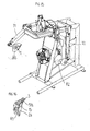
- a wheel assembling- disassembling machine has a bearing frame A with a base B from which a rear upright member C raises.
- base B Onto base B there is provided a rotatable assembly arranged to support a wheel rim or a tyred wheel, e.g. comprising a table, which can rotate about a substantially vertical axis of rotation and is provided with jaws to engage a wheel rim, or a gripping head having a number of expansion arms G and also mounted for rotation about a substantially vertical axis.
- a support and control assembly for a pair of overhangingly extending and retracting arms e.g. an upper and a lower telescopic arm T 1 and T 2 , which can expand and contract towards and away from gripping head G, each arm carrying a respective bead-releasing roll R 1 and R 2 at its free end.
- Arms T 1 and T 2 can be controlled, e.g. by means of a respective pneumatic jack M 1 and M 2 , so as to extend and retract, as well as to be moved close to, and away from one another along more or one vertical guides S by a pneumatic jack M 3 .
- Each telescopic arm T 1 and T 2 is provided with a braking or blocking device 10 of any suitable type, which is controlled by an electronic control unit 34, as will be further described below.
- Each bead-releasing roll R 1 and R 2 is usually frustoconical in shape and has a radiused edge at its greater base, and is idly mounted at the free front end of its respective roll-carrying arm T 1 and T 2 , its axis of rotation being inclined, e. g. of about 45 degrees, with respect to the longitudinal axis of its respective roll-carrying arm, and thus its radiused edge all around its greater base abuts, in use, against edge 7 of the wheel rim 8 of a tyred wheel 9 to be disassembled which is arranged on the rotatable table or grip head G, whereas its lateral surface rests against the tyre bead, as it is known to a person skilled in the art.
- an automatic detector is provided at each bead-releasing roll R 1 and R 2 .
- the operator By acting on suitable controls, not shown in detail in drawings, and generically comprising a control lever L, on which a control button for jack M 3 can be provided, the operator causes the two roll-carrying arms T 1 and T 2 to extend or retract depending upon the diameter of tyred wheel 9.
- the arms T 1 and T 2 are arranged aligned in the direction of the axis of rotation of the tyred wheel 9 at opposite sides with respect thereto, and their bead-releasing rolls R 1 and R 2 are each positioned close to a respective edge 7 of the wheel rim 8 of tyred wheel 9.
- An automatic detector device 1 is provided for each bead-releasing roll R 1 and R 2 and located on opposite side with respect to the frustoconical surface of its respective bead-releasing roll T 1 or T 2 .
- the overhanging end of each roll-carrying arm T 1 and T 2 typically carries a bracket 2, e.g. an U-shaped cross sectional bracket, to which a respective automatic detector device 1 is secured.
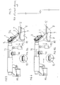
- An automatic detector device 1 comprises a sensor head 3 supported, e.g. secured by means of a screw 4, at the distal end of a rod-shaped member or finger 5a, which advantageously can be a piston-rod of a linear fluid-operated actuator 5.
- Linear actuator 5 also comprises a cylinder 19, in which a piston member 16 for controlling piston-rod 5a is slidingly mounted. Within cylinder 19 an helical return spring 21 is also provided, which at one end thereof abuts against piston member 16, whereas at its other end reacts against a bottom 20 of cylinder 19 (Figs. 9 to 11).
- a tubular member 14 is provided around to the rod-shaped member 5a, which assists in supporting sensor 3 at head thereof and has a longitudinal slit 17 designed to slidingly engage with an external projection 18 of cylinder 19, and thus tubular member 14 is guided during extension and retraction movements of the rod-shaped member or stem 5a and locked against amgular movements about its longitudinal axis.
- cylinder 19 At its end opposite to the end from which stem 5a extends, cylinder 19 is sealingly closed by means of a bottom 23 and is in fluid communication, e.g. through a transversal bore 24 and a conduit 25, with a suitable pressurized fluid (air) source 33 by means a shut-off electrovalve 32, which can be controlled in turn by an electronic control unit 34, such as an electronic board.
- cylinder 19 is housed in a supporting casing or box-like body 15. Near the end closed by the bottom 23, cylinder 19 is articulated to box-like body 15 by a pin 30, preferably carried by bracket 2, having its longitudinal axis extending transversely with respect to longitudinal axis of the cylinder, whereas at its other end away from pin 30 it is provided with a resilient return means, e.g. an helical spring 28, designed to act between cylinder 19 and internal wall of the box-like body 15 and advantageously held in position by means of a lug 27 projecting either from cylinder 19 or box-like body 15.
- a resilient return means e.g. an helical spring 28 designed to act between cylinder 19 and internal wall of the box-like body 15 and advantageously held in position by means of a lug 27 projecting either from cylinder 19 or box-like body 15.
- cylindrical body 19 is angularly displaceable about the transversal pin 30 between a rest position, e.g. with return spring 28 in a relaxed condition (Figs. 9 and 11), and a working position against the action of the return spring 28 (Fig. 10). Amplitude of angular movement of cylinder 19 has been indicated by angle ⁇ in Fig. 10.
- detector device 22 arranged to act in response to angular movement of cylinder 19 and thus of sensor 3 supported by it by means of stem 5a.
- detector device 22 can comprise a suitable button switch or micro-switch, e. g. having its body fixed to the inner wall of the box-like body 15 and its button 26 facing the cylinder 19, whereby the switch opens an electronic control circuit, preferably electrically connected to the control unit 34 of the electrovalve 32, when cylinder 19 angularly moves through angle ⁇ .
- stem 5a is not longer subjected to the thrust which has caused it to rotate through an angle ⁇ , as its return movement into cylinder 19 has started, and thus its disengagement from edge 7 of wheel-rim has begun. Owing to the return spring 29, cylinder 19 is caused to pivot about pin 30, thereby returning to its rest position as illustrated in Fig. 11.
- the operator while acting upon a suitable pedal S, energizes a motor, which causes the grip head G to rotate in order to carry out a complete bead-releasing operation all along the tyre, as in a conventional wheel assembling-disassembling machine.
- an automatic detector device 1 housed on a bead-releasing roll R 1 which has, in use, its stem 5a projecting from main body 15 and extending above and at the back of bead-releasing roll R 1 from which it is offset through a length "X", but at a different level "Y" in a direction parallel to the axis of rotation of the tyred wheel 9.
- sensor 3 is located outside the overall dimensions of its respective bead-releasing roll R 1 , thereby detecting the position of the edge 7 of wheel-rim 8 and starting then the above described sequence of operations.
- bead-releasing roll R 1 being located in a backward position by a length "X” and thus nearer to the side of tyre P by a distance "Y” than sensor 3, comes to rest onto the edge 7 of wheel-rim 8, thereby being ready to start the above mentioned sequence of operations.
- a bead-releasing roll R 1 of a tyre assembling-disassembling machine is illustrated, which is erroneously located with respect to the edge 7 of wheel-rim 8, e.g. owing to a wrong setting of the bead-releasing roll with respect to the diameter of the tyred wheel 9, with arrangement of roll-carrying arms T 1 and T 2 being thus altered.
- roll-carrying arm T 1 is located in such a way that its respective bead-releasing roll R 1 , while approaching tyred wheel 9, comes to rest onto the side of the wheel-rim 8 instead of abutting against the side of tyre P near the edge 7.
- sensor 3 cannot detect the presence of edge 7 of wheel-rim 8 and thus no signal is sent to control unit 34 for starting the bead-releasing steps.
- roll-carrying arm T 1 is located in such a way that the respective bead-releasing roll R 1 , while approaching tyred wheel 9, comes to rest onto the side of tyre P, although not in contact with the edge 7 of wheel-rim 8.. In this way, sensor 3 cannot detect the presence of the edge 7 of wheel-rim 8, and thus no signal is generated for starting the bead-releasing steps.
- Figures 12 and 13 illustrate an embodiment of an automatic detector device 1 comprising a not mechanical sensor 3, e.g. an optical or inductive capacitive sensor still housed at the distal end of the stem 5a of the linear actuator 5.
- a not mechanical sensor 3 e.g. an optical or inductive capacitive sensor still housed at the distal end of the stem 5a of the linear actuator 5.
- sensor 3 after the presence of edge 7 of wheel-rim 8 has been detected, e.g. through a laser or a difference in the magnetic field, sends a signal to the control unit 34, which in turn controls the electrovalve 32, which results in the stem 5a of the linear actuator 5 retracting into cylinder 19, with no angular movement about an articulation pin 30 and in the bead-releasing sequence of the tyred wheel 9 being started by wheel assembling-disassembling machine.
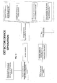
- FIG 14 shows a block diagram of the sequence of operations in a working cycle of a wheel assembling-disassembling machine using roll-carrying arms T 1 and T 2 provided with a respective automatic detector device 1 according to the present invention for bead-releasing tyres P.
- roll-carrier arms T 1 and T 2 are located by the operator aligned on opposite sides of a tyred wheel 9 by acting on the lever L, whereby stems 5a of linear actuators 5 are extended in their working position.
- Each above described operation can be carried out either automatically, through a suitable program written in the control unit 34, or in a totally manual manner to give the operator a less or a stricter control on the operations carried out. by the tyre assembling-disassembling machine.
- a control can be advantageously carried out on the resetting or failure to reset of stems 5a of the linear actuator 5, on the return into a rest position of the roll-carrying rolls T 1 and T 2 , on the clamping movement of the roll-carrying arms T 1 and T 2 , on the actuation of the jack M 1 , and the like.
- Figures 15 and 16 illustrate another embodiment of tyre assembling-disassembling machine, in which automatic detector devices 1 are located into an axial recess 26 of a respective bead-releasing roll R 1 and R 2 , so that in its rest position, i.e. with stem 5a being retracted into the cylinder 19, the automatic detector device 1 is fully contained within the overall dimensions of its respective bead-releasing roll R 1 , R 2 .
- sensor 3 can be a mechanical detector responsive to a predetermined stress level, an optical detector, a capacitive detector, or the like.
- Linear actuator 5 instead of being of fluid-operated type, can comprise e..g. an endless screw or a rack actuated by a reversible motor.
- the electrovalve 32 is replaced by a switch or the like.
Landscapes
- Engineering & Computer Science (AREA)
- Mechanical Engineering (AREA)
- Tires In General (AREA)
- Automatic Assembly (AREA)
- Moulds For Moulding Plastics Or The Like (AREA)
- Automobile Manufacture Line, Endless Track Vehicle, Trailer (AREA)
- Measuring Fluid Pressure (AREA)
Abstract
Description
- Moving backwards the stem of the
linear actuator 5 to its rest and protection position into thecylinder 19, - mutual slowed down approaching movement of roll-carrying arms T1
and T2 which results in a clamping action being exerted onto the
tyred wheel 9 by the hydraulic jack M3 in order to preventdamaging tyre 12, - energizing pneumatic jacks M1 and M2 to cause its respective roll-carrying
arm T1 or T2 to be extended, thereby moving forward the arm
in the direction of the axis of rotation of
tyred wheel 9, so that the combined action of two orthogonal movements, i. e. extension and mutual approaching movements, of roll-carrying arms T1 and T2 causes its respective bead-releasing roll R1, R2 to be inserted betweenedge 7 of the wheel-rim and the bead of tyre P until its rounded edge reaches theintermediate band 12 of wheel-rim 8 (Fig. 4), which has a smaller diameter than therespective edge 7, - de-energizing of jacks M1 and M2, and
- simultaneous locking of roll-carrying arms T1 and T2 owing to coming
into action of a
respective brake 10, thereby locking each roll-carrying arm in the reached extended position before its respective bead-releasing roll has reached theband 12 of the wheel-rim 8 of thetyred wheel 9.
Claims (14)
- An automatic detector device for a tyre assembling-disassembling machine having at least one rotatable support (G) for a tyred wheel (9), the tyre bead of which is to be released from its wheel rim edge, at least one extendable-retractable bead-releasing roll-carrying arm (T1, T2) each arm supporting at least one respective bead-releasing roll (R1, R2) and being located, in use, facing said tyred wheel (9), said detector device (1) being characterized in that it comprises at least one sensor member (3) movably supported at a respective bead-releasing roll (R1, R2), driving means (5) for each sensor member (3), whereby it is movable between a rest position and a extended working position, and control means (34) designed to act in response to control signals generated by said sensor member (3) in said working position.
- A detector device as claimed in claim 1, characterized in that said driving means (5) comprises at least one linear actuator having a rod-shaped component (5a) designed to support a respective sensor member (3) and controlled by a respective linear actuator, thereby being moved between said extended working position and said backwards rest position.
- A detector device as claimed in claim 1 or 2, characterized in that it comprises a support member or casing (15) for said operation means (5).
- A detector device as claimed in claim 3, characterized in that said support member (15) is located at a respective bead-releasing roll (R1, R2).
- A detector device as claimed in any claim 1 to 4, characterized in that said sensor member (3) is a mechanical sensor.
- A detector device as claimed in claim 5, characterized in that it comprises articulation means (30) and resilient return means (28) between said support member or casing (15) and its respective driving means (5).
- A detector device as claimed in claim 5 or 6, characterized in that it comprises switch means (22) arranged to act in response to an angular movement between said support member (15) and said operation means (5) for sending signals to said electronic control unit (34).
- A detector device as claimed in any claim 1 to 4, characterized in that said sensor member (3) is an optic sensor.
- A detector device as claimed in any claim 1 to 4, characterized in that said sensor member is a capacitive or inductive sensor.
- A detector device as claimed in any previous claim, characterized in that said electronic control unit (34) is designed to receive at least one control signal from said sensor member (3), when the latter abuts against an edge (7) of wheel- rim of said tyred wheel (9).
- A detector device as claimed in any previous claim, characterized in that said electronic control unit (34) is designed to start an operation sequence comprising:return of said rod-shaped component (5a) in its rest position,controlling a composite movement comprising approaching movement of said roll-carrying arms (T1, T2) and advancement towards said axis of rotation,setting in rotation said rotating support (G) and locking said roll-carrying arms (T1, T2).
- A detector device as claimed in any previous claim, characterized in that said rod-shaped component (5a) of said linear actuator (5) is held in said extended working position by a control member (32).
- A detector device as claimed in claim 12, characterized in that said control member (32) is an electrovalve.
- A detector device as claimed in claim 12, characterized in that said control member (32) is a switch.
Applications Claiming Priority (2)
| Application Number | Priority Date | Filing Date | Title |
|---|---|---|---|
| ITVR20040055 | 2004-04-09 | ||
| IT000055A ITVR20040055A1 (en) | 2004-04-09 | 2004-04-09 | AUTOMATIC FEELER FOR TIRE MOUNTING MACHINES |
Publications (3)
| Publication Number | Publication Date |
|---|---|
| EP1584495A2 true EP1584495A2 (en) | 2005-10-12 |
| EP1584495A3 EP1584495A3 (en) | 2006-12-06 |
| EP1584495B1 EP1584495B1 (en) | 2008-05-21 |
Family
ID=34897836
Family Applications (1)
| Application Number | Title | Priority Date | Filing Date |
|---|---|---|---|
| EP05007139A Expired - Lifetime EP1584495B1 (en) | 2004-04-09 | 2005-04-01 | Automatic detector device for a tyre assembling-disasssembling machine |
Country Status (8)
| Country | Link |
|---|---|
| US (1) | US7188656B2 (en) |
| EP (1) | EP1584495B1 (en) |
| JP (1) | JP4784970B2 (en) |
| CN (1) | CN100586745C (en) |
| AT (1) | ATE396069T1 (en) |
| DE (1) | DE602005006874D1 (en) |
| ES (1) | ES2305933T3 (en) |
| IT (1) | ITVR20040055A1 (en) |
Cited By (13)
| Publication number | Priority date | Publication date | Assignee | Title |
|---|---|---|---|---|
| EP1995083A1 (en) | 2007-05-23 | 2008-11-26 | Snap-on Equipment Srl a unico socio. | Method of and apparatus for determining geometrical dimension of a vehicle wheel comprising optical sensors |
| EP2020594A1 (en) * | 2007-07-30 | 2009-02-04 | Snap-on Equipment Srl a unico socio. | Method of and apparatus for determining geometrical dimensions of a vehicle wheel |
| EP2042351A1 (en) | 2007-09-19 | 2009-04-01 | BUTLER ENGINEERING & MARKETING S.p.a. | A bead breaker roller head for a tire mounting-demounting machine |
| EP2090446A1 (en) | 2008-02-13 | 2009-08-19 | Butler Engineering & Marketing S.p.A. | Bead releasing device |
| ITMO20090130A1 (en) * | 2009-05-18 | 2010-11-19 | Teco Srl | TOOL FOR REMOVAL TIRE MACHINES |
| US8322007B2 (en) | 2009-03-12 | 2012-12-04 | Butler Engineering & Marketing S.P.A. | Load handling device |
| IT201900005728A1 (en) | 2019-04-12 | 2020-10-12 | Nexion Spa | TIRE CHANGING DEVICE |
| IT202100001238A1 (en) | 2021-01-25 | 2022-07-25 | Snap On Equip Srl Unico Socio | TIRE CHANGER APPARATUS |
| IT202100001235A1 (en) | 2021-01-25 | 2022-07-25 | Snap On Equip Srl Unico Socio | TIRE CHANGER EQUIPMENT WITH AUTOMATIC TILTING TOOL |
| IT202100013760A1 (en) * | 2021-05-26 | 2022-11-26 | M & B Eng S R L | DEVICE FOR ASSEMBLING/DISASSEMBLING TIRES |
| IT202100018722A1 (en) | 2021-07-16 | 2023-01-16 | Snap On Equip Srl Unico Socio | Tire changer |
| IT202200009740A1 (en) * | 2022-05-11 | 2023-11-11 | Sicam Srl | GROUP FOR THE TREATMENT OF TIRE WHEELS |
| US12172474B2 (en) | 2021-03-12 | 2024-12-24 | Vehicle Service Group Italy S.R.L. | Tire changer apparatus |
Families Citing this family (22)
| Publication number | Priority date | Publication date | Assignee | Title |
|---|---|---|---|---|
| US8284390B1 (en) | 2003-02-20 | 2012-10-09 | Hunter Engineering Company | Vehicle tire changing system with tool positioning sensor |
| DE102004040866A1 (en) * | 2004-08-23 | 2006-03-02 | Schenck Rotec Gmbh | Device and method for mounting a tire |
| US8365794B2 (en) * | 2005-01-18 | 2013-02-05 | Android Industries Llc | Inflation work station |
| USD614679S1 (en) * | 2006-04-26 | 2010-04-27 | Corghi S.P.A. | Tire dismounter |
| US8613303B1 (en) * | 2008-07-17 | 2013-12-24 | Hunter Engineering Company | Tire changing machine with force detection and control methods |
| US8770254B1 (en) * | 2008-07-17 | 2014-07-08 | Hunter Engineering Company | Tire changer with rotational position and tracking control |
| US8387675B1 (en) * | 2009-09-09 | 2013-03-05 | Hunter Engineering Company | Tire changing machine with automated tire bead pressing devices, controls and methods |
| ITVR20080050A1 (en) * | 2008-04-28 | 2009-10-29 | Butler Eng & Marketing | BREAKER GROUP FOR A TIRE CHANGER MACHINE |
| US9073394B1 (en) | 2008-07-17 | 2015-07-07 | Hunter Engineering Company | Tire changing machine with force detection and control methods |
| IT1391808B1 (en) * | 2008-10-31 | 2012-01-27 | Sicam Srl | MALE DISPENSER FOR THE ASSEMBLY AND DISASSEMBLY OF VEHICLE WHEELS |
| US8783326B1 (en) * | 2009-09-09 | 2014-07-22 | Hunter Engineering Company | Tire changing machine with automated tire bead pressing devices, controls and methods |
| IT1396147B1 (en) | 2009-11-05 | 2012-11-16 | Corghi Spa | EQUIPMENT AND METHOD FOR THE ASSEMBLY AND DISASSEMBLY OF TIRES ON AND FROM THEIR RESPECTIVE RIMS |
| USD636003S1 (en) * | 2010-08-16 | 2011-04-12 | Hunter Engineering Company | Vehicle wheel target mount assembly |
| US20120222823A1 (en) * | 2011-03-02 | 2012-09-06 | Onodani Machine Co., Ltd. | Tire mounting and demounting machine, tire mounting method and tire demounting method |
| US9950580B2 (en) * | 2012-01-31 | 2018-04-24 | Android Industries Llc | Bead seater apparatus and method for using the same |
| ITVR20130252A1 (en) * | 2013-11-22 | 2015-05-23 | Butler Engineering And Marketing S P A | DISASSEMBLY DEVICE FOR A WHEELED WHEEL, AS WELL AS THE MACHINE INCLUDING THIS DEVICE. |
| EP3501862B1 (en) * | 2014-05-30 | 2022-08-03 | Snap-on Equipment Srl a unico socio | Method for mounting and demounting a tyre to and from a wheel rim |
| US9517667B2 (en) * | 2014-05-30 | 2016-12-13 | Snap-On Equipment Srl A Unico Socio | Tire mounting tool assembly |
| EP2995476B1 (en) * | 2014-09-12 | 2017-11-08 | Giuliano Group S.p.A. | Operating head for removing and fitting wheel tyres for vehicles |
| CN113183691B (en) * | 2021-04-25 | 2022-06-03 | 长春汽车工业高等专科学校 | Portable automobile tire fast loading and unloading equipment |
| CN113442664A (en) * | 2021-05-31 | 2021-09-28 | 胡瑞 | Utilize magnetic pole plate to realize tire erection equipment of correction screw position |
| CN114801604B (en) * | 2022-04-15 | 2023-08-01 | 伺轮智能机器人(南京)有限公司 | Method and device for detecting separation state of tire and rim |
Family Cites Families (6)
| Publication number | Priority date | Publication date | Assignee | Title |
|---|---|---|---|---|
| DE2529343C3 (en) * | 1975-07-01 | 1981-07-09 | Gebr. Hofmann Gmbh & Co Kg Maschinenfabrik, 6100 Darmstadt | Device for assembling and dismantling motor vehicle tires, in particular for trucks |
| JP3414784B2 (en) * | 1993-03-17 | 2003-06-09 | 株式会社バンザイ | Tire mounting device |
| ITVR20010124A1 (en) * | 2001-11-22 | 2003-05-22 | Butler Enrineering & Marketing | Bead breaker head with nail for assembly / disassembly of a tire for tire changer machine. |
| US7355687B2 (en) * | 2003-02-20 | 2008-04-08 | Hunter Engineering Company | Method and apparatus for vehicle service system with imaging components |
| JP2004330860A (en) * | 2003-05-07 | 2004-11-25 | Onodani Kiko Kk | Tire attaching/detaching device and tire removing method |
| ITVR20030062A1 (en) * | 2003-05-19 | 2004-11-20 | Butler Eng & Marketing | MAINTENANCE EQUIPMENT OF A WHEELED WHEEL |
-
2004
- 2004-04-09 IT IT000055A patent/ITVR20040055A1/en unknown
-
2005
- 2005-04-01 DE DE602005006874T patent/DE602005006874D1/en not_active Expired - Lifetime
- 2005-04-01 EP EP05007139A patent/EP1584495B1/en not_active Expired - Lifetime
- 2005-04-01 ES ES05007139T patent/ES2305933T3/en not_active Expired - Lifetime
- 2005-04-01 AT AT05007139T patent/ATE396069T1/en not_active IP Right Cessation
- 2005-04-06 CN CN200510063194.0A patent/CN100586745C/en not_active Expired - Lifetime
- 2005-04-07 US US11/101,225 patent/US7188656B2/en not_active Expired - Lifetime
- 2005-04-08 JP JP2005112294A patent/JP4784970B2/en not_active Expired - Lifetime
Cited By (27)
| Publication number | Priority date | Publication date | Assignee | Title |
|---|---|---|---|---|
| EP1995083A1 (en) | 2007-05-23 | 2008-11-26 | Snap-on Equipment Srl a unico socio. | Method of and apparatus for determining geometrical dimension of a vehicle wheel comprising optical sensors |
| EP2332749A1 (en) * | 2007-05-23 | 2011-06-15 | Snap-on Equipment Srl a unico socio | Method of and apparatus for determining geometrical dimension of a vehicle wheel comprising optical sensors |
| EP2020594A1 (en) * | 2007-07-30 | 2009-02-04 | Snap-on Equipment Srl a unico socio. | Method of and apparatus for determining geometrical dimensions of a vehicle wheel |
| EP2042351A1 (en) | 2007-09-19 | 2009-04-01 | BUTLER ENGINEERING & MARKETING S.p.a. | A bead breaker roller head for a tire mounting-demounting machine |
| US7798196B2 (en) | 2007-09-19 | 2010-09-21 | Butler Engineering & Marketing S.P.A. | Bead breaker roller head for a tire mounting-demounting machine |
| CN101391565B (en) * | 2007-09-19 | 2012-04-18 | 巴特勒工程商用股份公司 | A bead breaker roller head for a tire mounting-demounting machine |
| EP2090446A1 (en) | 2008-02-13 | 2009-08-19 | Butler Engineering & Marketing S.p.A. | Bead releasing device |
| US8322007B2 (en) | 2009-03-12 | 2012-12-04 | Butler Engineering & Marketing S.P.A. | Load handling device |
| ITMO20090130A1 (en) * | 2009-05-18 | 2010-11-19 | Teco Srl | TOOL FOR REMOVAL TIRE MACHINES |
| EP2253487A1 (en) * | 2009-05-18 | 2010-11-24 | Teco S.R.L. | Tool for a tyre demounting machine |
| US8464775B2 (en) | 2009-05-18 | 2013-06-18 | Teco S.R.L. | Tool for tire uninstalling and installing machines |
| EP3722114A1 (en) | 2019-04-12 | 2020-10-14 | NEXION S.p.A. | Bead breaker tool for a tyre changing apparatus |
| US12337623B2 (en) | 2019-04-12 | 2025-06-24 | Nexion S.P.A. | Tyre changing apparatus |
| IT201900005728A1 (en) | 2019-04-12 | 2020-10-12 | Nexion Spa | TIRE CHANGING DEVICE |
| US12070973B2 (en) | 2021-01-25 | 2024-08-27 | Snap-On Equipment Srl A Unico Socio | Tyre-removal apparatus |
| IT202100001238A1 (en) | 2021-01-25 | 2022-07-25 | Snap On Equip Srl Unico Socio | TIRE CHANGER APPARATUS |
| IT202100001235A1 (en) | 2021-01-25 | 2022-07-25 | Snap On Equip Srl Unico Socio | TIRE CHANGER EQUIPMENT WITH AUTOMATIC TILTING TOOL |
| EP4032730A1 (en) | 2021-01-25 | 2022-07-27 | Snap-on Equipment Srl a unico socio | Tyre-removal apparatus |
| EP4032729A1 (en) | 2021-01-25 | 2022-07-27 | Snap-on Equipment Srl a unico socio | Tyre-removal apparatus with automatically pivoting tool |
| US12233673B2 (en) | 2021-01-25 | 2025-02-25 | Snap-On Equipment Srl A Unico Socio | Tyre-removal apparatus with automatically pivoting tool |
| US12172474B2 (en) | 2021-03-12 | 2024-12-24 | Vehicle Service Group Italy S.R.L. | Tire changer apparatus |
| WO2022249018A1 (en) * | 2021-05-26 | 2022-12-01 | M & B Engineering S.R.L. | Device for fitting/removing tires |
| IT202100013760A1 (en) * | 2021-05-26 | 2022-11-26 | M & B Eng S R L | DEVICE FOR ASSEMBLING/DISASSEMBLING TIRES |
| EP4119366A1 (en) | 2021-07-16 | 2023-01-18 | Snap-on Equipment Srl a unico socio | Tire changer |
| IT202100018722A1 (en) | 2021-07-16 | 2023-01-16 | Snap On Equip Srl Unico Socio | Tire changer |
| EP4275924A1 (en) * | 2022-05-11 | 2023-11-15 | Sicam S.r.l. | Tool group for the treatment of tyred wheels and corresponding method |
| IT202200009740A1 (en) * | 2022-05-11 | 2023-11-11 | Sicam Srl | GROUP FOR THE TREATMENT OF TIRE WHEELS |
Also Published As
| Publication number | Publication date |
|---|---|
| US20050241776A1 (en) | 2005-11-03 |
| EP1584495A3 (en) | 2006-12-06 |
| JP4784970B2 (en) | 2011-10-05 |
| ITVR20040055A1 (en) | 2004-07-09 |
| DE602005006874D1 (en) | 2008-07-03 |
| CN100586745C (en) | 2010-02-03 |
| JP2005297957A (en) | 2005-10-27 |
| ES2305933T3 (en) | 2008-11-01 |
| US7188656B2 (en) | 2007-03-13 |
| ATE396069T1 (en) | 2008-06-15 |
| CN1680124A (en) | 2005-10-12 |
| EP1584495B1 (en) | 2008-05-21 |
Similar Documents
| Publication | Publication Date | Title |
|---|---|---|
| EP1584495B1 (en) | Automatic detector device for a tyre assembling-disasssembling machine | |
| US5226465A (en) | Mounting device for motor vehicle tires | |
| US6823922B2 (en) | Bead releasing and removing head for a tire-fitting machine, for assembling/disassembling a tire | |
| US20120160425A1 (en) | Device for demounting the second bead of a tire from a rim and respective demounting method. | |
| US8973640B1 (en) | Demount tool assembly and methods for automated tire changer machine | |
| CN101391565B (en) | A bead breaker roller head for a tire mounting-demounting machine | |
| US7089987B2 (en) | Apparatus for servicing a tired wheel | |
| US6886619B2 (en) | Tire assembling-release machine | |
| EP2484541B1 (en) | Tyre changing apparatus and method for removing a tyre from a corresponding wheel rim | |
| US6422285B1 (en) | Tire changing machine for industrial vehicle wheels | |
| US6109327A (en) | Tire changing machine | |
| ITVR20110112A1 (en) | AUTOMATIC DISASSEMBLY OF A TIRE FROM A RIM AND MACHINE EQUIPPED WITH SUCH A DEVICE | |
| EP2692553B1 (en) | A device for disassembling a tyre from a wheel rim and a method of disassembling a tyred wheel. | |
| ITVR20100233A1 (en) | DEVICE FOR DISASSEMBLING A TIRE FROM A RIM AND AS A DISASSEMBLER MACHINE EQUIPPED WITH SUCH A DEVICE | |
| EP4316846A1 (en) | Apparatus and method for automatically replacing printing sleeves | |
| US3951383A (en) | Trailer jack | |
| US11254174B2 (en) | Machine for mounting and/or removing vehicle wheels, in particular truck wheels | |
| US6443206B1 (en) | Machine for mounting and removing special tires | |
| ITBO20090722A1 (en) | LIFTING DEVICE FOR A LOWER SIDE OF A TIRE, IN A TIRE CHANGER MACHINE. | |
| US5311937A (en) | Extractor for an injection pipe | |
| ITMI20102172A1 (en) | APPARATUS FOR ASSEMBLY AND DISASSEMBLY OF A TIRE FROM / TO ITS CIRCLE | |
| EP4275924A1 (en) | Tool group for the treatment of tyred wheels and corresponding method | |
| KR102061195B1 (en) | Bead-unit assembly device | |
| CN117990356A (en) | Jack testing arrangement | |
| ITMI20012633A1 (en) | POSITIONING AND LOCKING DEVICE OF THE SHAPE IN MACHINES FOR THE PRODUCTION OF FOOTWEAR |
Legal Events
| Date | Code | Title | Description |
|---|---|---|---|
| PUAI | Public reference made under article 153(3) epc to a published international application that has entered the european phase |
Free format text: ORIGINAL CODE: 0009012 |
|
| AK | Designated contracting states |
Kind code of ref document: A2 Designated state(s): AT BE BG CH CY CZ DE DK EE ES FI FR GB GR HU IE IS IT LI LT LU MC NL PL PT RO SE SI SK TR |
|
| AX | Request for extension of the european patent |
Extension state: AL BA HR LV MK YU |
|
| PUAL | Search report despatched |
Free format text: ORIGINAL CODE: 0009013 |
|
| AK | Designated contracting states |
Kind code of ref document: A3 Designated state(s): AT BE BG CH CY CZ DE DK EE ES FI FR GB GR HU IE IS IT LI LT LU MC NL PL PT RO SE SI SK TR |
|
| AX | Request for extension of the european patent |
Extension state: AL BA HR LV MK YU |
|
| 17P | Request for examination filed |
Effective date: 20070531 |
|
| 17Q | First examination report despatched |
Effective date: 20070711 |
|
| AKX | Designation fees paid |
Designated state(s): AT BE BG CH CY CZ DE DK EE ES FI FR GB GR HU IE IS IT LI LT LU MC NL PL PT RO SE SI SK TR |
|
| GRAP | Despatch of communication of intention to grant a patent |
Free format text: ORIGINAL CODE: EPIDOSNIGR1 |
|
| GRAS | Grant fee paid |
Free format text: ORIGINAL CODE: EPIDOSNIGR3 |
|
| GRAA | (expected) grant |
Free format text: ORIGINAL CODE: 0009210 |
|
| AK | Designated contracting states |
Kind code of ref document: B1 Designated state(s): AT BE BG CH CY CZ DE DK EE ES FI FR GB GR HU IE IS IT LI LT LU MC NL PL PT RO SE SI SK TR |
|
| REG | Reference to a national code |
Ref country code: GB Ref legal event code: FG4D |
|
| REG | Reference to a national code |
Ref country code: CH Ref legal event code: EP |
|
| REF | Corresponds to: |
Ref document number: 602005006874 Country of ref document: DE Date of ref document: 20080703 Kind code of ref document: P |
|
| REG | Reference to a national code |
Ref country code: DE Ref legal event code: R096 Ref document number: 602005006874 Country of ref document: DE Effective date: 20080703 |
|
| REG | Reference to a national code |
Ref country code: IE Ref legal event code: FG4D |
|
| PG25 | Lapsed in a contracting state [announced via postgrant information from national office to epo] |
Ref country code: SI Free format text: LAPSE BECAUSE OF FAILURE TO SUBMIT A TRANSLATION OF THE DESCRIPTION OR TO PAY THE FEE WITHIN THE PRESCRIBED TIME-LIMIT Effective date: 20080521 |
|
| PG25 | Lapsed in a contracting state [announced via postgrant information from national office to epo] |
Ref country code: FI Free format text: LAPSE BECAUSE OF FAILURE TO SUBMIT A TRANSLATION OF THE DESCRIPTION OR TO PAY THE FEE WITHIN THE PRESCRIBED TIME-LIMIT Effective date: 20080521 |
|
| REG | Reference to a national code |
Ref country code: ES Ref legal event code: FG2A Ref document number: 2305933 Country of ref document: ES Kind code of ref document: T3 |
|
| NLV1 | Nl: lapsed or annulled due to failure to fulfill the requirements of art. 29p and 29m of the patents act | ||
| PG25 | Lapsed in a contracting state [announced via postgrant information from national office to epo] |
Ref country code: PL Free format text: LAPSE BECAUSE OF FAILURE TO SUBMIT A TRANSLATION OF THE DESCRIPTION OR TO PAY THE FEE WITHIN THE PRESCRIBED TIME-LIMIT Effective date: 20080521 Ref country code: AT Free format text: LAPSE BECAUSE OF FAILURE TO SUBMIT A TRANSLATION OF THE DESCRIPTION OR TO PAY THE FEE WITHIN THE PRESCRIBED TIME-LIMIT Effective date: 20080521 Ref country code: NL Free format text: LAPSE BECAUSE OF FAILURE TO SUBMIT A TRANSLATION OF THE DESCRIPTION OR TO PAY THE FEE WITHIN THE PRESCRIBED TIME-LIMIT Effective date: 20080521 |
|
| PG25 | Lapsed in a contracting state [announced via postgrant information from national office to epo] |
Ref country code: IS Free format text: LAPSE BECAUSE OF FAILURE TO SUBMIT A TRANSLATION OF THE DESCRIPTION OR TO PAY THE FEE WITHIN THE PRESCRIBED TIME-LIMIT Effective date: 20080921 |
|
| PG25 | Lapsed in a contracting state [announced via postgrant information from national office to epo] |
Ref country code: SE Free format text: LAPSE BECAUSE OF FAILURE TO SUBMIT A TRANSLATION OF THE DESCRIPTION OR TO PAY THE FEE WITHIN THE PRESCRIBED TIME-LIMIT Effective date: 20080821 Ref country code: DK Free format text: LAPSE BECAUSE OF FAILURE TO SUBMIT A TRANSLATION OF THE DESCRIPTION OR TO PAY THE FEE WITHIN THE PRESCRIBED TIME-LIMIT Effective date: 20080521 Ref country code: CZ Free format text: LAPSE BECAUSE OF FAILURE TO SUBMIT A TRANSLATION OF THE DESCRIPTION OR TO PAY THE FEE WITHIN THE PRESCRIBED TIME-LIMIT Effective date: 20080521 Ref country code: PT Free format text: LAPSE BECAUSE OF FAILURE TO SUBMIT A TRANSLATION OF THE DESCRIPTION OR TO PAY THE FEE WITHIN THE PRESCRIBED TIME-LIMIT Effective date: 20081021 Ref country code: LT Free format text: LAPSE BECAUSE OF FAILURE TO SUBMIT A TRANSLATION OF THE DESCRIPTION OR TO PAY THE FEE WITHIN THE PRESCRIBED TIME-LIMIT Effective date: 20080521 |
|
| PG25 | Lapsed in a contracting state [announced via postgrant information from national office to epo] |
Ref country code: RO Free format text: LAPSE BECAUSE OF FAILURE TO SUBMIT A TRANSLATION OF THE DESCRIPTION OR TO PAY THE FEE WITHIN THE PRESCRIBED TIME-LIMIT Effective date: 20080521 Ref country code: SK Free format text: LAPSE BECAUSE OF FAILURE TO SUBMIT A TRANSLATION OF THE DESCRIPTION OR TO PAY THE FEE WITHIN THE PRESCRIBED TIME-LIMIT Effective date: 20080521 Ref country code: BE Free format text: LAPSE BECAUSE OF FAILURE TO SUBMIT A TRANSLATION OF THE DESCRIPTION OR TO PAY THE FEE WITHIN THE PRESCRIBED TIME-LIMIT Effective date: 20080521 |
|
| PLBE | No opposition filed within time limit |
Free format text: ORIGINAL CODE: 0009261 |
|
| STAA | Information on the status of an ep patent application or granted ep patent |
Free format text: STATUS: NO OPPOSITION FILED WITHIN TIME LIMIT |
|
| 26N | No opposition filed |
Effective date: 20090224 |
|
| PG25 | Lapsed in a contracting state [announced via postgrant information from national office to epo] |
Ref country code: EE Free format text: LAPSE BECAUSE OF FAILURE TO SUBMIT A TRANSLATION OF THE DESCRIPTION OR TO PAY THE FEE WITHIN THE PRESCRIBED TIME-LIMIT Effective date: 20080521 Ref country code: BG Free format text: LAPSE BECAUSE OF FAILURE TO SUBMIT A TRANSLATION OF THE DESCRIPTION OR TO PAY THE FEE WITHIN THE PRESCRIBED TIME-LIMIT Effective date: 20080821 |
|
| REG | Reference to a national code |
Ref country code: DE Ref legal event code: R097 Ref document number: 602005006874 Country of ref document: DE Effective date: 20090224 |
|
| REG | Reference to a national code |
Ref country code: CH Ref legal event code: PL |
|
| GBPC | Gb: european patent ceased through non-payment of renewal fee |
Effective date: 20090401 |
|
| REG | Reference to a national code |
Ref country code: FR Ref legal event code: ST Effective date: 20091231 |
|
| PG25 | Lapsed in a contracting state [announced via postgrant information from national office to epo] |
Ref country code: LI Free format text: LAPSE BECAUSE OF NON-PAYMENT OF DUE FEES Effective date: 20090430 Ref country code: CH Free format text: LAPSE BECAUSE OF NON-PAYMENT OF DUE FEES Effective date: 20090430 |
|
| REG | Reference to a national code |
Ref country code: IE Ref legal event code: MM4A |
|
| PG25 | Lapsed in a contracting state [announced via postgrant information from national office to epo] |
Ref country code: MC Free format text: LAPSE BECAUSE OF NON-PAYMENT OF DUE FEES Effective date: 20090430 Ref country code: IE Free format text: LAPSE BECAUSE OF NON-PAYMENT OF DUE FEES Effective date: 20090401 Ref country code: GB Free format text: LAPSE BECAUSE OF NON-PAYMENT OF DUE FEES Effective date: 20090401 Ref country code: FR Free format text: LAPSE BECAUSE OF NON-PAYMENT OF DUE FEES Effective date: 20091222 |
|
| PG25 | Lapsed in a contracting state [announced via postgrant information from national office to epo] |
Ref country code: GR Free format text: LAPSE BECAUSE OF FAILURE TO SUBMIT A TRANSLATION OF THE DESCRIPTION OR TO PAY THE FEE WITHIN THE PRESCRIBED TIME-LIMIT Effective date: 20080822 |
|
| PG25 | Lapsed in a contracting state [announced via postgrant information from national office to epo] |
Ref country code: LU Free format text: LAPSE BECAUSE OF NON-PAYMENT OF DUE FEES Effective date: 20090401 |
|
| PG25 | Lapsed in a contracting state [announced via postgrant information from national office to epo] |
Ref country code: HU Free format text: LAPSE BECAUSE OF FAILURE TO SUBMIT A TRANSLATION OF THE DESCRIPTION OR TO PAY THE FEE WITHIN THE PRESCRIBED TIME-LIMIT Effective date: 20081122 |
|
| PG25 | Lapsed in a contracting state [announced via postgrant information from national office to epo] |
Ref country code: TR Free format text: LAPSE BECAUSE OF FAILURE TO SUBMIT A TRANSLATION OF THE DESCRIPTION OR TO PAY THE FEE WITHIN THE PRESCRIBED TIME-LIMIT Effective date: 20080521 |
|
| PG25 | Lapsed in a contracting state [announced via postgrant information from national office to epo] |
Ref country code: CY Free format text: LAPSE BECAUSE OF FAILURE TO SUBMIT A TRANSLATION OF THE DESCRIPTION OR TO PAY THE FEE WITHIN THE PRESCRIBED TIME-LIMIT Effective date: 20080521 |
|
| P01 | Opt-out of the competence of the unified patent court (upc) registered |
Effective date: 20230515 |
|
| PGFP | Annual fee paid to national office [announced via postgrant information from national office to epo] |
Ref country code: DE Payment date: 20240429 Year of fee payment: 20 |
|
| PGFP | Annual fee paid to national office [announced via postgrant information from national office to epo] |
Ref country code: ES Payment date: 20240517 Year of fee payment: 20 |
|
| PGFP | Annual fee paid to national office [announced via postgrant information from national office to epo] |
Ref country code: IT Payment date: 20240423 Year of fee payment: 20 |
|
| REG | Reference to a national code |
Ref country code: ES Ref legal event code: PC2A Owner name: VEHICLE SERVICE GROUP ITALY S.R.L. Effective date: 20241011 |
|
| REG | Reference to a national code |
Ref country code: DE Ref legal event code: R071 Ref document number: 602005006874 Country of ref document: DE |
|
| REG | Reference to a national code |
Ref country code: ES Ref legal event code: FD2A Effective date: 20250425 |
|
| PG25 | Lapsed in a contracting state [announced via postgrant information from national office to epo] |
Ref country code: ES Free format text: LAPSE BECAUSE OF EXPIRATION OF PROTECTION Effective date: 20250402 |