EP1584402B1 - Méthode de soudage - Google Patents
Méthode de soudage Download PDFInfo
- Publication number
- EP1584402B1 EP1584402B1 EP05251980A EP05251980A EP1584402B1 EP 1584402 B1 EP1584402 B1 EP 1584402B1 EP 05251980 A EP05251980 A EP 05251980A EP 05251980 A EP05251980 A EP 05251980A EP 1584402 B1 EP1584402 B1 EP 1584402B1
- Authority
- EP
- European Patent Office
- Prior art keywords
- casing wall
- inner casing
- flange
- weldment
- joint
- Prior art date
- Legal status (The legal status is an assumption and is not a legal conclusion. Google has not performed a legal analysis and makes no representation as to the accuracy of the status listed.)
- Expired - Fee Related
Links
Images

Classifications
-
- B—PERFORMING OPERATIONS; TRANSPORTING
- B23—MACHINE TOOLS; METAL-WORKING NOT OTHERWISE PROVIDED FOR
- B23K—SOLDERING OR UNSOLDERING; WELDING; CLADDING OR PLATING BY SOLDERING OR WELDING; CUTTING BY APPLYING HEAT LOCALLY, e.g. FLAME CUTTING; WORKING BY LASER BEAM
- B23K9/00—Arc welding or cutting
- B23K9/16—Arc welding or cutting making use of shielding gas
- B23K9/167—Arc welding or cutting making use of shielding gas and of a non-consumable electrode
-
- B—PERFORMING OPERATIONS; TRANSPORTING
- B23—MACHINE TOOLS; METAL-WORKING NOT OTHERWISE PROVIDED FOR
- B23K—SOLDERING OR UNSOLDERING; WELDING; CLADDING OR PLATING BY SOLDERING OR WELDING; CUTTING BY APPLYING HEAT LOCALLY, e.g. FLAME CUTTING; WORKING BY LASER BEAM
- B23K9/00—Arc welding or cutting
- B23K9/02—Seam welding; Backing means; Inserts
- B23K9/0216—Seam profiling, e.g. weaving, multilayer
-
- B—PERFORMING OPERATIONS; TRANSPORTING
- B23—MACHINE TOOLS; METAL-WORKING NOT OTHERWISE PROVIDED FOR
- B23K—SOLDERING OR UNSOLDERING; WELDING; CLADDING OR PLATING BY SOLDERING OR WELDING; CUTTING BY APPLYING HEAT LOCALLY, e.g. FLAME CUTTING; WORKING BY LASER BEAM
- B23K9/00—Arc welding or cutting
- B23K9/235—Preliminary treatment
-
- B—PERFORMING OPERATIONS; TRANSPORTING
- B23—MACHINE TOOLS; METAL-WORKING NOT OTHERWISE PROVIDED FOR
- B23P—METAL-WORKING NOT OTHERWISE PROVIDED FOR; COMBINED OPERATIONS; UNIVERSAL MACHINE TOOLS
- B23P6/00—Restoring or reconditioning objects
- B23P6/002—Repairing turbine components, e.g. moving or stationary blades, rotors
- B23P6/005—Repairing turbine components, e.g. moving or stationary blades, rotors using only replacement pieces of a particular form
-
- F—MECHANICAL ENGINEERING; LIGHTING; HEATING; WEAPONS; BLASTING
- F01—MACHINES OR ENGINES IN GENERAL; ENGINE PLANTS IN GENERAL; STEAM ENGINES
- F01D—NON-POSITIVE DISPLACEMENT MACHINES OR ENGINES, e.g. STEAM TURBINES
- F01D5/00—Blades; Blade-carrying members; Heating, heat-insulating, cooling or antivibration means on the blades or the members
- F01D5/005—Repairing methods or devices
-
- B—PERFORMING OPERATIONS; TRANSPORTING
- B23—MACHINE TOOLS; METAL-WORKING NOT OTHERWISE PROVIDED FOR
- B23K—SOLDERING OR UNSOLDERING; WELDING; CLADDING OR PLATING BY SOLDERING OR WELDING; CUTTING BY APPLYING HEAT LOCALLY, e.g. FLAME CUTTING; WORKING BY LASER BEAM
- B23K2101/00—Articles made by soldering, welding or cutting
- B23K2101/001—Turbines
-
- F—MECHANICAL ENGINEERING; LIGHTING; HEATING; WEAPONS; BLASTING
- F05—INDEXING SCHEMES RELATING TO ENGINES OR PUMPS IN VARIOUS SUBCLASSES OF CLASSES F01-F04
- F05D—INDEXING SCHEME FOR ASPECTS RELATING TO NON-POSITIVE-DISPLACEMENT MACHINES OR ENGINES, GAS-TURBINES OR JET-PROPULSION PLANTS
- F05D2230/00—Manufacture
- F05D2230/20—Manufacture essentially without removing material
- F05D2230/23—Manufacture essentially without removing material by permanently joining parts together
- F05D2230/232—Manufacture essentially without removing material by permanently joining parts together by welding
- F05D2230/235—TIG or MIG welding
-
- Y—GENERAL TAGGING OF NEW TECHNOLOGICAL DEVELOPMENTS; GENERAL TAGGING OF CROSS-SECTIONAL TECHNOLOGIES SPANNING OVER SEVERAL SECTIONS OF THE IPC; TECHNICAL SUBJECTS COVERED BY FORMER USPC CROSS-REFERENCE ART COLLECTIONS [XRACs] AND DIGESTS
- Y10—TECHNICAL SUBJECTS COVERED BY FORMER USPC
- Y10T—TECHNICAL SUBJECTS COVERED BY FORMER US CLASSIFICATION
- Y10T29/00—Metal working
- Y10T29/49—Method of mechanical manufacture
- Y10T29/49316—Impeller making
- Y10T29/49318—Repairing or disassembling
Definitions
- the present invention generally relates to welding processes. More particularly, this invention relates to an arc welding process for repairing a compressor rear frame (CRF) of a gas turbine engine. Such a process is disclosed in U.S. Patent No. 5,400,491 .
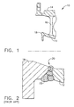
- FIG. 1 schematically represents a compressor rear frame (CRF) 10 of the CF6-50 high-bypass gas turbine engine manufactured by the General Electric Company.
- the frame 10 can be seen as comprising inner and outer casing walls 12 and 14 interconnected by radially-extending struts 16.
- a support flange 18 located at the forward end of the inner casing wall 12 is adapted to carry a stationary seal, referred to as the compressor discharge pressure (CDP) seal (not shown).
- CDP compressor discharge pressure
- the frame 10 is installed in an engine, the CDP seal is positioned in close proximity to a seal disk (not shown) mounted on a shaft that interconnects the high pressure turbine and compressor of the engine.
- the CDP seal and seal teeth on the seal disk cooperate to create a tortuous flowpath between the inner casing wall 12 and the rotating shaft, thereby minimizing the amount of compressor discharge air bypassing the compressor downstream of the seal.
- the support flange 18 inevitably requires replacement as a result of weld repairs performed on the frame 10 that cause distortion, resulting in the movement of the flange 18 to the extent that the dimensional limits of the flange 18 cannot be recovered.
- the inner casing wall 12 is typically machined to remove the flange 18, and a rough-machined annular-shaped flange is welded in its place. In this manner, the outer casing wall 14 and the bulk of the inner casing wall 12 can be salvaged.
- suitable weld processes for welding the replacement flange 18 are dependent on the wall thickness of the inner casing wall 12 and flange 18 at the point where the weld is to be performed.
- Thin walls of up to approximately 0.090 inch (about 2.3 mm) can be welded by gas tungsten arc welding (GTAW) using a single-pass butt joint weld configuration.
- GTAW gas tungsten arc welding
- the inner casing wall 12 of the CF6-50 engine has a nominal wall thickness of about 0.140 inch (about 3.56 mm).
- EB welding would typically be considered in combination with essentially the same single-pass butt joint configuration used with repairs preformed by GTAW.
- EB welding cannot be used to perform this type of weld repair on the CF6-50 frame 10.
- PE-GTAW penetration-enhanced gas tungsten arc welding
- One such process makes use of a weld penetration-enhancing flux disclosed in U.S. Patent No. 6,664,508 to Johnson et al.
- the flux commercially available under the name Ni-139 from the Edison Welding Institute, Inc. (EWI), is disclosed by Johnson et al. as containing titanates and one or more transition metal oxides. It would be desirable if a single-pass GTAW processing utilizing a penetration-enhancing flux of the type disclosed by Johnson et al. could be adapted for use in welding compressor rear frames of gas turbine engines, and particularly the CRF of the CF6-50 engine.
- the present invention provides a weld process suitable for repairing compressor rear frames of gas turbine engines, and more particularly welding a new seal flange to a compressor rear frame in a single pass using GTAW.
- a modified PE-GTAW process including welding equipment, welding parameters and a weld joint configuration adapted for use with the process, the seal flange of a compressor rear frame can be replaced without causing undue distortion of the frame.
- the weld joint configuration is adapted to accommodate out-of-round conditions of the frame.
- the process provides for subsequent "cosmetic" welds to be performed, during which filler wire may be deposited to achieve dimensional and mechanical property requirements for the frame and the repair.
- Compressor rear frames of the type repaired by the process of this invention generally comprise a cylindrically-shaped outer casing wall that substantially circumscribes a cylindrically-shaped inner casing wall on which the flange to be replaced is located.
- the process generally entails removing the flange from the inner casing wall to define an annular face on the inner casing wall, and fabricating a replacement flange to have an annular face with a width that is greater than the width of the annular face of the inner casing wall.
- the annular faces of the replacement flange and the inner casing wall are then mated to define a joint therebetween.
- a single-pass gas tungsten arc welding operation is performed by generating an electric arc between an electrode and the joint between the adjacent surfaces of the replacement flange and the inner casing wall.
- the welding operation is carried out to form a root weldment that extends completely through the joint to metallurgically join the replacement flange to the inner casing wall.
- substantially all of the penetration-enhancing flux that remains following the welding operation is removed, and a second single-pass gas tungsten arc welding operation is performed to smooth the root weldment.
- the second operation may deposit a filler on the root weldment and form a second weldment that does not penetrate through the root weldment.
- the purpose of the second weldment includes bringing the dimensions of the final weld joint within accepted ranges. Using a generally conventional GTAW process for this purpose, machining of the final weldment can be avoided yet suitable mechanical properties, including fatigue strength, can be achieved for the frame.
- the repair process of the present invention avoids the previous requirement for a special joint preparation to achieve full penetration of a GTAW weldment through a thick wall, such as the inner casing wall of a compressor rear frame. Furthermore, only two weld passes are necessary to replace the seal flange of a compressor rear frame, thereby reducing the risk of unacceptable distortion of the frame. Finally, the repair process of this invention makes use of a joint configuration in which the replacement flange is wider than the inner casing wall so as to accommodate out-of-round conditions of the casing wall. In this manner, machining is avoided that might otherwise reduce the wall thickness below the allowable range.
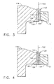
- Figures 3 and 4 show a weld joint 120 formed between a replacement seal flange 118 and the forward end of an inner casing wall of a compressor rear frame (CRF). Similar to Figure 2 , Figures 3 and 4 are represented as details of the compressor rear frame 10 of Figure 1 , and therefore the inner casing wall is identified with reference number 12.
- the compressor rear frame 10 is preferably formed of a nickel-base superalloy, such as Inconel 718, though the invention is also applicable to welding of other components formed of various materials and for which weld penetration and quality are critical for achieving acceptable mechanical properties, including strength and fatigue life.
- the frame 10 comprises a cylindrically-shaped inner casing wall 12 and a cylindrically-shaped outer casing wall 14 that substantially circumscribes the inner casing wall 12.
- the flange 118 of Figures 3 and 4 replaces the compressor discharge pressure (CDP) seal flange 18 of Figure 1 , which can be seen to project radially inward from the forward end of the inner casing wall 12.
- the original and replacement seal flanges 18 and 118 are substantially normal to the longitudinal axis of the inner casing wall 12.
- the original flange 18 has been removed from the inner casing wall 12 by making a cut at a location axially inward from the flange 18, so that the flange 18 and a contiguous portion of the inner casing wall 12 were removed together.
- the replacement flange 118 is fabricated to be similar in shape to the original flange 18, and has an annular face 132 that abuts an annular face 130 of the inner casing wall 12 formed when the original flange 18 was removed.
- the weld joint 120 represented in Figure 3 is shown in a condition following a single weld pass using a welding process in accordance with the present invention.
- the weld joint 120 comprises a root weldment 124 only.
- a "cosmetic" weld pass is subsequently performed to form a second weldment 126 shown in Figure 4 .
- the second weldment 126 completely overlays but does not penetrate through the root weldment 124, as will be discussed in further detail with reference to Figures 5 and 6 .
- the original weld plane 122 defined by mating of the annular faces 130 and 132 of the inner casing wall 12 and replacement flange 118, respectively, is identified in Figures 3 and 4 .
- the annular faces 130 and 132 can be seen as being mated in a configuration commonly known as a square butt joint, in which the weld plane 122 is substantially perpendicular to the adjacent surfaces 134 and 136 of the wall 12 and flange 118 on the side from which the weld operation will be performed. From this it is evident that a special weld preparation, such as the V-shaped channel 22 depicted in Figure 2 , is not required to perform the weld operation of this invention. Instead of the channel 22 of Figure 2 , the faces 130 and 132 are mated to form a continuous, gap-free joint along the entire weld plane 122.
- the inner casing wall 12 of the CF6-50 engine has a nominal thickness of about 0.140 inch (about 3.56 mm) measured in the radial direction of the frame 10 and wall 12. From Figure 3 , it is evident that the face 132 of the replacement flange 118 abutting the face 130 of inner casing wall 12 has a thickness (radial width) significantly greater than that of the face 130.
- the thickness of the replacement flange 118 at the face 132 can be about 0.185 inch (about 4.6 mm), or roughly about 50% thicker than the thickness of the wall 12 adjacent its face 130.
- the greater thickness of the flange face 132 allows for mismatch between the faces 130 and 132 that may occur as a result of the inner casing wall 12 being out-of-round due to service and/or repair-induced distortions.
- the single-pass welding process employed by this invention is able to penetrate the entire thickness of the weld plane 122, producing the root weldment 124 without adverse effects that might result from the markedly different thicknesses of the faces 130 and 132.
- the casing wall 12 and the replacement flange 118 are preferably tack welded together using a manual GTAW technique.
- the tack welding operation may employ a filler material that is deposited intermittently along the circumference of the wall 12 to join the faces 130 and 132 of the wall 12 and flange 118 at their adjacent surfaces 134 and 136.
- a suitable filler material is AMS 5832, which is the Aerospace Materials Specification that covers Inconel 718 as well as several other commercially-available alloys.
- Other suitable filler materials are foreseeable, depending on the materials being joined.
- the tack welds need only be of sufficient size and number to secure the wall 12 and flange 118 together for undergoing the weld operation described below.
- the preferred welding process of this invention is a single-pass penetration-enhanced gas tungsten arc welding (PE-GTAW) process that utilizes a penetration-enhancing flux.
- PE-GTAW penetration-enhanced gas tungsten arc welding
- a preferred flux is disclosed in U.S. Patent No. 6,664,508 to Johnson et al., and commercially available under the name Ni-139 from the Edison Welding Institute, Inc. (EWI). This flux is disclosed as containing titanates and one or more transition metal oxides.
- a uniform coating 128 of the flux is deposited on the surfaces 134 and 136 of the wall 12 and flange 118, which are on the side of the joint from which the welding operation will be performed.
- welding parameters for the PE-GTAW process include the following: Current 210 to 215 Amps (DC, straight polarity) Voltage 9.7-9.9 V Electrode 3/32 inch (0.24 mm) diameter Travel Speed .5 ipm (about 24 cm/minute) Filler Material None Shielding gas Argon Shielding gas flow rate 25 to 35 cfh (0.71 to 0.99 m 3 /h) Torch type HW27
- the torch-to-work distance is preferably maintained with an automatic voltage control (AVC) capable of precisely controlling the distance between the weld electrode and the adjacent surfaces 134 and 136 of the wall 12 and flange 118.
- AVC automatic voltage control
- the welded assembly preferably undergoes a "cosmetic" welding operation in which the surfaces 134 and 136 undergo a second welding pass, the result of which is depicted in Figure 4 .
- this second welding operation does not utilize a penetration-enhancing flux.
- the presence of such a flux during the cosmetic weld operation yields undesirable results, as will be explained below.
- the cosmetic weld operation may employ a filler material that is deposited to form a second weldment 126.
- This second "cosmetic" weldment 126 produces not only a desirable cosmetic appearance to the final weld joint 120, but also improves the surface geometry of the weld joint 120. Smoothing of the weld joint 120 facilitates any subsequent machining of the flange 118 necessary to restore the original flange-wall transition.
- Suitable filler materials will depend on the materials being joined. As with the tack weld discussed above, a suitable filler material is AMS 5832 if the casing wall 12 and replacement flange 118 are formed of Inconel 718.
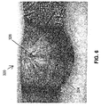
- a scanned image of a weld joint 220 produced using the weld process described above is shown in Figure 5 .
- the weld joint 220 can be seen as comprising a root weldment 224 overlaid by a cosmetic weldment 226.
- the cosmetic weldment 226 completely covers, but does not penetrate through, the root weldment 224. More particularly, the cosmetic weldment 226 can be seen to penetrate less than half the thickness of the weld joint 220.
- the cosmetic weldment 126 preferably penetrates not more than 30% of the thickness of the weld joint 120, such as about 25% of the thickness of the weld joint 120.
- the weld joint 320 of Figure 6 comprises a root weldment 324 and a cosmetic weldment 326.
- the cosmetic weldment 326 does not completely cover the root weldment 324, and penetrates more than half the thickness of the root weldment 324.
- Disadvantages of the weld joint 320 of Figure 6 include difficulty with machining and undercutting of the root weldment 324 at the surface, reducing the tensile and fatigue strength of the weld joint 220.
Claims (10)
- Procédé permettant de réparer un bâti arrière (10) de compresseur sur un moteur à turbine à gaz, le bâti arrière (10) de compresseur comprenant une paroi (12) de carter intérieure de forme cylindrique et une paroi (14) de carter extérieure de forme cylindrique qui recouvre sensiblement la paroi (12) de carter intérieure, ladite paroi (12) de carter intérieure comportant une bride (18) conçue pour supporter un élément d'étanchéité, le procédé consistant à :retirer la bride (18) de la paroi (12) de carter intérieure pour définir une face annulaire (130) sur la paroi (12) de carter intérieure, la face annulaire (130) présentant une certaine largeur ;fabriquer une bride (118) de remplacement pour avoir une face annulaire (132) d'une largeur supérieure à la largeur de la face annulaire (130) de la paroi (12) de carter intérieure ;accoupler les faces annulaires (130, 132) de la bride (118) de remplacement et de la paroi (12) de carter intérieure pour définir un joint (122) entre celles-ci ;déposer un flux (128) améliorant la pénétration sur les surfaces adjacentes (134, 136) de la bride (118) de remplacement et de la paroi (12) de carter intérieure séparées par le joint (122) ;effectuer une opération de soudage à l'arc en atmosphère inerte avec électrode de tungstène (TIG) en une passe en générant un arc électrique entre une électrode et le joint (122) situé entre les surfaces adjacentes (134, 136) de la bride (118) de remplacement et de la paroi (12) de carter intérieure, l'opération de soudage formant un ensemble soudé (124) de fond qui s'étend complètement à travers le joint (122) pour relier de façon métallurgique la bride (118) de remplacement à la paroi (12) de carter intérieure ;retirer pratiquement tout le flux (128) améliorant la pénétration qui reste après l'opération de soudage ; puiseffectuer une opération de soudage TIG pour former un deuxième ensemble soudé (126) qui ne pénètre pas à travers l'ensemble soudé (124) de fond.
- Procédé selon la revendication 1, caractérisé en ce que le joint (122) entre la bride (118) de remplacement et la paroi (12) de carter intérieure est un joint (122) en I de telle sorte qu'il n'y a pas d'espace entre les faces annulaires (130, 132) de la bride (118) de remplacement et de la paroi (12) de carter intérieure après l'étape d'accouplement.
- Procédé selon la revendication 1 ou 2, caractérisé en ce que les faces annulaires (130, 132) de la bride (118) de remplacement et de la paroi (12) de carter intérieure se trouvent dans un plan sensiblement perpendiculaire à un axe longitudinal de la paroi (12) de carter intérieure.
- Procédé selon les revendications 1, 2 ou 3, caractérisé en ce que la largeur de la face annulaire (130) de la paroi (12) de carter intérieure est supérieure à 2,3 mm.
- Procédé selon l'une des revendications précédentes, caractérisé en ce que la largeur de la face annulaire (132) de la bride (118) de remplacement est environ 50 % supérieure à la largeur de la face annulaire (130) de la paroi (12) de carter intérieure.
- Procédé selon l'une des revendications précédentes, caractérisé en ce que le deuxième ensemble soudé (126) couvre complètement l'ensemble soudé (124) de fond.
- Procédé selon l'une des revendications précédentes, caractérisé en ce que le deuxième ensemble soudé (126) ne pénètre pas de plus de 30 % à travers l'épaisseur de l'ensemble soudé (124) de fond.
- Procédé selon l'une des revendications précédentes, caractérisé en ce que, pendant l'étape de réalisation de l'opération de soudage TIG en une passe permettant de former l'ensemble soudé (124) de fond, une régulation automatique de la tension est utilisée pour maintenir une longueur d'arc sensiblement constante entre l'électrode et le joint (122) situé entre les surfaces adjacentes (134, 136) de la bride (118) de remplacement et de la paroi (12) de carter intérieure.
- Procédé selon l'une des revendications précédentes, caractérisé en ce que les surfaces adjacentes (134, 136) de la bride (118) de remplacement et de la paroi (12) de carter intérieure sont situées à l'intérieur de la paroi (12) de carter intérieure.
- Procédé selon l'une des revendications précédentes, caractérisé en ce que le flux (128) contient des titanates et un ou plusieurs oxydes de métaux de transition.
Applications Claiming Priority (2)
| Application Number | Priority Date | Filing Date | Title |
|---|---|---|---|
| US709051 | 1991-06-03 | ||
| US10/709,051 US6969826B2 (en) | 2004-04-08 | 2004-04-08 | Welding process |
Publications (3)
| Publication Number | Publication Date |
|---|---|
| EP1584402A2 EP1584402A2 (fr) | 2005-10-12 |
| EP1584402A3 EP1584402A3 (fr) | 2006-06-21 |
| EP1584402B1 true EP1584402B1 (fr) | 2010-05-26 |
Family
ID=34911160
Family Applications (1)
| Application Number | Title | Priority Date | Filing Date |
|---|---|---|---|
| EP05251980A Expired - Fee Related EP1584402B1 (fr) | 2004-04-08 | 2005-03-30 | Méthode de soudage |
Country Status (5)
| Country | Link |
|---|---|
| US (1) | US6969826B2 (fr) |
| EP (1) | EP1584402B1 (fr) |
| JP (1) | JP4933054B2 (fr) |
| CN (1) | CN100484679C (fr) |
| DE (1) | DE602005021424D1 (fr) |
Families Citing this family (44)
| Publication number | Priority date | Publication date | Assignee | Title |
|---|---|---|---|---|
| EP1512481A3 (fr) * | 2003-09-02 | 2011-09-28 | Illinois Tool Works Inc. | Soudage-GMA à tension regulée utilisant une source de puissance avec courant constant et un dispositif d'avance du fil à gain variable |
| US8079773B2 (en) * | 2005-10-18 | 2011-12-20 | General Electric Company | Methods and apparatus for assembling composite structures |
| US20070241169A1 (en) | 2006-04-13 | 2007-10-18 | General Electric Company | Method for welding nickel-based superalloys |
| EP1946881A1 (fr) * | 2007-01-17 | 2008-07-23 | Siemens Aktiengesellschaft | Matériau d'apport destiné au soudage de superalliages et procédé de soudage avec matériau d'apport |
| WO2008098614A1 (fr) * | 2007-02-13 | 2008-08-21 | Siemens Aktiengesellschaft | Réparation par soudage de défauts en position intérieure |
| US20080216300A1 (en) * | 2007-03-06 | 2008-09-11 | United Technologies Corporation | Splitter fairing repair |
| FR2920681B1 (fr) | 2007-09-10 | 2009-12-04 | Snecma | Utilisation d'un flux activant pour le soudage tig de pieces metalliques |
| US9765622B2 (en) * | 2007-09-12 | 2017-09-19 | United Technologies Corporation | Methods for performing gas turbine engine casing repairs and repaired cases |
| US8578579B2 (en) * | 2007-12-11 | 2013-11-12 | General Electric Company | System and method for adaptive machining |
| US8510926B2 (en) * | 2008-05-05 | 2013-08-20 | United Technologies Corporation | Method for repairing a gas turbine engine component |
| US20090320288A1 (en) * | 2008-06-30 | 2009-12-31 | Caterpillar Inc. | Method for repairing a turbine |
| US20100102048A1 (en) * | 2008-10-24 | 2010-04-29 | General Electric Company | Methods and Apparatus for Welding |
| JP2010131639A (ja) * | 2008-12-05 | 2010-06-17 | Mitsubishi Heavy Ind Ltd | クラッド溶接方法 |
| JP5463527B2 (ja) * | 2008-12-18 | 2014-04-09 | 独立行政法人日本原子力研究開発機構 | オーステナイト系ステンレス鋼からなる溶接材料およびそれを用いた応力腐食割れ予防保全方法ならびに粒界腐食予防保全方法 |
| US8092168B2 (en) * | 2009-04-10 | 2012-01-10 | General Electric Company | Patch plug repair of a compressor case stator ring hook, near the horizontal joint |
| JP5594814B2 (ja) * | 2009-06-12 | 2014-09-24 | 愛知産業株式会社 | 円周曲面へのチューブ溶接方法 |
| US20150275687A1 (en) * | 2011-01-13 | 2015-10-01 | Siemens Energy, Inc. | Localized repair of superalloy component |
| US20120223057A1 (en) * | 2011-03-02 | 2012-09-06 | Lucian Iordache | Gas tungsten arc welding using flux coated electrodes |
| US9903216B2 (en) | 2012-12-29 | 2018-02-27 | United Technologies Corporation | Gas turbine seal assembly and seal support |
| EP2938834A1 (fr) | 2012-12-29 | 2015-11-04 | United Technologies Corporation | Pare-chocs pour joints d'étanchéité dans un carter d'échappement de turbine |
| WO2014105800A1 (fr) | 2012-12-29 | 2014-07-03 | United Technologies Corporation | Ensemble d'étanchéité de turbine à gaz et support d'étanchéité |
| WO2014105619A1 (fr) | 2012-12-29 | 2014-07-03 | United Technologies Corporation | Bossage multifonction pour carter de sortie turbine |
| US9982561B2 (en) | 2012-12-29 | 2018-05-29 | United Technologies Corporation | Heat shield for cooling a strut |
| WO2014105602A1 (fr) | 2012-12-29 | 2014-07-03 | United Technologies Corporation | Bouclier thermique pour carter |
| EP2938845A4 (fr) | 2012-12-29 | 2016-01-13 | United Technologies Corp | Architecture de carter de sortie de turbine |
| WO2014105603A1 (fr) | 2012-12-29 | 2014-07-03 | United Technologies Corporation | Bouclier thermique en plusieurs pièces |
| US10240481B2 (en) | 2012-12-29 | 2019-03-26 | United Technologies Corporation | Angled cut to direct radiative heat load |
| WO2014105657A1 (fr) | 2012-12-29 | 2014-07-03 | United Technologies Corporation | Monture à pattes pouvant être infléchies |
| US10053998B2 (en) | 2012-12-29 | 2018-08-21 | United Technologies Corporation | Multi-purpose gas turbine seal support and assembly |
| WO2014105496A1 (fr) | 2012-12-29 | 2014-07-03 | United Technologies Corporation | Élément et ensemble de déviation de flux |
| WO2014143329A2 (fr) | 2012-12-29 | 2014-09-18 | United Technologies Corporation | Trous de refroidissement pour jonction de châssis |
| GB2524211B (en) | 2012-12-29 | 2021-05-26 | United Technologies Corp | Turbine frame assembly and method of designing turbine frame assembly |
| US9903224B2 (en) | 2012-12-29 | 2018-02-27 | United Technologies Corporation | Scupper channelling in gas turbine modules |
| WO2014105512A1 (fr) | 2012-12-29 | 2014-07-03 | United Technologies Corporation | Liaison mécanique destinée à un écran thermique segmenté |
| US10138742B2 (en) | 2012-12-29 | 2018-11-27 | United Technologies Corporation | Multi-ply finger seal |
| US10060279B2 (en) | 2012-12-29 | 2018-08-28 | United Technologies Corporation | Seal support disk and assembly |
| DE112013006315T5 (de) | 2012-12-31 | 2015-09-17 | United Technologies Corporation | Mehrteiliger Rahmen eines Turbinenabgasgehäuses |
| EP2938860B1 (fr) | 2012-12-31 | 2018-08-29 | United Technologies Corporation | Cadre à multiples pièces de compartiment d'échappement de turbine |
| US10054009B2 (en) | 2012-12-31 | 2018-08-21 | United Technologies Corporation | Turbine exhaust case multi-piece frame |
| US10330011B2 (en) | 2013-03-11 | 2019-06-25 | United Technologies Corporation | Bench aft sub-assembly for turbine exhaust case fairing |
| US10443447B2 (en) | 2016-03-14 | 2019-10-15 | General Electric Company | Doubler attachment system |
| CN107971693B (zh) * | 2017-11-23 | 2019-03-15 | 中国航发沈阳黎明航空发动机有限责任公司 | 一种钛合金进气机匣的机匣壳体裂纹修理方法 |
| CN113431708B (zh) * | 2021-05-31 | 2022-07-05 | 西安航天动力研究所 | 一种带冷却结构的涡轮壳体及加工方法 |
| CN115870702A (zh) * | 2022-12-07 | 2023-03-31 | 中国航发动力股份有限公司 | 一种保证机匣内套流道宽度的加工方法 |
Family Cites Families (13)
| Publication number | Priority date | Publication date | Assignee | Title |
|---|---|---|---|---|
| US5205465A (en) * | 1990-09-19 | 1993-04-27 | United Technologies Corporation | Method for replacing worn airseal lands on engine compressor or turbine disks |
| US5071054A (en) * | 1990-12-18 | 1991-12-10 | General Electric Company | Fabrication of cast articles from high melting temperature superalloy compositions |
| US5400491A (en) * | 1993-07-14 | 1995-03-28 | United Technologies Corporation | Apparatus for repairing a combustion chamber assembly |
| US5686001A (en) * | 1996-01-16 | 1997-11-11 | United Technologies Corporation | Variable polarity arc technology for the repair of coated articles |
| US5804792A (en) * | 1996-04-09 | 1998-09-08 | Edison Welding Institute, Inc. | Gas tungsten arc welding flux |
| AU6058899A (en) * | 1998-09-24 | 2000-04-10 | Edison Welding Institute | Penetration flux |
| US6233822B1 (en) * | 1998-12-22 | 2001-05-22 | General Electric Company | Repair of high pressure turbine shrouds |
| US6345441B1 (en) * | 2000-07-18 | 2002-02-12 | General Electric Company | Method of repairing combustion chamber liners |
| JP3846169B2 (ja) * | 2000-09-14 | 2006-11-15 | 株式会社日立製作所 | ガスタービンの補修方法 |
| JP3915423B2 (ja) * | 2001-03-29 | 2007-05-16 | 株式会社日立製作所 | ガスタービン燃焼器ライナー構造とその補修方法 |
| US6607114B2 (en) * | 2001-10-12 | 2003-08-19 | General Electric Company | Weld fixture and method for repairing annular components |
| JP2003343280A (ja) * | 2002-05-30 | 2003-12-03 | Mitsubishi Heavy Ind Ltd | 高温部品のクーポン補修方法及びクーポンを有する高温部品 |
| US6701616B2 (en) * | 2002-06-28 | 2004-03-09 | General Electric Company | Method of repairing shroud tip overlap on turbine buckets |
-
2004
- 2004-04-08 US US10/709,051 patent/US6969826B2/en not_active Expired - Fee Related
-
2005
- 2005-03-30 DE DE602005021424T patent/DE602005021424D1/de active Active
- 2005-03-30 EP EP05251980A patent/EP1584402B1/fr not_active Expired - Fee Related
- 2005-04-07 JP JP2005110428A patent/JP4933054B2/ja not_active Expired - Fee Related
- 2005-04-08 CN CNB2005100648759A patent/CN100484679C/zh not_active Expired - Fee Related
Also Published As
| Publication number | Publication date |
|---|---|
| DE602005021424D1 (de) | 2010-07-08 |
| US6969826B2 (en) | 2005-11-29 |
| EP1584402A2 (fr) | 2005-10-12 |
| US20050224487A1 (en) | 2005-10-13 |
| JP4933054B2 (ja) | 2012-05-16 |
| JP2005297066A (ja) | 2005-10-27 |
| CN1680066A (zh) | 2005-10-12 |
| EP1584402A3 (fr) | 2006-06-21 |
| CN100484679C (zh) | 2009-05-06 |
Similar Documents
| Publication | Publication Date | Title |
|---|---|---|
| EP1584402B1 (fr) | Méthode de soudage | |
| US8153922B2 (en) | Insert weld repair | |
| US4657171A (en) | Repair of a member having a projection | |
| US7802350B2 (en) | Flange hole repair | |
| US4743165A (en) | Drum rotors for gas turbine engines | |
| EP1688211B1 (fr) | Réparation par soudure à l'arc de plasma d'alliages métaliques à forte teneur en nickel | |
| US6118098A (en) | Turbine rotor modernization and repair method | |
| US8158903B2 (en) | Method for repairing or manufacturing a component | |
| US20060138093A1 (en) | Method and apparatus for repairing superalloy components | |
| EP2298489A1 (fr) | Composition de superalliage et procédé de formation d'un composant de moteur à turbine | |
| WO2010002295A1 (fr) | Procédé de soudage | |
| WO2017074373A1 (fr) | Aube de turbine à gaz en composite métal-céramique | |
| US6996906B2 (en) | Method of repairing a turbine blade and blade repaired thereby | |
| EP1512482B1 (fr) | Méthode pour améliorer la pénétration de soudure par formation d'une couche d'oxyde. | |
| CN110712002A (zh) | 恢复叶片或导叶平台的方法 | |
| US20180304371A1 (en) | Composite metallic and ceramic gas turbine engine blade | |
| JPS63295802A (ja) | 蒸気タ−ビンのノズル板補修方法 | |
| US20230050740A1 (en) | Weld-brazing techniques | |
| KR960004205B1 (ko) | 슈라우드 터어빈 블레이드 |
Legal Events
| Date | Code | Title | Description |
|---|---|---|---|
| PUAI | Public reference made under article 153(3) epc to a published international application that has entered the european phase |
Free format text: ORIGINAL CODE: 0009012 |
|
| AK | Designated contracting states |
Kind code of ref document: A2 Designated state(s): AT BE BG CH CY CZ DE DK EE ES FI FR GB GR HU IE IS IT LI LT LU MC NL PL PT RO SE SI SK TR |
|
| AX | Request for extension of the european patent |
Extension state: AL BA HR LV MK YU |
|
| PUAL | Search report despatched |
Free format text: ORIGINAL CODE: 0009013 |
|
| AK | Designated contracting states |
Kind code of ref document: A3 Designated state(s): AT BE BG CH CY CZ DE DK EE ES FI FR GB GR HU IE IS IT LI LT LU MC NL PL PT RO SE SI SK TR |
|
| AX | Request for extension of the european patent |
Extension state: AL BA HR LV MK YU |
|
| RIC1 | Information provided on ipc code assigned before grant |
Ipc: B23K 9/02 20060101ALI20060512BHEP Ipc: B23P 15/04 20060101ALI20060512BHEP Ipc: B23K 9/235 20060101ALI20060512BHEP Ipc: F01D 5/00 20060101ALI20060512BHEP Ipc: B23K 9/167 20060101AFI20050711BHEP |
|
| 17P | Request for examination filed |
Effective date: 20061221 |
|
| AKX | Designation fees paid |
Designated state(s): DE FR GB IT SE |
|
| GRAP | Despatch of communication of intention to grant a patent |
Free format text: ORIGINAL CODE: EPIDOSNIGR1 |
|
| GRAS | Grant fee paid |
Free format text: ORIGINAL CODE: EPIDOSNIGR3 |
|
| GRAA | (expected) grant |
Free format text: ORIGINAL CODE: 0009210 |
|
| AK | Designated contracting states |
Kind code of ref document: B1 Designated state(s): DE FR GB IT SE |
|
| REG | Reference to a national code |
Ref country code: GB Ref legal event code: FG4D |
|
| REF | Corresponds to: |
Ref document number: 602005021424 Country of ref document: DE Date of ref document: 20100708 Kind code of ref document: P |
|
| REG | Reference to a national code |
Ref country code: SE Ref legal event code: TRGR |
|
| PLBE | No opposition filed within time limit |
Free format text: ORIGINAL CODE: 0009261 |
|
| STAA | Information on the status of an ep patent application or granted ep patent |
Free format text: STATUS: NO OPPOSITION FILED WITHIN TIME LIMIT |
|
| 26N | No opposition filed |
Effective date: 20110301 |
|
| REG | Reference to a national code |
Ref country code: DE Ref legal event code: R097 Ref document number: 602005021424 Country of ref document: DE Effective date: 20110228 |
|
| PGFP | Annual fee paid to national office [announced via postgrant information from national office to epo] |
Ref country code: FR Payment date: 20120406 Year of fee payment: 8 |
|
| PGFP | Annual fee paid to national office [announced via postgrant information from national office to epo] |
Ref country code: SE Payment date: 20120328 Year of fee payment: 8 Ref country code: GB Payment date: 20120326 Year of fee payment: 8 Ref country code: IT Payment date: 20120323 Year of fee payment: 8 |
|
| PGFP | Annual fee paid to national office [announced via postgrant information from national office to epo] |
Ref country code: DE Payment date: 20120328 Year of fee payment: 8 |
|
| REG | Reference to a national code |
Ref country code: SE Ref legal event code: EUG |
|
| PG25 | Lapsed in a contracting state [announced via postgrant information from national office to epo] |
Ref country code: SE Free format text: LAPSE BECAUSE OF NON-PAYMENT OF DUE FEES Effective date: 20130331 |
|
| GBPC | Gb: european patent ceased through non-payment of renewal fee |
Effective date: 20130330 |
|
| REG | Reference to a national code |
Ref country code: FR Ref legal event code: ST Effective date: 20131129 |
|
| REG | Reference to a national code |
Ref country code: DE Ref legal event code: R119 Ref document number: 602005021424 Country of ref document: DE Effective date: 20131001 |
|
| PG25 | Lapsed in a contracting state [announced via postgrant information from national office to epo] |
Ref country code: DE Free format text: LAPSE BECAUSE OF NON-PAYMENT OF DUE FEES Effective date: 20131001 Ref country code: FR Free format text: LAPSE BECAUSE OF NON-PAYMENT OF DUE FEES Effective date: 20130402 Ref country code: GB Free format text: LAPSE BECAUSE OF NON-PAYMENT OF DUE FEES Effective date: 20130330 |
|
| PG25 | Lapsed in a contracting state [announced via postgrant information from national office to epo] |
Ref country code: IT Free format text: LAPSE BECAUSE OF NON-PAYMENT OF DUE FEES Effective date: 20130330 |