EP1584394A2 - Flushing and filtering system for electroerosion machining - Google Patents
Flushing and filtering system for electroerosion machining Download PDFInfo
- Publication number
- EP1584394A2 EP1584394A2 EP05251809A EP05251809A EP1584394A2 EP 1584394 A2 EP1584394 A2 EP 1584394A2 EP 05251809 A EP05251809 A EP 05251809A EP 05251809 A EP05251809 A EP 05251809A EP 1584394 A2 EP1584394 A2 EP 1584394A2
- Authority
- EP
- European Patent Office
- Prior art keywords
- filtering
- flushing
- machining liquid
- return path
- tank
- Prior art date
- Legal status (The legal status is an assumption and is not a legal conclusion. Google has not performed a legal analysis and makes no representation as to the accuracy of the status listed.)
- Granted
Links
- 238000001914 filtration Methods 0.000 title claims abstract description 73
- 238000003754 machining Methods 0.000 title claims abstract description 51
- 238000011010 flushing procedure Methods 0.000 title claims abstract description 25
- 239000007788 liquid Substances 0.000 claims abstract description 39
- 239000012530 fluid Substances 0.000 claims description 29
- 239000007921 spray Substances 0.000 claims description 2
- 238000005507 spraying Methods 0.000 claims description 2
- 238000000034 method Methods 0.000 description 6
- 208000028659 discharge Diseases 0.000 description 4
- 238000010586 diagram Methods 0.000 description 3
- 239000000463 material Substances 0.000 description 3
- 239000002184 metal Substances 0.000 description 3
- 239000003792 electrolyte Substances 0.000 description 2
- 230000001052 transient effect Effects 0.000 description 2
- 239000004020 conductor Substances 0.000 description 1
- 239000000356 contaminant Substances 0.000 description 1
- 230000007812 deficiency Effects 0.000 description 1
- -1 dielectric Substances 0.000 description 1
- 230000008018 melting Effects 0.000 description 1
- 238000002844 melting Methods 0.000 description 1
- 238000010408 sweeping Methods 0.000 description 1
- 238000009834 vaporization Methods 0.000 description 1
- 230000008016 vaporization Effects 0.000 description 1
Images

Classifications
-
- B—PERFORMING OPERATIONS; TRANSPORTING
- B23—MACHINE TOOLS; METAL-WORKING NOT OTHERWISE PROVIDED FOR
- B23H—WORKING OF METAL BY THE ACTION OF A HIGH CONCENTRATION OF ELECTRIC CURRENT ON A WORKPIECE USING AN ELECTRODE WHICH TAKES THE PLACE OF A TOOL; SUCH WORKING COMBINED WITH OTHER FORMS OF WORKING OF METAL
- B23H1/00—Electrical discharge machining, i.e. removing metal with a series of rapidly recurring electrical discharges between an electrode and a workpiece in the presence of a fluid dielectric
- B23H1/10—Supply or regeneration of working media
Definitions
- the present disclosure relates generally to electroerosion machines and, more particularly, to a flushing and filtering system for electroerosion machines.
- Electroerosion machining is a process in which an electrically conductive metal workpiece is shaped by removing material through melting or vaporization by electrical sparks and arcs.
- the spark discharge and transient arcs are produced by applying controlled direct current between the workpiece (typically anodic or positively charged) and the tool or electrode (typically the cathode or negatively charged).
- the end of the electrode and the workpiece are separated by a spark gap from about 0.01 millimeters to about 0.50 millimeters, and are immersed in or flooded by a dielectric fluid or an electrolyte fluid.
- the fluid in the gap is partially ionized under the DC voltage (pulsed or continuous), thus enabling a spark discharge or transient arc to pass between the tool and the workpiece.
- Each spark and/or arc produces enough heat to melt or vaporize a small quantity of the workpiece, thereby leaving a tiny pit or crater in the work surface.
- Electroerosion machining is also non-contact or minimum-contact machining process that can quickly shape any electrically conductive material regardless of the hardness or toughness of the material.
- electroerosion process a substantial amount of material is removed from the metal workpiece.
- Metal chips are deposited at the bottom of a working tank and subsequently rolled by high pressure flushing. Without adequate filtration, these rolled chips can be pumped back into the machining zone and generate secondary discharge or arcing between the electrode and the workpiece, thereby affecting process stability and surface integrity as well as geometry accuracy.
- the system includes a work tank configured to maintain a workpiece therein, a first filtering stage for roughly filtering residue-containing machining liquid exiting from the work tank, and a second filtering stage for finely filtering roughly-filtered machining liquid exiting from the first filtering stage.
- a method for flushing and filtering an electroerosion machine includes passing a residue-containing machining liquid through a first filtering stage for roughly filtering the residue-containing machining liquid.
- the residue-containing liquid exits from a work tank configured to maintain a workpiece therein.
- the roughly-filtered machining liquid exiting from the first filtering stage is passed into a second filtering stage for fine filtering of the roughly-filtered machining liquid.
- Each filtering stage has a separate filtering tank associated therewith, and a pump to transfer the roughly filtered machining fluid to the fine filtering tank from the rough filtering tank.
- the fine filtered stage further features two fluid return paths, including an additional fluid adding pump in addition to a high-pressure pump for fluid return directly to the tool itself.
- a work tank 102 contains workpiece 104 that is to be milled, shaped or otherwise machined by an electroerosion process.
- an electrode 106 is configured in close proximity to the workpiece 104 through a guide bush 108.
- the electrode 106 has a machining liquid 110 continuously circulated at high pressure therethrough and introduced into a gap between the electrode 106 and the workpiece 104 for facilitating the machining operation.
- the machining liquid 110 is also supplied to the guide bush for exterior flushing of contaminants.
- a liquid adding inlet 112 at the lower portion of the work tank 102 receives machining liquid 110 from a separate input path from that supplying the electrode 106 and guide bush 108, as described in greater detail hereinafter.
- Sufficient machining liquid 110 is introduced into the work tank 102 to as to maintain the workpiece 104 and guide bush 108 in a substantially submerged condition during the machining process.
- a liquid adding outlet/nozzle 113 is configured proximate the top of the work tank 102 for receiving machining liquid 110 and spraying or flushing the machining liquid 110 to the machining area from an up-down or side-to-side direction between the workpiece 104 and electrode 106.
- the nozzle may be used to spray the exterior of the guide bush 108 and the workpiece 104.
- the residue-containing machining liquid 110 exits the bottom of the work tank 102 from outlet 114, and is directed to a first (rough) filtering stage, generally designated at 116.
- a first (rough) filtering stage In order to facilitate the sweeping away of metallic chip residue, the bottom of the work tank 102 may be downwardly sloped or inclined toward outlet 114.
- the first filtering stage 116 includes a first (rough) filtering tank 118, rough filtering device 120 and a rough filtering pump 122 for transferring the resulting roughly filtered machining liquid 110 to a second (fine) filtering stage 124.
- the second filtering stage 124 includes a second (fine) filtering tank 126 in which there is included a fine filtering device 128 for receiving the roughly filtered machining liquid 110 from the first filtering stage 116.
- Two separate exit fluid return paths are used to transfer the resulting finely filtered machining liquid back through the tool electrode 106 and into the work tank 102.
- a first fluid return path is a high-pressure fluid path 130 that includes a high-pressure pump 132 and optional pressure sensor 134 for circulating the finely filtered machining liquid 110 through the electrode 106 and to the guide bush 108.
- a second fluid return path 136 includes a liquid adding pump 138 that supplies finely filtered machining liquid 110 through the liquid adding inlet 112 at the lower portion of the work tank 102.
- the liquid adding pump 138 is turned on to add finely filtered machining fluid (e.g., dielectric, electrolyte) into the work tank 102.
- finely filtered machining fluid e.g., dielectric, electrolyte
- the high pressure pump 132 is turned on, and the normal electroerosion machining cycle starts.
- the outlet 114 is opened while the rough filtering pump 122 between the rough and fine filtering tanks is turned on, causing the system 100 to begin the flushing and filtering cycle.
- the resulting metallic chips are swept away from the workpiece 104 and out of the work tank 102 due to the sloped bottom surface of the work tank 102 and continuous addition of machining fluid 110 through at least two different fluid paths. This also helps to ensure each workpiece is machined under the same conditions, as well as to reduce secondary discharge by the chips. Thus, both process stability and part quality is improved.
Landscapes
- Engineering & Computer Science (AREA)
- Mechanical Engineering (AREA)
- Electrical Discharge Machining, Electrochemical Machining, And Combined Machining (AREA)
Abstract
Description
- The present disclosure relates generally to electroerosion machines and, more particularly, to a flushing and filtering system for electroerosion machines.
- Electroerosion machining is a process in which an electrically conductive metal workpiece is shaped by removing material through melting or vaporization by electrical sparks and arcs. The spark discharge and transient arcs are produced by applying controlled direct current between the workpiece (typically anodic or positively charged) and the tool or electrode (typically the cathode or negatively charged). The end of the electrode and the workpiece are separated by a spark gap from about 0.01 millimeters to about 0.50 millimeters, and are immersed in or flooded by a dielectric fluid or an electrolyte fluid. The fluid in the gap is partially ionized under the DC voltage (pulsed or continuous), thus enabling a spark discharge or transient arc to pass between the tool and the workpiece. Each spark and/or arc produces enough heat to melt or vaporize a small quantity of the workpiece, thereby leaving a tiny pit or crater in the work surface.
- Electroerosion machining is also non-contact or minimum-contact machining process that can quickly shape any electrically conductive material regardless of the hardness or toughness of the material. In the electroerosion process, a substantial amount of material is removed from the metal workpiece. Metal chips are deposited at the bottom of a working tank and subsequently rolled by high pressure flushing. Without adequate filtration, these rolled chips can be pumped back into the machining zone and generate secondary discharge or arcing between the electrode and the workpiece, thereby affecting process stability and surface integrity as well as geometry accuracy.
- At present, existing EDM-type filtration and flushing systems that are adopted for electroerosion machines do not have sufficient filtration systems associated therewith.
- The above discussed and other drawbacks and deficiencies of the prior art are overcome or alleviated by a flushing and filtering system for an electroerosion machine. In an exemplary embodiment, the system includes a work tank configured to maintain a workpiece therein, a first filtering stage for roughly filtering residue-containing machining liquid exiting from the work tank, and a second filtering stage for finely filtering roughly-filtered machining liquid exiting from the first filtering stage.
- In another aspect, a method for flushing and filtering an electroerosion machine includes passing a residue-containing machining liquid through a first filtering stage for roughly filtering the residue-containing machining liquid. The residue-containing liquid exits from a work tank configured to maintain a workpiece therein. The roughly-filtered machining liquid exiting from the first filtering stage is passed into a second filtering stage for fine filtering of the roughly-filtered machining liquid.
- Embodiments of the invention will now be described, by way of example, with reference to the accompanying drawings, in which:
- Figure 1 is schematic diagram of a flushing and filtering system suitable for use with electroerosion machines, in accordance with an embodiment of the invention; and
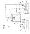
- Figure 2 is schematic diagram of an alternative embodiment of the flushing and filtering system shown in Figure 1.
-
- Disclosed herein is a novel flushing and filtering system for electroerosion machines, in which two separate filtering stages ("rough" and "fine") are implemented. Each filtering stage has a separate filtering tank associated therewith, and a pump to transfer the roughly filtered machining fluid to the fine filtering tank from the rough filtering tank. Moreover, the fine filtered stage further features two fluid return paths, including an additional fluid adding pump in addition to a high-pressure pump for fluid return directly to the tool itself.
- Referring now to Figure 1, there is shown a schematic diagram of a flushing and filtering
system 100 suitable for use for electroerosion machines, in accordance with an embodiment of the invention. As is shown, awork tank 102 containsworkpiece 104 that is to be milled, shaped or otherwise machined by an electroerosion process. To this end, anelectrode 106 is configured in close proximity to theworkpiece 104 through aguide bush 108. As is known in the art, theelectrode 106 has a machiningliquid 110 continuously circulated at high pressure therethrough and introduced into a gap between theelectrode 106 and theworkpiece 104 for facilitating the machining operation. - In addition to being circulated through the electrode center, the
machining liquid 110 is also supplied to the guide bush for exterior flushing of contaminants. Aliquid adding inlet 112 at the lower portion of thework tank 102 receives machiningliquid 110 from a separate input path from that supplying theelectrode 106 andguide bush 108, as described in greater detail hereinafter.Sufficient machining liquid 110 is introduced into thework tank 102 to as to maintain theworkpiece 104 and guidebush 108 in a substantially submerged condition during the machining process. In an alternative embodiment depicted in Figure 2, a liquid adding outlet/nozzle 113 is configured proximate the top of thework tank 102 for receiving machiningliquid 110 and spraying or flushing themachining liquid 110 to the machining area from an up-down or side-to-side direction between theworkpiece 104 andelectrode 106. In other words, in lieu of being submerged in machiningliquid 110, the nozzle may be used to spray the exterior of theguide bush 108 and theworkpiece 104. - In either case, the residue-containing machining
liquid 110 exits the bottom of thework tank 102 fromoutlet 114, and is directed to a first (rough) filtering stage, generally designated at 116. In order to facilitate the sweeping away of metallic chip residue, the bottom of thework tank 102 may be downwardly sloped or inclined towardoutlet 114. Thefirst filtering stage 116 includes a first (rough)filtering tank 118,rough filtering device 120 and arough filtering pump 122 for transferring the resulting roughly filteredmachining liquid 110 to a second (fine)filtering stage 124. - The
second filtering stage 124 includes a second (fine)filtering tank 126 in which there is included afine filtering device 128 for receiving the roughly filteredmachining liquid 110 from thefirst filtering stage 116. Two separate exit fluid return paths are used to transfer the resulting finely filtered machining liquid back through thetool electrode 106 and into thework tank 102. A first fluid return path is a high-pressure fluid path 130 that includes a high-pressure pump 132 andoptional pressure sensor 134 for circulating the finely filteredmachining liquid 110 through theelectrode 106 and to theguide bush 108. A secondfluid return path 136 includes a liquid addingpump 138 that supplies finely filteredmachining liquid 110 through theliquid adding inlet 112 at the lower portion of thework tank 102. - In operation of the flushing and
filtering system 100, theliquid adding pump 138 is turned on to add finely filtered machining fluid (e.g., dielectric, electrolyte) into thework tank 102. When both theworkpiece 104 and theguide bush 108 are submerged into themachining fluid 110, thehigh pressure pump 132 is turned on, and the normal electroerosion machining cycle starts. At the same time, theoutlet 114 is opened while therough filtering pump 122 between the rough and fine filtering tanks is turned on, causing thesystem 100 to begin the flushing and filtering cycle. During machining of theworkpiece 104, the resulting metallic chips are swept away from theworkpiece 104 and out of thework tank 102 due to the sloped bottom surface of thework tank 102 and continuous addition ofmachining fluid 110 through at least two different fluid paths. This also helps to ensure each workpiece is machined under the same conditions, as well as to reduce secondary discharge by the chips. Thus, both process stability and part quality is improved.
Claims (10)
- A flushing and filtering system (100) for an electroerosion machine, comprising:a work tank (102) configured to maintain a workpiece (104) therein;a first filtering stage (116) for roughly filtering residue-containing machining liquid (110) exiting from said work tank (102); anda second filtering stage (124) for finely filtering roughly-filtered machining liquid (110) exiting from said first filtering stage (116).
- The flushing and filtering system (100) of claim 1, further comprising:a first fluid return path (130) to said work tank (102), said first fluid return path (130) comprising a high-pressure return path for introducing finely-filtered machining fluid through an electrode (106) included in the electroerosion machine; anda second fluid return path (136) to said work tank (102), said second fluid return path (136) introducing said finely-filtered machining fluid through a liquid adding inlet (112) disposed at a lower portion of said work tank (102).
- The flushing and filtering system (100) of claim 2, wherein said first filtering stage (116) further comprises:a rough filtering device (120) for receiving residue-containing machining liquid (110) exiting from said work tank (102);a first filtering tank (118) for holding said roughly-filtered machining liquid (110) passed through said rough filtering device (120); anda rough filtering pump (122) for transferring said roughly-filtered machining liquid (110) from said first filtering tank (118) to said second filtering stage (124).
- The flushing and filtering system (100) of claim 3, wherein said second filtering stage (124) further comprises:a fine filtering device (128) for receiving said roughly-filtered machining liquid (110) transferred from said first filtering tank (118);a fine filtering tank (126) for holding said finely-filtered machining liquid (110) passed through said fine filtering device (128);a high-pressure pump (132) for supplying said finely filtered machining liquid (110) through said first fluid return path (130); anda liquid-adding pump (138) for supplying said finely filtered machining liquid (110) through said second fluid return path (136).
- The flushing and filtering system (100) of claim 2, wherein said first fluid return path (130) is further configured so as to provide said finely filtered machining liquid (110) to a guide bush (108), said guide bush (108) having an end of said electrode (106) disposed therethrough.
- The flushing and filtering system (100) of claim 2, wherein a bottom surface of said work tank (102) is sloped so as to cause said residue-containing machining liquid (110) to run toward an outlet (114) proximate the bottom of said work tank (102).
- The flushing and filtering system (100) of claim 4, further comprising a pressure sensor (134) within said first fluid return path.
- The flushing and filtering system (100) of claim 1, wherein said work tank (102) is configured to keep said workpiece (104) completely submerged within said machining fluid.
- The flushing and filtering system (100) of claim 5, wherein work tank (102) is further configured to spray machining fluid on exterior surfaces of said guide bush (108) and said workpiece (104).
- The flushing and filtering system (100) of claim 9, further comprising a nozzle (113) configured for spraying machining fluid on said exterior surfaces of said guide bush (108) and said workpiece (104), said nozzle (113) included within said second fluid return path (136).
Applications Claiming Priority (2)
| Application Number | Priority Date | Filing Date | Title |
|---|---|---|---|
| US10/708,879 US20050218089A1 (en) | 2004-03-30 | 2004-03-30 | Flushing and filtering system for electroerosion machining |
| US708879 | 2004-03-30 |
Publications (3)
| Publication Number | Publication Date |
|---|---|
| EP1584394A2 true EP1584394A2 (en) | 2005-10-12 |
| EP1584394A3 EP1584394A3 (en) | 2005-12-21 |
| EP1584394B1 EP1584394B1 (en) | 2012-08-22 |
Family
ID=34911157
Family Applications (1)
| Application Number | Title | Priority Date | Filing Date |
|---|---|---|---|
| EP05251809A Expired - Lifetime EP1584394B1 (en) | 2004-03-30 | 2005-03-23 | Flushing and filtering system for electroerosion machining |
Country Status (4)
| Country | Link |
|---|---|
| US (1) | US20050218089A1 (en) |
| EP (1) | EP1584394B1 (en) |
| JP (1) | JP5667331B2 (en) |
| CN (1) | CN1676258A (en) |
Cited By (3)
| Publication number | Priority date | Publication date | Assignee | Title |
|---|---|---|---|---|
| CN110732740A (en) * | 2019-10-09 | 2020-01-31 | 郭寒生 | circulation system for machining cutting fluid |
| CN111085740A (en) * | 2019-12-25 | 2020-05-01 | 江西师范高等专科学校 | Metal part precision finishing equipment |
| WO2021013284A3 (en) * | 2019-07-23 | 2021-03-18 | MTU Aero Engines AG | Method and apparatus for machining components by means of electrochemical machining |
Families Citing this family (14)
| Publication number | Priority date | Publication date | Assignee | Title |
|---|---|---|---|---|
| DE102004013031A1 (en) * | 2004-03-16 | 2005-10-06 | Waldrich Siegen Werkzeugmaschinen Gmbh | Method and machine for producing a roll |
| US20050247569A1 (en) * | 2004-05-07 | 2005-11-10 | Lamphere Michael S | Distributed arc electroerosion |
| US7394040B2 (en) * | 2006-03-31 | 2008-07-01 | General Electric Company | Electromachining process and apparatus |
| US7824526B2 (en) | 2006-12-11 | 2010-11-02 | General Electric Company | Adaptive spindle assembly for electroerosion machining on a CNC machine tool |
| JP2010522642A (en) | 2006-12-22 | 2010-07-08 | コーニング インコーポレイテッド | Step-down plunge electric discharge machining |
| US9333577B2 (en) * | 2008-08-29 | 2016-05-10 | General Electric Company | Electro discharge machining apparatus and method |
| US8560110B2 (en) | 2009-06-19 | 2013-10-15 | General Electric Company | Electroerosion control system and a dual mode control system |
| GB201020401D0 (en) * | 2010-12-02 | 2011-01-19 | Rolls Royce Plc | Electrical discharge machining |
| CN103831489B (en) * | 2014-03-18 | 2015-12-16 | 苏州科技学院 | Improve the device and method of numerical control small-hole machined efficiency |
| US10682715B2 (en) | 2015-05-28 | 2020-06-16 | General Electric Company | Method for material recovery in electroerosion machining |
| US11161190B2 (en) | 2015-05-28 | 2021-11-02 | General Electric Company | Electrode for electroerosion machining system |
| CN105345180A (en) * | 2015-11-11 | 2016-02-24 | 安徽天思朴超精密模具股份有限公司 | Wire cutter cleaning device |
| CN107695467B (en) * | 2017-11-20 | 2023-06-27 | 浙江工业大学 | A preparation method and device for a micro-array electrode of pressure-type circulating jet electrolytic machining |
| CN113275677B (en) * | 2021-05-31 | 2022-07-12 | 荆州市紫荆龙创机械制造有限公司 | Working liquid scrap removing device of electric spark forming machine |
Citations (1)
| Publication number | Priority date | Publication date | Assignee | Title |
|---|---|---|---|---|
| US5221467A (en) | 1990-05-30 | 1993-06-22 | Mitsubishi Denki K.K. | Contaminated solution filtration apparatus and machining solution filtration apparatus for machining device |
Family Cites Families (69)
| Publication number | Priority date | Publication date | Assignee | Title |
|---|---|---|---|---|
| US3058895A (en) * | 1958-11-10 | 1962-10-16 | Anocut Eng Co | Electrolytic shaping |
| US3067358A (en) * | 1960-11-02 | 1962-12-04 | Ibm | Electro-erosion apparatus |
| US3469057A (en) * | 1965-02-15 | 1969-09-23 | Owens Corning Fiberglass Corp | Filter system for particulate matter |
| US3435175A (en) * | 1965-09-16 | 1969-03-25 | Elox Inc | Coolant circulation system for electrical discharge machining apparatus |
| US3390247A (en) * | 1966-06-27 | 1968-06-25 | Elox Inc | Coolant circulation system for electrical discharge machining apparatus |
| US3678240A (en) * | 1971-02-24 | 1972-07-18 | Gerald P Dietrick | Fluid handling system for electrical discharge machining equipment |
| GB2009242B (en) * | 1977-11-28 | 1982-05-06 | Inoue Japax Res | Electroerosion machining |
| JPS603934B2 (en) * | 1981-03-17 | 1985-01-31 | 株式会社ソデイツク | Electrical discharge machining method and equipment |
| DE3377864D1 (en) * | 1982-06-23 | 1988-10-06 | Inoue Japax Res | Electrical machining system and method of processing a machining liquid therein |
| JPS6125724A (en) * | 1984-07-10 | 1986-02-04 | Inoue Japax Res Inc | Processing liquid controller for electric discharge processing equipment |
| JPS6133820A (en) * | 1984-07-26 | 1986-02-17 | Inoue Japax Res Inc | Machining liquid circulation supply unit for electric discharge machining |
| US4740315A (en) * | 1984-09-04 | 1988-04-26 | Sune Backman | Filter system for wire electronic discharge machining |
| JPS61241022A (en) * | 1985-04-18 | 1986-10-27 | Inoue Japax Res Inc | Electric discharge machining method |
| JPS6352928A (en) * | 1986-08-20 | 1988-03-07 | Toshiba Ceramics Co Ltd | Electro-discharge processing device |
| JPS6368319A (en) * | 1986-09-06 | 1988-03-28 | Fanuc Ltd | Machining liquid control mechanism for wire-cut electric discharge machining device |
| SE458827B (en) * | 1986-12-15 | 1989-05-16 | Persson Per Oskar Ingf Ab | VAETSKEFILTER |
| EP0303240B1 (en) * | 1987-08-13 | 1994-03-23 | Charmilles Technologies S.A. | Installation and method to filter a machining fluid in an uninterrupted supplying circuit |
| DE3743622A1 (en) * | 1987-12-22 | 1989-07-13 | Agie Ag Ind Elektronik | DEVICE FOR FILTERING THE MACHINE LIQUID OF AN ELECTRIC EDM MACHINE |
| JPH01183317A (en) * | 1988-01-18 | 1989-07-21 | Amada Co Ltd | Working fluid filter for electric discharge machine |
| JPH0241819A (en) * | 1988-08-02 | 1990-02-13 | Shizuoka Seiki Co Ltd | Electrolytic solution treatment tank for electrochemical machine |
| DE3828238A1 (en) * | 1988-08-19 | 1990-02-22 | Agie Ag Ind Elektronik | DEVICE FOR PROCESSING THE MACHINING LIQUID OF AN ELECTROEROSION MACHINE |
| DE3828237C1 (en) * | 1988-08-19 | 1990-01-04 | Ag Fuer Industrielle Elektronik Agie Losone Bei Locarno, Losone, Ch | |
| DE3828236C1 (en) * | 1988-08-19 | 1990-01-04 | Ag Fuer Industrielle Elektronik Agie Losone Bei Locarno, Losone, Ch | |
| US4927547A (en) * | 1988-10-26 | 1990-05-22 | Sune Backman | Method of filtering the effluent from a wire EDM process |
| ES2013662A6 (en) * | 1989-02-21 | 1990-05-16 | Filter system for liquids with particles in suspension | |
| US5177335A (en) * | 1990-01-16 | 1993-01-05 | Westhoff Machine Company | Prefilter for EDM machine |
| US5045161A (en) * | 1990-01-17 | 1991-09-03 | National Research Council | Method and apparatus for electrolytically assisting the mechanical shaping of a workpiece |
| US5189276A (en) * | 1990-02-13 | 1993-02-23 | Mitsubishi Denki K.K. | Method and apparatus for treating the dielectric used in electrical discharge machining |
| EP0519028B1 (en) * | 1991-01-07 | 1999-10-20 | SAE Immobilien AG | Device for cleansing the machining fluid for a spark-erosion or electrochemical processing machine |
| US5217605A (en) * | 1991-09-20 | 1993-06-08 | Kottke Gordon V | Portable multi-element electric discharge machine filter system |
| US5685971A (en) * | 1991-09-30 | 1997-11-11 | General Electric Company | Apparatus and method for forming a variable diameter hole in a conductive workpiece |
| JP3241780B2 (en) * | 1991-12-17 | 2001-12-25 | 株式会社ソディック | Pore electric discharge machine |
| US5464959A (en) * | 1992-04-28 | 1995-11-07 | Sodick Co., Ltd. | Ion exchange treatment method in producing and recycling aqueous EDM fluid |
| JPH0627018U (en) * | 1992-09-09 | 1994-04-12 | 株式会社ソディック | Machining fluid treatment device for electric discharge machine |
| US5434381A (en) * | 1993-09-13 | 1995-07-18 | T-Star Industrial Electronics, Inc. | Apparatus for filtering machining liquid of an electrical discharge machine |
| JP3078441B2 (en) * | 1993-12-24 | 2000-08-21 | 株式会社ソディック | Electric discharge machine |
| US5416289A (en) * | 1994-02-14 | 1995-05-16 | Tanaka; Dwight | Method of and apparatus for increasing the productivity of an electroerosion drill |
| JP3370211B2 (en) * | 1995-07-14 | 2003-01-27 | ファナック株式会社 | Machining fluid treatment equipment for electric discharge machines |
| DE19534277B4 (en) * | 1995-09-15 | 2006-02-09 | Fritz-Herbert Frembgen | Method and apparatus for purifying the electrolyte of an electrochemical machining process |
| JP3540464B2 (en) * | 1995-10-13 | 2004-07-07 | 三菱電機株式会社 | Machining fluid treatment equipment for electric discharge machining equipment |
| JPH1043954A (en) * | 1996-05-27 | 1998-02-17 | Okuma Mach Works Ltd | Accumulated sludge removing device of electric discharge machine |
| US5906737A (en) * | 1997-05-01 | 1999-05-25 | Hoeppner; Michael A. | Filter core system |
| US6183653B1 (en) * | 1998-05-07 | 2001-02-06 | Takeshi Yoshida | Apparatus and method for removing sludge from filter for use in electric discharge machine |
| US5993663A (en) * | 1998-07-09 | 1999-11-30 | Ona Electro-Erosion, S.A. | Liquid filtering system in machine tools |
| US6267868B1 (en) * | 1999-08-16 | 2001-07-31 | General Electric Company | Method and tool for electrochemical machining |
| US6387242B1 (en) * | 1999-08-16 | 2002-05-14 | General Electric Company | Method and tool for electrochemical machining |
| US6234752B1 (en) * | 1999-08-16 | 2001-05-22 | General Electric Company | Method and tool for electrochemical machining |
| DE60041461D1 (en) * | 1999-11-17 | 2009-03-12 | Sodick Co Ltd | LIQUID PROCESSING DEVICE FOR ELECTROCHEMICAL ABLATION |
| JP4430199B2 (en) * | 2000-04-06 | 2010-03-10 | 株式会社エレニックス | Fine hole electric discharge machining method and fine hole electric discharge machining apparatus |
| US6427848B1 (en) * | 2000-06-16 | 2002-08-06 | Chiao-Chin Shih | Dual fabrication liquid circulatory system for an electric discharge fabrication machine |
| US6489582B1 (en) * | 2000-10-10 | 2002-12-03 | General Electric Company | Non-submersion electrodischarge machining using conditioned water as a medium |
| US6416283B1 (en) * | 2000-10-16 | 2002-07-09 | General Electric Company | Electrochemical machining process, electrode therefor and turbine bucket with turbulated cooling passage |
| DE60018086T2 (en) * | 2000-12-22 | 2006-02-23 | Charmilles Technologies S.A. | Apparatus for cleaning processing fluids in an EDM machine |
| JP3572027B2 (en) * | 2001-03-22 | 2004-09-29 | ファナック株式会社 | Machining fluid treatment equipment for wire electric discharge machine |
| US6968290B2 (en) * | 2001-03-27 | 2005-11-22 | General Electric Company | Electrochemical machining tool assembly and method of monitoring electrochemical machining |
| US6806435B2 (en) * | 2001-04-12 | 2004-10-19 | Elenix, Inc. | Small hole electric discharge machine drill provided with depth-specific processing means |
| US6562227B2 (en) * | 2001-07-31 | 2003-05-13 | General Electric Company | Plunge electromachining |
| US6881330B2 (en) * | 2002-03-19 | 2005-04-19 | Hoff Engineering Co., Inc. | Multi-stage EDM filter |
| US6680454B1 (en) * | 2002-12-27 | 2004-01-20 | General Electric Company | Electromachining with perforated electrodes |
| JP2004358573A (en) * | 2003-06-02 | 2004-12-24 | Fanuc Ltd | Machining fluid treating apparatus for wire cut electric discharge machine |
| JP4721898B2 (en) * | 2003-06-04 | 2011-07-13 | 株式会社牧野フライス製作所 | Electric discharge machine and machining method thereof |
| JP4490655B2 (en) * | 2003-06-17 | 2010-06-30 | 株式会社エレニックス | Thin hole electric discharge machining apparatus, die-sculpting / thin hole combined electric discharge machining apparatus and die-cutting / thin hole combined electric discharge machining method using the same apparatus |
| JP3779289B2 (en) * | 2003-07-31 | 2006-05-24 | ファナック株式会社 | Processing fluid processing equipment for electrical discharge machining |
| CA2445077C (en) * | 2003-10-09 | 2008-02-12 | Elenix, Inc. | Small hole electrical discharge machining method and small hole electrical discharge machining apparatus and electrode inserting method and electrode inserting apparatus |
| US6897400B1 (en) * | 2004-03-16 | 2005-05-24 | General Electric Company | Out flushing guide bushing |
| US20050247569A1 (en) * | 2004-05-07 | 2005-11-10 | Lamphere Michael S | Distributed arc electroerosion |
| US8323473B2 (en) * | 2004-11-23 | 2012-12-04 | General Electric Company | Methods and systems for monitoring and controlling electroerosion |
| US7214901B1 (en) * | 2006-01-17 | 2007-05-08 | General Electric Company | Duplex electrical discharge machining |
| JP2007203408A (en) * | 2006-02-01 | 2007-08-16 | Fanuc Ltd | Apparatus for treating working fluid of wire electric discharge machine |
-
2004
- 2004-03-30 US US10/708,879 patent/US20050218089A1/en not_active Abandoned
-
2005
- 2005-03-23 EP EP05251809A patent/EP1584394B1/en not_active Expired - Lifetime
- 2005-03-29 JP JP2005093543A patent/JP5667331B2/en not_active Expired - Lifetime
- 2005-03-30 CN CNA2005100627112A patent/CN1676258A/en active Pending
Patent Citations (1)
| Publication number | Priority date | Publication date | Assignee | Title |
|---|---|---|---|---|
| US5221467A (en) | 1990-05-30 | 1993-06-22 | Mitsubishi Denki K.K. | Contaminated solution filtration apparatus and machining solution filtration apparatus for machining device |
Cited By (5)
| Publication number | Priority date | Publication date | Assignee | Title |
|---|---|---|---|---|
| WO2021013284A3 (en) * | 2019-07-23 | 2021-03-18 | MTU Aero Engines AG | Method and apparatus for machining components by means of electrochemical machining |
| US12240050B2 (en) | 2019-07-23 | 2025-03-04 | MTU Aero Engines AG | Method and apparatus for machining components by means of electrochemical machining |
| CN110732740A (en) * | 2019-10-09 | 2020-01-31 | 郭寒生 | circulation system for machining cutting fluid |
| CN111085740A (en) * | 2019-12-25 | 2020-05-01 | 江西师范高等专科学校 | Metal part precision finishing equipment |
| CN111085740B (en) * | 2019-12-25 | 2020-12-01 | 江西师范高等专科学校 | A kind of metal parts precision machining equipment |
Also Published As
| Publication number | Publication date |
|---|---|
| US20050218089A1 (en) | 2005-10-06 |
| JP5667331B2 (en) | 2015-02-12 |
| EP1584394A3 (en) | 2005-12-21 |
| CN1676258A (en) | 2005-10-05 |
| EP1584394B1 (en) | 2012-08-22 |
| JP2005279924A (en) | 2005-10-13 |
Similar Documents
| Publication | Publication Date | Title |
|---|---|---|
| EP1584394B1 (en) | Flushing and filtering system for electroerosion machining | |
| JP4774177B2 (en) | Improved method and apparatus for cleaning and / or coating metal surfaces using electroplasma technology | |
| Yan et al. | Surface quality improvement of wire-EDM using a fine-finish power supply | |
| US10022812B2 (en) | Methods for the electroerosion machining of high-performance metal alloys | |
| Bojorquez et al. | Formation of a crater in the workpiece on an electrical discharge machine | |
| Fuller | Electrical discharge machining | |
| US20070228017A1 (en) | Electromachining process and apparatus | |
| JP2013132735A (en) | Wire electric discharge machine dissolving inert gas in machining fluid and wire electric discharge machining method | |
| CN102046318B (en) | Electric discharge machining apparatus and electric discharge machining method | |
| US10556280B2 (en) | Methods and systems for electrochemical machining | |
| Xiaowei et al. | A combined electrical machining process for the production of a flexure hinge | |
| CN118404153A (en) | Modular electrolytic electrolytic milling tool and method | |
| JP2768194B2 (en) | Wire electric discharge machine | |
| US9254530B2 (en) | Method for removing material from a component, and electrode | |
| JP2002292524A (en) | Electrolytic finishing of EDM surface | |
| CN101801579B (en) | Device and method for electrochemical treatment | |
| TWI910056B (en) | Method for electro chemical machining | |
| JP3058308B2 (en) | Wire cut electric discharge machining method | |
| JP2001062632A (en) | Metal working method and equipment | |
| Allison | The case for additive technology in EDM | |
| CN120587568A (en) | A powder-mixed electrospark machining device and a metal surface microstructure machining method | |
| Arantes et al. | EDM process aided by erosive wear | |
| Schulze et al. | Process energy sources for the electrochemical machining process and hybrid machining with ECM | |
| Rajurkar et al. | Nonabrasive finishing methods | |
| JP2000015521A (en) | Wire discharge processing method and device |
Legal Events
| Date | Code | Title | Description |
|---|---|---|---|
| PUAI | Public reference made under article 153(3) epc to a published international application that has entered the european phase |
Free format text: ORIGINAL CODE: 0009012 |
|
| AK | Designated contracting states |
Kind code of ref document: A2 Designated state(s): AT BE BG CH CY CZ DE DK EE ES FI FR GB GR HU IE IS IT LI LT LU MC NL PL PT RO SE SI SK TR |
|
| AX | Request for extension of the european patent |
Extension state: AL BA HR LV MK YU |
|
| PUAL | Search report despatched |
Free format text: ORIGINAL CODE: 0009013 |
|
| AK | Designated contracting states |
Kind code of ref document: A3 Designated state(s): AT BE BG CH CY CZ DE DK EE ES FI FR GB GR HU IE IS IT LI LT LU MC NL PL PT RO SE SI SK TR |
|
| AX | Request for extension of the european patent |
Extension state: AL BA HR LV MK YU |
|
| 17P | Request for examination filed |
Effective date: 20060621 |
|
| AKX | Designation fees paid |
Designated state(s): DE FR GB |
|
| 17Q | First examination report despatched |
Effective date: 20080807 |
|
| GRAP | Despatch of communication of intention to grant a patent |
Free format text: ORIGINAL CODE: EPIDOSNIGR1 |
|
| GRAS | Grant fee paid |
Free format text: ORIGINAL CODE: EPIDOSNIGR3 |
|
| GRAA | (expected) grant |
Free format text: ORIGINAL CODE: 0009210 |
|
| AK | Designated contracting states |
Kind code of ref document: B1 Designated state(s): DE FR GB |
|
| REG | Reference to a national code |
Ref country code: GB Ref legal event code: FG4D |
|
| REG | Reference to a national code |
Ref country code: DE Ref legal event code: R096 Ref document number: 602005035737 Country of ref document: DE Effective date: 20121018 |
|
| PLBE | No opposition filed within time limit |
Free format text: ORIGINAL CODE: 0009261 |
|
| STAA | Information on the status of an ep patent application or granted ep patent |
Free format text: STATUS: NO OPPOSITION FILED WITHIN TIME LIMIT |
|
| 26N | No opposition filed |
Effective date: 20130523 |
|
| REG | Reference to a national code |
Ref country code: DE Ref legal event code: R097 Ref document number: 602005035737 Country of ref document: DE Effective date: 20130523 |
|
| REG | Reference to a national code |
Ref country code: FR Ref legal event code: PLFP Year of fee payment: 12 |
|
| REG | Reference to a national code |
Ref country code: FR Ref legal event code: PLFP Year of fee payment: 13 |
|
| REG | Reference to a national code |
Ref country code: FR Ref legal event code: PLFP Year of fee payment: 14 |
|
| PGFP | Annual fee paid to national office [announced via postgrant information from national office to epo] |
Ref country code: FR Payment date: 20200220 Year of fee payment: 16 |
|
| PG25 | Lapsed in a contracting state [announced via postgrant information from national office to epo] |
Ref country code: FR Free format text: LAPSE BECAUSE OF NON-PAYMENT OF DUE FEES Effective date: 20210331 |
|
| PGFP | Annual fee paid to national office [announced via postgrant information from national office to epo] |
Ref country code: DE Payment date: 20240220 Year of fee payment: 20 Ref country code: GB Payment date: 20240220 Year of fee payment: 20 |
|
| REG | Reference to a national code |
Ref country code: DE Ref legal event code: R071 Ref document number: 602005035737 Country of ref document: DE |
|
| REG | Reference to a national code |
Ref country code: GB Ref legal event code: PE20 Expiry date: 20250322 |
|
| PG25 | Lapsed in a contracting state [announced via postgrant information from national office to epo] |
Ref country code: GB Free format text: LAPSE BECAUSE OF EXPIRATION OF PROTECTION Effective date: 20250322 |