The present invention relates to a kit for injecting thermally-conditioned
fluids, particularly for first-aid actions.
The present invention is used particularly but not exclusively in first
aid to individuals affected by a sudden illness or accidents or injuries
directly at the site of the illness, accident or injury, or during their transport
toward an equipped health-care facility, such as for example a surgery or a
hospital.
Merely by way of example, the present invention is used in first aid
provided for work injuries, injuries occurring in locations that are difficult
to reach, such as for example the mountains, for road accidents, natural
calamities or for terrorist attacks.
It is known that individuals struck by a sudden illness or accident or
injury are often in a state of shock characterized by hypovolemia (blood
volume reduction) and hypothermia, and require the infusion of fluids at a
temperature comprised between 33° and 40° C.
In case of brain-affecting events, it is instead appropriate to reduce
the body temperature by infusing chilled fluids.
One of the first treatments that must be provided to patients suffering
from hypothermia and/or hypovolemia, therefore, consists in injecting into
them fluids, such as for example physiological solutions, plasma substitutes
or the like, at a flow-rate and a temperature that allow them to restore
normovolemia and normothermia.
The temperature and the quantity of the injected fluid and the time,
i.e., the injection rate, are decisive factors on which the rescue of these
patients depends; for example, if the temperature of the injected fluid is
lower than the normal average body temperature and/or is injected rapidly,
the condition of the patient worsens instead of improving.
The fluids to be injected are currently packaged in containers, such as
flexible pouches or bottles, which have a dispensing outlet with which the
input end of a withdrawal and conveyance duct is associated, the output end
of said duct being associated with an element (catheter or needle) for
injection into the patient.
To facilitate the discharge of the fluid from the container to the
patient, it is known to arrange and keep the container of fluid at a higher
level than the patient; the consequent increase in potential energy is
converted, for an equal cross-section of the withdrawal and conveyance duct
and minus any losses, into an increase in the discharge rate of the fluid.
In first aid provided directly on-site, generally a health worker
manually supports the container of fluid, keeping it at a higher level than the
patient, whereas in first aid provided during the transport of the patient to an
equipped health-care facility the container is hung from the walls or ceiling
of the transport vehicle (ambulance, helicopter, et cetera).
However, this method has some drawbacks, including the fact that if a
health worker is supporting the container, this limits his maneuvering
ability, since at least one hand is busy, preventing him from performing any
other first-aid procedures that may be necessary; this drawback is even more
onerous if the container is constituted by a pouch, because in this case, in
order to increase the discharge of the fluid the operator in fact also squeezes
said pouch manually, using both hands and being unable to perform any
other maneuver.
Another drawback of this method is that the difference in level
between the container and the patient is often insufficient to impart to the
fluid a chosen flow-rate and therefore a chosen injection rate.
Another drawback of this method is that the containers, and therefore
the fluids contained therein, as well as the duct for withdrawing and
conveying the fluid from the container to the patient, known as infusion set
in the jargon, by being exposed to the environmental conditions of the site
where first aid is performed, may reach an average temperature that is lower
than the normal body temperature, causing or increasing hypothermia of the
patient.
In order to obviate the drawbacks noted above, various devices for
heating the containers and infusion sets of the fluids to be injected and
devices, termed "infusion pressor" in the field, are known which are suitable
to accelerate the flow of the fluid from the container, constituted by a
flexible pouch, to the patient.
In particular, devices for heating the containers of fluid are known
which are substantially constituted by boxes that are thermally insulated
with respect to the environment that surrounds them and inside which the
containers to be conditioned are arranged; said containers are provided with
means for generating heat, based for example on electric resistors or
microwave radiation, and are provided with electronic circuits for
controlling and regulating the temperature.
Devices for heating the duct for withdrawing and conveying the fluid
from the container to the patient are also known which substantially consist
of a metallic element that is coupled to electric resistors supplied with
current and is arranged proximate to the portion of duct to be conditioned;
in this case also, an electronic circuit controls and regulates the temperature
that is reached.
However, these known heating devices are not free from drawbacks,
including the fact that their weight and dimensions are not negligible and
make them particularly difficult and onerous to carry onto rescue sites, that
they are structurally and constructively complicated, they require the
intervention of specialized workers, and have substantial costs.
Another drawback of these known heating devices is that by using
electric power they can cause interference with other electrical/electronic
devices that are present for example on the vehicles that transport aided
individuals.
Devices for heating fluid containers of the so-called chemical type, in
that they utilize the heat produced by an exothermic chemical reaction
between two or more reacting substances, are also known.
These chemical heating devices are substantially constituted by an
enclosure, such as a pouch, which is divided into at least two compartments,
which are mutually separated by a tearable membrane, one of said
compartments containing a first component, the other compartment
containing a second component, said components being suitable to react
with each other with an exothermic reaction.
The reaction is usually a reaction of solution of the first component
(solute) in the second component (solvent).
The first component is generally in the form of solid particles,
granules or the like, and is constituted for example by calcium chloride or
the like; the second component is generally in the form of a liquid and is
constituted for example by water or the like.
At the time of use, an operator acts manually on the enclosure, for
example with a compression or squeezing action, applying thereto a
pressure that breaks the tearable membrane and thus allows the second
component (solvent) to pour from the second compartment into the first
compartment, where it reacts with the first component (solute), dissolving it;
if the reaction is exothermic, heat is generated.
After activating the reaction, the enclosure is placed manually in
contact with the container of the fluid to be administered in order to
condition it thermally and in particular to heat it to the intended
temperature.
These known chemical heating devices, too, are not free from
drawbacks, including the fact that the reaction between the components
contained therein can be activated unintentionally and at inappropriate times
by compressions, impacts or accidental squeezing to which they may be
subjected during storage, movement and handling, which accordingly
require particular care and attention.
These chemical heating devices therefore can exhaust prematurely
their ability to generate heat, losing their function and becoming unusable
when they are actually needed.
Another drawback of chemical devices is that they contain air, which
by having a low heat conductivity acts as an insulator and reduces the
exchange of heat with the environment outside them and in particular with
the containers of the fluids to be conditioned.
Moreover, the presence of air causes another drawback: it in fact
prevents the second component, the one in the liquid state, from diffusing
and distributing throughout the entire volume of the first compartment that
contains the first component, the one in solid particle or granular form; this
reduces the reaction surface, and the reaction remains incomplete, with a
consequent decrease in the efficiency of the device.
Known infusion pressors are substantially constituted by a sort of
centrally-folding case, inside which a pouch of fluid to be injected is fixed,
optionally together with a heating pouch that is one of the chemical heating
devices described above; an air-filled chamber is formed within the walls of
the case and is connected to manual pumping systems.
The pressure applied by the air pumped into the chamber applies to
the pouch of fluid a compression that facilitates the discharge of the fluid
contained therein.
However, these known infusion pressors have drawbacks, including
the fact that since the folding case is open at least along two opposite sides
they do not allow to provide thermal insulation of the pouch of fluid and
optionally of the heating pouch with respect to the environment that
surrounds them, accordingly exposing them to unpredictable temperature
variations, and do not allow to contain any leakage of fluid or heating
solution, which might occur if the respective pouches break; these leaks are
therefore dispersed into the outside environment and can for example
damage other devices or instruments, such as for example the ones that are
present in the cabins of rescue vehicles.
Another drawback of known infusion pressors is that they do not
allow to check the temperature of the fluid that is gradually injected, with
the risk, if said temperature is lower than the normal body temperature, of
causing or worsening the hypothermia of the patient.
Another drawback of known infusion pressors is that their transport,
handling and support are very difficult and require the use of one or both
hands of a health worker, whose possibility to perform other aid maneuvers
is therefore impaired if not eliminated.
The aim of the present invention is to eliminate the drawbacks noted
above, by providing a kit for injecting thermally-conditioned fluids,
particularly for first-aid actions, which allows to inject a fluid in a quantity,
at a rate and at a temperature that can be controlled, assisting the return to
normovolemia and normothermia of patients.
Another obj ect of the present invention is to provide a kit that allows
to improve the heating of the containers of fluid with chemical devices,
increasing their efficiency and their heat exchange capacity, facilitating the
distribution and diffusion of the reacting components within each other and
increasing their reaction surface.
Another obj ect of the present invention is to provide a kit that allows
to improve the functionality and safety of chemical heating devices,
allowing them to be activated only intentionally, without requiring
particular precautions for their storage, movement and handling.
Another object of the present invention is to provide a kit that is
structurally and constructively simple, is compact and lightweight, and is
easy to transport, handle and use even for less expert operators, giving them
ample freedom of maneuver for performing aid procedures.
Within this aim, another obj ect of the present invention is to provide a
structure that is simple, relatively easy to provide in practice, safe in use,
effective in operation, and has a relatively low cost.
This aim and these and other objects that will become better apparent
hereinafter are achieved by the present kit for injecting thermally-conditioned
fluids, particularly for first-aid actions, characterized in that it
comprises a bag in which there is at least one first pocket for containing at
least one pouch of fluid to be injected or at least one pouch of fluid to be
injected and a pouch-shaped thermal reactor, said pocket being provided
with a closure flap that is suitable to contain any leakage of said fluid and/or
reagents of said reactor, and at least one second pocket for containing an
air-filled chamber associated with air pumping means, at least said first
pocket and said flap being made of impermeable and thermally-insulating
material.
Further characteristics and advantages of the present invention will
become better apparent from the following detailed description of a
preferred but not exclusive embodiment of a kit for injecting thermally-conditioned
fluids, particularly for first-aid actions, illustrated by way of
non-limiting example in the accompanying drawings, wherein:
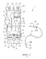
With reference to the figures, the reference numeral 1 generally
designates a kit for injecting thermally-conditioned fluids, particularly for
first-aid actions.
The kit 1 comprises a bag 2, provided with a first pocket 3 and a
second pocket 4, which substantially mutually overlap.
The first pocket 3 is suitable to contain a pouch 5 of fluid to be
injected and optionally also a thermal reactor 6, which is also shaped like a
pouch; said first pocket is also provided with a closure flap 7, which is
suitable to contain leaks of the fluid contained in the pouch 5 and/or of the
reagents of the thermal reactor 6.
The second pocket 4 is suitable to contain an air-filled chamber 8,
which is associated with air pumping means 9.
The first pocket 3 and the flap 7 are made of waterproof and
thermally-insulating material, constituted by the overlap of a waterproof
layer 10 and of one or more thermally-insulating layers 11 made of Nylon
(registered trademark), neoprene or the like.
The outer wall 3a of the first pocket 3, directed away from the second
pocket 4, is reinforced with a layer of inextensible material 12.
At the flap 7, at the outer wall 3a and inner wall 3b of the first pocket
3 onto which it is folded, and at the end portions 13 of the opposite outer
and inner walls 4a and 4b of the second pocket 4 there are closure means,
such as press-studs 14, tear-open cling strips 15, or the like.
The outer and inner walls 3a and 3b of the first pocket 3 and the outer
and inner walls 4a and 4b of the second pocket 4 are stitched together along
three consecutive sides except respectively for the side at which the flap 7 is
formed and for the side on which the end portions 13 are formed; these last
sides are open for the insertion and extraction respectively of the pouch 5
and/or of the reactor 6 and of the air-filled chamber 8, and can be closed
respectively by means of the flap 7 and of the closure means (press-studs 14
and tear-open cling strips 15).
The pumping means 9 comprise a tube 16, which has an end that is
associated with the air-filled chamber 8 and an opposite end that is
associated with a bulb 17 made of rubber or the like.
The kit 1 further comprises first means 18 for sensing and indicating
the temperature of the pouch 5, which is placed in contact with the layer of
inextensible material 12, and second means 19 for sensing and indicating
the pressure of the air fed into the air-filled chamber 8.
The first sensing and indication means 18 comprise a temperature
probe 20, which is arranged inside the first pocket 3 and in particular is
coupled, by means of a plate 21, to the layer of inextensible material 12 and
is associated by means of a cable 22 with first display means 23 for
indicating the detected value.
The second sensing and indication means 19 comprise a pressure
gauge 24, which is connected to the air-filled chamber 8 by means of a tube
25 and is associated with second display means 26 for indicating the
detected value.
The first and second means for indicating the detected value 23 and
26 comprise a display and/or a graduated scale and/or acoustic warnings
and/or luminous warnings, which indicate in particular the exceeding of
presettable minimum and/or maximum threshold values respectively of the
temperature reached by the pouch 5 and of the pressure inside the air-filled
chamber 8.
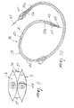
The reactor 6 is constituted by two surfaces, a thermally-conducting
one, which is arranged in contact with the pouch 5, and another surface that
is arranged in contact with the internal wall 3b, this arrangement of the
reactor 6 being essential in order to detect the temperature of the pouch 5.
The reactor 6 comprises an enclosure 27, which is closed and divided
into a first compartment 28, which contains a first component C1, and into a
second compartment 29, which contains a second component C2 suitable to
react with the first component with an exothermic or endothermic reaction
and is separated from the first compartment 28 by a tearable membrane 30,
at least one of the first and second compartments 28 and 29 respectively
containing the first and second components C1 and C2 substantially in
vacuum.
The reactor 6 further comprises means for inserting a tool 31 for
tearing the membrane 30: said insertion means are constituted by an inlet 32
and are provided with retention and sealing means, which are suitable to
prevent the outflow of the first and second components C1 and C2 and the
inflow of the air that is present outside the enclosure 27 and are constituted
for example by an insert 33 made of elastic/elastomeric material, which is
accommodated in the inlet 32 and is suitable to be crossed by the tool 31
and to close the opening formed therein by said tool.
The first component C1 is in the form of a loose solid, such as
particles, granules or the like, and is for example suitable to dissolve with an
exothermic reaction in the second component C2, which is in fluid form.
The first component C1 can be constituted for example by calcium
chloride and the second component C2 can be constituted for example by
water; however, alternative embodiments are not excluded in which the first
component C1 and the second component C2 have a different chemical
nature.
The enclosure 27 comprises a first bag 34 or the like, the interior of
which forms the first compartment 28, and a second bag 35 or the like,
which has walls at least partially constituted by the membrane 30 and is
accommodated within the first bag 34, its inside forming the second
compartment 29.
The first and second bags 34 and 35 are made of a material of the
flexible type and are mutually associated proximate to a portion of their
walls at which the inlet 32 is formed.
The enclosure 27 and more specifically the first bag 34 comprises at
least one heat-conducting portion, which is suitable to be placed in contact
with the pouch 5.
Advantageously, the reactor 6 is coupled to the pouch 5 by way of
anchoring means 36; in particular, it is arranged so as to overlap the pouch 5
with the heat-conducting portion of the enclosure 27 (first bag 34) in contact
with said pouch.
The anchoring means 36 are for example of the type of adhesive tapes
37, straps or the like; as an alternative, the reactor 6 and the pouch 5 can be
packaged so as to mutually overlap inside a single containment bag, which
is not shown. The tool 31 is of the type of a needle or the like.
Further, the kit 1 comprises withdrawal and conveyance means 38 for
withdrawing and conveying the fluid from the pouch 5 to a patient.
The withdrawal and conveyance means 38 comprise a duct 39, which
is constituted by a first tubular element 40 for the flow of the fluid and by a
second tubular element 41 that provides a sheath and has a substantially
larger diameter than the first element, said elements being inserted in each
other so as to be substantially coaxial, the gap 42 formed between them
being suitable to act as thermal insulation.
A piercing element 43 is associated with the inlet end 39a of the duct
39 and can be inserted in a coupling 44 of the pouch 5 after removing the
associated protection seal, while at the outlet end 39b of the duct 39 there is
an associated injection element 45, such as a needle, catheter or the like, for
injection into the patient.
The inlet end 39a and the outlet end 39b of the duct 9 are provided
with respective stiffening sleeves 46 reinforced by a spiral reinforcement 47
that is suitable to avoid kinking.
Conveniently, the display and/or graduated scale of the first and
second indicator means 23 and 26, respectively for the sensed temperature
and pressure and/or the duct 39 and/or the sleeves 46 and/or their
reinforcement 47 are made of a material that is visible even in conditions of
poor ambient visibility, such as fluorescent or bright material or the like.
The bag 2 comprises loops 48 for the passage of the cable 22 of the
temperature probe 20 and of the duct 39, said loops being formed on the
outer wall 3a of the first pocket 3 and/or in the flap 7.
Further, the bag 2 is provided with one or two shoulder straps 49,
which are provided with adjusting means 50 for adjusting their length, and
with coupling means for coupling to an element for hanging, such as a slot
51 formed at its top.
Finally, the bag 2 comprises containment/anchoring means for
containing and/or anchoring the first and second sensing and indication
means 18 and 19 and the tool 31, which can be constituted for example by
compartments 52 (for the cable 22), cases 53, which are advantageously
transparent (for the first indicator means 23), straps 54 or elastic rings 55
(for the tube 16, the pressure gauge 24, the tool 31).
In practice it has been found that the described invention achieves the
intended aim and objects.
The invention thus conceived is susceptible of numerous
modifications and variations, all of which are within the scope of the
appended claims.
All the details may further be replaced with other technically
equivalent ones.
In practice, the materials used, as well as the shapes and the
dimensions, may be any according to requirements without thereby
abandoning the scope of the protection of the appended claims.
The disclosures in Italian Patent Application No. MO2004A000074
from which this application claims priority are incorporated herein by
reference.
Where technical features mentioned in any claim are followed by
reference signs, those reference signs have been included for the sole
purpose of increasing the intelligibility of the claims and accordingly, such
reference signs do not have any limiting effect on the interpretation of each
element identified by way of example by such reference signs.