Cross-Reference to Related Applications
-
This is a continuation-in-part of U.S. Patent Application Serial No.
08/527,519, filed September 13, 1995, U.S. Provisional Application Serial
No. 60/023,572, filed August 19, 1996, and U.S. Provisional Application
Serial No.
filed August 30, 1996.
Field of the Invention
-
The invention relates to systems which assist with the movement
of patients who are partly or completely incapacitated. The invention
more particularly relates to systems which give a single health care worker
the capability to move a patient from one bed to another bed, between a
bed and a cart or gurney, between a sitting and a standing position or
between a slumped position in a chair or bed and a more elevated
position.
Background of the Invention
-
Health care workers at hospitals, nursing homes, and home care
programs face the challenge of moving partly or completely incapacitated
patients. A typical patient weighs between 45 and 90 kilograms, although
many others weigh much more. Consequently, at least two to four health
care workers are usually needed to move the patient. These activities
often create unacceptable risks of injury, almost without regard to the
number of health care workers used in the patient transfer. The risks are
particularly high when a sufficient number of workers is not available to
assist in a patient transfer. For example, injuries to workers' backs account
for approximately 50% of worker's compensation costs for workplace
injuries in the health care industry in the United States, and thus are a
particularly vexing problem.
-
Patient transfers can be placed in several broad categories. A first
category includes the horizontal transfer of a patient from one flat surface
to another. A second category involves upright transfers where a patient
is moved from a horizontal position to an upright or sitting position in a
wheelchair, chair or commode, and the return of the patient to the
horizontal position from an upright or sitting position. A third category of
transfer relates to the positioning or movement of patients in order to
change their position in a bed or chair, for example pulling the patient up
in the bed or rolling the patient from side to side. Although many
attempts have been made to devise improved systems for patient transfer,
almost all of these transfers continue to be manually performed.
-
Current healthcare guidelines typically recommend that four health
care workers participate in a patient transfer. Two workers are at the bed
side and two workers are at the cart side. Each worker grabs an edge of a
draw sheet, which is positioned under the patient. The patient is then
transferred between the bed and the cart through a combination of lifting,
pulling, and pushing. An elongated plastic sheet is often placed beneath
the patient to reduce friction or drag. Since a health care worker has to
bend over at the waist to accomplish these patient transfers, the stresses
encountered are magnified well beyond what would otherwise be expected
for a maximum recommended lift of approximately fifty pounds.
Normally this recommended maximum lift is measured with the lift at or
near the worker's center of mass. Extremes in a health care worker's
height, either taller or shorter than average, or any weakness in either the
arms or legs further exaggerate these risks.
-
Many hospitals have swing-type mechanical lift devices to assist in
certain patient transfers. However, these devices are not widely used
because they are often cumbersome and time-consuming to set up and
operate. Depending on the lift required, the devices may also be
inappropriate.
-
The upright transfer and positioning categories provide similar
difficulties, especially if the patient is unable to cooperate. For example,
weak and elderly patients reclining in a semi-erect position tend to slide
down. These patients must be returned to a position more toward the
head of the bed. To do so, two health care workers usually grasp the
patient by the upper arms to hoist the patient toward the head of the bed
after the bed has been lowered to a more horizontal position. This manual
transfer often causes strain on the workers' upper and lower backs and
possible contact bruises on the patient. Similar difficulties occur with
upright transfers.
-
Given these formidable difficulties, there have been other attempts
to mechanize the patient transfer process. For example, U.S. Patent
2,665,432 (Butler), describes a cart with a manual crank connected to an
extensive pull unit. The pull unit has a large number of straps which
connect at an edge by hooks to a transfer sheet. Rotation of the crank
winds the pull unit onto a roller. The size of the pull unit presents many
difficulties including its attachment at many locations to the sheet and the
awkwardness of winding it on the roller. The pull unit must be placed
under the patient just prior to transfer, since it would not normally be kept
there otherwise. Also, no means are provided for transferring the patient
off the cart.
-
U.S. Patent 2,827,642 (Huff) describes a similar system mounted to
the head of a bed and designed to move a patient from the foot toward the
head of the bed. The '642 Patent does not describe the process of moving a
patient laterally from one horizontal surface to another.
-
U.S. Patent 4,970,738 (Cole) discloses another patient transfer system
which employs a manual crank and self-locking gear system. This system
has an advantage over the system described in the '432 patent in that the
transfer is reversible. Rotating the crank drives a belt system, which is
attached to a semi-rigid transfer apron. The apron is thereby transferred
horizontally while supporting a patient. This system has the disadvantage
that the apron must be first positioned under the patient before the patient
can be transported from a bed onto a cart. Another disadvantage is that the
transfer support alone does not provide sufficient support for the patient
or the transfer system. Because of the complexity of its design,
considerable operator interaction would be required for the transfer
support to be mounted to a cart and then operated to transfer a patient.
-
U.S. Patent 2,733,452 (Tanney) describes a transfer system that uses a
motorized pulley to transfer a patient on a metal-reinforced transfer sheet.
The transfer sheet has metal grommets in its corners for attachment to
cables. A motor is used to wind the cables onto reels thereby resulting in
the transfer of the sheet and the patient thereon. However, the patient
must first be moved onto the transfer sheet before being moved from a bed
to the cart. Moreover, this invention fails to provide support beneath a
patient being transferred thereby.
-
U.S. Patents 4,747,170 and 4,868,938 (both to Knouse) reveal a
motorized winch-type transfer system. This transfer system has apparent
advantages over the transfer system of the '452 patent, which include a
more secure transfer sheet gripping mechanism and the use of a transfer
sheet which does not need grommets or other similar devices. Though
more secure, the gripping system is difficult and awkward to use.
-
U.S. Patent No. 5,038,424 (Carter et al.) teaches a system for
reciprocally transferring a patient between a bed and a cart. This system
employs a pliable transfer web wound about two detachable, cylindrical
rollers and a drive motor mounted on the bed and the cart. In use, the bed
and cart are positioned side-by-side and the web is placed beneath the
patient. The roller adjacent the cart or bed onto which the patient is to be
transferred is detached. While unwinding a sufficient length of transfer
web wound thereon, the roller is extended to the opposite side of the bed
or cart onto which the patient is to be transferred, and there connected to
the drive motor. The drive motor is then activated, thereby rewinding the
transfer web onto the roller and transporting the patient disposed thereon.
Thus, while enabling reciprocal transfer, the system of the '424 patent is
time consuming and awkward to set up. Moreover, as in the previous
inventions discussed hereinabove, the patient is not supported adequately
while being transferred.
-
While considerable effort has gone into developing horizontal
patient transfer systems, all of the systems previously developed have
significant drawbacks. These drawbacks primarily relate to the significant
difficulties encountered in set-up and operation.
-
The patent described hereinabove primarily relate to systems for
transferring patients from one horizontal surface to another horizontal
surface. By partial contrast , U.S. Patents 4,700,415 and 4,837,873 (both to
DiMatteo et al.) teach a system for transferring patients between a reclined
wheelchair and a bed. The bed is equipped with a sheet wound about a
right side roller and a left side roller, the sheet positioned beneath a patient
reclining thereupon. The right and left side rollers are positioned laterally
on each side of the bed, usually slightly below the plane of the patient.
Two corner rollers are situated above the right side and left side rollers and
approximately level with the top surface of the bed. The reclined
wheelchair is equipped with two articulated rollers. Extending between
these rollers is a sheet, the sheet including three bands. The lateral edges
of the sheet may be joined or separate. If the lateral edges are to be joined,
the sheet spans above and below the wheelchair upper surface. If the
lateral edges are free, the sheet spans the wheelchair upper surface, its ends
wound about the two rollers. The separate transfer systems for the bed and
wheelchair must be powered such that both sheets rotate with equal
velocities. In use, the patient reclining upon the bed is conveyed laterally
by the bed transfer system. Upon encountering the wheelchair transfer
system, the patient is thereupon further conveyed onto the wheelchair.
The wheelchair may then be further adjusted, allowing the patient to
assume a sitting position.
-
While the system of DiMatteo allows for transfer to or from a
reclining wheelchair and for adjusting the wheelchair between sitting and
reclining positions, its shortfalls include the complexity of its design, the
need to retrofit beds with the rollers and sheet provided, and the
possibility of pinching the patient or catching clothing in the gaps between
the bands.
-
U.S. Patent 3,597,774 (Warren) describes a harness and winch
mechanism for raising a patient reclining upon a bed. The winch is
mounted to a post attached to the head of the bed and is operated by a hand
crank. The harness loops under the patient's armpits such that excessive
stress may be applied thereto during operation of the device.
Summary of the Invention
-
The invention includes devices for transferring patients which
greatly simplify, and provide enhanced versatility over, any known
device. The adoption of these transfer devices will likely reduce the wide
incidence of back injuries in health care workers. A first system for the
horizontal transfer of patients is adapted to use existing transfer sheets and
an appropriately modified cart. The sheet is readily attached to a clamping
device close to the patient. The clamping device has a releasable catch
which holds the sheet. One or more straps are attached to the clamping
device, and the other ends of the straps are attached to reels that are part of
a winch. Activation of the winch winds the straps onto the reels. In a
highly portable embodiment of this transfer device, the entire apparatus
may weight only about 8-15 kilograms, and may be readily attachable and
removable to bed and cart rails.
-
A long narrow rectangular cushion can be placed between the bed
and cart when using the portable transfer device. The cushion is,
optionally, the length of the bed, and may be partially coated with a low
friction surface. The cushion may have fasteners for attachment to a bed
or cart, or it may also be configured to hang from the side of the bed or cart
by the fasteners when not in use. The cushion is particularly convenient
when used with a portable transfer device of the invention because no
other modifications to the bed or cart may be needed.
-
Other embodiments of horizontal transfer devices facilitate the
transfer of the patient by providing some lift to the patient as well as
horizontal motion. The vertical and horizontal transfer mechanisms may
both be operably attached to a single bed or cart frame. One embodiment of
a horizontal transfer mechanism within the invention has a transfer
element that moves within tracks. Another embodiment of a horizontal
transfer system of the invention moves the patient on a modularized
cushion. In other embodiments, lift is added by use of a harness which
provides significant advantage in distributing the weight of the patient
without the need to lift the patient to place a portion of the harness under
the patient. The harness has a support that goes across the patient's upper
body. Another portion of the harness goes under the patient's arms. The
harness has a fastener that attaches a lift mechanism near the back of the
patient's head.
-
An improved patient transfer system is capable of transferring a
patient using only a single attendant. The transfer system includes patient
transfer means for transferring the patient, a transfer sheet, a retaining
member assembly operably coupled to the patient transfer means and a
contact element assembly.
-
The improved transfer system may also include a highly portable
transfer unit. The portable transfer unit may be totally self-contained or
may be installable on a bed or cart and connectable to a separate clamp.
The portable transfer unit may utilize a plurality of detachable spools, as
well as means for sensing the proximity of a patient being transferred and
means for discontinuing the transfer in response to the sensing.
-
The improved transfer system may still further include a transfer
bridge support means for supporting a patient being transported when the
patient spans the bed or cart. The transfer bridge support means may be
foldable and may include a stabilizer, a cross sectional camber and a
leading edge camber to further prevent the transfer bridge support means
from being displaced during patient transfer, and improved slip-resistant
features.
Brief Description of the Drawings
-
- Figure 1 is a perspective view of a bed with an adjacent cart adapted
with a first embodiment of a horizontal patient transfer system;
- Figure 2 is a front, schematic view of a cart adapted with the first
embodiment of a horizontal patient transfer system with side rails in a
lowered storage position;
- Figure 3 is a front, schematic view of a cart adapted with the first
embodiment of a horizontal patient transfer system with side rails in a
raised patient transport position;
- Figure 4 is a front, schematic view of a cart adapted with the first
embodiment of a horizontal patient transfer system with one side rail in a
raised position and a second side rail in a bridge position used during
patient transfer;
- Figure 5 is a front fragmentary view of one embodiment of hinges
supporting a side rail;
- Figure 6 is an exploded view of a side rail of the first embodiment of
a horizontal transfer system;
- Figure 7 is a cut away view of a second drive system within the side
rail;
- Figure 8 is a perspective view of a first embodiment of a clamping
device useful with a first embodiment of the horizontal transfer system in
an orientation to be clamped to a transfer sheet folded over a rod;
- Figure 9 is an end view of a first embodiment of the clamping
device;
- Figure 10 is a perspective view of a second embodiment of the
clamping device;
- Figure 11 is an end view of the second embodiment of the clamping
device;
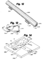
- Figure 12 is a perspective view of a third embodiment of the
clamping device;
- Figure 13 is an end view of the third embodiment of the clamping
device;
- Figure 14 is a perspective view of the attachment of a portable
horizontal transfer device for the transfer of a patient from one horizontal
surface to another;
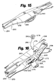
- Figure 15 is a perspective view of the portable horizontal transfer
device;
- Figure 16 is an exploded view of the portable horizontal transfer
device;
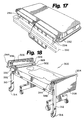
- Figure 17 is a perspective view of a portable cushion attached to a
horizontal surface to provide a smooth continuous surface for the transfer
of a patient with the portable horizontal transfer system, with the cushion
in a lowered, stored position shown in phantom lines;
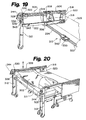
- Figure 18 is a perspective view of a further embodiment of a
horizontal transfer system;
- Figure 19 is a partial, cut away perspective view of the further
embodiment of the horizontal transfer system showing the drive system
for horizontal extensions;
- Figure 20 is a perspective view of the further embodiment of the
horizontal transfer system with a patient elevated over a cart to indicate
the ranges of motion obtainable by the transfer system;
- Figure 21 is a perspective view of the further embodiment of the
horizontal transfer system with an alternative design for the horizontal
drive;
- Figure 22 is a fragmentary perspective view of a sheet clamp
indicating its motion relative to a lifting support and its attachment to a
transfer sheet;
- Figure 23 is a perspective view of a bed equipped with the further
embodiment of the horizontal transfer device with the bed in a raised
position;
- Figure 24 is a partial perspective view of one end of the
embodiment of Figure 21 with an arrow showing the disengagement of a
removable panel;
- Figure 25 is a partial perspective view of one end of the
embodiment of Figure 21 with a removable panel attached as a shelf;
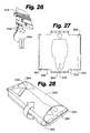
- Figure 26 is a perspective view of a portion of the foot board bed or
cart adapted with the further embodiment of the horizontal transfer
system indicating a location for the attachment of a control unit;
- Figure 27 is a top view of a transfer sheet designed for use with the
further embodiment of the horizontal transfer system;
- Figure 28 is a perspective view of the transfer sheet of Figure 27
shown in its folded position;
- Figure 29 is perspective view of an alternative embodiment of the
horizontal transfer system;
- Figure 30 is a perspective view of a portion of the alternative
embodiment of Figure 29 showing extendable horizontal supports;
- Figure 31 is a perspective view of the alternative embodiment of
Figure 29 being used to assist a patient to sit up;
- Figure 32 is a perspective view as in Figure 31 indicating the
rotation of a lifting element;
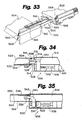
- Figure 33 is a perspective view of a transfer system with a horizontal
transfer mechanism;
- Figure 34 is a cut away side view of one embodiment of a docking
mechanism;
- Figure 35 is a cut away side view of a second embodiment of a
docking mechanism;
- Figure 36 is a perspective view of the transfer system of Figure 33
with a transfer element bridging between a bed and a cart;
- Figure 37 is a perspective view of a transfer bridge used with the
transfer system of Figure 33;
- Figure 38 is a perspective view of the transfer bridge of Figure 37
with the bridge in the bridging position;
- Figure 39 is a side view of the transfer bridge in the bridging
position with lever and rods removed;
- Figure 40 is a side view of the transfer bridge in the raised position
with lever and rods removed;
- Figure 41 is a perspective view of a split transfer bridge;
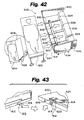
- Figure 42 is a perspective view of a mattress transfer system;
- Figure 43 is a perspective view of a docking mechanism used with
the mattress transfer system of Figure 42;
- Figure 44 is a perspective view of a gripping mechanism of the
mattress transfer system in pushing position;
- Figure 45 is a perspective view of a gripping mechanism of the
mattress transfer system in pulling position;
- Figure 46 is an exposed, top perspective view of a mattress and fixed
cushion of the mattress transfer system indicating the location of
structures within and below the mattress and cushion;
- Figure 47 is a perspective view of a mattress transfer system used
with a position changing cart and a folding mattress;
- Figure 48 is a perspective view of the mattress transfer system and
position changing cart depicting the cart in a folded position;
- Figure 49 is a side view of the position changing cart in the chair
orientation;
- Figure 50 is a perspective view of a lobster claw type of bed jacket
being placed on one side of a person;
- Figure 51 is a perspective view of the bed jacket in place around a
person;
- Figure 52 is a perspective view of the bed jacket secured around a
person and hooked to a hoisting mechanism;
- Figure 53 is a perspective view of a motorized bed jacket attached to
a stand above a wheel chair;
- Figure 54 is a front view of a padded vest;
- Figure 55 is a perspective view of the padded vest around a person
and attached to a tether where hidden portions of the vest are depicted
with phantom line;
- Figure 56 is a perspective view of a motorized bed jacket being
attached to a mount above a headboard;
- Figure 57 is a top perspective view of the motorized bed jacket;
- Figure 58 is a partial cut away view of the drive system of the
motorized bed jacket;
- Figure 59 is a perspective view of a bed jacket attached to three
hoisting mechanism on a ceiling using a three way control cylinder;
- Figure 60 is a side perspective view of the three way control
cylinder;
- Figure 61 is a schematic view of the internal components of the
three way control unit;
- Figure 62 is a top right perspective view of another clamp
embodiment of the present invention;
- Figure 63 is a side plan view of the clamp of Figure 62, in an open
position;
- Figure 64 is a side plan view of the clamp of Figure 62 in a closed,
locked position;
- Figure 65 is a top perspective view of another clamp embodiment of
the present invention, the clamp disassembled and depicted in an
exploded view;
- Figure 66 is a top perspective view of the clamp of Figure 65
assembled;
- Figure 67 is a top plan view of another clamp of the present
invention;
- Figure 68 is a side plan view of the clamp embodiment of Figure 67;
- Figure 69 is another embodiment of the transfer system of the
present invention, whereby a patient may be bidirectionally transferred
without the necessity of reinstalling this embodiment on another bed or
cart;
- Figure 70 is a side plan view of the embodiment of Figure 69,
wherein a patient is being transferred away from the bed on which the
embodiment is installed;
- Figure 71 is a side plan view of the embodiment of Figure 69,
wherein a patient is being transferred onto the bed or cart onto which the
embodiment is installed;
- Figure 72 is a top, side perspective view of a remote control usable
for any of the embodiments described herein;
- Figure 73 is a top, side view of a remote control, which may be used
for any of the embodiments described herein;
- Figure 74 is a top, side perspective view of a portable transfer device
and clamp installed onto a hospital bed;
- Figure 75 is a top, side perspective view of an embodiment of the
portable transfer device, wherein a spool or reel may be detachably
installed onto a drive shaft;
- Figure 76 is a side plan view of any of the portable transfer devices
of the present invention depicting a reel for winding a retraction belt,
wherein an automatic cutoff device is operationally installed;
- Figure 77 is another embodiment of a portable transfer device
installed onto a bed, and wherein one of the clamps of the present
invention is connected thereto by means of belts;
- Figure 78 is a side view of any of the portable transfer devices of the
present invention, depicting a mounting bracket and quick release pin;
- Figure 79 is a top perspective view of another portable transfer
device of the present invention;
- Figure 80 is a top perspective view of a detachable remote control for
any of the portable transfer devices of the present invention;
- Figure 81 is a fragmentary top perspective view of a portable transfer
device of the present invention, depicting a clip for securing the jaws
therein;
- Figure 82 is a fragmentary top perspective view of a portable transfer
device of the present invention, depicting a lock-down device for securing
the jaws thereto;
- Figure 83 is a top plan view of a portable transfer device of the
present invention, depicting the downwardly opening jaw portion of the
clamp thereto;
- Figure 84 is a side plan view of a portable transfer device of the
present invention, depicting an upwardly opening jaw portion thereof;
- Figure 85 is a top plan view of a motor and winch system, suitable
for any of the transfer devices of the present invention;
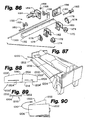
- Figure 86 is an exploded view of the motor and winch assembly of
Figure 85;
- Figure 87 is a top front perspective view of a transfer bridge
spanning a gap between a bed with a patient reclining thereon and a
transfer cart;
- Figure 88 is a bottom plan view of an alternate embodiment of the
transfer bridge of Figure 87;
- Figure 89 is a fragmentary side view of the transfer bridge of Figure
87 or Figure 88, depicting the hinge thereon;
- Figure 90 is a top front perspective of the bridge of Figure 87 being
folded and prepared for either transport or storage;
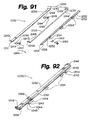
- Figure 91 is an exploded view of a clamp of the present invention;
- Figure 92 is a top perspective view of the assembled clamp of Figure
91;
- Figure 93 is a side perspective view of a portable transfer unit;
- Figure 94 is a side plan view of the portable transfer unit of Figure
93; and
- Figure 95 depicts an attendant carrying a portable transfer unit.
-
-
These figures are intended to be merely illustrative and nonlimiting.
Detailed Description of the invention
-
The invention includes improved devices and methods for moving
patients and other individuals who lack full mobility. Patients must be
moved in a variety of ways while providing care in various locations,
including hospitals, nursing homes and other residences. For example,
patients may need to be transferred horizontally between a bed and a cart,
they may need to be repositioned in a bed or chair, or they may need to
assume a prone, sitting or standing position. The unifying feature of the
various embodiments of this invention is the enablement of empowering
a single health care worker to now be able to move a patient in a
substantially low risk manner to either the patient or the healthcare
worker. The embodiments of this invention further allow a patient
transfer event to require between about 20 seconds and 28 seconds and
preferably about 24 seconds.
-
A feature of the horizontal transfer systems of the present
invention includes a support beneath the patient and a mechanical or
electro-mechanical system for applying a horizontal force to the support to
effect the transfer. The design of the various embodiments incorporate
varying features to achieve this utility. In order to reduce cost, the
simplest systems are designed to be adapted for use with beds, carts and
transfer sheets now commonly in use in health care facilities. Other
embodiments optimize the particular characteristics of the design with less
regard to adaptation to existing equipment. In all cases, each design
focuses toward the goal of a safe and efficient patient transfer event by a
single health care worker, or greatly reducing the number of healthcare
workers required for each transfer event.
-
The embodiments of the present invention described hereinbelow
are also taught in U.S. Provisional Application Serial No. 60/023,572, filed
August 19, 1996, and in U.S. Provisional Application Serial
No. filed August 30, 1996, and with the entire contents of
each being hereby incorporated by reference.
-
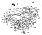
Referring to Figure 1, the first embodiment of the horizontal
transfer system 100 includes a standard patient cart 102 retrofitted with a
horizontal transfer mechanism 104. The cart 102 will generally have a base
106 with four wheels 108. The wheels 108 preferably have lock levers 110
for applying brakes that prevent the rotation of the wheels 108. The base
106 may have a top surface 112 that usually, but not necessarily, will have a
flat portion 114.
-
Cart 102 has a support portion 116. The support portion 116 is
attached to the base by one or more upright supports 118. The
embodiment represented in Figure 1 has two upright supports 118. Some
designs may have the wheels 108 attached directly to the upright supports
118 eliminating the need for a base 106. The support portion will
preferably have cushioned bumpers 120. The cart 102 can have the
capability of raising and lowering the support portion 116 relative to the
base 106 and other features. The support portion 116 provides a support
structure 122 for supporting a cushion or mattress 124 for holding a patient
126.
-
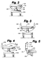
Horizontal transfer mechanism 104 includes two side rails 128.
Referring to Figure 5, the side rails are mounted to the cart 102 with hinges
130 and 131. The side rails 128 and hinges 130 are preferably adapted from
existing side rails and hinges on the cart 102. The hinges 130 can adjust to
place the side rails 128 in either an elevated pull position or a lowered
storage position. Preferably, hinges 131 are used to place the side rails 128
in a horizontal bridge position to provide support and a smooth surface
for transferring the patient. The different positions are schematically
depicted in Figures 2-4. Alternative designs for the side rail can allow for
the side rail to slide straight down to a lowered position, and other
variations are possible.
-
Each side rail 128 has a handle 132, a control panel 134 and two
openings 136 for a power assembly, such as winch 138. Other numbers of
openings can be used for access to the winch unit. The control panel 134
has a plurality of switches 140 to control the operation of the winch 138.
The particular design of the side rail 128 and control panel 134 can be
varied without effecting their function.
-
Referring to Figure 3, a convenient structure for the side rail 128 has
a frame 142, winch 138, a front cover 144 and a back cover 146. The frame
142 has extensions 148 attached to frame substructure 150 at frame hinge
152. The frame substructure 150 has a winch mounting portion 154. The
frame substructure 150 is preferably made from metal, a rigid polymer or a
composite material, although other materials exhibiting the proper
strength, weight, and cost characteristics may be suitable. The back cover
146 has open portions 156 for the passage of extensions 148 and motion of
frame hinges 152 as well as a portion of handle 132 and openings 136. The
outer surface 147 of back cover 146 (Figure 2) is a transfer surface that
preferably is made from a very low friction material to assist with the
transfer process and reduce the risk of injury. Front cover 144 has parts of
handle 132 and openings 136, and control panel opening 158.
-
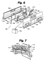
The winch 138 is coupled to control panel 134 by wires 160. A
conventional manual winch can also be used without excess difficulty, but
less conveniently. The drive system 142 preferably has at least one motor
162 and can use a variety of conventional designs. The motor may directly
rotate the drive shaft as depicted in Figure 6. Referring to Figure 7, the
motor 162 rotates a first drive shaft 164 which has a first gear 166. First gear
166 engages a second gear 168 which preferably has a larger diameter than
first gear 166 so that the rotation of the motor 162 is reduced. Second gear
168 is connected to a second drive shaft 170.
-
Two belts 172 each with a clip 174 are attached to the second drive
shaft 170 at positions aligned with openings 136. The belt preferably winds
on spools 175 which help ensure that the belts 172 wind and unwind
straight. The belts 172 are preferably made from very strong synthetic
fabric such as the material used in seat belts for automobiles. The winch
138 can be powered by a battery pack 176 utilizing power cord 178.
Alternatively, winch 138 can be powered by alternating current using a
power cord (not shown). Cart 102, or any other embodiment of the present
invention, may also include aligning and docking mechanisms. Aligning
mechanisms include powering and steering means, whereby at least two of
the wheels of cart 102 are powered and steered by operation of control
switched 140. Docking mechanisms include clamps and electromagnets,
also operated by control switches 140, and which secure cart 102 to the
horizontal surface on which the patient is to be transported is disposed. In
addition to control switches 140, hand-held remote control units
communicating with the control mechanism of cart 102 by electric or
electromagnetic means are within the scope of the present invention.
Voice actuated controls are also within the scope of the present invention,
thereby enabling the patient, as well as an attendant, to begin and
discontinue a transfer event.
-
Cart 102, or any other embodiment of the present invention, may
further include means for sensing an asynchronous operation of the
transfer mechanisms. Such means include sensing the individual belt
torque or drag experienced when belts 172 are being retracted and a
comparison of these sensings. A difference between sensings exceeding a
predetermined value or a sensing ratio greater than or less than a
predetermined ratio range would result in an alarm being actuated or an
automatic discontinuance of transfer to be effected.
-
Cart 102 of Figure 1 is designed for use with a standard patient draw
sheet 190. The standard patient draw sheet 190 is sufficiently wide so that
it can be folded over the patient 126, if desired, but typically not long
enough so that it rests under the head or feet of the patient. Rather than
using several people to move the patient with the draw sheet 190,
horizontal transfer mechanism 104 performs the comparable function.
Clips 174 can be designed to attach directly to draw sheet 190, but it is
preferred to use clamping device 194 to provide a more even pull over the
length of the sheet 190 and smoother motion to the patient. For
particularly tall patients, the draw sheet 190 can be wrapped around patient
126 for added support of the patient, and both ends of the sheet are
attached to clamping device 194.
-
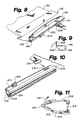
Three embodiments of the clamping device 194 are presented in
Figures 8-13. In the first embodiment shown in Figures 8 and 9, clamping
device 194 can be used to attach draw sheet 190 to winch 138 employing rod
192. A U-shaped portion 196 forms a cavity 198 which is covered by a
spring loaded gate 200. Rod 192 can enter the cavity 198 when pushed
against the gate 200. Force from the rod 192 against the gate 200 from
inside the cavity 198 tends to force the gate 200 closed thereby preventing
the withdrawal of the rod 192. Gate 200 has an upward extension 202.
Forward force on the upward extension 202 opens the gate 200 for the
withdrawal of rod 192 from cavity 198. Clips 174 are conveniently
attached to the clamping device 194 at J-shaped flanges 204. Rod 192 can be
optionally tethered to the clamping device 194 at one or more positions for
convenience, and the rod 192 can be clipped to the clamping device 194 for
storage.
-
In the second and third embodiments, the clamping device 194 has
an upper portion 206 and a lower portion 208 attached at a hinge 210 to
form a cavity 212. The front of the cavity 212 is closed by an L-shaped,
hinged closure 214. The two embodiments differ in their design of J-shaped
flanges 216 or 218 for the attachment of clips 174. In these two
embodiments, the sheet 190 is directly placed into the cavity 212 without
the need to wrap the sheet 190 around a rod 192, although a rod 192 could
still be used if desired. The sheet is held in place by the L-shaped hinge
closure. A thin rigid tucking device (not shown) of any convenient length
can be used if desired to assist with tucking the sheet into the clamp.
-
Clearly, a variety of other designs for clamping device 194 are
possible within the general concepts presented. For all of these
embodiments, any portion of the sheet can be attached, not just the end of
the sheet. This is important because the clamping device should,
preferably, be placed as near as possible to the patient so that the transfer
mechanism 104 can fully transfer the patient onto the second horizontal
surface from the first.
-
In operation, the cart 102 is wheeled up to a patient's bed 220, as
depicted in Figure 1, or another cart. The side rail 128 facing the patient's
bed 220 is placed in the bridge position with the low friction surface 147
directed upward. The draw sheet 190 is attached to a clamping device. The
belts 166 are unwound from drive shafts 164 so that they are long enough
to reach rod 192 at the edge of the bed 220. The belts are unwound either
by activating the motor to unwind the belts or by using a clutch to allow
the belts to be freely withdrawn from the drive shaft. The clips 174 on the
ends of the belts 166 are attached to a clamping device 194 and the
clamping device 194 is engaged by the rod 192 and sheet 190. Other
embodiments of the clamping device can be used with or without the rod
192.
-
The appropriate switch 140 mechanism is actuated, and the winch
138 begins winding the belts 166 onto the drive shafts 164 (Figure 6). The
motor 162 should be designed to apply a slow, steady and constant force to
move the patient 126 without jerking or applying any other inappropriate
forces, or provide variable speeds of movement consistent with gradual
starts and stops and safe transfer throughout travel. The draw sheet 190
helps to distribute the forces over significant areas of the patient's body.
When the patient 126 is on the cart's cushion 124, the motor 162 is turned
off or otherwise disengaged. At this point, the belts 172 are disconnected
from the clamping device 194, and the sheet 190 is removed from the
clamping device.
-
In order to transfer a patient from a cart to a bed, the bed would
have to be adapted with a similar winch as described on cart 102. This bed-based
transfer device would preferably be adapted with the side rails of a
conventional bed. These side rails may go up and down rather than
folding under the bed. The winch could easily be adapted on one or both
sides of the bed, and may be retrofitted to a bed in a comparable fashion as
a cart, based on the above description.
-
Alternatively, a portable winch unit readily carried by a single
health care provider can be used to replace the winch on the bed, on the
cart or both. One embodiment of such a portable winch unit 250 is shown
in Figures 14-16. The portable winch unit 250 includes a housing 252, a
clamping device 254 and a winch 256. The clamping device 254 serves to
hold a transfer sheet 190 in the same way as clamping device 194 in the
first embodiment of the horizontal transfer device 100. The clamping
device 254 also serves as a frame or a portion of the frame for the portable
winch unit 250. The housing 252 preferably has a top portion 258 and a
bottom portion 260 which are preferably heavy plastic shells surrounding
the clamping device 254 and the winch 256, although other materials can
be used.
-
The winch 256 includes a motor 262 that can rotate a drive shaft (not
shown) connected to a reel 263. Belt 264 winds around reel 263. Belt 264 is
comparable to belts 166 in embodiment 100. The free end of the belt 264
has a handle 266. Handle 266 attaches to a clamp 268 rigidly attached to the
edge of a bed or cart. The clamp 268 can be designed to fold out of the way
when not in use. The belt 264 passes out of housing 252 through an
opening 270. The operation of winch 256 can be controlled through a
circuit board 272 which is connected to motor 262 by wire 274. Circuit
board 272 can be similarly connected to a port 276.
-
A control unit 278 with switches 280 can be connected to port 276 by
way of tether 282. The operator can operate the winch 256 using control
unit 278. Alternatively, control switches 280 can be made integral with the
housing 252, as shown in Figure 15, but this would be less desirable
because the operator would have to lean over the bed or cart while the
patient was being transferred. Control unit 278 can have a wireless
connection with circuit board 272 using a transmitter/receiver (not
shown). Winch 256 is powered by a standard wall outlet using a cord 284.
A retractable cord assembly 286 is preferably used to keep the cord out of
the way when not in use and to prevent excess cord being in the way
during the transfer of the patient. Alternatively, a battery, preferably
rechargeable, can be used to power the winch.
-
Referring to Figure 14, to transfer a patient from a first bed/cart 288
to a second bed/cart 290, a draw sheet 190 is used under the patient in the
same way as in the first embodiment 100. A portable cushion 292 can be
placed between the first bed/cart 288 and the second bed/cart 290 to a
relatively smooth continuous surface for transferring the patient, as
shown in Figure 17. Straps 294 with a hook and loop fastener can be used
to attach the portable cushion 292 to the bed or cart when not in use. The
portable cushion 292 can be used with other transfer devices or even as an
aid during manual transfer. The cushion 292 would preferably have a top
surface with a very low friction which is preferably made from a plastic
material.
-
The portable winch unit 250 is attached to draw sheet 190 using
clamping device 254, as shown in Figures 15 and 16. The design of the
clamping device 254 can be similar to the clamping devices in Figures 8-13
or a comparable design based on similar concepts. The draw sheet 190 can
be wrapped over a rod 192 (Figure 8) for attachment to the clamping device
254. Referring to Figure 14, belt 264 is withdrawn from housing 252 so that
handle 266 can be attached to clamp 268. Clamp 268 is rigidly attached to
the second bed/cart 290 on its side opposite the side near the first bed/cart
288. Clamp 268 can be optionally reversibly detachable or lowerable to
storage position. The operator uses control unit 278 to activate the motor
262. As the motor 262 retracts belt 264, the portable winch unit 250 and the
patient are drawn toward clamp 268 which result in the patient being
moved onto second bed/cart 290.
-
Referring to Figure 14, the transfer devices of the present invention,
especially the clamps, are designed to be centered at the patient's center of
gravity when the patient is in a supine position. A patient's center of
gravity is usually about midway between the patient's navel and buttocks,
represented as lines N and B, respectively. Thus, for transfer to move the
patient smoothly and evenly, the clamp center of gravity (represented by
arrow C) should be aligned about midway between lines N and B on the
patient.
-
A further embodiment of a horizontal transfer system 300 involves
a specially designed transfer sheet 302 and a transfer unit 304, as shown in
Figure 18. Since the transfer unit 304 can move a patient in either of two
directions, horizontal transfer system 300 has the advantage that only
either the cart or the bed must be supplied with a transfer unit 304, not
both. Therefore, the cart or bed not adapted with the transfer unit 304 can
be conventional.
-
The transfer unit has a head frame 306 and a foot frame 308 attached
to a drive system 310. The head frame 306 replaces or attaches to the head
board of the bed or cart while foot frame 308 replaces or is attached to the
foot board of the bed or cart. The head frame 306 and the foot frame 308
each have at least one vertical support 312 with a wheel 314 at the bottom
of the vertical support 312. The wheels 314 should be oriented to roll
along the direction defined by the width of the bed/cart. The wheels 314
can be attached to the vertical support 312 in a way that permits shifting of
the wheels out of contact with the floor so that the bed or cart can be
moved without interference from the wheels 314. The vertical supports
312 can have a removable brace (not shown) extending between the two
vertical supports 312 to help compensate for the forces created by the
weight of the patient.
-
Referring to Figures 19-21, the head frame 306 and foot frame 308
each have at least one expandable horizontal support 316 extending from
the vertical supports 312. The expandable horizontal supports 316 have
fixed portions 318 that are attached to the head(foot) board or the
head(foot) board portion 320 of the head(foot) frame 306 (308). Fixed
portions 318 of the expandable horizontal support 316 typically would
extend at least across the width of the bed or cart. Telescoping portions 322
of expandable horizontal support 316 are attached to a vertical support 312
and slidably engage a corresponding fixed portion 318. In certain
embodiments, the telescoping portion 322 will slide into the
corresponding fixed portion 318, although other types of slidable
engagement are possible.
-
The head frame 306 and the foot frame 308 each have a lifting
support 324. The lifting support 324 is attached in a way such that it moves
with the vertical support 312 and the telescoping portions 322. Each lifting
support 324 has a gripping portion 328 and generally two lifting portions
330. The gripping portion 328 has an opening 332 into which sheet clamp
325 can be withdrawn using cables 327, as shown in Figure 22. Sheet clamp
325 can grasp transfer sheet 302. Referring to Figure 23, cables 327 permit
sheet clamps 325 to remain attached to transfer sheet 302 while the
mattress support 329 goes through a range of motion. In a preferred
configuration, one lifting portion 330 engages vertical support 312 at a slot
336. Another lifting portion 330 engages moving support 338 which is
attached to a telescoping portion 322.
-
The lifting support 324 is capable of a range of vertical motion. The
range of vertical motion will typically be between 6 inches and 12 inches.
The range of vertical motion gives enough clearance for the horizontal
transfer from a first bed/cart to a second bed/cart. In other words, the
retrofitted bed/cart 326 with its attached transfer unit 304 can transfer
patients from or to the retrofitted bed/cart 326. The vertical lift is also
convenient for the changing of linens, although the transfer sheet would
need to be changed separately.
-
Referring to Figure 19, the drive system 310 includes a horizontal
drive system 340 and a vertical drive system 342. The drive system 310 is
operated from a control panel 344 (Figures 18-20) that is located on vertical
supports 312 or a portable controller 346 (Figure 23) that is patched into the
head frame 306 or foot frame 308 through connector 348. Other
arrangements for the control of the drive system 310 are possible. The
drive 342 for the vertical motion of the lifting support can be adapted to
operate by any conventional motor or hydraulic system, such as a
motorized worm drive 343.
-
Two embodiments are shown for horizontal drive system 340 in
Figures 19 and 21 respectively. The first involves a motor 350 fastened to
the bottom of the bed/cart frame 352. The motor turns drive shafts 354
which go to a transmission 356 which transfers the rotation of the drive
shaft to lateral motion of a telescoping portion 322 of an expandable
horizontal support 316. The second embodiment of the drive system has a
motor 358 mounted on either the head frame 306 or the foot frame 308.
The motor 358 rotates a worm drive 360 that is mounted horizontally
along side of the motor 358. The worm drive 360 transfers motion to a
telescoping portion 322 of an expandable horizontal support 316. An
optional removable panel 362 can be removed, as shown in Figure 24 and
mounted on the foot frame 308 where it can be used as a shelf or
cardiopulmonary resuscitation (CPR) board for additional equipment as
shown in Figure 25.
-
An appropriate transfer sheet 302 for use in this embodiment of the
horizontal transfer unit 300 is depicted in more detail in Figures 27 and 28.
The transfer sheet 302 has wings 380 with hook and loop or comparable
fasteners 382 at the edges of the wings 380. The wings 380 can be folded
over the patient and closed with fasteners 382. The shape of the wings can
be selected as desired. The top and bottom of transfer sheet 302 can have
reinforced attachment portions 384 optionally with reinforced holes,
grommets 334, or other improved attachment means. Alternatively, the
sheet can be attached to the sheet clamps 325 similar to the attachment of
the sheet to the clamps shown in Figures 8-13. Having grommets on the
sheet can be a disadvantage during the washing process. The attachment
portions 384 will generally extend to or just beyond the end of the mattress
386. Other designs are possible for the sheet, for example a version that
does not fold over the patient.
-
Referring to Figures 19 and 20, in operation, the vertical supports
312 and the telescoping portion 320 of horizontal supports 316 are initially
placed in their retracted position if the patient is being moved from the
retrofitted bed/cart 326 and are initially placed in their extended position if
the patient is being moved from a separate bed/cart 327 to the retrofitted
bed/cart 326. The transfer sheet 302 is optionally folded over the patient,
and the fasteners 382 are secured. Attachment portions 384 are placed into
opening 332, and sheet clamps 325 engage reinforced holes 334. At this
point, the vertical drive system 342 originally in its lower point is engaged
to its upper point to raise the patient into a suspended position.
-
The horizontal transfer system 300 is engaged accordingly to move
the patient from an original location to the transfer location. If the patient
was originally on the retrofitted bed/cart 326, the vertical supports 312 and
the telescoping portion 320 move to their extended position, and if the
patient was not originally located on the retrofitted bed/cart 326, the
vertical supports 312 and the telescoping portion 320 move to their
retracted positions. Once the horizontal transfer is complete, the vertical
drive system 342 is lowered and the transfer sheet 302 is disengaged.
-
Another embodiment of a patient transfer device 400 is shown in
Figure 29. Head portion 402 and foot portion 404 are similar in
construction to head frame 304 and foot frame 306 respectively except that
head portion 402 and foot portion 404 lack lifting supports 324 attached to
the telescoping portion 320 and have instead top supports 406 which
support upper transverse support 408. The upper transverse support 408
provides support to counter the forces from the weight of the patient.
-
Upper transverse support 408 has transverse tracks 410 on both sides
of upper transverse support 408 which support lifting elements 412.
Lifting elements 412 have track wheels 414 which rotate within the tracks
410 yielding transverse motion of the lifting elements 412. Lifting
elements 412 contain winches (not shown) for retracting cords 416. Cords
416 have fasteners 418 at their ends for attaching to reinforced holes or
grommets 420 at the corners of a draw sheet 422. Retraction of cords 416
raises draw sheet 422 which contains a patient secured within the sheet
422.
-
As shown in Figure 30, extendable horizontal supports 424 operate
similarly to extendable horizontal supports 314 to allow the lateral motion
of the vertical supports 426 on wheels 428 along with upper transverse
support 408 and lifting elements 412. As with the previous embodiment
system 300, the alternative embodiment device 400 can move a patient
from the retrofitted bed/cart to a second bed/cart or from a second bed/cart
to the retrofitted bed/cart.
-
Alternatively, referring to Figures 31-32, a single lifting element 412
can be used along with a lift jacket 430. Lift jacket 430 fits around the torso
of a patient. Fasteners 418 attach to loops 432 on lift jacket 430. When
attached to a lift jacket 430, retraction of cords 416 lifts the patient's torso off
the bed into a bent position at the patient's waist. The lifting element 412
can then be translated and rotated as shown in Figures 31 and 32 to place
the patient in a seated position at the side of the bed. The patient's back is
supported in this position. In this way the horizontal transfer device 300
serves a second purpose in assisting a patient into a sitting position from a
supine position on a bed.
-
A transfer system 500 designed for retrofitting of both the bed 502
and the cart 504 is depicted in Figure 33. The transfer system 500 includes a
horizontal transfer mechanism 508 and a transfer bridge 510 (Figures 37-41).
The horizontal transfer mechanism includes a docking mechanism
506. Figures 34 and 35 depict two representative embodiments of the
docking mechanism 506. The first embodiment has a spring loaded clamp
512 with arms 514. Arms 514 protrude from an opening 516 at the side of
the foot board 518 of bed 502. Spring loaded clamp 512 engages a cavity 520
opening into transfer bar 522. When the angled front edge 524 of the arms
514 engage cavity 520, the arms 514 deflect towards each other against the
spring (not shown) other until tips 526 clear flanges 528 at which point the
arms return outward as tips 526 engage flanges 528. Arms 514 pivot on a
docking support 530 within the bed foot board 518. The head boards (not
shown) have a comparable docking mechanism. When the clamp 512 is
protruding from opening 516, the arms can be disengaged by pressing arms
514 together.
-
In the second embodiment of the docking mechanism 506 depicted
in Figure 35, a gear 538 supported by a docking support 540 protrudes from
an opening 542 in the side of the bed foot board 544. Protruding gear 538
engages teeth 548 in the top surface 550 of cavity 552 within transfer bar
522. Gear 538 can flex slightly on its support 540 to engage the teeth 548.
Cavity 552 within transfer bar 522 does not have flanges at its opening.
The gear 538 is disengaged by pressing downward on docking support 540
when docking support 540 is protruding from opening 542. Again, the
head boards (not shown) have a comparable docking mechanism.
-
The two embodiments of the docking mechanisms 506 are described
in a particular configuration with respect to the cart and the bed. This
configuration can be reversed with the bed holding the protruding gear 532
or clamp 512. In either configuration, the protruding gear or clamp can be
retracted by the worm gear drive 532 when docking is being performed.
-
The horizontal transfer mechanism 508 includes a transfer element
556 and a drive system 558. Transfer element 556 has a gripping
mechanism 560 for gripping a transfer sheet such as transfer sheet 302 in
Figures 27 and 28 and transfer bar 522. The gripping mechanism 560 is
attached to transfer bar 522 by a plurality of support bars 564. Gripping
mechanism 560 can be similar to sheet clamp 325. Transfer bar 522 moves
within cart channel 566 and bed channel 568. Support bars 564 slide
within slots 570 and 572 within cart channel 566 and bed channel 568
respectively. The docking supports 530 or 540 can be moved laterally by
drive system 558 which can comprise a worm gear drive 532. The worm
gear drive 532 has a motor 534 and a worm 536. The rotation of worm 536
moves the docking supports 530 or 540. The motion of the docking
supports 530 or 540 moves the transfer bar 522 within channels 566 and
568. The worm gear drive 532 can move the transfer bar 522 in either
direction to effect the movement of the patient in either direction.
-
Transfer bridge 510 is mounted on the side of cart 504. Transfer
bridge 510 has a bridge 574, lever 576 and mounting portions 578. Bridge
574 is preferably molded from a low friction material such as, for example,
polypropylene, to facilitate the passage of the transfer sheet. It is
recognized that other low friction materials may also be suitable.
Mounting portions 578 are attached to the side of the cart 504 by rods 580.
Mounting portions 578 have a hinge 582 which supports bridge 574. Lever
576 passes through mounting portions 578. Rotation of lever 576 changes
the configuration of hinges 582 thereby moving bridge 510 between a
stored position and a bridge position, as shown in Figures 37-40. In the
bridge position, bridge 574 fills in the gaps between the bed 502 and cart 504.
In the storage position, the bridge 574 acts as a side rail for the cart 504.
Figure 41 depicts a slightly different embodiment of the transfer bridge 510
having a split transfer bridge 584. These embodiments of the transfer
bridge can be adapted for use with other transfer systems including the
conventional manual transfer system.
-
To transfer a patient between the bed 502 and cart 504, the transfer
sheet 302 is attached to the gripping mechanisms 560 at the head and foot
of the patient's resting place, similar to the attachment of transfer sheet 302
in the embodiment of Figure 18. Referring to Figure 36, the cart 504 and
bed 502 are positioned to align channels 566 and 568. Referring to Figure
38, the transfer bridge 510 is placed in its transfer position to fill the gap
between the bed 502 and the cart 504. As shown in Figure 36, the drive
system 558 is engaged to move the transfer element 556 from the bed 502
or cart 504 where the patient was located to the bed 502 or cart 504 where
the patient is being transferred. Once the patient is transferred, the cart 504
and bed 502 are undocked, and the transfer sheet 302 is disconnected from
the gripping mechanisms 560.
-
The above transfer systems rely on supporting the patient on some
type of sheet during the transfer. While relying on a sheet is similar to
often used present methods with health care personnel providing the
transfer forces, supporting the patient on a sheet may be inappropriate for
patients with certain injuries. For these patients it would be safer to
transfer the entire mattress or cushion, as described below.
-
Figure 42 displays a bed 600 including a mattress transfer system 602.
The bed 600 supports a modular mattress 604 and a fixed cushion 606. The
modular mattress 604 has wing 608 of padded fabric that wraps around
fixed cushion 606 to form a smooth surface without any gaps, as shown in
the insert of Figure 42. Wing 608 tucks under the modular mattress 604
when not in use. Referring to Figure 43, bed 600 connects with cart 610 by
way of a docking mechanism 612 when the mattress 604 is to be
transferred. The docking mechanism 612 has one or more apertures 614
for accepting projections 616. Figure 43 displays apertures 614 on bed 600
and projections 616 on cart 610, but the opposite arrangement would work
similarly. It is possible to have a locking mechanism (not shown) to lock
projections 616 in apertures 614 to prevent relative motion of the bed 600
and cart 610 when the modular mattress 604 is being transferred, but the
same effect can be accomplished by locking the wheels of the cart 610.
-
In one embodiment, the mattress transfer system 602 has a
transverse bar 618 connected to a plurality of lateral bars 620 and at least
one lateral drive bar 622. Lateral bars 620 slide along lateral tracks 624
while lateral drive bar 620 engages lateral drive track 626. The lateral bars
620 and lateral drive bars 622 allow the transverse bar 618 to extend just
past the edge of bed 600. Transverse bar 618 has a plurality of gripping
mechanisms 628. Each gripping mechanism 628 has a pushing position
(Figure 44) and a pulling position (Figure 45) for pulling and pushing the
modular mattress respectively.
-
Referring to Figures 42 and 46, the gripping mechanisms 628 grip
handles 630 near the edge of modular mattress 604. The mattress transfer
system is controlled from a control panel 632 mounted on the foot board
634, as shown in Figure 42. Operation of the mattress transfer system 602
moves the transverse bar 618 either toward or away from cart 610 by
moving the lateral drive bar 622 accordingly. Of course, a variety of
designs are possible for the mattress transfer system 602 besides the
embodiment described.
-
Referring again to Figure 46, the modular mattress 604 has a
channel system 636 to accommodate the transfer system 602. The channel
system includes a transverse void 638 to accommodate transverse bar 618
and longitudinal channels 640 to accommodate the lateral tracks 624 and
lateral drive tracks 626. Handles 630 are located along the upper surface of
transverse void 638. To the extent necessary, fixed cushion 606 may also
have appropriate channels 642.
-
In order to transfer the modular mattress 604, the cart 610 is first
docked with bed 600 using docking mechanism 612. If the modular
mattress is being moved to the cart 610, the patient is centered on the
modular mattress 604, and the gripping mechanisms 628 are set from
control panel 632 in their pushing position. The mattress transfer system
602 is operated to move the transverse bar 618 toward cart 610. When the
mattress is located on cart 610, the docking mechanism 612 is disengaged.
-
If the modular mattress 604 is being moved from the cart 610 to the
bed 600, the cart 610 and bed 600 are docked appropriately. Then, the
transverse bar 618 is placed in its extended position within transverse void
638. The gripping mechanisms 628 are placed in their pulling position.
The mattress transfer mechanism 602 is operated to move transverse bar
618 away from cart 610. When the modular mattress 604 is in position on
bed 600, the mattress transfer system 602 is stopped, and the docking
mechanism is disengaged.
-
The bed 600 with the mattress transfer system 602 can be adapted to
work with a position changing cart 650 when used with a folding mattress
652, as shown in Figures 44-47. The position changing cart 650 has a base
654 and a plurality of, preferably two, arms 656. Base 654 has a plurality of
locking wheels 658 providing a relatively broad base of support for cart 650.
The base should have sufficient weight and a relatively low center of mass
such that cart 650 is stable. The top 660 of base 654 provides support for the
center of folding mattress 652 when the mattress 652 is positioned on cart
650.
-
Arms 656 have a support portion 662 and a lever portion 664.
Support portions 662 extend laterally toward bed 600 from the far edge of
the cart 650. Lever portions 664 are rigidly attached to support portions 662
at one end and are attached to a hinge mechanism 666 at base 654. Support
portions 662 support folding mattress 652 when the mattress 652 is
positioned on cart 650. The folding drive within base 654 is operated from
a control panel 668 at the side of base 654. The folding drive operates to
rotate hinge mechanisms 666 to change the configuration of folding
mattress 652 from a prone configuration to a seated configuration as in
Figure 49 or visa versa.
-
When going from a supine to a seated configuration, the lever
portion 664 at the head of the mattress 652 rotates upward and the lever
portion 664 at the foot of the bed 400 rotates downward. Folding mattress
652 has creases 670 to accommodate the change in configurations. The
movement of the folding mattress 652 on and off of position changing cart
650 is analogous to moving the modular mattress 604 on and off of cart
610.
-
The next devices are designed to hoist or pull up a patient on a bed
or a chair. These systems are configured with at least one lifting device
and at least one winch system. In a first embodiment 700 of the hoist
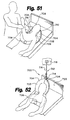
system, the lifting device is a lobster claw shaped bed jacket 702, as shown
in Figures 59-61. The bed jacket 702 has two claw portions 704 joined at
joint 706. Claw portions 704 are, in one embodiment, made of fabric
enclosing padding of some kind. Joint 706 involves folds in the fabric that
yield greater flexibility at the joint 706. The bed jacket 702 is easy to put on
the patient because no part of it fits under the mid-torso of the patient.
The lifting forces, however, are distributed across the patient's chest, while
the neck is supported by the claw portions.
-
Claw portions 704 have edges 708 at their ends opposite joint 706.
Edges 708 of opposing claws 704 can be joined by a hook and loop fastener
710, with clips (not shown), or other suitable fastener. The edges 708 do
not necessarily have to be joined in contact. In use, joint 706 is placed
across the patient's chest, and the claw portions are placed under the
patient's arms. Edges 708 are joined behind the patient's neck, if desired. If
the edges are not joined, they will still be held together by their attachment
at their respective ends to the same winch.
-
Bed jacket 702 can be used with at least two embodiments of the
winch system. In a first embodiment of the winch system 712, shown in
Figure 52, the bed jacket 702 has a loop 714 for the attachment of a tether
716. The tether 716 is attached to an external winch 718. Depending on its
intended use, the external winch 718 can be attached to a bed's head board
720, located on a support 722 elevated above a bed or wheel chair 724
(Figure 53) or mounted to a ceiling (Figure 52). External winch 718 can be
operated manually with a hand crank (not shown) or with a motor (not
shown) controlled by a control panel.
-
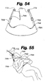
External winch 712 can also be used with padded vest 762 shown in
Figures 54 and 55. The padded vest 762 has the same advantages as the
lobster claw bed jacket 702. The padded vest 762 has a foam portion 764
that fits across the user's chest. Two adjustable straps 766 extend from the
foam portion 764. One strap 766 has a head support 768 attached. The free
end of the head support 768 is attached with a hook and loop fastener 770
or a comparable fastener to the other strap 766. Rings 772 attached to the
end of straps 776 attach the vest 764 to a tether 716 for connection to a
winch 718.
-
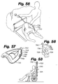
A second embodiment of the winch system 726 has a winch
mechanism 728 within the bed jacket 730 itself, as shown in Figures 53, 56-58.
The winch mechanism 726 is preferably motorized. The winch
mechanism 728 is embedded in one of the claws 732 of the bed jacket 730,
although the winch can be imbedded in other designs of bed jackets. The
preferred winch mechanism 728 has a motor 734 which rotates a drive
shaft 736 connected to a spool 738. Tether 740 is attached to spool 738 and
has a ring 742 on its end.
-
Controls which can be found on claw 732 include a release switch
744, a recoil switch 746, a pull switch 748 and a lower switch 750. The
release switch 744 releases the spool 738 so that the tether 740 can be pulled
from bed jacket 730. The recoil switch 746 winds up tether 740 on spool 738
using a spring mechanism (not shown) assuming that there is little
resistance on the tether 740. The pull switch 748 activates the motor 734 to
wind tether 740 on spool 738, and the lower switch 750 runs the motor 734
in the opposite direction releasing tether 740 from spool 738. Optionally,
the controls may be placed external to the bed jacket such as in a remote
control unit or mounted to the bed. The external control units would
communicate with the winch mechanism 728 either through a wired or
wireless (transmitter/receiver) communication similar to the control unit
for the embodiment in Figures 15 and 16.
-
The ring 742 can be attached to a head board, an elevated support on
a wheel chair or a ceiling mount such that the motorized bed jacket 730
can be used in the same way as the non-motorized counterpart. The
winch bed jacket combination 730 is more versatile because it can be used
in a variety of ways without the need for having a variety of separate
winches. Furthermore, the controls are conveniently located such that the
health care worker can operate the controls while being close enough to
the patient to assist in their motion.
-
Finally, bed jacket 702 can be connected by way of a three axis control
cylinder 752 to three ceiling mounted winches 754, as shown in Figures 59
and 60. The control cylinder 752 connects to bed jacket 702 by way of ball
756 which fits into a ball joint 758. Control cylinder 752 has three switches
760 controlling motion along one of three axes. Referring to Figure 61, the
switches 752 are connected to a microprocessor 753 which has been
preprogrammed with the locations of winches 754. The microprocessor
753 uses simple geometry to calculate instructions used to control winches
754 to perform the selected motions. Microprocessor 753 is connected to
winches 754 by way of wires 755. This versatile system can be used in a
variety of ways including transferring a patient from a bed 762 to a wheel
chair 764 or pulling a patient up in either a bed 762 or a wheel chair 764.
Padded vest 764 can also be used with a three axis control cylinder 752.
-
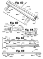
Figures 62-95 relate to features of a portable patient transfer system.
The system design, and each component thereof, is consistent with the
patient care and health care injury reduction goals stated above. Referring
to Figures 62-64, an engaging mechanism 800 is shown. Engaging
mechanism 800 is designed for engaging or clamping a sheet bearing a
patient. Engaging mechanism 800 includes forwardly opening element
802, arcuate engaging element 804, belt engaging element 806 and
cylindrical member 807. Elements 802, 804 are ideally elongated with a
length of at least greater than about 60 centimeters and preferably at least
about 100 centimeters (cm). Element 802 has an interiorly disposed
movable extension 808. A laterally disposed edge, such as convex edge 810,
is present on extension 808. Arcuate engaging element 804 has exterior
surface 812 and interior surface 814. Interior surface 814 defines cavity 816.
A plurality of belt engaging elements 806 are affixed to element 802 and
extend through engaging element 804. Disposed exterior to engaging
element 804 on belt engaging element 806 is at least one engaging slot 817.
Disposed on each end of element 802 is pivot means 818. Slidingly and
rotatingly affixed about pivot means 818 is pivoting member 820. Pivoting
member 820, in turn, is rigidly affixed to portions of cylindrical member
807. The exterior surface of cylindrical member 807 may be smooth or
ideally present a roughened surface to enhance gripping. A rubberized or
tacky substance may be present on the surface of cylindrical member 807, or
other means to either enhance gripping may be present using either a
surface area increase or greater gripping features of the existing surface
area. Also, a plurality of biasing springs or other biasing means (not
shown) are optionally disposed within engaging mechanism 800.
-
Functionally, elements 802, 804 of engaging mechanism 800 are
biased away from each other by means of biasing springs (not shown).
When a user desires to place a transfer sheet within engaging mechanism
800, the user first wraps a portion of the transfer sheet around cylindrical
member 807. Subsequently, cylindrical member 807 is pivoted proximate
convex interior surface 810. Elements 802 and 804 are then forced toward
each other by the user, thereby extending engaging slot 817 on belt
engaging element 806 away from element 804. When elements 802, 804
are in a closed position, cylindrical member 809 and the portion of the
transfer sheet wrapped around cylindrical member 809 are totally enclosed
within clamp 800. Finally, engaging slot 817 is sufficiently distant from
element 804 for belt buckle 822 to firmly latch onto belt engaging element
806. Belt buckles 822, when firmly attached onto engaging element 806,
thereby hold elements 802 and 804 in a closed position, simultaneously
enclosing cylindrical member 809 therein and exerting a gripping force on
the portion of the transfer sheet enclosed. When a patient is being
transferred, a transfer force is exerted on belt engaging elements 806
further forcing elements 802 and 804 toward each other and thus exerting
an additional, or further, gripping force on the transfer sheet disposed
therein.
-
As shown in Figures 65 and 66, clamp 830 is another embodiment of
the present invention. Clamp 830 includes large U-channel member 832,
small U-channel member 834, cylindrical member 836, a plurality of belt
engaging elements 838 and a plurality of cams 840. Large U-channel
member 830 includes outer surface 842, inner surface 844 and a plurality of
slots 846, each slot 846 optionally configured with a horizontal and a
vertical dimension. Small U-channel member 834 includes outer surface
848 and inner surface 850. U-channel members 832, 834 are at least about
60 cm and preferably greater than about 100 cm in length. Cylindrical
member 836 has a radial circumference sufficient to enable cylindrical
member 836 to fit within the confines of inner surface 846 with a transfer
sheet wrapped therearound. Preferably cylindrical member 836 has a
length substantially the same as U-channel members 832, 834. The outer
surface of cylindrical member 836 may be smooth, but is preferably
somewhat rough to facilitate gripping, as described above. Belt engaging
elements 838 are rigidly affixed to, and extend from, small U-channel
member 834. Disposed on each belt engaging element 838 is an engaging
means 852 as part of a cam attachment element 838.
-
Functionally, a transfer sheet (not shown) is wrapped around
cylindrical member 836. Cylindrical member 836 and the enwrapped sheet
is disposed proximate inner surface 850 of small U-channel member 834
adjacent belt engaging element 838. Belt engaging elements 838 are then
passed through slots 846. Large U-channel member 832 and small U-channel
member 834 are forced toward each other until cylindrical
member 836 and the enwrapped sheet contact inner surface 844 of large U-channel
member 832. At this point, the vertical notch component of slots
846 has served as a passageway for cam attachment elements 854. Cams
840 are then configured so as to lock members 832 and 834 together. Belt
buckles or equivalent attaching means (not shown) are then affixed to belt
engaging elements 838. As in previous embodiments, when a transfer
force is exerted on clamp 830, members 832 and 834 are further forced
together, thereby exerting an additional, or further, gripping force on the
transfer sheet disposed therein. Clamps 800 and 830 are preferably made
from resilient, rather stiff materials. Materials suitable would be various
gauges of metal or synthetic resins. Buckle mechanisms, similar to those
commonly used in automobiles, as well as the belts attached thereto, are
possible for use as one embodiment of attaching means of the present
invention.
-
Clamp 860, depicted in Figures 67 and 68, includes base member 862,
pivoting upper member 864, two locking levers 866, locking mechanism
868 and a plurality of belt attachment sites 870. Pivoting upper member
864 pivots onto base member 862, with a pivot site at the base of member
864 and coincident with locking mechanism 868. A rubberized substance
869 or other material with increased tack is preferably present on the inner
surfaces of base member 862 and upper member 864. A pair of locking
levers 866 is present atop base member 862 and proximate the pivotal end
of pivoting upper member 864. Locking mechanism 868 cooperates with
locking levers 866 to secure pivoting upper member 864 in a locked
position. Ideally, pivoting upper member 864 is biased in an open position
by such means as a leaf or helical spring. Ideally two belt attachment sites
870 are disposed adjacent to each locking lever 866.
-
In practice, a portion of a transfer sheet (not shown) is disposed
between base member 862 and pivoting upper member 864. Alternatively,
the transfer sheet may be wrapped around a cylindrical element or other
suitable member, and then placed between base member 862 and pivoting
upper member 864. Pivoting upper member 864 is then pressed toward
base member 862 until locking mechanism 868 locks, thereby securing base
member 862 and pivoting upper member in a closed, locked position with
the transfer sheet gripped securely therewithin. Alternatively, pivoting
upper member 864 and locking levers 866 may be mechanically connected
by a linkage or lever combination in which locking lever 866 is pressed
down by a user, thereby forcing pivoting upper member 864 down until
locking mechanism 868 securely locks base member 862 and pivoting
member 864 in closed contact. Finally, belt or strap 872 is affixed to clamp
860 by disposing hook 874 within the slots located at belt attachment sites
870.
-
As depicted in Figure 68, when transfer sheet 876 is secured within
clamp 860, base member 862 and pivoting upper member 864 are in a
closed and locked position, and belt 872 is retracted away from transfer
sheet 876, a transfer force is exerted onto transfer sheet 876 in the direction
of arrow 880. Due to the upper placement of belt attachment sites 870 and
the angular configuration of the bottom portion of clamp 860, a pivot
point is thereby formed proximate locking mechanism 868. This transfer
motion, thereby, tends to pivot upper member 864 upwardly and the
portion of clamp 860 proximate hook attachment site 870 downwardly,
thus rotating clamp 860 about the pivot point located proximate locking
mechanism 868 and as indicated in arrow 880. The angular orientation of
the portion of transfer sheet 876 secured within clamp 860 relative to the
remainder of transfer sheet 876 exerts a further gripping force thereon.
-
Patient transfer system 900, as depicted in Figures 69-71, broadly
includes bed 902, cart 904, motor-winch unit 906, perpendicular transfer
units 908, 910, 912, clamp 914 and a plurality of belts discussed below.
Although depicted as cart 904, a bed or other horizontal surface may be
used and be within the scope of the present invention. Motor-winch unit
906 is ideally attached to base 916 of bed 902. Attached to the upper frame
of bed 902 is perpendicular transfer unit 908. On adjoining cart 904,
another perpendicular transfer unit 910 is attached to the upper frame.
Finally, another perpendicular transfer unit 912 is attached to the lower
frame of cart 904. As shown in Figure 69, a pair of belts 918 may extend
generally upwardly and vertically from motor-winch unit 906 through
perpendicular transfer unit 908, finally extending horizontally on mattress
915. Belts 918 are then attached to clamp 914 in any manner such as
described herein. Alternately, belts 918 may proceed horizontally from
motor-winch unit 906 beneath bed 902 and cart 904 through perpendicular
transfer unit 912. Extending generally upwardly and vertically from
perpendicular transfer until 912, belts 918 pass through perpendicular
transfer unit 910, then onto mattress 917. On mattress 917, belts 918 may be
attached to a clamp such as a clamp of the present invention. Ideally,
motor-winch unit 906 is attached to bed 902 by means of rings extending
from housing 920. These rings 922 ideally enclose an upper portion of the
casters 924 on which bed 902 is mounted.
-
In use, bed 902 and cart 904 are aligned and are preferably secured
together. If a patient is to be transferred from bed 902 onto cart 904, clamp
914 is attached to a transfer sheet upon which the patient is disposed. The
belts attaching to clamp 914 have been routed under bed 902 and cart 904
then upwards, and then horizontally by means of perpendicular transfer
units 910 and 912. Once motor-winch unit 906 is activated, thereby
retracting belts 918, the transfer force exerted will transport the patient in
the direction of arrow 926 from bed 902 onto cart 904. Once the patient has
been transferred onto cart 904, motor-winch unit 906 is disengaged.
Alternatively, a sensing device may be attached to perpendicular transfer
unit 910. This sensing device may be either mechanical, electronic,
magnetic, optical or a combination thereof in its operation and may detect
the presence of the patient, the buckle, the belt portion proximate the
buckle, or the clamp within a predetermined distance from perpendicular
transfer unit 910. If the patient is to be transferred from cart 904 onto bed
902, belts 918 are routed through perpendicular transfer unit 908 and onto
mattress 915 where they are attached to clamp 914. Clamp 914 is then
securely attached to a transfer sheet upon which the patient is disposed.
Motor-winch unit 906 is then activated, thereby retracting belt 918 in the
direction of arrows 930 and thereby generating a transfer force upon clamp
914. The transfer force acts upon the transfer sheet upon which the patient
is disposed, thereby transferring the patient from cart 904 onto bed 902 and
thereby further, or additionally, gripping the transfer sheet secured within
clamp 914. Again, patient proximity sensing devices may be included in
perpendicular transfer unit 908 as discussed hereinabove. Perpendicular
transfer units 908, 910, and 912 may include either a pulley system or a
roller system onto which belts 918 are emplaced prior to a patient transfer.
Clamp 914 may be any of the clamps disclosed herein. Some exemplary
embodiments of motor-winch unit 906 are discussed in more detail
herein.
-
Referring to Figures 72-74, patient transfer system 940 is depicted.
Patient transfer system 940 broadly includes bed 942, portable transfer unit
944 and clamp 946. Bed 942 includes mattress 948 and side rail 950. Side
rail 950 may include a plurality of horizontal bars 951. Portable transfer
unit 944 includes housing 952, one or more belts 954, an equal number of
attaching means or buckles 956 and a motor-winch unit. Further included
in portable transfer unit 944 is mounting bracket 958 which will be further
described below. Finally, handle 960 on portable transfer unit 944 enables
an attendant to easily grasp and carry portable transfer unit 944 as desired.
Housing 952 is preferably a light weight, resilient plastic or other suitable,
light weight material. Portable transfer unit 944 has the advantage of being
light in weight, hence readily transportable by an attendant of virtually any
size and lifting ability with little likelihood of injury therefrom.
Preferably, portable transfer unit weighs between about 20 and 35 pounds.
More preferably, portable transfer unit weighs between about 15 and 25
pounds.
-
Figures 73 and 74 depict two, of many, possible embodiments (966,
968) of control units to control the operation of portable transfer unit 944.
Controls 970 of control units 966, 968 serve to operate portable transfer unit
944. Control unit 966 may communicate with portable transfer unit 944 by
means of electromagnetic radiation, more particularly by radio frequency,
or other means. Controls 970 include on/off simultaneous transfer power
control 974 and left and right transfer actuator controls 976, 977. Control
unit 968 communicates with portable transfer unit 944 by means of a cord
or other suitable connecting means. The cord is mechanically and
electrically attached to control unit 968 and is disposed on a spool or other
retaining means within portable transfer unit 944. This spool is biased so
that cord 974 winds thereon when control unit 968 is released by the
operator. Control units 966 and 968 are preferably housed in a recess
contained within portable transfer unit 944 when not in use. An
alternative to the control unit of the patient transporting system of the
current invention is via voice actuation. Voice actuation would enable
the patient to effect the patient's own transfer and to halt a transfer in
progress if the need to do so arose.
-
Figure 66 depicts another embodiment of a portable transfer unit
according to the teachings of the present invention. In this embodiment
shaft 978 extends from housing 952 laterally. Exposed shaft 978 facilitates
mounting of spools 980 thereon, with such spools providing means upon
which belts 982 are wound. Since shaft 978 is exposed, each spool 980 may
be easily and quickly detached from shaft 978, to facilitate cleaning and
disinfecting of both shaft 978, spool 980 and belt 982.
-
Portable transfer unit 944' is depicted in later Figure 93. In this
embodiment, a receiving cavity 962 is formed on the lateral portions of
housing 952'. Within cavity 962 is a drive shaft upon which spool 980'
may be reversibly mounted. Belt 988' is routed through slot 963 so that
buckle 956 may be used to engage a clamp. Finally, cap 964 may be used to
cover cavity 962 for various reasons.
-
Referring again to Figure 72-67, portable transfer unit 944 is secured
to a side rail 950 by means such as those described below. Bed 942 is then
placed beside a bed or cart onto which a patient is disposed upon a transfer
sheet. The transfer sheet is then secured with clamp 946, proximate the
patient, and belts 954 are extended from portable transfer unit 944 and
attached to clamp 946. Either control unit 966 or 968 is detached from
portable transfer unit 944 and used to actuate the motor-winch by means
such as on/off controls 974. Upon actuation of the motor-winch
mechanism, transfer unit 944 begins to wind belts 954 and thereby move
clamp 946, the transfer sheet, and the patient. The motor-winch assembly
ceases operation when the attendant operates control unit 966, 968 or
when the sensing device, described above, functions.
-
During transfer it is desirable that the longitudinal axis of the
patient be generally parallel to the longitudinal axis of the bed or cart onto
which transfer is to be effected. If not, the patient may not be transferred
completely onto the bed or cart and may require further manual
adjustment by the attendant, possibly obviating some of the advantages of
this system. Thus, left or right transfer actuator controls 976, 977 may be
used. For example, left control 976 is actuated, the belt 982, attached toward
the patient's head, continues to be wound and the other belt 982 either
ceases to be wound or winding slows considerably. In similar manner,
right control 977 is actuated, the belt 982 attached closest to the patient's
feet continues to be wound and the other belt 982 either ceases to be
wound or winding again decelerates.
-
When patient transfer is complete, much of patient transfer system
940 may be disengaged from the transfer sheet and detached from bed 942.
Belts 954 may then be retracted until attached clamp 946 is proximate
portable transfer unit 944. Control unit 968 (or 966) is then stowed within
a niche in portable transfer unit 944. The attendant then grasps handle 960
and carries portable transfer unit 944 and attached clamp 946 to another
location (Figure 95), or shows the unit on the cart or bed awaiting
subsequent use.
-
Another portable transfer unit, designated as unit 984, of the present
invention is depicted in Figure 76. In this embodiment, belt 988 is bound
onto spool 986. Spool 986, in turn, is detachably mounted onto bracket 990.
Bracket 990 is, in turn, mounted onto the back of housing 952. Bracket 990
includes upper member 992 and lower member 994. An automatic sensing
and motor disconnect may be included in this, as well as other,
embodiments. A sensing mechanism detects the presence of either the
patient, the clamp, or the terminus of an attached belt. Upon sensing one
or more of these phenomena, portable transfer unit 984 ceases to wind belt
988, thereby stopping or easing (slowing) patient transfer.
-
The portable devices, as well as the other devices of the present
invention, preferably also contain an automatic recording and/or display
mechanism 988, representatively shown in Figure 77. Mechanism 998
records each patient transfer event. Recording is via a print out of paper or
other means, or may comprise storage or transfer of relevant information
electronically. The stored information may then be transferred to a
computer or other device as desired. Relevant information with regard to
a transfer event may include the time of day, the patient's number and
name, the attendant's name and number, and the time length of the
transfer event. Other items, such as motor performance and torque
received by the motor-winch assembly, speed, acceleration, alignment, or
other parameters of the patient or the clamp when transferring the patient
might also be recorded.
-
Referring to Figures 77 and 78, patient transfer system 1000 broadly
includes bed 1002 and portable transfer unit 1004. Bed 1002 includes
mattress 1006 and side rail 1008. Portable transfer unit 1004 includes
housing 1010, control unit 1012, belts 1014 and an engaging mechanism,
such as clamp 1016. Belts 1014 and clamp 1016 include any of the
embodiments discussed herein. Portable transfer unit 1004 combines a
housing which encloses the motor and winch assembly and which is easily
and reversibly mounted onto side rail 1008. Mounting bracket 1018 may be
integral to housing 1010 of portable transfer unit 1004 and readily and
securely mounts onto side rail 1008. A side view of one embodiment of
mounting bracket 1018 is depicted in Figure 78. While shown as integral
to the embodiment of Figure 77, the concept depicted in Figure 78 is
applicable to any of the portable transfer units of the present invention.
Mounting bracket 1018 includes lateral arm 1018, engaging side 1020 of
portable transfer unit housing 1010, horizontal extension 1022 and
substantially vertical member 1024.
-
In use, portable transfer unit 1004 is situated onto side rail 1008 such
that the lower surface of horizontal extension 1022 rests on side rail 1008.
Pin 1026 is then inserted in opening 1027, extending through member 1024
and into a slot or receiving orifice 1028, securely fastening therein.
Mounting bracket 1018, thereby securely holds portable transfer unit 1004
onto side rail 1008 during a transfer event. Moreover, transfer unit 1004 is
easily detachable from side rail 1008 by removing pin 1026.
-
An end view of another embodiment of a portable transfer unit
1004' is depicted in Figure 94, where an alternate mounting bracket 1018' is
disclosed. Mounting bracket 1018' includes horizontal extension 1022'
extending integrally from housing 1010'. Extending generally vertically
from horizontal extension 1022' are fixed upper vertical member 1030 and
pivotally mounted, lower vertical member 1032. A locking mechanism,
actuated by cam lever 1034, is included. To install portable transfer unit
1004' on a bed with side rails 1008, portable transfer unit 1004' is tilted,
allowing upper vertical member 1030 to be disposed such that an upper
side rail is between member 1030 and housing 1010'. Lower vertical
member 1032, extended in an open position, allows portable transfer unit
1004' to be disposed in position and lower side rails 1008 to be disposed
proximate housing 1010'. Lower vertical member 1032 is pivoted to a
closed position, generally coaxial to that of upper vertical member 1030.
Finally, cam lever 1034 is pivoted into a locked position in the direction of
arrow 1036.
-
In Figures 79 and 80, another embodiment of a self-contained
portable transfer unit 1040 of the present invention is depicted. Portable
transfer unit 1040 broadly includes handle-control unit 1042, housing 1044,
clamp 1046, belt 1048, hook 1050, and locking devices 1052. Portable
transfer unit 1040 is self contained, containing both the belt, clamp, and
enclosed motor-winch assembly. The motor-winch assembly of portable
transfer unit 1040 is preferably totally enclosed within housing 1044. Belts
1048 may be extended to hook onto the framework of a bed or cart or they
may be retracted to a position almost completely within housing 1044.
Locking devices 1052 may be embodiments previously discussed with
respect to the clamps of the present invention. Handle-control unit 1042
may be detached during a transfer event. Handle-control unit 1042 ideally
includes controls 1056 disposed within housing 1058. Alternatively,
handle-control unit 1042 may include the controls depicted in Figures 73,
74 and discussed hereinabove. Belt 1054 physically and electrically
connects control unit 1042 to the remainder of portable transfer unit 1040.
Ideally, belt 1054 is mounted to a pulley within housing 1044. Such a
pulley-type mechanism is preferred so that cord 1054 is retracted unless
pulled away by a user. Clamp 1046 ideally opens downwardly to admit a
transfer sheet therein.
-
In use, portable transfer unit 1040 is placed onto a bed, onto which a
patient to be transferred is disposed upon a sheet. As shown in Figures 79-84,
locking devices 1052 are unlocked and the jaws of clamp 1046 are
separated. A portion of the transfer sheet is placed between the jaws of
clamp 1046, the jaws are then closed and locking devices 1052 locked. Belts
1048 are extended away from portable transfer unit 1040, across the bed or
cart onto which the patient is to be transferred and hooks 1050 are hooked
onto the bed frame. The attendant detaches handle-control unit 1042 and
then begins the transfer by actuating the motor-winch assembly. When
the patient has been transported onto the desired bed or cart, the attendant
turns the motor-winch off. The transfer sheet is then freed from clamp
1046 and hooks 1050 are unhooked from the bed and retracted within
housing 1044. Finally, handle-control unit 1042 is reconnected to portable
transfer unit 1040. The attendant then may carry portable transfer unit
away by grasping and holding handle-control unit 1042.
-
In Figures 81 and 82, several embodiments are shown for securing
the clamps of the present invention. Referring to Figure 81, clamp 1070 is
secured in a closed position by the operation of clip 1072. Clamp 1070
includes lower pivoting member 1074 and upper clamp member 1076.
Clamp 1072 includes free end 1078 and pivot 1080. When in an open
position, free end 1078 has been pivoted away from the body of clamp 1070
and lower pivoting member 1074 is pivoted away from upper clamp
member 1076. Functionally, a transfer sheet (not shown) is placed between
lower pivoting member 1074 and upper clamp member 1076, which are
then pressed together. Free end 1078 is then pivoted toward the body of
clamp 1070, finally, being snapped around the front thereof. A locking
mechanism is thereby actuated, locking lower pivoting member 1074 and
upper clamp member 1076 securely together and the sheet therewithin.
-
Clamp assembly 1088 includes clamp 1090 and locking assembly
1092. Clamp 1090 further includes upper pivoting clamp member 1094 and
lower clamp member 1096. Locking assembly 1092 includes handle 1098,
which actuates the locking mechanism of clamp assembly 1088. Handle
1098 is affixed to the remainder of locking assembly 1092 via an elongated
member. Handle 1098 and the elongated member are slidable within slot
1100. When clamp assembly 1088 is in an open position, upper pivoting
clamp member 1094 is pivoted away from lower clamp member 1096 and
handle 1098 is disposed toward rear edge 1102 of clamp 1090. In use, a
transfer sheet is placed between upper pivoting clamp member 1094 and
lower clamp member 1096 and they are pressed together, firmly securing
the transfer sheet within. Handle 1098 is then grasped by the attendant
and pushed away from rear edge 1102, thereby activating locking assembly
1092 and securing upper pivoting clamp member 1094 and lower clamp
member 1096 together in a secure, closed position.
-
Figure 83 is a side view of a self-contained portable transfer unit
1110. Portable transfer unit 1110 may include any of the self-contained
portable transfer units described herein. Included are upper clamp
member 1112 and lower pivoting clamp member 1114. When pivoted
between an open and a closed position, lower pivoting clamp member
1114 may be moved in either direction as indicated by arrow 1116.
-
Figure 84 depicts self-contained portable transfer unit 1120. In
addition to other features described for the self-contained portable transfer
unit embodiments herein, transfer unit 1120 broadly includes upper
pivoting clamp member 1122, lower clamp member 1124 and housing
1126. Venting 1128 is present within housing 1126. As indicated by arrow
1130 upper pivoting clamp member 1122 pivots upwardly toward an open
position or downwardly toward lower clamp member 1124 when in a
closed position. Venting 1128, present in housing 1126, facilitates air
exchange and, consequently, enhances cooling of the motor-winch
assembly within portable transfer unit 1120.
-
Figures 85 and 86 disclose one embodiment of motor-winch
assembly 1150 of the present invention. Motor-winch assembly 1150
broadly includes frame 1152, upon which are mounted motor bracket 1154,
control board 1156, hook 1158, right clutch bracket 1160 and left clutch
bracket 1162. Motor 1164 is operationally mounted on an upper portion of
motor bracket 1154. Gear 1166 (which in one embodiment is a 42-tooth
gear) is attached to a shaft (not shown) extending from motor 1164. Gear
1166, in turn, operably engages gear 1168 which is mounted onto shaft
1169. Also mounted on shaft 1169 are right clutch 1170 and left clutch 1172.
Right clutch 1170 is disposed within right clutch bracket 1160. Left clutch
1172 is disposed within left clutch bracket 1162. Spring 1174 is disposed
about right clutch 1170 and about left clutch 1172. Spring 1174, in turn, is
enclosed by spring cover 1176. Spring cover 1176 is attached to spring hub
1178. Spring hub 1178 is affixed to right clutch bracket 1160 and left clutch
bracket 1162. Finally, spool 1182 may be detachably disposed on the
outboard portion of shaft 1169. Motor-winch assembly 1150 is suitable for
providing the necessary power to operate the transfer units described
herein.
-
Optimized patient transfer requires smooth transition of the patient
from one platform to another. One means for achieving such
optimization is through use of a transfer bridge 1200, shown in Figures 87-90.
A modified transfer bridge 1200' depicted in Figure 87 differs from
transfer bridge 1200. Transfer bridge 1200 broadly includes one or more
sections 1202. A stabilizer 1204 is ideally present on the underside of each
section 1202. Where multiple sections are used, such sections 1202 are
joined by hinge 1206 (discussed hereinbelow), and stabilizer 1204 extends
generally perpendicularly from each section. Functionally, transfer bridge
1200 is placed between a bed or cart onto which a patient is lying and
another bed or cart onto which the patient is to be transferred. Stabilizer
1204 is disposed between the platforms, thereby securely holding transfer
bridge 1200 in place and preventing transfer bridge 1200 from being
displaced by patient contact during a transfer. After use, transfer bridge
1200 is folded along hinge 1206 for storage or transport to another location.
-
One embodiment of the construction of hinge 1206 is depicted in
Figure 89. Hinge 1206 is preferably manufactured as a "living hinge", i.e. a
hinge made by removing a narrow, linear portion of the material along a
portion of transfer bridge 1200 or transfer bridge 1200'.
-
Transfer bridge 1200', shown in Figure 88, includes a plurality of
sections 1202' and a stabilizer 1204', perpendicularly mounted on the
underside of each section 1202. As in transfer bridge 1200, hinge 1206 is
present and divides 1202. Leading edge 1210 is present on the portion of
transfer bridge 1200' opposite stabilizers 1204'. Although not depicted,
transfer bridge 1200 and 1200' may include one or more carrying handles.
The carrying handles may be attachable or integral or may be cutout
sections within sections 1202 or 1202'. Preparing transfer bridge 1200' for a
patient transfer is essentially done in an identical manner as preparing
transfer bridge 1200, the only exception being leading edge 1210 is oriented
toward the patient to be transferred.
-
Both transfer bridge 1200 and 1200' are preferably constructed of a
smooth polyethylene sheet material, which is generally about 1.5
millimeters in thickness. Alternatively, hinge 1206 may be reinforced
with a thin sheet of polyethylene on the underside of transfer bridge 1200,
1200'. Stabilizer 1204' may be centered about 7.5 centimeters from edge
1214. One embodiment of transfer bridge 1200' is preferably about 31
centimeters wide at hinge 1206 and tapering to about 25 centimeters in
width at each end. The cambered radius for a side section of transfer bridge
1200' is about 105 centimeters. The cambered radius for the leading edge of
transfer bridge 1200' is about 225 centimeters. The side camber insures that
leading edge 1210 will firmly contact the mattress on which the patient is
disposed, such that transfer bridge 1200' will not be displaced during a
patient transfer. The leading edge camber allows for a gradually increasing
amount of contact during patient transfer, rather than immediate total
contact. The gradually increasing contact also tends to allow the patient to
be pulled atop transfer bridge 1200', rather than fully abutting and possibly
displacing transfer bridge 1200'. Transfer bridge 1200' is most
advantageously positioned when leading edge 1210 is placed under at least
a portion of the patient.
-
In an average male patient, 90% of the patient's weight resides in
the portion between the patient's buttocks and shoulders. Hence, the
overall length of transfer bridge 1200 or 1200' should minimally provide
support therefor. Accordingly, preferred lengths for transfer bridge 1200 or
1200' include about 65, 120 and 173 centimeters, with the most preferred
length being 120 centimeters.
-
Yet another embodiment of an engaging means or clamp 1230 for
use with this invention is depicted in Figures 91 and 92. Clamp 1230
broadly includes U-channel member 1232 and pivot assembly 1234. Pivot
assembly 1234, in turn, includes pivot member 1236 and pivot rod 1238.
Disposed laterally on each end of pivot member 1236 is a pivot point
orifice 1240 and tab 1241. Preferably and symmetrically affixed to pivot
member 1236 is a plurality of belt engaging elements 1242. Each belt
engaging element 1242 generally includes a tongue section 1244 and a
planer member 1246. Each tongue section 1244 defines an engaging slot
1245 disposed therein. Tongue section 1244 and planer member 1246 are
joined in a stair step fashion. A pair of pivot rod brackets 1248 are laterally
attached to pivot member 1236 by means of a rivet or belt. Orifice 1249 is
defined by each pivot rod bracket 1248 and provides the opening through
which pivot point 1240 is disposed. At least one cylindrical member 1250
is affixed to each pivot rod bracket 1248. U-channel member 1232 includes
a plurality of slots 1252 and a plurality of brackets 1254. U-channel
member 1232 has leading edge 1256 and inner surface 1258 which will be
discussed hereinbelow. Mounted on brackets 1254 is a plurality of cam
levers 1260 and springs 1262.
-
Operationally, a transfer sheet 1263 is wrapped about cylindrical
member 1250. Cylindrical member 1250 and the enwrapped portion of the
transfer sheet 1263 are then pivoted in the direction of arrow 1264 until
brackets 1248 rest upon tabs 1241. Slots 1252 on U-channel member 1232
are aligned with belt engaging elements 1242. U-channel member 1232
and pivot assembly 1234 are then pressed together, thus allowing belt
engaging elements 1242 to pass through slots 1252 and protrude forwardly
therefrom. U-channel member 1232 and pivot assembly 1234 may be biased
away from each other by means of a plurality of springs. Also another
alternative embodiment of clamp 1230 employs a spring to bias cylindrical
member 1250 in an open position. Cam levers 1260 are then rotated over
pivot member 1246, thereby biasing pivot member 1236 against U-channel
member 1232 and cylindrical member 1250 firmly against inner surface
1258. Finally, a belt buckle may be affixed to belt engaging elements 1242.
Leading edge 1256 of U-channel member 1232 is preferably arcuate in
conformation, thereby allowing clamp 1230 to more positively be pulled
upon a transfer bridge during patient transfer, rather than abutting and
displacing the transfer bridge.
-
Various modifications and alterations of this invention will become
apparent to those skilled in the art without departing from the scope and
spirit of this invention.
-
Various features are defined by the following clauses:
- A transfer system for transferring a patient from a first platform to a
- Clause 1 second platform by a single attendant, the transfer system comprising:
- patient transfer means for transferring a patient;
- means for supporting the patient during a transfer;
- a transfer sheet;
- a retaining member assembly operatively coupled to the
patient transfer means; and
- a contact element assembly operatively disposed proximate
the retaining member assembly, the contact element assembly
cooperating with the retaining member assembly to releasably grip
the transfer sheet proximate the patient disposed upon the transfer
sheet, such that a transfer force is exerted by the patient transfer
means and such that the retaining member assembly and the
contact element assembly further grip the transfer sheet in response
to the transfer force and effectively transfer the patient from the first
to the second platform.
- Clause 2 The transfer system of clause 1, the contact element assembly further
comprising a first contact element, the first contact element at least
partially disposable within the retaining member assembly.
- Clause 3 The transfer system of clause 1, the contact element assembly further
comprising a second contact element cooperating with said first contact
element, so that the transfer system transfers a patient within a patient
transfer time of between about 20 seconds and 28 seconds.
Clause 4 The transfer system of clause 1,
the retaining member assembly including an elongated
member, the elongated member generally U-shaped in cross section,
the contact element assembly including two planar sections
integrally joined at a bend and pivotally affixed to the rigid member,
in which an edge of the contact element is biased toward an
inner surface of the retaining member. - Clause 5 The transfer system of clause 4, the patient transfer means including
a housing, a motor, a winch, at least one belt and a handle, the housing
disposed about the elongated member, the motor and the winch disposed
within the housing, the winch being in mechanical communication with
the motor, the belt being affixed to the winch, and the handle being affixed
to the belt.
- Clause 6 The transfer system of clause 5, the patient transfer means further
including a control unit disposed within the housing and in operable
communication with the motor.
- Clause 7 The transfer system of clause 4, the least one contact element further
including an elongated cylindrical element.
- Clause 8 The transfer system of clause 1, the patient transfer support means
including a transfer bridge.
- Clause 9 The transfer system of clause 1, the patient transfer support means
including a transfer bridge, the transfer support bridge with a cross
sectional camber and a leading edge camber.
- Clause 10. The transfer system of clause 10, the transfer support bridge further
including a hinge.
- Clause 11 The transfer system of clause 9, the transfer support bridge further including a stabilizer.
- Clause 12 The transfer system of clause 1,
the retaining member assembly including a substantially rigid
first member, the first member with a lateral interior cavity, a
substantially rigid second member with an extension disposable
within the cavity and a plurality of third members affixed to the
second member and slidably engaged to the first member,
the contact element assembly including a generally cylindrical
element pivotally attached to the second member, the cylindrical
element disposable within the cavity. - Clause 13 The transfer system of clause 12, the transfer means comprising a
plurality of belts, each belt with a first and a second end, each of the
plurality of third members attached to one of the plurality of belts and in
which attaching any of the belts cooperatively places the first, second, third
and cylindrical elements in a closed position.
- Clause 14 The transfer system of clause 13, each of the plurality of belts further
comprising an attachment mechanism affixed proximate the first end of
the belt for releasably attaching the belt to one of the third members.
- Clause 15 A transfer system for transferring a patient from a first platform to a
second platform by a single attendant, the transfer system comprising:
- a portable transfer unit, the portable transfer unit attachable
to a bed or a cart, the portable transfer unit including
a housing:
a plurality of brackets attached to the housing for
reversibly attaching the transfer unit to the bed or cart;
a motor disposed within the housing;
a rotary motion transferal system partially disposed
outside the housing and in mechanical communication with
the motor; and
means for winding the plurality of belts,
in which a rotary motion is generated by the motor and
transferred to the rotary motion transferal system, thence to
the belt winding means thereon;
patient transfer means for transferring a patient;
a retaining member assembly operatively coupled to a patient
transfer means; and
a contact element assembly operatively disposed proximate
the retaining member assembly and cooperating with the retaining
member assembly to releasably grip a transfer sheet upon which a
patient is normally positioned so that when a transfer force is
supplied by the motor to the retaining member assembly then the
patient is transferred from a first platform to a second platform. - Clause 16 The transfer system of clause 15, in which the belt winding means
comprising a plurality of detachable first spools, each first spool detachably
mounted on the rotary motion transferal system outside the housing and
attached to one of the plurality of belts proximate the second end thereof.
- Clause 17 The transfer system of clause 15, the portable transfer unit further
including a control unit in controlling communication with the motor
and in which the portable transfer unit weighs less than about 30 pounds.
- Clause 18. The transfer system of clause 15, further including first means for
discontinuing the rotary motion and means for detecting a patient
position, the first discontinuing means and the patient detecting means
being configured so that when the patient detecting means detects the
patient within a predetermined distance from the portable transfer unit
the discontinuing means discontinues the rotary motion.
- Clause 19 The transfer system of clause 15, further comprising means for
optionally and automatically recording a transfer event, the recording
means operatively disposed proximate the portable transfer unit.
- Clause 20 The transfer system of clause 15, further comprising means for
sensing asynchronous operation among the transfer mechanisms and
second means for deactivating the motor, the asynchronous operation
sensing means and the second motor deactivating means operatively
disposed proximate the housing and in which the second deactivating
means deactivates the motor when the asynchronous operation sensing
means senses an asynchronous operation.
- Clause 21 A method of transferring a patient disposed on a transfer sheet from
a first surface to a second surface, comprising the steps of:
- providing a transfer system, the transfer system including a
clamp;
- attaching the transfer sheet to the clamp proximate the
patient, the clamp releasably gripping the sheet; and
- actuating the transfer system thereby exerting a transfer force
on the clamp, the clamp thereby further gripping the sheet and
thereby transferring the patient from the first surface to the second
surface.
- Clause 22 The method of clause 21, further comprising the step of terminating
patient transfer when the patient occupies a predetermined place relative
to the transfer system.
- Clause 23 The method of clause 21, further comprising the step of automatically
terminating patient transfer when the patient occupies a predetermined
place relative to the transfer system.
- Clause 24 The method of clause 21, further comprising the step of aligning the
first surface with the second surface, the aligning step occurring before the
attaching step.
- Clause 25 The method of clause 24, further comprising the step of docking the
first surface to the second surface after aligning the first surface with the
second surface.
- Clause 26 A method of transferring a patient disposed on a transfer sheet from
a first surface to a second surface, each surface operatively attached to a
support structure and a patient retaining structure, the method comprising
the steps of:
- providing a transfer system, the transfer system including a
clamp attached to a portable transfer unit by at least one belt, each of
the at least one belt further attached to a spool, the spool windably
attached to the portable transfer unit;
- attaching the portable transfer unit to a structure and in
which the structure includes the support structure attached to the
first surface or the second surface and the patient retaining structure
attached to the first surface or the second surface;
- disposing a portion of the transfer sheet within the clamp, the
portion of the transfer sheet proximate the patient;
- releasably locking the transfer sheet within the clamp, the
clamp thereby exerting a gripping force on the transfer sheet; and
- actuating the portable transfer unit, thereby winding the at
least one belt on the at least one spool, thereby exerting a transfer
force upon the clamp, the clamp, thereby exerting a further gripping
force on the transfer sheet disposed therein and thereby transferring
the sheet and the patient thereon from the first surface to the second
surface.
-