EP1583913B1 - Collapsible nut - Google Patents
Collapsible nut Download PDFInfo
- Publication number
- EP1583913B1 EP1583913B1 EP03777559A EP03777559A EP1583913B1 EP 1583913 B1 EP1583913 B1 EP 1583913B1 EP 03777559 A EP03777559 A EP 03777559A EP 03777559 A EP03777559 A EP 03777559A EP 1583913 B1 EP1583913 B1 EP 1583913B1
- Authority
- EP
- European Patent Office
- Prior art keywords
- nut
- cage
- flanges
- bushing
- nut member
- Prior art date
- Legal status (The legal status is an assumption and is not a legal conclusion. Google has not performed a legal analysis and makes no representation as to the accuracy of the status listed.)
- Expired - Lifetime
Links
- 238000000034 method Methods 0.000 claims description 14
- 238000009713 electroplating Methods 0.000 claims description 6
- 239000003112 inhibitor Substances 0.000 claims description 6
- 239000012811 non-conductive material Substances 0.000 claims description 3
- 239000003973 paint Substances 0.000 description 16
- 230000000712 assembly Effects 0.000 description 14
- 238000000429 assembly Methods 0.000 description 14
- 239000011248 coating agent Substances 0.000 description 13
- 238000000576 coating method Methods 0.000 description 13
- 238000003825 pressing Methods 0.000 description 10
- 239000007787 solid Substances 0.000 description 9
- 238000005260 corrosion Methods 0.000 description 6
- 230000007797 corrosion Effects 0.000 description 6
- 238000004891 communication Methods 0.000 description 5
- 238000010276 construction Methods 0.000 description 5
- 230000013011 mating Effects 0.000 description 5
- 238000003466 welding Methods 0.000 description 5
- 239000000463 material Substances 0.000 description 4
- 239000002184 metal Substances 0.000 description 4
- 230000008901 benefit Effects 0.000 description 2
- 230000005611 electricity Effects 0.000 description 2
- 238000001125 extrusion Methods 0.000 description 1
- 238000004519 manufacturing process Methods 0.000 description 1
- 238000012986 modification Methods 0.000 description 1
- 230000004048 modification Effects 0.000 description 1
- 230000008520 organization Effects 0.000 description 1
Images












Classifications
-
- F—MECHANICAL ENGINEERING; LIGHTING; HEATING; WEAPONS; BLASTING
- F16—ENGINEERING ELEMENTS AND UNITS; GENERAL MEASURES FOR PRODUCING AND MAINTAINING EFFECTIVE FUNCTIONING OF MACHINES OR INSTALLATIONS; THERMAL INSULATION IN GENERAL
- F16B—DEVICES FOR FASTENING OR SECURING CONSTRUCTIONAL ELEMENTS OR MACHINE PARTS TOGETHER, e.g. NAILS, BOLTS, CIRCLIPS, CLAMPS, CLIPS OR WEDGES; JOINTS OR JOINTING
- F16B37/00—Nuts or like thread-engaging members
- F16B37/04—Devices for fastening nuts to surfaces, e.g. sheets, plates
- F16B37/044—Nut cages
-
- F—MECHANICAL ENGINEERING; LIGHTING; HEATING; WEAPONS; BLASTING
- F16—ENGINEERING ELEMENTS AND UNITS; GENERAL MEASURES FOR PRODUCING AND MAINTAINING EFFECTIVE FUNCTIONING OF MACHINES OR INSTALLATIONS; THERMAL INSULATION IN GENERAL
- F16B—DEVICES FOR FASTENING OR SECURING CONSTRUCTIONAL ELEMENTS OR MACHINE PARTS TOGETHER, e.g. NAILS, BOLTS, CIRCLIPS, CLAMPS, CLIPS OR WEDGES; JOINTS OR JOINTING
- F16B37/00—Nuts or like thread-engaging members
- F16B37/04—Devices for fastening nuts to surfaces, e.g. sheets, plates
- F16B37/06—Devices for fastening nuts to surfaces, e.g. sheets, plates by means of welding or riveting
- F16B37/062—Devices for fastening nuts to surfaces, e.g. sheets, plates by means of welding or riveting by means of riveting
- F16B37/065—Devices for fastening nuts to surfaces, e.g. sheets, plates by means of welding or riveting by means of riveting by deforming the material of the nut
Definitions
- the present invention relates to a cage nut assembly, a nut used in the cage nut assembly, and a method of forming the cage nut assembly.
- Cage nut assemblies are well known in the art and provide a useful function in that they are able to hold a threaded nut at locations in a frame that are difficult or in some cases impossible to reach with a tool.
- Cage nut assemblies are used in vehicles for seat attachments, radiator attachments, chassis to drive train attachments, and for any other nut application that requires the nut to have an "X" and "Y" axis adjustability to accommodate tolerance variations and enable engagement thereof by a male threaded fastener.
- United States Patent No. 5,096,350 discusses the use of any item attached to either the cage or the nut, or to a third part positioned between the nut and the cage, that flattens out when the nut is torqued into place. This item allows for the stand-off needed during the e-coat and provides for a solid joint when the nut is torqued into place.
- These flattenable projections either on the cage or the nut, or the addition of a third part with the flattenable projections thereon, provide high manufacturing costs to the cage nut assembly.
- United States Patent No. 5,630,686 discusses the use of plastic rings staked at the top of a nut extrusion that hold the nut up off of the cage floor or mating panel, thus removing the possibility that the e-coat will allow the parts to stick together.
- the plastic rings are flexible enough to allow a solid joint to take place when the nut is lowered to interface with the cage floor or mating panel when the nut is torqued down.
- This patent requires the plastic rings in order to perform the desired function.
- the addition of the plastic rings to the cage nut assembly is expensive and the rings sometimes disengage from the assembly when the nut is torqued into place thus causing a buzz, squeak rattle ("BSR”) issue with customers.
- BSR buzz, squeak rattle
- a primary object of an embodiment of the present invention is to provide a cage nut assembly which reduces the possibility of the nut sticking to the cage when an e-coat or ELPO bath is applied thereto.
- Another object of an embodiment of the present invention is to provide a cage nut assembly that has strong joints between the nuts and the cages after the nuts are torqued into place.
- Another object of an embodiment of the present invention is to provide a cage nut assembly where the nut is allowed to float within the cage after coating of the mating surface, to which the cage is attached.
- Still another object of an embodiment of the present invention is to provide a cage nut assembly which can be economically manufactured.
- Another object of an embodiment of the present invention is to provide a cage nut assembly which has a nut that can be collapsed in order to suspend the nut from the cage.
- Yet another object of an embodiment of the present invention is to provide a cage nut assembly in which the nut is suspended from the cage prior to the torqueing of a fastener into place, and thereafter, the nut being able to interface with the cage when the fastener is torqued into place to provide a solid joint.
- an embodiment of the present invention provides a cage nut assembly as recited in Claim 1.
- the present invention also provides a method securing a nut member to a cage member as recited in Claim 15.
- the nut has a cylindrical portion extending from a plate portion.
- the nut is encaged in the cage such that the cylindrical portion extends through an aperture in the cage.
- the cylindrical portion of the nut is collapsible such that when a press presses down on the cylindrical portion, the nut collapses and provides a plurality of flanges.
- the flanges are folded down or curved/mushroomed such that the plate portion of the nut is suspended within the cage such that the nut will not stick to the cage or workpiece when they are coated with e-coat or ELPO.
- the plate portion interfaces with the cage or workpiece to provide a solid joint, with the flanges being bent up to allow for the lowering of the plate portion to the cage or workpiece.
- a bushing can also be provided on the cage around the cylindrical portion to act as an electro-plating inhibitor such that the nut and the cage do not come into contact with one another.
- FIGURES 1-6 illustrate a cage nut assembly which is in accordance with a first embodiment of the present invention where the flanges are folded down and a bushing is not provided.
- FIGURES 7-12 illustrate a cage nut assembly which is in accordance with a second embodiment of the present invention where the flanges are folded down and a bushing is provided.
- FIGURES 13-18 illustrate a cage nut assembly which is in accordance with a third embodiment of the present invention where the flanges are curved/mushroomed and a bushing is not provided.
- FIGURES 19-24 illustrate a cage nut assembly which is in accordance with a fourth embodiment of the present invention where the flanges are curved/mushroomed and a bushing is provided.
- FIGURES 25-28 illustrate a cage nut assembly which is in accordance with a fifth embodiment of the present invention where the flanges are folded down and a bushing is not provided, and which has a cage which is different in structure than those illustrated in FIGURES 1-24.
- FIGURES 1-6 a cage nut assembly 100 which is in accordance with a first embodiment of the present invention is shown in FIGURES 1-6.
- a cage nut assembly 200 which is in accordance with a second embodiment of the present invention is shown in FIGURES 7-12.
- a cage nut assembly 300 which is in accordance with a third embodiment of the present invention is shown in FIGURES 13-18.
- a cage nut assembly 400 which is in accordance with a fourth embodiment of the present invention is shown in FIGURES 19-24.
- a cage nut assembly 500 which is in accordance with a fifth embodiment of the present invention is shown in FIGURES 25-28.
- Each one of the cage nut assemblies shown in the FIGURES and described herein provides a cage nut assembly which generally includes a cage and a nut that is capable of collapsing to provide a plurality of flanges which can then be folded down or curved/mushroomed such that a plate portion of the nut is suspended within the cage to prevent the nut from sticking to the cage or a workpiece when they are coated with e-coat or ELPO.
- each one of the cage nut assemblies (1) reduces the possibility of the nut sticking to the cage when an e-coat or ELPO bath is applied thereto; (2) has strong joints between the nuts and the cages after the nuts are torqued into place; (3) allows the nut to float within the cage after coating of the mating surface to which the cage is attached; (4) can be economically manufactured; and (5) has a nut that can be collapsed in order to suspend the nut from the cage.
- the cage nut assembly 100 includes a nut 102 and a cage 104.
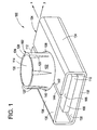
- the nut 102 is best illustrated in FIGURES 1 and 2.
- the nut 102 includes a rectangular plate 106 having a generally planar upper surface 108, a generally planar lower surface 109, and sidewalls 110 which connect the upper surface 108 to the lower surface 109.
- the nut 102 also includes a cylindrical member 112 which extends outwardly from the upper surface 108 of the nut 102.
- the cylindrical member 112 is preferably in the form of a right circular cylinder.
- An aperture 114 extends through the nut 102 from the plate 106 into the cylindrical member 112.
- the aperture 114 may be closed at the lower surface 109 of the plate 106 or it may, preferably, extend all the way through the plate 106.
- the aperture 114 defines an aperture wall 116 which is preferably threaded and is capable of receiving a fastener 118, such as a bolt or screw, to be attached thereto.
- the cylindrical member 112 also preferably includes a plurality of indents 120 provided along an outer surface 122 of the cylindrical member 112.
- the indents 120 extend from a top end 124 of the cylindrical member 112 generally straight down toward a bottom end 126 of the cylindrical member 112, which is provided at a position where the cylindrical member 112 extends from the upper surface 108 of the plate 106.
- the nut 102 may be formed by cold forming, stamping, or staking a nut member into a plate member. The nut 102 may then be heat treated, if desired, depending on the hardness of the material of the nut 102.
- the cage 104 is used for encaging the nut 102. Prior to encaging the nut 102, the cage 104 has generally planar upper and lower surfaces 128, 130.
- the cage 104 includes a base portion 132 and bendable first and second arm portions 134, 136 extending from opposite ends of the base portion 132.
- the first and second arm portions 134, 136 are preferably integrally formed with the base portion 132.
- An aperture 137 is provided through the base portion 132 of the cage 104 and the first and second arm portions 134, 136 have generally semi-circular cutouts 138, 140 at their free ends 142, 144.
- the nut 102 is positioned on the upper surface 128 of the base portion 132 such that the lower surface 109 of the nut 102 is placed flat on the upper surface 128 of the base portion 132.
- Each of the arm portions 134, 136 is then bent around one of the sidewalls 112 of the nut 102 and above the upper surface 108 of the nut 102.
- the free ends 142, 144 of the arm portions 134, 136 are typically spaced apart and the semi-circular cutouts 138, 140 are in alignment with one another.
- the cylindrical member 112 of the nut 102 extends through the semi-circular cutouts 138, 140.
- the cage 104 effectively encages the nut 102 to form the cage nut assembly 100, which is best illustrated in FIGURES 1 and 2.
- the cage 104 is sized so that the nut 102 has a limited range of movement in at least one dimension, and preferably in two dimensions, for example the "X" and "Y" axes as illustrated in FIGURE 1.
- a first portion (not shown) of a press (not shown) supports the lower surface 109 of the nut 102 off of the upper surface 128 of the base portion 132 of the cage 104, as the first portion of the press is capable of extending through the aperture 137 in the base portion 132 of the cage 104.
- a second portion (not shown) of the press then lowers onto the top end 124 of the cylindrical member 112 of the nut 102. The press then presses down onto the top end 124 of the cylindrical member 112 which results in the tearing of the cylindrical member 112 along the indents 120.
- flanges 146 are preferably formed by indents 120 in the cylindrical member 112, the flanges 146 could also be preformed in the cylindrical member 112 such that they are connected by a webbing (not shown) or any other similar or equivalent construction, which would tear upon the press pressing down on the top end 124 of the cylindrical member 112. Alternatively, the flanges 146 could be preformed in the cylindrical member 112 such that they are separated by slits (not shown), which would allow for the flanges 146 to be bent down upon the press pressing down on the top end 124 of the cylindrical member 112.
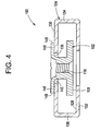
- the flanges 146 are folded down onto the lower surface 130 of the cage nut 104 at the arm portions 134, 136 and are bent at an angle so as to preferably allow only minimal contact with the lower surface 130 of the cage nut 104 at the arm portions 134, 136, as best illustrated in FIGURES 3 and 4.
- a diameter of the flanges 146 is sized to be large enough to ensure that the nut 102 cannot fall through the semi-circular cutouts 138, 140 of the cage 104, e.g., the diameter of the flanges 146 being larger than a diameter of the semi-circular cutouts 138, 140.
- the nut 102 is able to float in the "X" and "Y" axes and the lower surface 109 of the nut 102 does not contact the upper surface 128 of the base portion 132 of the cage 104.
- the lower surface 130 of the base portion 132 of the cage 104 is then welded to a workpiece 150.
- the workpiece 150 has an aperture 152 provided therethrough and first and second surfaces 154, 156.
- the lower surface 130 of the base portion 132 of the cage 104 is welded to the first surface 154 of the workpiece 150 such that the aperture 152 of the workpiece 150 is in communication with the aperture 137 through the base portion 132 of the cage 104, and with the aperture 114 which extends through the nut 102.
- the workpiece 150 and the cage 104 are then typically sent through an e-coat or ELPO bath that is meant to add a corrosion or paint coating to the first surface 154 of the workpiece 150.
- the folding over of the flanges 146 keeps the lower surface 109 of the nut 102 from coming into contact with the upper surface 128 of the base portion 132 of the cage 104, thus reducing the possibility that the cage 104 and the nut 102 will stick or adhere to each other after coating or welding is complete.
- the fastener 118 such as a bolt or screw, which has a head portion 160 and a threaded shank portion 162 extending therefrom, is then connected to the cage nut assembly 100 and the workpiece 150.
- the fastener 118 is connected by inserting the threaded shank portion 162 of the fastener 118 through the aperture 152 of the workpiece 150, through the aperture 137 of the base portion 132 of the cage 104 and into the aperture 114 of the nut 102, such that the threaded shank portion 162 of the fastener 118 is threadedly engaged with the threaded aperture wall 116 of the nut 102, until the head portion 160 of the fastener 118 abuts against the second surface 156 of the workpiece 150.
- the rectangular plate 106 of the nut 102 is pulled down to interface with the upper surface 128 of the base portion 132 of the cage 104, thus providing a solid joint between the nut 102, the cage 104, the workpiece 150 and the fastener 118.
- the rectangular plate 106 is able to be pulled down to interface with the upper surface 128 of the base portion 132 of the cage 104 because the flanges 146 are bent upward, as illustrated in FIGURES 5 and 6, as the fastener 118 is torqued into place.
- the cage nut assembly 200 includes a nut 202, a cage 204 and a bushing 270.
- the nut 202 is best illustrated in FIGURES 7 and 8.
- the nut 202 includes a rectangular plate 206 having a generally planar upper surface 208, a generally planar lower surface 209, and sidewalls 210 which connect the upper surface 208 to the lower surface.
- the nut 202 also includes a cylindrical member 212 which extends outwardly from the upper surface 208 of the nut 202.
- the cylindrical member 212 is preferably in the form of a right circular cylinder.
- An aperture 214 extends through the nut 202 from the plate 206 into the cylindrical member 212.
- the aperture 214 may be closed at the lower surface 209 of the plate 206 or it may, preferably, extend all the way through the plate 206.
- the aperture 214 defines an aperture wall 216 which is preferably threaded and is capable of receiving a fastener 218, such as a bolt or a screw, to be attached thereto.
- the cylindrical member 212 also preferably includes a plurality of indents 220 provided along an outer surface 222 of the cylindrical member 212.
- the indents 220 extend from a top end 224 of the cylindrical member 212 generally straight down toward a bottom end 226 of the cylindrical member 212, which is provided at a position where the cylindrical member 212 extends from the upper surface 208 of the plate 206.
- the nut 202 may be formed by cold forming, stamping, or staking a nut member into a plate member. The nut 202 may then be heat treated, if desired, depending on the hardness of the material of the nut 202.
- the cage 204 is used for encaging the nut 202. Prior to encaging the nut 202, the cage 204 has generally planar upper and lower surfaces 228, 230.
- the cage 204 includes a base portion 232 and bendable first and second arm portions 234, 236 extending from opposite ends of the base portion 232.
- the first and second arm portions 234, 236 are preferably integrally formed with the base portion 232.
- An aperture 237 is provided through the base portion 232 of the cage 204 and the first and second arm portions 234, 236 have generally semi-circular cutouts 238, 240 at their free ends 242, 244.
- the bushing 270 is a generally circular member having an aperture 272 provided therethrough defining an inner wall 274 and, thus, an inner diameter of the bushing 270.
- the bushing 270 also has an outer wall 276 which is defined by an upper flange 278 and a lower flange 280.
- the upper flange 278 extends radially outwardly from the inner wall 274 of the bushing 270 to the outer wall 276 of the bushing 270 and, thus, defines an outer diameter of the bushing 270 at the upper flange 278.
- the lower flange 280 extends radially outwardly from the inner wall 274 of the bushing 270 to the outer wall 276 of the bushing 270 and, thus, defines an outer diameter of the bushing 270 at the lower flange 280.
- the outer diameter of the bushing 270 at the lower flange 280 is preferably smaller than the outer diameter of the bushing 270 at the upper flange 280.
- the upper and lower flanges 278, 280 of the bushing 270 define a slot 282 therebetween such that the outer diameter of the bushing 270 at the slot 282 is less than the outer diameters of the bushing 270 at both the upper and lower flanges 278, 280.
- the bushing 270 is preferably formed of an electrically non-conductive material, such as plastic, and acts as an electro-plating inhibitor, as will be discussed further herein.
- the nut 202 is positioned on the upper surface 228 of the base portion 232 such that the lower surface 209 of the nut 202 is placed flat on the upper surface 228 of the base portion 232.
- the bushing 270 is positioned around the cylindrical member 212 of the nut 202 such that the cylindrical member 212 extends through the aperture 272 of the bushing 270.
- Each of the arm portions 234, 236 is bent around one of the sidewalls 212 of the nut 202 and above the upper surface 208 of the nut 202.
- the free ends 242, 244 of the arm portions 234, 236 are typically spaced apart and are positioned within the slot 282 of the bushing 270 such that the semi-circular cutouts 238, 240 are in alignment with one another.
- a diameter of the semi-circular cutouts 238, 240 is slightly larger than the outer diameter of the bushing 270 at the slot 282, but is smaller than the outer diameters of the bushing 270 at the upper and lower flanges 278, 280 such that the bushing 270 cannot fall into the cage 204 through the semi-circular cutouts 238, 240.
- the slot 282 is sized for an interference fit with the arm portions 234, 236 such that the upper flange 278 is substantially in abutment with the lower surface 230 of the cage 204 at the arm portions 234, 236, and such that the lower flange 280 is substantially in abutment with the upper surface 228 of the cage 204 at the arm portion 234, 236.
- the bushing 270 is secured to the cage 204 with the cylindrical member 212 of the nut 202 extending through the aperture 272 of the bushing 270.
- the inner diameter of the bushing 270 must be larger than an outer diameter of the cylindrical member 212 of the nut 202.
- the cage 204 effectively encages the nut 202 to form the cage nut assembly 200, which is best illustrated in FIGURES 7 and 8.
- the cage 204 is sized so that the nut 204 has a limited range of movement in at least one dimension, and preferably in two dimensions, for example the "X" and "Y" axes as illustrated in FIGURE 7.
- a first portion (not shown) of a press (not shown) supports the lower surface 209 of the nut 202 off of the upper surface 228 of the base portion 232 of the cage 204, as the first portion of the press is capable of extending through the aperture 237 in the base portion 232 of the cage 204.
- a second portion (not shown) of the press then lowers onto the top end 224 of the cylindrical member 212 of the nut 202. The press then presses down onto the top end 224 of the cylindrical member 212 which results in the tearing of the cylindrical member 212 along the indents 220.
- the tearing of the cylindrical member 212 along the indents 220 causes the nut 202 to collapse and provide a plurality of flanges 246.
- the flanges 246 are preferably formed by indents 220 in the cylindrical member 212, the flanges 246 could also be preformed in the cylindrical member 212 such that they are connected by a webbing (not shown) or any other similar or equivalent construction, which would tear upon the press pressing down on the top end 224 of the cylindrical member 212.
- the flanges 246 could be preformed in the cylindrical member 212 such that they are separated by slits (not shown), which would allow for the flanges 246 to be bent down upon the press pressing down on the top end 224 of the cylindrical member 212.
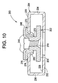
- the flanges 246 are folded down against the bushing 270 such that edges 248 of the flanges 246 do not come into contact with the arm portions 234, 236 of the cage nut 204, as best illustrated in FIGURES 9 and 10.
- a diameter of the flanges 246, measured from opposite edges 248 of the folded down flanges 246 (the edges 248 were previously the top end 224 of the cylindrical member 212), is sized to be large enough to ensure that the nut 202 cannot fall through the aperture 272 of the bushing 270, e.g., the diameter of the flanges 246 being larger than the inner diameter of the bushing 270.
- the nut 202 is able to float in the "X” and "Y" axes and the lower surface 209 of the nut 202 does not contact the upper surface 228 of the base portion 232 of the cage 204.
- the lower surface 230 of the base portion 232 of the cage 204 is then welded to a workpiece 250.
- the workpiece 250 has an aperture 252 provided therethrough and first and second surfaces 254, 256.
- the lower surface 230 of the base portion 232 of the cage 204 is welded to the first surface 254 of the workpiece 250 such that the aperture 252 of the workpiece 250 is in communication with the aperture 237 through the base portion 232 of the cage 204, and with the aperture 214 which extends through the nut 202.
- the workpiece 250 and the cage 204 are then typically sent through an e-coat or ELPO bath that is meant to add a corrosion or paint coating to the first surface 254 of the workpiece 250.
- the folding over of the flanges 246 keeps the lower surface 209 of the nut 202 from coming into contact with the upper surface 228 of the base portion 232 of the cage 204, thus reducing the possibility that the cage 204 and the nut 202 will stick or adhere to each other after coating or welding is complete.
- the bushing 270 acts as an electro-plating inhibitor. With the bushing 270 in place, there is no metal to metal contact between the nut 202 and the cage 204 such that when electricity moves through the cage 204 to deposit paint thereon, the nut 202 will not receive an electrical current and, thus, will not have paint deposited thereon. If the nut 202 and the cage 204 are in contact with one another, the nut 202 may have some paint deposited thereon which could cause problems with the nut 202 if the aperture wall 216 is finely threaded, as the paint or like will cause torqueing issues in the fine threads of the aperture wall 216. If the aperture wall 216 of the nut 202 is not finely threaded, but rather is coarsely threaded, the deposit of paint or the like on the threads of the aperture wall 216 is not as big a concern with regard to torqueing issues.
- the fastener 218 is connected by inserting the threaded shank portion 262 of the fastener 218 through the aperture 252 of the workpiece 250, through the aperture 237 of the base portion 232 of the cage 204 and into the aperture 214 of the nut 202, such that the threaded shank portion 262 of the fastener 218 is threadedly engaged with the threaded aperture wall 216 of the nut 202, until the head portion 260 of the fastener 218 abuts against the second surface 256 of the workpiece 250.
- the rectangular plate 206 of the nut 202 is pulled down to interface with the upper surface 228 of the base portion 232 of the cage 204, thus providing a solid joint between the nut 202, the cage 204, the bushing 270, the workpiece 250 and the fastener 218.
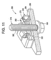
- the rectangular plate 206 is able to be pulled down to interface with the upper surface 228 of the base portion 232 of the cage 204 because the flanges 246 are bent upward, as illustrated in FIGURES 11 and 12, as the fastener 218 is torqued into place.
- the cage nut assembly 300 includes a nut 302 and a cage 304.
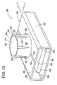
- the nut 302 is best illustrated in FIGURES 13 and 14.
- the nut 302 includes a rectangular plate 306 having a generally planar upper surface 308, a generally planar lower surface 309, and sidewalls 310 which connect the upper surface 308 to the lower surface 309.
- the nut 302 also includes a cylindrical member 312 which extends outwardly from the upper surface 308 of the nut 302.
- the cylindrical member 312 is preferably in the form of a right circular cylinder.
- An aperture 314 extends through the nut 302 from the plate 306 into the cylindrical member 312.
- the aperture 314 may be closed at the lower surface 309 of the plate 306 or it may, preferably, extend all the way through the plate 306.
- the aperture 314 defines an aperture wall 316 which is preferably threaded and is capable of receiving a fastener 318, such as a bolt or screw, to be attached thereto.
- the cylindrical member 312 also preferably includes a plurality of indents 320 provided along an outer surface 322 of the cylindrical member 312.
- the indents 320 extend from a top end 324 of the cylindrical member 312 generally straight down toward a bottom end 326 of the cylindrical member 312, which is provided at a position where the cylindrical member 312 extends from the upper surface 308 of the plate 306.
- the nut 302 may be formed by cold forming, stamping, or staking a nut member into a plate member. The nut 302 may then be heat treated, if desired, depending on the hardness of the material of the nut 302.
- the cage 304 is used for encaging the nut 302. Prior to encaging the nut 302, the cage 304 has generally planar upper and lower surfaces 328, 330.
- the cage 304 includes a base portion 332 and bendable first and second arm portions 334, 336 extending from opposite ends of the base portion 332.
- the first and second arm portions 334, 336 are preferably integrally formed with the base portion 332.
- An aperture 337 is provided through the base portion 332 of the cage 304 and the first and second arm portions 334, 336 have generally semi-circular cutouts 338, 340 at their free ends 342, 344.
- the nut 302 is positioned on the upper surface 328 of the base portion 332 such that the lower surface 309 of the nut 302 is placed flat on the upper surface 328 of the base portion 332.
- Each of the arm portions 334, 336 is then bent around one of the sidewalls 312 of the nut 302 and above the upper surface 308 of the nut 302.
- the free ends 342, 344 of the arm portions 334, 336 are typically spaced apart and the semi-circular cutouts 338, 340 are in alignment with one another.
- the cylindrical member 312 of the nut 302 extends through the semi-circular cutouts 338, 340.
- the cage 304 effectively encages the nut 302 to form the cage nut assembly 300, which is best illustrated in FIGURES 13 and 14.
- the cage 304 is sized so that the nut 302 has a limited range of movement in at least one dimension, and preferably in two dimensions, for example the "X" and "Y" axes as illustrated in FIGURE 13.
- a first portion (not shown) of a press (not shown) supports the lower surface 309 of the nut 302 off of the upper surface 328 of the base portion 332 of the cage 304, as the first portion of the press is capable of extending through the aperture 337 in the base portion 332 of the cage 304.
- a second portion (not shown) of the press then lowers onto the top end 324 of the cylindrical member 312 of the nut 302. The press then presses down onto the top end 324 of the cylindrical member 312 which results in the tearing of the cylindrical member 312 along the indents 320.
- flanges 346 are preferably formed by indents 320 in the cylindrical member 312, the flanges 346 could also be preformed in the cylindrical member 312 such that they are connected by a webbing (not shown) or any other similar or equivalent construction, which would tear upon the press pressing down on the top end 324 of the cylindrical member 312. Alternatively, the flanges 346 could be preformed in the cylindrical member 312 such that they are separated by slits (not shown), which would allow for the flanges 346 to be bent down upon the press pressing down on the top end 324 of the cylindrical member 312.
- the flanges 346 are curved or mushroomed such that only edges 348 of the flanges 346 contact the lower surface 330 of the cage nut 304 at the arm portions 334, 336.
- the nut 302 has only minimal contact with the lower surface 330 of the cage 304 at the arm portions 334, 336, as best illustrated in FIGURES 15 and 16.
- a diameter of the flanges 346 is sized to be large enough to ensure that the nut 302 cannot fall through the semi-circular cutouts 338, 340 of the cage 304, e.g., the diameter of the flanges 346 being larger than a diameter of the semi-circular cutouts 338, 340.
- the nut 302 is able to float in the "X" and "Y" axes and the lower surface 309 of the nut 302 does not contact the upper surface 328 of the base portion 332 of the cage 304.
- the lower surface 330 of the base portion 332 of the cage 304 is then welded to a workpiece 350.
- the workpiece 350 has an aperture 352 provided therethrough and first and second surfaces 354, 356.
- the lower surface 330 of the base portion 332 of the cage 304 is welded to the first surface 354 of the workpiece 350 such that the aperture 352 of the workpiece 350 is in communication with the aperture 337 through the base portion 332 of the cage 304, and with the aperture 314 which extends through the nut 302.
- the workpiece 350 and the cage 304 are then typically sent through an e-coat or ELPO bath that is meant to add a corrosion or paint coating to the first surface 354 of the workpiece 350.
- the curving/mushrooming of the flanges 346 keeps the lower surface 309 of the nut 302 from coming into contact with the upper surface 328 of the base portion 332 of the cage 304, thus reducing the possibility that the cage 304 and the nut 302 will stick or adhere to each other after coating or welding is complete.
- the fastener 318 such as a bolt or screw, which has a head portion 360 and a threaded shank portion 362 extending therefrom, is then connected to the cage nut assembly 300 and the workpiece 350.
- the fastener 318 is connected by inserting the threaded shank portion 362 of the fastener 318 through the aperture 352 of the workpiece 350, through the aperture 337 of the base portion 332 of the cage 304 and into the aperture 314 of the nut 302, such that the threaded shank portion 362 of the fastener 318 is threadedly engaged with the threaded aperture wall 316 of the nut 302, until the head portion 360 of the fastener 318 abuts against the second surface 356 of the workpiece 350.
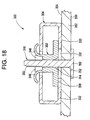
- the rectangular plate 306 of the nut 302 is pulled down to interface with the upper surface 328 of the base portion 332 of the cage 304, thus providing a solid joint between the nut 302, the cage 304, the workpiece 350 and the fastener 318.
- the rectangular plate 306 is able to be pulled down to interface with the upper surface 328 of the base portion 332 of the cage 304 because the flanges 346 are bent upward, as illustrated in FIGURES 17 and 18, as the fastener 318 is torqued into place.
- the cage nut assembly 400 includes a nut 402, a cage 404 and a bushing 470.
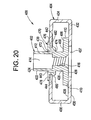
- the nut 402 is best illustrated in FIGURES 19 and 20.
- the nut 402 includes a rectangular plate 406 having a generally planar upper surface 408, a generally planar lower surface 409, and sidewalls 410 which connect the upper surface 408 to the lower surface.
- the nut 402 also includes a cylindrical member 412 which extends outwardly from the upper surface 408 of the nut 402.
- the cylindrical member 412 is preferably in the form of a right circular cylinder.
- An aperture 414 extends through the nut 402 from the plate 406 into the cylindrical member 412.
- the aperture 414 may be closed at the lower surface 409 of the plate 406 or it may, preferably, extend all the way through the plate 406.
- the aperture 414 defines an aperture wall 416 which is preferably threaded and is capable of receiving a fastener 418, such as a bolt or a screw, to be attached thereto.
- the cylindrical member 412 also preferably includes a plurality of indents 420 provided along an outer surface 422 of the cylindrical member 412.
- the indents 420 extend from a top end 424 of the cylindrical member 412 generally straight down toward a bottom end 426 of the cylindrical member 412, which is provided at a position where the cylindrical member 412 extends from the upper surface 408 of the plate 406.
- the nut 402 may be formed by cold forming, stamping, or staking a nut member into a plate member. The nut 402 may then be heat treated, if desired, depending on the hardness of the material of the nut 402.
- the cage 404 is used for encaging the nut 402. Prior to encaging the nut 402, the cage 404 has generally planar upper and lower surfaces 428, 430.
- the cage 404 includes a base portion 432 and bendable first and second arm portions 434, 436 extending from opposite ends of the base portion 432.
- the first and second arm portions 434, 436 are preferably integrally formed with the base portion 432.
- An aperture 437 is provided through the base portion 432 of the cage 404 and the first and second arm portions 434, 436 have generally semi-circular cutouts 438, 440 at their free ends 442, 444.
- the bushing 470 is a generally circular member having an aperture 472 provided therethrough defining an inner wall 474 and, thus, an inner diameter of the bushing 470.
- the bushing 470 also has an outer wall 476 which is defined by an upper flange 478 and a lower flange 480.
- the upper flange 478 extends radially outwardly from the inner wall 474 of the bushing 470 to the outer wall 476 of the bushing 470 and, thus, defines an outer diameter of the bushing 470 at the upper flange 478.
- the lower flange 480 extends radially outwardly from the inner wall 474 of the bushing 470 to the outer wall 476 of the bushing 470 and, thus, defines an outer diameter of the bushing 470 at the lower flange 480.
- the outer diameter of the bushing 470 at the lower flange 480 is preferably smaller than the outer diameter of the bushing 470 at the upper flange 480.
- the upper and lower flanges 478, 480 of the bushing 470 define a slot 482 therebetween such that the outer diameter of the bushing 470 at the slot 482 is less than the outer diameters of the bushing 470 at both the upper and lower flanges 478, 480.
- the bushing 470 is preferably formed of an electrically non-conductive material, such as plastic, and acts as an electro-plating inhibitor, as will be discussed further herein.
- the nut 402 is positioned on the upper surface 428 of the base portion 432 such that the lower surface 409 of the nut 402 is placed flat on the upper surface 428 of the base portion 432.
- the bushing 470 is positioned around the cylindrical member 412 of the nut 402 such that the cylindrical member 412 extends through the aperture 472 of the bushing 470.
- Each of the arm portions 434, 436 is bent around one of the sidewalls 412 of the nut 402 and above the upper surface 408 of the nut 402.
- the free ends 442, 444 of the arm portions 434, 436 are typically spaced apart and are positioned within the slot 482 of the bushing 470 such that the semi-circular cutouts 438, 440 are in alignment with one another.
- a diameter of the semi-circular cutouts 438, 440 is slightly larger than the outer diameter of the bushing 470 at the slot 482, but is smaller than the outer diameters of the bushing 470 at the upper and lower flanges 478, 480 such that the bushing 470 cannot fall into the cage 404 through the semi-circular cutouts 438, 440.
- the slot 482 is sized for an interference fit with the arm portions 434, 436 such that the upper flange 478 is substantially in abutment with the lower surface 230 of the cage 404 at the arm portions 434, 436, and such that the lower flange 480 is substantially in abutment with the upper surface 428 of the cage 404 at the arm portion 434, 436.
- the bushing 470 is secured to the cage 404 with the cylindrical member 412 of the nut 402 extending through the aperture 472 of the bushing 470.
- the inner diameter of the bushing 470 must be larger than an outer diameter of the cylindrical member 412 of the nut 402.
- the cage 404 effectively encages the nut 402 to form the cage nut assembly 400, which is best illustrated in FIGURES 19 and 20.
- the cage 404 is sized so that the nut 404 has a limited range of movement in at least one dimension, and preferably in two dimensions, for example the "X" and "Y" axes as illustrated in FIGURE 19.
- a first portion (not shown) of a press (not shown) supports the lower surface 409 of the nut 402 off of the upper surface 428 of the base portion 432 of the cage 404, as the first portion of the press is capable of extending through the aperture 437 in the base portion 432 of the cage 404.
- a second portion (not shown) of the press then lowers onto the top end 424 of the cylindrical member 412 of the nut 402. The press then presses down onto the top end 424 of the cylindrical member 412 which results in the tearing of the cylindrical member 412 along the indents 420.
- the tearing of the cylindrical member 412 along the indents 420 causes the nut 502 to collapse and provide a plurality of flanges 446.
- the flanges 446 are preferably formed by indents 420 in the cylindrical member 412
- the flanges 446 could also be preformed in the cylindrical member 412 such that they are connected by a webbing (not shown) or any other similar or equivalent construction, which would tear upon the press pressing down on the top end 424 of the cylindrical member 412.
- the flanges 446 could be preformed in the cylindrical member 412 such that they are separated by slits (not shown), which would allow for the flanges 446 to be bent down upon the press pressing down on the top end 424 of the cylindrical member 412.
- the flanges 446 are curved or mushroomed around the bushing 470 such that edges 448 of the flanges 446 do not contact the arm portions 434, 436 of the cage nut 404, as best illustrated in FIGURES 21 and 22. It should be noted that because the flanges 446 are curved/mushroomed around the bushing 470, instead of folded down onto the bushing 470, similar to the flanges 246 of the second embodiment described hereinabove, the upper flange 478 of the bushing 470 must provide for a larger outer diameter of the bushing 470 than does the upper flange 278 of the bushing 270 in order to ensure that the ends 448 of the flanges 446 do not contact the lower surface 430 of the cage nut 404 at the arm portions 434, 436.
- a diameter of the flanges 446 measured from opposite edges 448 of the curved/mushroomed flanges 446 (the edges 448 were previously the top end 424 of the cylindrical member 412), is sized to be large enough to ensure that the nut 402 cannot fall through the aperture 472 of the bushing 470, e.g., the diameter of the flanges 446 being larger than the inner diameter of the bushing 470.
- the nut 402 is able to float in the "X” and "Y" axes and the lower surface 409 of the nut 402 does not contact the upper surface 428 of the base portion 432 of the cage 404.
- the lower surface 430 of the base portion 432 of the cage 404 is then welded to a workpiece 450.
- the workpiece 450 has an aperture 452 provided therethrough and first and second surfaces 454, 456.
- the lower surface 430 of the base portion 432 of the cage 404 is welded to the first surface 454 of the workpiece 450 such that the aperture 452 of the workpiece 450 is in communication with the aperture 437 through the base portion 432 of the cage 404, and with the aperture 414 which extends through the nut 402.
- the workpiece 450 and the cage 404 are then typically sent through an e-coat or ELPO bath that is meant to add a corrosion or paint coating to the first surface 454 of the workpiece 450.
- the curving/mushrooming of the flanges 446 keeps the lower surface 409 of the nut 402 from coming into contact with the upper surface 428 of the base portion 432 of the cage 404, thus reducing the possibility that the cage 404 and the nut 402 will stick or adhere to each other after coating or welding is complete.
- the bushing 470 acts as an electro-plating inhibitor. With the bushing 470 in place, there is no metal to metal contact between the nut 402 and the cage 404 such that when electricity moves through the cage 404 to deposit paint thereon, the nut 402 will not receive an electrical current and, thus, will not have paint deposited thereon. If the nut 402 and the cage 404 are in contact with one another, the nut 402 may have some paint deposited thereon which could cause problems with the nut 402 if the aperture wall 416 is finely threaded, as the paint or like will cause torqueing issues in the fine threads of the aperture wall 416. If the aperture wall 416 of the nut 402 is not finely threaded, but rather is coarsely threaded, the deposit of paint or the like on the threads of the aperture wall 416 is not as big a concern with regard to torqueing issues.
- the fastener 418 such as a bolt or screw, which has a head portion 460 and a threaded shank portion 462 extending therefrom, is then connected to the cage nut assembly 400 and the workpiece 450.
- the fastener 418 is connected by inserting the threaded shank portion 462 of the fastener 418 through the aperture 452 of the workpiece 450, through the aperture 437 of the base portion 432 of the cage 404 and into the aperture 414 of the nut 402, such that the threaded shank portion 462 of the fastener 418 is threadedly engaged with the threaded aperture wall 416 of the nut 402, until the head portion 460 of the fastener 418 abuts against the second surface 456 of the workpiece 450.
- the rectangular plate 406 of the nut 402 is pulled down to interface with the upper surface 428 of the base portion 432 of the cage 404, thus providing a solid joint between the nut 402, the cage 404, the bushing 470, the workpiece 450 and the fastener 418.
- the rectangular plate 406 is able to be pulled down to interface with the upper surface 428 of the base portion 432 of the cage 404 because the flanges 446 are bent upward, as illustrated in FIGURES 23 and 24, as the fastener 418 is torqued into place.
- the cage nut assembly 500 includes a nut 502 and a cage 504.
- the nut 502 is identical to the nuts 102, 202, 302, 402 of the first, second, third and fourth embodiments and, thus, will not be described in detail herein again with the understanding that like reference numerals refer to like parts.
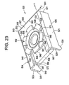
- the cage 504 is used for encaging the nut 502. Prior to encaging the nut 502, the cage 504 is formed to have a first side wall 521, a second side wall 523, a rear wall 525 and a top wall 527, all of which are integrally formed, as best illustrated in FIGURES 25 and 26.
- the first side wall 521 extends along the "X" axis and has a first side edge 529, a second side edge 531, a top edge 533 and a bottom edge 535. Proximate to the first side edge 529, a tab 539 extends downwardly from the bottom edge 535, away from the top edge 533.
- the second side wall 523 extends along the "X" axis and is parallel to the first side wall 521.
- the second side wall 523 has a first side edge 541, a second side edge 543, a top edge 545 and a bottom edge 547. Proximate to the first side edge 541, a tab 549 extends downwardly from the bottom edge 547, away from the top edge 545.
- the rear wall 525 extends along the "Y" axis between the first and second side walls 521, 523, proximate to the second side edges 531, 543 thereof, respectively.
- the rear wall 525 has a first side edge 551, a second side edge 553, a top edge 555 and a bottom edge 557.
- the first side edge 551 is positioned proximate to the second side edge 531 of the first side wall 521 and the second side edge 553 is positioned proximate to the second side edge 543 of the second side wall 523.
- Equidistant from the first side edge 551 and the second side edge 553, a tab 559 extends downwardly from the bottom edge 557, away from the top edge 555.
- the top wall 527 has a first edge 561, a second edge 563, a third edge 565 and a fourth edge 567.
- the top wall 527 connects the first and second side walls 521, 523 and the rear wall 525 together.
- the first edge 561 of the top wall 527 being connected to the top edge 533 of the first side wall 521
- the second edge 563 of the top wall 527 being connected to the top edge 555 of the rear wall 525
- the third edge 565 of the top wall 527 being connected to the top edge 545 of the second side wall 523.
- the top wall 527 includes a cavity 569 which has its opening at the fourth edge 567 of the top wall 527, and which extends toward the second edge 563 of the top wall 527, but does not extend to the second edge 563 of the top wall 527.
- a base portion 571 of the cavity 569, which is proximate to the second edge 563 of the top wall 527, is generally circular whereas a top portion 573 of the cavity 569, which is provided proximate to the fourth edge 567 of the top wall 527, is generally rectangular.
- the nut 502 is positioned within the cage 504 by moving the cylindrical member 512 into the cavity 569 and positioning the cylindrical member 512 into the base portion 571 of the cavity 569.
- a first portion (not shown) of a press (not shown) supports the lower surface (not shown) of the nut 502 as the first portion of the press is capable of extending into the cage 504 as the cage 504 has no bottom wall.
- a second portion (not shown) of the press then lowers onto the top end 524 of the cylindrical member 512 of the nut 502. The press then presses down onto the top end 524 of the cylindrical member 512 which results in the tearing of the cylindrical member 512 along the indents (not shown).
- the tearing of the cylindrical member 512 along the indents 520 causes the nut 502 to collapse and provide a plurality of flanges 546.
- the flanges 546 are preferably formed by indents 520 in the cylindrical member 512, the flanges 546 could also be preformed in the cylindrical member 512 such that they are connected by a webbing (not shown) or any other similar or equivalent construction, which would tear upon the press pressing down on the top end 524 of the cylindrical member 512.
- the flanges 546 could be preformed in the cylindrical member 512 such that they are separated by slits (not shown), which would allow for the flanges 546 to be bent down upon the press pressing down on the top end 524 of the cylindrical member 512.
- the flanges 546 are folded down onto the top wall 527 of the cage 504 and are bent at an angle so as to preferably allow only minimal contact with the top wall 527 of the cage 504, as best illustrated in FIGURES 25 and 26.
- a diameter of the flanges 546, measured from opposite edges 548 of the folded flanges 546 (the edges 548 of the flanges 546 were previously the top end 524 of the cylindrical member 512), is sized to be large enough to ensure that the nut 502 cannot fall through the cavity 569 of the cage 504, e.g., the diameter of the flanges 546 being larger than a diameter of the base portion 571 of the cavity 569.
- the nut 502 is able to float in the "X” and “Y” axes.
- the cage 504 is sized so that the plate 506 of the nut 502 does not extend beyond the bottom edges 535, 547, 557 of the first and second side walls 521, 523 and the rear wall 525.
- the tabs 539, 549, 559 of the cage 504 are then welded to a workpiece 550.
- the workpiece 550 has an aperture 552 provided therethrough and first and second surfaces 554, 556.
- the tabs 539, 549, 559 of the cage 504 are welded to the first surface 554 of the workpiece 550 such that the aperture 552 of the workpiece 550 is in communication with the aperture 514 which extends through the nut 502.
- the workpiece 550 and the cage 504 are then typically sent through an e-coat or ELPO bath that is meant to add a corrosion or paint coating to the first surface 554 of the workpiece 550.
- the folding over of the flanges 546 keeps the lower surface 509 of the nut 502, which is positioned above the bottom edges 535, 547, 557 of the cage 504, from coming into contact with the first surface 554 of the workpiece 550, thus reducing the possibility that the workpiece 550 and the nut 502 will stick or adhere to each other after coating or welding is complete.
- the fastener 518 such as a bolt or screw, which has a head portion 560 and a threaded shank portion 562 extending therefrom, is then connected to the cage nut assembly 500 and the workpiece 550.
- the fastener 518 is connected by inserting the threaded shank portion 562 of the fastener 518 through the aperture 552 of the workpiece 550 and into the aperture 514 of the nut 502, such that the threaded shank portion 562 of the fastener 518 is threadedly engaged with the threaded aperture wall 516 of the nut 502, until the head portion 560 of the fastener 518 abuts against the second surface 556 of the workpiece 550.
- the rectangular plate 506 of the nut 502 is pulled down to interface the first surface 554 of the workpiece 550, thus providing a solid joint between the nut 502, the cage 504, the workpiece 550 and the fastener 518.
- the rectangular plate 506 is able to be pulled down to interface the first surface 554 of the workpiece 550 because the flanges 546 are bent upward, as illustrated in FIGURES 27 and 28, as the fastener 518 is torqued into place.
- the cage nut assemblies 100, 300, 500 are preferably used when the nut 100, 300, 500 of the cage nut assemblies 100, 300, 500 has an aperture wall 116, 316, 516 which is not finely threaded, but rather is coarsely threaded, as costs are saved when the bushing 170, 370, 570 is not included in the cage nut assembly 100, 300, 500.
- the cage nut assemblies 200, 400 are preferably used when the nut 200, 400 of the cage nut assemblies 200, 400 has an aperture wall 216, 416 which is finely threaded.
- the cage nut assemblies 100, 300, 500 can also be used when the aperture wall 116, 316, 516 is finely threaded and the cage nut assemblies 200, 400 can also be used when the aperture wall 216, 416 is not finely threaded, but rather is coarsely threaded.
- the cage nut assembly 500 could be configured to have a bushing, similar to the cage nut assembly 200 of the second embodiment described hereinabove. It should further be noted that, if desired, the cage nut assembly 500 could be configured by curving/mushrooming the flanges 546, similar to the cage nut assembly 300 of the third embodiment described hereinabove. It should further be noted that, if desired, the cage nut assembly 500 could be configured by curving/mushrooming the flanges 546 and to have a bushing, similar to the cage nut assembly 400 of the fourth embodiment described hereinabove.
Landscapes
- Engineering & Computer Science (AREA)
- General Engineering & Computer Science (AREA)
- Mechanical Engineering (AREA)
- Coating With Molten Metal (AREA)
- Connection Of Plates (AREA)
- Mutual Connection Of Rods And Tubes (AREA)
- Types And Forms Of Lifts (AREA)
Description
- This patent application claims the benefit of domestic priority of United States Patent Application Serial No. 10/341,575, filed January 13, 2003, and entitled "Collapsible Nut".
- The present invention relates to a cage nut assembly, a nut used in the cage nut assembly, and a method of forming the cage nut assembly.
- Cage nut assemblies are well known in the art and provide a useful function in that they are able to hold a threaded nut at locations in a frame that are difficult or in some cases impossible to reach with a tool. Cage nut assemblies are used in vehicles for seat attachments, radiator attachments, chassis to drive train attachments, and for any other nut application that requires the nut to have an "X" and "Y" axis adjustability to accommodate tolerance variations and enable engagement thereof by a male threaded fastener.
- Problems have arisen in conjunction with prior art cage nut assemblies. One problem occurs after the cages of the cage nut assemblies are welded to a mating surface, such as an automobile frame. After the cages are welded to the automobile frame, the frames are sent through an e-coat or ELPO bath that adds a corrosion or paint coating thereto. In cage nut assemblies where the underside of the nut is capable of sitting flat on the cage, the nut and cage may stick together when the e-coat or ELPO bath is applied thereto, thus removing the intended float/adjustability of the nut within the cage.
- At least two known and separate United States patents have acknowledged this problem and have attempted to provide cage nut assemblies which solve the problem. United States Patent No. 5,096,350 discusses the use of any item attached to either the cage or the nut, or to a third part positioned between the nut and the cage, that flattens out when the nut is torqued into place. This item allows for the stand-off needed during the e-coat and provides for a solid joint when the nut is torqued into place. These flattenable projections either on the cage or the nut, or the addition of a third part with the flattenable projections thereon, provide high manufacturing costs to the cage nut assembly.
- United States Patent No. 5,630,686 discusses the use of plastic rings staked at the top of a nut extrusion that hold the nut up off of the cage floor or mating panel, thus removing the possibility that the e-coat will allow the parts to stick together. The plastic rings are flexible enough to allow a solid joint to take place when the nut is lowered to interface with the cage floor or mating panel when the nut is torqued down. This patent requires the plastic rings in order to perform the desired function. The addition of the plastic rings to the cage nut assembly is expensive and the rings sometimes disengage from the assembly when the nut is torqued into place thus causing a buzz, squeak rattle ("BSR") issue with customers.
- Thus, there is a need for a cage nut assembly which does not allow the nut to become stuck to the cage during the application of an e-coat or ELPO bath and which overcomes the disadvantages of the aforementioned United States patents which have attempted to solve this same problem.
- A primary object of an embodiment of the present invention is to provide a cage nut assembly which reduces the possibility of the nut sticking to the cage when an e-coat or ELPO bath is applied thereto.
- Another object of an embodiment of the present invention is to provide a cage nut assembly that has strong joints between the nuts and the cages after the nuts are torqued into place.
- Another object of an embodiment of the present invention is to provide a cage nut assembly where the nut is allowed to float within the cage after coating of the mating surface, to which the cage is attached.
- Still another object of an embodiment of the present invention is to provide a cage nut assembly which can be economically manufactured.
- Another object of an embodiment of the present invention is to provide a cage nut assembly which has a nut that can be collapsed in order to suspend the nut from the cage.
- Yet another object of an embodiment of the present invention is to provide a cage nut assembly in which the nut is suspended from the cage prior to the torqueing of a fastener into place, and thereafter, the nut being able to interface with the cage when the fastener is torqued into place to provide a solid joint.
- Briefly, and in accordance with the foregoing, an embodiment of the present invention provides a cage nut assembly as recited in Claim 1. The present invention also provides a method securing a nut member to a cage member as recited in Claim 15. The nut has a cylindrical portion extending from a plate portion. The nut is encaged in the cage such that the cylindrical portion extends through an aperture in the cage. The cylindrical portion of the nut is collapsible such that when a press presses down on the cylindrical portion, the nut collapses and provides a plurality of flanges. The flanges are folded down or curved/mushroomed such that the plate portion of the nut is suspended within the cage such that the nut will not stick to the cage or workpiece when they are coated with e-coat or ELPO. Upon torqueing a fastener into place, the plate portion interfaces with the cage or workpiece to provide a solid joint, with the flanges being bent up to allow for the lowering of the plate portion to the cage or workpiece. A bushing can also be provided on the cage around the cylindrical portion to act as an electro-plating inhibitor such that the nut and the cage do not come into contact with one another.
- FIGURES 1-6 illustrate a cage nut assembly which is in accordance with a first embodiment of the present invention where the flanges are folded down and a bushing is not provided. FIGURES 7-12 illustrate a cage nut assembly which is in accordance with a second embodiment of the present invention where the flanges are folded down and a bushing is provided. FIGURES 13-18 illustrate a cage nut assembly which is in accordance with a third embodiment of the present invention where the flanges are curved/mushroomed and a bushing is not provided. FIGURES 19-24 illustrate a cage nut assembly which is in accordance with a fourth embodiment of the present invention where the flanges are curved/mushroomed and a bushing is provided. FIGURES 25-28 illustrate a cage nut assembly which is in accordance with a fifth embodiment of the present invention where the flanges are folded down and a bushing is not provided, and which has a cage which is different in structure than those illustrated in FIGURES 1-24.
- The features of the present invention which are believed to be novel are described in detail hereinbelow. The organization and manner of the structure and operation of the invention, together with further objects and advantages thereof, may best be understood by reference to the following description taken in connection with the accompanying drawings wherein like reference numerals identify like elements in which:
- FIGURE 1 is a perspective view of a cage nut assembly which is in accordance with a first embodiment of the invention;
- FIGURE 2 is a cross-sectional view of the cage nut assembly shown in FIGURE 1;
- FIGURE 3 is a perspective view of the cage nut assembly shown in FIGURE 1, showing the flanges of the nut being folded down onto a cage;
- FIGURE 4 is a cross-sectional view of the cage nut assembly shown in FIGURE 3;
- FIGURE 5 is a perspective view of the cage nut assembly of FIGURES 1-4, showing the assembly being connected to a workpiece by a fastener;
- FIGURE 6 is a cross-sectional view of the cage nut assembly shown in FIGURE 5, showing the assembly being connected to a workpiece by a fastener;
- FIGURE 7 is a perspective view of a cage nut assembly which is in accordance with a second embodiment of the invention;
- FIGURE 8 is a cross-sectional view of the cage nut assembly shown in FIGURE 7;
- FIGURE 9 is a perspective view of the cage nut assembly shown in FIGURE 7, showing the flanges of the nut being folded down onto a bushing connected to a cage;
- FIGURE 10 is a cross-sectional view of the cage nut assembly shown in FIGURE 9;
- FIGURE 11 is a perspective view of the cage nut assembly of FIGURES 7-10, showing the assembly being connected to a workpiece by a fastener;
- FIGURE 12 is a cross-sectional view of the cage nut assembly shown in FIGURE 11, showing the assembly being connected to a workpiece by a fastener;
- FIGURE 13 is a perspective view of a cage nut assembly which is in accordance with a third embodiment of the invention;
- FIGURE 14 is a cross-sectional view of the cage nut assembly shown in FIGURE 13;
- FIGURE 15 is a perspective view of the cage nut assembly shown in FIGURE 13, showing the flanges of the nut being curved/mushroomed down onto a cage;
- FIGURE 16 is a cross-sectional view of the cage nut assembly shown in FIGURE 15;
- FIGURE 17 is a perspective view of the cage nut assembly of FIGURES 13-16, showing the assembly being connected to a workpiece by a fastener;
- FIGURE 18 is a cross-sectional view of the cage nut assembly shown in FIGURE 17, showing the assembly being connected to a workpiece by a fastener;
- FIGURE 19 is a perspective view of a cage nut assembly which is in accordance with a fourth embodiment of the invention;
- FIGURE 20 is a cross-sectional view of the cage nut assembly shown in FIGURE 19;
- FIGURE 21 is a perspective view of the cage nut assembly shown in FIGURE 19, showing the flanges of the nut being curved/mushroomed down onto a bushing connected to a cage;
- FIGURE 22 is a cross-sectional view of the cage nut assembly shown in FIGURE 21;
- FIGURE 23 is a perspective view of the cage nut assembly of FIGURES 19-22, showing the assembly being connected to a workpiece by a fastener;
- FIGURE 24 is a cross-sectional view of the cage nut assembly shown in FIGURE 23, showing the assembly being connected to a workpiece by a fastener;
- FIGURE 25 is a perspective view of the cage nut assembly which is in accordance with a fifth embodiment of the invention, showing the flanges of the nut being folded down onto a cage;
- FIGURE 26 is a cross-sectional view of the cage nut assembly shown in FIGURE 25;
- FIGURE 27 is a perspective view of the cage nut assembly of FIGURES 25-26, showing the assembly being connected to a workpiece by a fastener; and
- FIGURE 28 is a cross-sectional view of the cage nut assembly shown in FIGURE 27, showing the assembly being connected to a workpiece by a fastener.
- While this invention may be susceptible to embodiment in different forms, there is shown in the drawings and will be described herein in detail, specific embodiments with the understanding that the present disclosure is to be considered an exemplification of the principles of the invention, and is not intended to limit the invention to that as illustrated and described herein.
- Several different embodiments of the present invention are shown and described herein. Specifically, a
cage nut assembly 100 which is in accordance with a first embodiment of the present invention is shown in FIGURES 1-6. Acage nut assembly 200 which is in accordance with a second embodiment of the present invention is shown in FIGURES 7-12. Acage nut assembly 300 which is in accordance with a third embodiment of the present invention is shown in FIGURES 13-18. Acage nut assembly 400 which is in accordance with a fourth embodiment of the present invention is shown in FIGURES 19-24. Acage nut assembly 500 which is in accordance with a fifth embodiment of the present invention is shown in FIGURES 25-28. Like elements are denoted with like reference numerals with the first embodiment being illustrated and described using reference numerals in the one hundreds, the second embodiment being illustrated and described using reference numerals in the two hundreds, the third embodiment being illustrated and described using reference numerals in the three hundreds, the fourth embodiment being illustrated and described using reference numerals in the four hundreds, and the fifth embodiment being illustrated and described using reference numerals in the five hundreds. - Each one of the cage nut assemblies shown in the FIGURES and described herein provides a cage nut assembly which generally includes a cage and a nut that is capable of collapsing to provide a plurality of flanges which can then be folded down or curved/mushroomed such that a plate portion of the nut is suspended within the cage to prevent the nut from sticking to the cage or a workpiece when they are coated with e-coat or ELPO. Thus, each one of the cage nut assemblies (1) reduces the possibility of the nut sticking to the cage when an e-coat or ELPO bath is applied thereto; (2) has strong joints between the nuts and the cages after the nuts are torqued into place; (3) allows the nut to float within the cage after coating of the mating surface to which the cage is attached; (4) can be economically manufactured; and (5) has a nut that can be collapsed in order to suspend the nut from the cage.
- Attention is directed to a
cage nut assembly 100 which is in accordance with a first embodiment of the present invention, and which is best illustrated in FIGURES 1-6. Thecage nut assembly 100 includes anut 102 and acage 104. - The
nut 102 is best illustrated in FIGURES 1 and 2. Thenut 102 includes arectangular plate 106 having a generally planarupper surface 108, a generally planarlower surface 109, and sidewalls 110 which connect theupper surface 108 to thelower surface 109. Thenut 102 also includes acylindrical member 112 which extends outwardly from theupper surface 108 of thenut 102. Thecylindrical member 112 is preferably in the form of a right circular cylinder. Anaperture 114 extends through thenut 102 from theplate 106 into thecylindrical member 112. Theaperture 114 may be closed at thelower surface 109 of theplate 106 or it may, preferably, extend all the way through theplate 106. Theaperture 114 defines anaperture wall 116 which is preferably threaded and is capable of receiving afastener 118, such as a bolt or screw, to be attached thereto. - The
cylindrical member 112 also preferably includes a plurality ofindents 120 provided along anouter surface 122 of thecylindrical member 112. Theindents 120 extend from atop end 124 of thecylindrical member 112 generally straight down toward abottom end 126 of thecylindrical member 112, which is provided at a position where thecylindrical member 112 extends from theupper surface 108 of theplate 106. - The
nut 102 may be formed by cold forming, stamping, or staking a nut member into a plate member. Thenut 102 may then be heat treated, if desired, depending on the hardness of the material of thenut 102. - The
cage 104 is used for encaging thenut 102. Prior to encaging thenut 102, thecage 104 has generally planar upper andlower surfaces cage 104 includes abase portion 132 and bendable first andsecond arm portions base portion 132. The first andsecond arm portions base portion 132. - An
aperture 137 is provided through thebase portion 132 of thecage 104 and the first andsecond arm portions semi-circular cutouts free ends - In operation, and as best illustrated in FIGURES 1-6, the
nut 102 is positioned on theupper surface 128 of thebase portion 132 such that thelower surface 109 of thenut 102 is placed flat on theupper surface 128 of thebase portion 132. - Each of the
arm portions sidewalls 112 of thenut 102 and above theupper surface 108 of thenut 102. The free ends 142, 144 of thearm portions semi-circular cutouts cylindrical member 112 of thenut 102 extends through thesemi-circular cutouts cage 104 effectively encages thenut 102 to form thecage nut assembly 100, which is best illustrated in FIGURES 1 and 2. Thecage 104 is sized so that thenut 102 has a limited range of movement in at least one dimension, and preferably in two dimensions, for example the "X" and "Y" axes as illustrated in FIGURE 1. - Once the
cage nut assembly 100 is formed, a first portion (not shown) of a press (not shown) supports thelower surface 109 of thenut 102 off of theupper surface 128 of thebase portion 132 of thecage 104, as the first portion of the press is capable of extending through theaperture 137 in thebase portion 132 of thecage 104. A second portion (not shown) of the press then lowers onto thetop end 124 of thecylindrical member 112 of thenut 102. The press then presses down onto thetop end 124 of thecylindrical member 112 which results in the tearing of thecylindrical member 112 along theindents 120. - The tearing of the
cylindrical member 112 along theindents 120 causes thenut 102 to collapse and provide a plurality offlanges 146. It should be noted that while theflanges 146 are preferably formed byindents 120 in thecylindrical member 112, theflanges 146 could also be preformed in thecylindrical member 112 such that they are connected by a webbing (not shown) or any other similar or equivalent construction, which would tear upon the press pressing down on thetop end 124 of thecylindrical member 112. Alternatively, theflanges 146 could be preformed in thecylindrical member 112 such that they are separated by slits (not shown), which would allow for theflanges 146 to be bent down upon the press pressing down on thetop end 124 of thecylindrical member 112. - The
flanges 146 are folded down onto thelower surface 130 of thecage nut 104 at thearm portions lower surface 130 of thecage nut 104 at thearm portions flanges 146, measured fromopposite edges 148 of the folded flanges 146 (theedges 148 of theflanges 146 were previously thetop end 124 of the cylindrical member 112), is sized to be large enough to ensure that thenut 102 cannot fall through thesemi-circular cutouts cage 104, e.g., the diameter of theflanges 146 being larger than a diameter of thesemi-circular cutouts nut 102 is able to float in the "X" and "Y" axes and thelower surface 109 of thenut 102 does not contact theupper surface 128 of thebase portion 132 of thecage 104. - The
lower surface 130 of thebase portion 132 of thecage 104 is then welded to aworkpiece 150. Theworkpiece 150 has anaperture 152 provided therethrough and first andsecond surfaces lower surface 130 of thebase portion 132 of thecage 104 is welded to thefirst surface 154 of theworkpiece 150 such that theaperture 152 of theworkpiece 150 is in communication with theaperture 137 through thebase portion 132 of thecage 104, and with theaperture 114 which extends through thenut 102. Theworkpiece 150 and thecage 104 are then typically sent through an e-coat or ELPO bath that is meant to add a corrosion or paint coating to thefirst surface 154 of theworkpiece 150. The folding over of theflanges 146 keeps thelower surface 109 of thenut 102 from coming into contact with theupper surface 128 of thebase portion 132 of thecage 104, thus reducing the possibility that thecage 104 and thenut 102 will stick or adhere to each other after coating or welding is complete. - The
fastener 118, such as a bolt or screw, which has ahead portion 160 and a threadedshank portion 162 extending therefrom, is then connected to thecage nut assembly 100 and theworkpiece 150. Thefastener 118 is connected by inserting the threadedshank portion 162 of thefastener 118 through theaperture 152 of theworkpiece 150, through theaperture 137 of thebase portion 132 of thecage 104 and into theaperture 114 of thenut 102, such that the threadedshank portion 162 of thefastener 118 is threadedly engaged with the threadedaperture wall 116 of thenut 102, until thehead portion 160 of thefastener 118 abuts against thesecond surface 156 of theworkpiece 150. - As the
fastener 118 is torqued into place, by threaded engagement with theaperture wall 116 of thenut 102, therectangular plate 106 of thenut 102 is pulled down to interface with theupper surface 128 of thebase portion 132 of thecage 104, thus providing a solid joint between thenut 102, thecage 104, theworkpiece 150 and thefastener 118. Therectangular plate 106 is able to be pulled down to interface with theupper surface 128 of thebase portion 132 of thecage 104 because theflanges 146 are bent upward, as illustrated in FIGURES 5 and 6, as thefastener 118 is torqued into place. - Attention is directed to a
cage nut assembly 200 which is in accordance with a second embodiment of the present invention, and which is best illustrated in FIGURES 7-12. Thecage nut assembly 200 includes anut 202, acage 204 and abushing 270. - The
nut 202 is best illustrated in FIGURES 7 and 8. Thenut 202 includes arectangular plate 206 having a generally planarupper surface 208, a generally planarlower surface 209, and sidewalls 210 which connect theupper surface 208 to the lower surface. Thenut 202 also includes acylindrical member 212 which extends outwardly from theupper surface 208 of thenut 202. Thecylindrical member 212 is preferably in the form of a right circular cylinder. Anaperture 214 extends through thenut 202 from theplate 206 into thecylindrical member 212. Theaperture 214 may be closed at thelower surface 209 of theplate 206 or it may, preferably, extend all the way through theplate 206. Theaperture 214 defines anaperture wall 216 which is preferably threaded and is capable of receiving afastener 218, such as a bolt or a screw, to be attached thereto. - The
cylindrical member 212 also preferably includes a plurality ofindents 220 provided along anouter surface 222 of thecylindrical member 212. Theindents 220 extend from atop end 224 of thecylindrical member 212 generally straight down toward abottom end 226 of thecylindrical member 212, which is provided at a position where thecylindrical member 212 extends from theupper surface 208 of theplate 206. - The
nut 202 may be formed by cold forming, stamping, or staking a nut member into a plate member. Thenut 202 may then be heat treated, if desired, depending on the hardness of the material of thenut 202. - The
cage 204 is used for encaging thenut 202. Prior to encaging thenut 202, thecage 204 has generally planar upper andlower surfaces cage 204 includes abase portion 232 and bendable first andsecond arm portions base portion 232. The first andsecond arm portions base portion 232. - An
aperture 237 is provided through thebase portion 232 of thecage 204 and the first andsecond arm portions semi-circular cutouts free ends - The
bushing 270 is a generally circular member having anaperture 272 provided therethrough defining aninner wall 274 and, thus, an inner diameter of thebushing 270. Thebushing 270 also has anouter wall 276 which is defined by anupper flange 278 and alower flange 280. Theupper flange 278 extends radially outwardly from theinner wall 274 of thebushing 270 to theouter wall 276 of thebushing 270 and, thus, defines an outer diameter of thebushing 270 at theupper flange 278. Thelower flange 280 extends radially outwardly from theinner wall 274 of thebushing 270 to theouter wall 276 of thebushing 270 and, thus, defines an outer diameter of thebushing 270 at thelower flange 280. The outer diameter of thebushing 270 at thelower flange 280 is preferably smaller than the outer diameter of thebushing 270 at theupper flange 280. The upper andlower flanges bushing 270 define aslot 282 therebetween such that the outer diameter of thebushing 270 at theslot 282 is less than the outer diameters of thebushing 270 at both the upper andlower flanges bushing 270 is preferably formed of an electrically non-conductive material, such as plastic, and acts as an electro-plating inhibitor, as will be discussed further herein. - In operation, and as best illustrated in FIGURES 7-12, the
nut 202 is positioned on theupper surface 228 of thebase portion 232 such that thelower surface 209 of thenut 202 is placed flat on theupper surface 228 of thebase portion 232. - The
bushing 270 is positioned around thecylindrical member 212 of thenut 202 such that thecylindrical member 212 extends through theaperture 272 of thebushing 270. - Each of the
arm portions sidewalls 212 of thenut 202 and above theupper surface 208 of thenut 202. The free ends 242, 244 of thearm portions slot 282 of thebushing 270 such that thesemi-circular cutouts semi-circular cutouts bushing 270 at theslot 282, but is smaller than the outer diameters of thebushing 270 at the upper andlower flanges bushing 270 cannot fall into thecage 204 through thesemi-circular cutouts slot 282 is sized for an interference fit with thearm portions upper flange 278 is substantially in abutment with thelower surface 230 of thecage 204 at thearm portions lower flange 280 is substantially in abutment with theupper surface 228 of thecage 204 at thearm portion bushing 270 is secured to thecage 204 with thecylindrical member 212 of thenut 202 extending through theaperture 272 of thebushing 270. The inner diameter of thebushing 270 must be larger than an outer diameter of thecylindrical member 212 of thenut 202. - Thus, the
cage 204 effectively encages thenut 202 to form thecage nut assembly 200, which is best illustrated in FIGURES 7 and 8. Thecage 204 is sized so that thenut 204 has a limited range of movement in at least one dimension, and preferably in two dimensions, for example the "X" and "Y" axes as illustrated in FIGURE 7. - Once the
cage nut assembly 200 is formed, a first portion (not shown) of a press (not shown) supports thelower surface 209 of thenut 202 off of theupper surface 228 of thebase portion 232 of thecage 204, as the first portion of the press is capable of extending through theaperture 237 in thebase portion 232 of thecage 204. A second portion (not shown) of the press then lowers onto thetop end 224 of thecylindrical member 212 of thenut 202. The press then presses down onto thetop end 224 of thecylindrical member 212 which results in the tearing of thecylindrical member 212 along theindents 220. - The tearing of the
cylindrical member 212 along theindents 220 causes thenut 202 to collapse and provide a plurality offlanges 246. It should be noted that while theflanges 246 are preferably formed byindents 220 in thecylindrical member 212, theflanges 246 could also be preformed in thecylindrical member 212 such that they are connected by a webbing (not shown) or any other similar or equivalent construction, which would tear upon the press pressing down on thetop end 224 of thecylindrical member 212. Alternatively, theflanges 246 could be preformed in thecylindrical member 212 such that they are separated by slits (not shown), which would allow for theflanges 246 to be bent down upon the press pressing down on thetop end 224 of thecylindrical member 212. - The
flanges 246 are folded down against thebushing 270 such that edges 248 of theflanges 246 do not come into contact with thearm portions cage nut 204, as best illustrated in FIGURES 9 and 10. - A diameter of the
flanges 246, measured fromopposite edges 248 of the folded down flanges 246 (theedges 248 were previously thetop end 224 of the cylindrical member 212), is sized to be large enough to ensure that thenut 202 cannot fall through theaperture 272 of thebushing 270, e.g., the diameter of theflanges 246 being larger than the inner diameter of thebushing 270. Thus, thenut 202 is able to float in the "X" and "Y" axes and thelower surface 209 of thenut 202 does not contact theupper surface 228 of thebase portion 232 of thecage 204. - The
lower surface 230 of thebase portion 232 of thecage 204 is then welded to aworkpiece 250. Theworkpiece 250 has anaperture 252 provided therethrough and first andsecond surfaces lower surface 230 of thebase portion 232 of thecage 204 is welded to thefirst surface 254 of theworkpiece 250 such that theaperture 252 of theworkpiece 250 is in communication with theaperture 237 through thebase portion 232 of thecage 204, and with theaperture 214 which extends through thenut 202. - The
workpiece 250 and thecage 204 are then typically sent through an e-coat or ELPO bath that is meant to add a corrosion or paint coating to thefirst surface 254 of theworkpiece 250. The folding over of theflanges 246 keeps thelower surface 209 of thenut 202 from coming into contact with theupper surface 228 of thebase portion 232 of thecage 204, thus reducing the possibility that thecage 204 and thenut 202 will stick or adhere to each other after coating or welding is complete. - Also, the
bushing 270 acts as an electro-plating inhibitor. With thebushing 270 in place, there is no metal to metal contact between thenut 202 and thecage 204 such that when electricity moves through thecage 204 to deposit paint thereon, thenut 202 will not receive an electrical current and, thus, will not have paint deposited thereon. If thenut 202 and thecage 204 are in contact with one another, thenut 202 may have some paint deposited thereon which could cause problems with thenut 202 if theaperture wall 216 is finely threaded, as the paint or like will cause torqueing issues in the fine threads of theaperture wall 216. If theaperture wall 216 of thenut 202 is not finely threaded, but rather is coarsely threaded, the deposit of paint or the like on the threads of theaperture wall 216 is not as big a concern with regard to torqueing issues. - The
fastener 218, such as a bolt or screw, which has ahead portion 260 and a threadedshank portion 262 extending therefrom, is then connected to thecage nut assembly 200 and theworkpiece 250. Thefastener 218 is connected by inserting the threadedshank portion 262 of thefastener 218 through theaperture 252 of theworkpiece 250, through theaperture 237 of thebase portion 232 of thecage 204 and into theaperture 214 of thenut 202, such that the threadedshank portion 262 of thefastener 218 is threadedly engaged with the threadedaperture wall 216 of thenut 202, until thehead portion 260 of thefastener 218 abuts against thesecond surface 256 of theworkpiece 250. - As the
fastener 218 is torqued into place, by threaded engagement with theaperture wall 216 of thenut 202, therectangular plate 206 of thenut 202 is pulled down to interface with theupper surface 228 of thebase portion 232 of thecage 204, thus providing a solid joint between thenut 202, thecage 204, thebushing 270, theworkpiece 250 and thefastener 218. Therectangular plate 206 is able to be pulled down to interface with theupper surface 228 of thebase portion 232 of thecage 204 because theflanges 246 are bent upward, as illustrated in FIGURES 11 and 12, as thefastener 218 is torqued into place. - Attention is directed to a
cage nut assembly 300 which is in accordance with a third embodiment of the present invention, and which is best illustrated in FIGURES 13-18. Thecage nut assembly 300 includes anut 302 and acage 304. - The
nut 302 is best illustrated in FIGURES 13 and 14. Thenut 302 includes arectangular plate 306 having a generally planarupper surface 308, a generally planarlower surface 309, and sidewalls 310 which connect theupper surface 308 to thelower surface 309. Thenut 302 also includes acylindrical member 312 which extends outwardly from theupper surface 308 of thenut 302. Thecylindrical member 312 is preferably in the form of a right circular cylinder. Anaperture 314 extends through thenut 302 from theplate 306 into thecylindrical member 312. Theaperture 314 may be closed at thelower surface 309 of theplate 306 or it may, preferably, extend all the way through theplate 306. Theaperture 314 defines anaperture wall 316 which is preferably threaded and is capable of receiving afastener 318, such as a bolt or screw, to be attached thereto. - The
cylindrical member 312 also preferably includes a plurality ofindents 320 provided along anouter surface 322 of thecylindrical member 312. Theindents 320 extend from atop end 324 of thecylindrical member 312 generally straight down toward abottom end 326 of thecylindrical member 312, which is provided at a position where thecylindrical member 312 extends from theupper surface 308 of theplate 306. - The
nut 302 may be formed by cold forming, stamping, or staking a nut member into a plate member. Thenut 302 may then be heat treated, if desired, depending on the hardness of the material of thenut 302. - The
cage 304 is used for encaging thenut 302. Prior to encaging thenut 302, thecage 304 has generally planar upper andlower surfaces cage 304 includes abase portion 332 and bendable first andsecond arm portions base portion 332. The first andsecond arm portions base portion 332. - An
aperture 337 is provided through thebase portion 332 of thecage 304 and the first andsecond arm portions semi-circular cutouts free ends - In operation, and as best illustrated in FIGURES 13-18, the
nut 302 is positioned on theupper surface 328 of thebase portion 332 such that thelower surface 309 of thenut 302 is placed flat on theupper surface 328 of thebase portion 332. - Each of the
arm portions sidewalls 312 of thenut 302 and above theupper surface 308 of thenut 302. The free ends 342, 344 of thearm portions semi-circular cutouts cylindrical member 312 of thenut 302 extends through thesemi-circular cutouts cage 304 effectively encages thenut 302 to form thecage nut assembly 300, which is best illustrated in FIGURES 13 and 14. Thecage 304 is sized so that thenut 302 has a limited range of movement in at least one dimension, and preferably in two dimensions, for example the "X" and "Y" axes as illustrated in FIGURE 13. - Once the
cage nut assembly 300 is formed, a first portion (not shown) of a press (not shown) supports thelower surface 309 of thenut 302 off of theupper surface 328 of thebase portion 332 of thecage 304, as the first portion of the press is capable of extending through theaperture 337 in thebase portion 332 of thecage 304. A second portion (not shown) of the press then lowers onto thetop end 324 of thecylindrical member 312 of thenut 302. The press then presses down onto thetop end 324 of thecylindrical member 312 which results in the tearing of thecylindrical member 312 along theindents 320. - The tearing of the
cylindrical member 312 along theindents 320 causes thenut 302 to collapse and provide a plurality offlanges 346. It should be noted that while theflanges 346 are preferably formed byindents 320 in thecylindrical member 312, theflanges 346 could also be preformed in thecylindrical member 312 such that they are connected by a webbing (not shown) or any other similar or equivalent construction, which would tear upon the press pressing down on thetop end 324 of thecylindrical member 312. Alternatively, theflanges 346 could be preformed in thecylindrical member 312 such that they are separated by slits (not shown), which would allow for theflanges 346 to be bent down upon the press pressing down on thetop end 324 of thecylindrical member 312. - The
flanges 346 are curved or mushroomed such that only edges 348 of theflanges 346 contact thelower surface 330 of thecage nut 304 at thearm portions nut 302 has only minimal contact with thelower surface 330 of thecage 304 at thearm portions flanges 346, measured fromopposite edges 348 of the curved/mushroomed flanges 346 (theedges 348 of theflanges 346 were previously thetop end 324 of the cylindrical member 312), is sized to be large enough to ensure that thenut 302 cannot fall through thesemi-circular cutouts cage 304, e.g., the diameter of theflanges 346 being larger than a diameter of thesemi-circular cutouts nut 302 is able to float in the "X" and "Y" axes and thelower surface 309 of thenut 302 does not contact theupper surface 328 of thebase portion 332 of thecage 304. - The
lower surface 330 of thebase portion 332 of thecage 304 is then welded to aworkpiece 350. Theworkpiece 350 has anaperture 352 provided therethrough and first andsecond surfaces lower surface 330 of thebase portion 332 of thecage 304 is welded to thefirst surface 354 of theworkpiece 350 such that theaperture 352 of theworkpiece 350 is in communication with theaperture 337 through thebase portion 332 of thecage 304, and with theaperture 314 which extends through thenut 302. Theworkpiece 350 and thecage 304 are then typically sent through an e-coat or ELPO bath that is meant to add a corrosion or paint coating to thefirst surface 354 of theworkpiece 350. The curving/mushrooming of theflanges 346 keeps thelower surface 309 of thenut 302 from coming into contact with theupper surface 328 of thebase portion 332 of thecage 304, thus reducing the possibility that thecage 304 and thenut 302 will stick or adhere to each other after coating or welding is complete. - The
fastener 318, such as a bolt or screw, which has ahead portion 360 and a threadedshank portion 362 extending therefrom, is then connected to thecage nut assembly 300 and theworkpiece 350. Thefastener 318 is connected by inserting the threadedshank portion 362 of thefastener 318 through theaperture 352 of theworkpiece 350, through theaperture 337 of thebase portion 332 of thecage 304 and into theaperture 314 of thenut 302, such that the threadedshank portion 362 of thefastener 318 is threadedly engaged with the threadedaperture wall 316 of thenut 302, until thehead portion 360 of thefastener 318 abuts against thesecond surface 356 of theworkpiece 350. - As the
fastener 318 is torqued into place, by threaded engagement with theaperture wall 316 of thenut 302, therectangular plate 306 of thenut 302 is pulled down to interface with theupper surface 328 of thebase portion 332 of thecage 304, thus providing a solid joint between thenut 302, thecage 304, theworkpiece 350 and thefastener 318. Therectangular plate 306 is able to be pulled down to interface with theupper surface 328 of thebase portion 332 of thecage 304 because theflanges 346 are bent upward, as illustrated in FIGURES 17 and 18, as thefastener 318 is torqued into place. - Attention is directed to a
cage nut assembly 400 which is in accordance with a fourth embodiment of the present invention, and which is best illustrated in FIGURES 19-24. Thecage nut assembly 400 includes anut 402, acage 404 and abushing 470. - The
nut 402 is best illustrated in FIGURES 19 and 20. Thenut 402 includes arectangular plate 406 having a generally planarupper surface 408, a generally planarlower surface 409, and sidewalls 410 which connect theupper surface 408 to the lower surface. Thenut 402 also includes acylindrical member 412 which extends outwardly from theupper surface 408 of thenut 402. Thecylindrical member 412 is preferably in the form of a right circular cylinder. Anaperture 414 extends through thenut 402 from theplate 406 into thecylindrical member 412. Theaperture 414 may be closed at thelower surface 409 of theplate 406 or it may, preferably, extend all the way through theplate 406. Theaperture 414 defines anaperture wall 416 which is preferably threaded and is capable of receiving afastener 418, such as a bolt or a screw, to be attached thereto. - The
cylindrical member 412 also preferably includes a plurality ofindents 420 provided along anouter surface 422 of thecylindrical member 412. Theindents 420 extend from atop end 424 of thecylindrical member 412 generally straight down toward abottom end 426 of thecylindrical member 412, which is provided at a position where thecylindrical member 412 extends from theupper surface 408 of theplate 406. - The
nut 402 may be formed by cold forming, stamping, or staking a nut member into a plate member. Thenut 402 may then be heat treated, if desired, depending on the hardness of the material of thenut 402. - The
cage 404 is used for encaging thenut 402. Prior to encaging thenut 402, thecage 404 has generally planar upper andlower surfaces cage 404 includes abase portion 432 and bendable first andsecond arm portions base portion 432. The first andsecond arm portions base portion 432. - An
aperture 437 is provided through thebase portion 432 of thecage 404 and the first andsecond arm portions semi-circular cutouts free ends - The
bushing 470 is a generally circular member having anaperture 472 provided therethrough defining aninner wall 474 and, thus, an inner diameter of thebushing 470. Thebushing 470 also has anouter wall 476 which is defined by anupper flange 478 and alower flange 480. Theupper flange 478 extends radially outwardly from theinner wall 474 of thebushing 470 to theouter wall 476 of thebushing 470 and, thus, defines an outer diameter of thebushing 470 at theupper flange 478. Thelower flange 480 extends radially outwardly from theinner wall 474 of thebushing 470 to theouter wall 476 of thebushing 470 and, thus, defines an outer diameter of thebushing 470 at thelower flange 480. The outer diameter of thebushing 470 at thelower flange 480 is preferably smaller than the outer diameter of thebushing 470 at theupper flange 480. The upper andlower flanges bushing 470 define aslot 482 therebetween such that the outer diameter of thebushing 470 at theslot 482 is less than the outer diameters of thebushing 470 at both the upper andlower flanges bushing 470 is preferably formed of an electrically non-conductive material, such as plastic, and acts as an electro-plating inhibitor, as will be discussed further herein. - In operation, and as best illustrated in FIGURES 19-24, the
nut 402 is positioned on theupper surface 428 of thebase portion 432 such that thelower surface 409 of thenut 402 is placed flat on theupper surface 428 of thebase portion 432. - The
bushing 470 is positioned around thecylindrical member 412 of thenut 402 such that thecylindrical member 412 extends through theaperture 472 of thebushing 470. - Each of the
arm portions sidewalls 412 of thenut 402 and above theupper surface 408 of thenut 402. The free ends 442, 444 of thearm portions slot 482 of thebushing 470 such that thesemi-circular cutouts semi-circular cutouts bushing 470 at theslot 482, but is smaller than the outer diameters of thebushing 470 at the upper andlower flanges bushing 470 cannot fall into thecage 404 through thesemi-circular cutouts slot 482 is sized for an interference fit with thearm portions upper flange 478 is substantially in abutment with thelower surface 230 of thecage 404 at thearm portions lower flange 480 is substantially in abutment with theupper surface 428 of thecage 404 at thearm portion bushing 470 is secured to thecage 404 with thecylindrical member 412 of thenut 402 extending through theaperture 472 of thebushing 470. The inner diameter of thebushing 470 must be larger than an outer diameter of thecylindrical member 412 of thenut 402. - Thus, the
cage 404 effectively encages thenut 402 to form thecage nut assembly 400, which is best illustrated in FIGURES 19 and 20. Thecage 404 is sized so that thenut 404 has a limited range of movement in at least one dimension, and preferably in two dimensions, for example the "X" and "Y" axes as illustrated in FIGURE 19. - Once the
cage nut assembly 400 is formed, a first portion (not shown) of a press (not shown) supports thelower surface 409 of thenut 402 off of theupper surface 428 of thebase portion 432 of thecage 404, as the first portion of the press is capable of extending through theaperture 437 in thebase portion 432 of thecage 404. A second portion (not shown) of the press then lowers onto thetop end 424 of thecylindrical member 412 of thenut 402. The press then presses down onto thetop end 424 of thecylindrical member 412 which results in the tearing of thecylindrical member 412 along theindents 420. - The tearing of the
cylindrical member 412 along theindents 420 causes thenut 502 to collapse and provide a plurality offlanges 446. It should be noted that while theflanges 446 are preferably formed byindents 420 in thecylindrical member 412, theflanges 446 could also be preformed in thecylindrical member 412 such that they are connected by a webbing (not shown) or any other similar or equivalent construction, which would tear upon the press pressing down on thetop end 424 of thecylindrical member 412. Alternatively, theflanges 446 could be preformed in thecylindrical member 412 such that they are separated by slits (not shown), which would allow for theflanges 446 to be bent down upon the press pressing down on thetop end 424 of thecylindrical member 412. - The
flanges 446 are curved or mushroomed around thebushing 470 such that edges 448 of theflanges 446 do not contact thearm portions cage nut 404, as best illustrated in FIGURES 21 and 22. It should be noted that because theflanges 446 are curved/mushroomed around thebushing 470, instead of folded down onto thebushing 470, similar to theflanges 246 of the second embodiment described hereinabove, theupper flange 478 of thebushing 470 must provide for a larger outer diameter of thebushing 470 than does theupper flange 278 of thebushing 270 in order to ensure that the ends 448 of theflanges 446 do not contact thelower surface 430 of thecage nut 404 at thearm portions - A diameter of the
flanges 446, measured fromopposite edges 448 of the curved/mushroomed flanges 446 (theedges 448 were previously thetop end 424 of the cylindrical member 412), is sized to be large enough to ensure that thenut 402 cannot fall through theaperture 472 of thebushing 470, e.g., the diameter of theflanges 446 being larger than the inner diameter of thebushing 470. Thus, thenut 402 is able to float in the "X" and "Y" axes and thelower surface 409 of thenut 402 does not contact theupper surface 428 of thebase portion 432 of thecage 404. - The
lower surface 430 of thebase portion 432 of thecage 404 is then welded to aworkpiece 450. Theworkpiece 450 has anaperture 452 provided therethrough and first andsecond surfaces lower surface 430 of thebase portion 432 of thecage 404 is welded to thefirst surface 454 of theworkpiece 450 such that theaperture 452 of theworkpiece 450 is in communication with theaperture 437 through thebase portion 432 of thecage 404, and with theaperture 414 which extends through thenut 402. - The
workpiece 450 and thecage 404 are then typically sent through an e-coat or ELPO bath that is meant to add a corrosion or paint coating to thefirst surface 454 of theworkpiece 450. The curving/mushrooming of theflanges 446 keeps thelower surface 409 of thenut 402 from coming into contact with theupper surface 428 of thebase portion 432 of thecage 404, thus reducing the possibility that thecage 404 and thenut 402 will stick or adhere to each other after coating or welding is complete. - Also, the
bushing 470 acts as an electro-plating inhibitor. With thebushing 470 in place, there is no metal to metal contact between thenut 402 and thecage 404 such that when electricity moves through thecage 404 to deposit paint thereon, thenut 402 will not receive an electrical current and, thus, will not have paint deposited thereon. If thenut 402 and thecage 404 are in contact with one another, thenut 402 may have some paint deposited thereon which could cause problems with thenut 402 if theaperture wall 416 is finely threaded, as the paint or like will cause torqueing issues in the fine threads of theaperture wall 416. If theaperture wall 416 of thenut 402 is not finely threaded, but rather is coarsely threaded, the deposit of paint or the like on the threads of theaperture wall 416 is not as big a concern with regard to torqueing issues. - The
fastener 418, such as a bolt or screw, which has ahead portion 460 and a threadedshank portion 462 extending therefrom, is then connected to thecage nut assembly 400 and theworkpiece 450. Thefastener 418 is connected by inserting the threadedshank portion 462 of thefastener 418 through theaperture 452 of theworkpiece 450, through theaperture 437 of thebase portion 432 of thecage 404 and into theaperture 414 of thenut 402, such that the threadedshank portion 462 of thefastener 418 is threadedly engaged with the threadedaperture wall 416 of thenut 402, until thehead portion 460 of thefastener 418 abuts against thesecond surface 456 of theworkpiece 450. - As the
fastener 418 is torqued into place, by threaded engagement with theaperture wall 416 of thenut 402, therectangular plate 406 of thenut 402 is pulled down to interface with theupper surface 428 of thebase portion 432 of thecage 404, thus providing a solid joint between thenut 402, thecage 404, thebushing 470, theworkpiece 450 and thefastener 418. Therectangular plate 406 is able to be pulled down to interface with theupper surface 428 of thebase portion 432 of thecage 404 because theflanges 446 are bent upward, as illustrated in FIGURES 23 and 24, as thefastener 418 is torqued into place. - Attention is directed to a
cage nut assembly 500 which is in accordance with a fifth embodiment of the present invention, and which is best illustrated in FIGURES 25-28. Thecage nut assembly 500 includes anut 502 and acage 504. - The
nut 502 is identical to thenuts - The
cage 504 is used for encaging thenut 502. Prior to encaging thenut 502, thecage 504 is formed to have afirst side wall 521, asecond side wall 523, arear wall 525 and atop wall 527, all of which are integrally formed, as best illustrated in FIGURES 25 and 26. - The
first side wall 521 extends along the "X" axis and has afirst side edge 529, asecond side edge 531, atop edge 533 and abottom edge 535. Proximate to thefirst side edge 529, atab 539 extends downwardly from thebottom edge 535, away from thetop edge 533. - The
second side wall 523 extends along the "X" axis and is parallel to thefirst side wall 521. Thesecond side wall 523 has afirst side edge 541, asecond side edge 543, atop edge 545 and abottom edge 547. Proximate to thefirst side edge 541, atab 549 extends downwardly from thebottom edge 547, away from thetop edge 545. - The
rear wall 525 extends along the "Y" axis between the first andsecond side walls rear wall 525 has afirst side edge 551, asecond side edge 553, atop edge 555 and abottom edge 557. Thefirst side edge 551 is positioned proximate to thesecond side edge 531 of thefirst side wall 521 and thesecond side edge 553 is positioned proximate to thesecond side edge 543 of thesecond side wall 523. Equidistant from thefirst side edge 551 and thesecond side edge 553, atab 559 extends downwardly from thebottom edge 557, away from thetop edge 555. - The
top wall 527 has afirst edge 561, asecond edge 563, athird edge 565 and afourth edge 567. Thetop wall 527 connects the first andsecond side walls rear wall 525 together. Thefirst edge 561 of thetop wall 527 being connected to thetop edge 533 of thefirst side wall 521, thesecond edge 563 of thetop wall 527 being connected to thetop edge 555 of therear wall 525, and thethird edge 565 of thetop wall 527 being connected to thetop edge 545 of thesecond side wall 523. Thetop wall 527 includes acavity 569 which has its opening at thefourth edge 567 of thetop wall 527, and which extends toward thesecond edge 563 of thetop wall 527, but does not extend to thesecond edge 563 of thetop wall 527. Abase portion 571 of thecavity 569, which is proximate to thesecond edge 563 of thetop wall 527, is generally circular whereas atop portion 573 of thecavity 569, which is provided proximate to thefourth edge 567 of thetop wall 527, is generally rectangular. - In operation, and as best illustrated in FIGURES 25-28, the
nut 502 is positioned within thecage 504 by moving thecylindrical member 512 into thecavity 569 and positioning thecylindrical member 512 into thebase portion 571 of thecavity 569. A first portion (not shown) of a press (not shown) supports the lower surface (not shown) of thenut 502 as the first portion of the press is capable of extending into thecage 504 as thecage 504 has no bottom wall. A second portion (not shown) of the press then lowers onto thetop end 524 of thecylindrical member 512 of thenut 502. The press then presses down onto thetop end 524 of thecylindrical member 512 which results in the tearing of thecylindrical member 512 along the indents (not shown). - The tearing of the
cylindrical member 512 along the indents 520 causes thenut 502 to collapse and provide a plurality offlanges 546. It should be noted that while theflanges 546 are preferably formed by indents 520 in thecylindrical member 512, theflanges 546 could also be preformed in thecylindrical member 512 such that they are connected by a webbing (not shown) or any other similar or equivalent construction, which would tear upon the press pressing down on thetop end 524 of thecylindrical member 512. Alternatively, theflanges 546 could be preformed in thecylindrical member 512 such that they are separated by slits (not shown), which would allow for theflanges 546 to be bent down upon the press pressing down on thetop end 524 of thecylindrical member 512. - The
flanges 546 are folded down onto thetop wall 527 of thecage 504 and are bent at an angle so as to preferably allow only minimal contact with thetop wall 527 of thecage 504, as best illustrated in FIGURES 25 and 26. A diameter of theflanges 546, measured fromopposite edges 548 of the folded flanges 546 (theedges 548 of theflanges 546 were previously thetop end 524 of the cylindrical member 512), is sized to be large enough to ensure that thenut 502 cannot fall through thecavity 569 of thecage 504, e.g., the diameter of theflanges 546 being larger than a diameter of thebase portion 571 of thecavity 569. Thus, thenut 502 is able to float in the "X" and "Y" axes. Thecage 504 is sized so that theplate 506 of thenut 502 does not extend beyond thebottom edges second side walls rear wall 525. - The
tabs cage 504 are then welded to aworkpiece 550. Theworkpiece 550 has anaperture 552 provided therethrough and first andsecond surfaces tabs cage 504 are welded to thefirst surface 554 of theworkpiece 550 such that theaperture 552 of theworkpiece 550 is in communication with theaperture 514 which extends through thenut 502. Theworkpiece 550 and thecage 504 are then typically sent through an e-coat or ELPO bath that is meant to add a corrosion or paint coating to thefirst surface 554 of theworkpiece 550. The folding over of theflanges 546 keeps thelower surface 509 of thenut 502, which is positioned above thebottom edges cage 504, from coming into contact with thefirst surface 554 of theworkpiece 550, thus reducing the possibility that theworkpiece 550 and thenut 502 will stick or adhere to each other after coating or welding is complete. - The
fastener 518, such as a bolt or screw, which has ahead portion 560 and a threadedshank portion 562 extending therefrom, is then connected to thecage nut assembly 500 and theworkpiece 550. Thefastener 518 is connected by inserting the threadedshank portion 562 of thefastener 518 through theaperture 552 of theworkpiece 550 and into theaperture 514 of thenut 502, such that the threadedshank portion 562 of thefastener 518 is threadedly engaged with the threadedaperture wall 516 of thenut 502, until thehead portion 560 of thefastener 518 abuts against thesecond surface 556 of theworkpiece 550. - As the
fastener 518 is torqued into place, by threaded engagement with theaperture wall 516 of thenut 502, therectangular plate 506 of thenut 502 is pulled down to interface thefirst surface 554 of theworkpiece 550, thus providing a solid joint between thenut 502, thecage 504, theworkpiece 550 and thefastener 518. Therectangular plate 506 is able to be pulled down to interface thefirst surface 554 of theworkpiece 550 because theflanges 546 are bent upward, as illustrated in FIGURES 27 and 28, as thefastener 518 is torqued into place. - Thus, the
cage nut assemblies nut cage nut assemblies aperture wall cage nut assembly cage nut assemblies nut cage nut assemblies aperture wall cage nut assemblies aperture wall cage nut assemblies aperture wall - It should be noted that, if desired, the
cage nut assembly 500 could be configured to have a bushing, similar to thecage nut assembly 200 of the second embodiment described hereinabove. It should further be noted that, if desired, thecage nut assembly 500 could be configured by curving/mushrooming theflanges 546, similar to thecage nut assembly 300 of the third embodiment described hereinabove. It should further be noted that, if desired, thecage nut assembly 500 could be configured by curving/mushrooming theflanges 546 and to have a bushing, similar to thecage nut assembly 400 of the fourth embodiment described hereinabove. - While preferred embodiments of the present invention are shown and described, it is envisioned that those skilled in the art may devise various modifications of the present invention, which is defined in the appended claims.
Claims (24)
- An assembly (100, 200, 300, 400) having a nut member (102, 202, 302, 402) and means for encaging (104, 204, 304, 404) said nut member (102, 202, 302, 402), said nut member (102, 202, 302, 402) having a nut member base portion (106, 206, 306, 406) and a portion (112, 212, 312, 412) extending therefrom, said nut member (102, 202, 302, 402) having an aperture (114, 214, 314, 414) extending through said nut member base portion (106, 206, 306, 406) and said extending portion (112, 212, 312, 412), said encaging means (104, 204, 304, 404) providing a limited range of movement of said nut member (102, 202, 302, 402) in at least one dimension, said encaging means (104, 204, 304, 404) having means for allowing access (137, 237, 337, 437) to said aperture (114, 214, 314, 414) of said nut member (102, 202, 302, 402) within the limited range of movement of said nut member (102, 202, 302, 402) provided by said encaging means (104,204,304,404), said encaging means (104, 204, 304, 404) include an encaging means base portion (132, 232, 332, 432) and a pair of arm portions (134, 136; 234, 236; 334, 336; 434, 436) extending from opposite ends of said encaging means base portion (132, 232, 332, 432) and having free ends (142, 144; 242, 244; 342, 344; 442, 444), at least one of said arm portions (134, 136; 234, 236; 334, 336; 434, 436) defining a cutout (138, 140; 238, 240; 338, 340; 438, 440) at said free end (142, 144; 242, 244; 342, 344; 442, 444) thereof, said arm portions (134, 136; 234, 236; 334, 336; 434, 436) being bent such that said free ends (142, 144; 242, 244; 342, 344; 442, 444) of said arm portions (134, 136; 234, 236; 334, 336; 434, 436) face one another and are in alignment with one another, said extending portion (112, 212, 312, 412) of said nut member (102, 202, 302, 402) extends through said cutout (138, 140; 238, 240; 338, 340; 438, 440) of said at least one arm portion (134, 136; 234, 236; 334, 336; 434, 436) and wherein said nut member base portion (106, 206, 306, 406) is positioned between said encaging means base portion (132, 232, 332, 432) and said arm portions (134, 136; 234, 236; 334, 336; 434, 436), the assembly characterised by:said extending portion (112, 212, 312, 412) of said nut member (102, 202, 302, 402) being configured to collapse upon a force being applied thereto.
- The assembly (200, 400) as defined in claim 1, wherein a bushing (270, 470) is connected to said arm portions (234, 236; 434, 436) and is positioned within said cutout (238, 240; 438, 440) of said at least one arm portion (234, 236; 434, 436), said bushing (270, 470) having an aperture (272, 472) therethrough.
- The assembly (200, 400) as defined in claim 2, wherein said extending portion (212, 412) of said nut member (202, 402) extends through said aperture (272, 472) of said bushing (270, 470).
- The assembly (200, 400) as defined in claim 2, wherein said bushing (270, 470) is formed of an electrically, non-conductive material.
- The assembly (200, 400) as defined in claim 2, wherein said bushing (270, 470) is an electro-plating inhibitor.
- The assembly (200, 400) as defined in claim 2, wherein said extending portion (212, 412) comprises a plurality of flanges (246, 446), said flanges (246, 446) being positioned against said bushing (270, 470) after being collapsed such that said nut member base portion (206, 406) is supported off of said encaging means (204, 404).
- The assembly (100, 200, 300, 400) as defined in claim 1, wherein said nut member (102, 202, 302, 402) further has means for allowing (120, 220, 320, 420) said extending portion (112, 212, 312, 412) to be collapsed upon a force being applied thereto.
- The assembly (100, 200, 300, 400) as defined in claim 7, wherein said allowing means (120, 220, 320, 420) includes a plurality of indents (120, 220, 320, 420) provided on said extending portion (112, 212, 312, 412) of said nut member (102, 202, 302, 402).
- The assembly (100, 300) as defined in claim 1, wherein said extending portion (112, 312) comprises a plurality of flanges (146, 346), said flanges (146, 346) being positioned against said encaging means (104, 304) after being collapsed such that said nut member base portion (106, 306) is supported off of said encaging means (104, 304).
- The assembly (100, 200, 300, 400) as defined in claim 1, wherein said extending portion (112, 212, 312, 412) includes a threaded wall (116, 216, 316, 416), said threaded wall (116, 216, 316, 416) defining at least a portion of said aperture (114, 214, 314, 414).
- The assembly (100, 200, 300, 400) as defined in claim 1, wherein said nut member (102, 202, 302, 402) is formed of one-piece.
- The assembly (100, 200, 300, 400) as defined in claim 1, wherein said nut member base portion (106, 206, 306, 406) has an upper surface (108, 208, 308, 408) and wherein said extending portion (112, 212, 312, 412) extends from said upper surface (108, 208, 308, 408) of said nut member base portion (106, 206, 306, 406).
- The assembly (100, 200, 300, 400) as defined in claim 1, wherein said extending portion (112, 212, 312, 412) of said nut member (102, 202, 302, 402) is generally cylindrical.
- The assembly (100, 200, 300, 400) as defined in claim 1, wherein each said arm portion (134, 136; 234, 236; 334, 336; 434, 436) defines a semi-circular cutout (138, 140; 238, 240; 338, 340; 438, 440).
- A method of securing a nut member (102, 202, 302, 402, 502) to a cage member (104, 204, 304, 404, 504), said method including the steps of:a) providing a cage member (104, 204, 304, 404, 504);b) providing a nut member (102, 202, 302, 402, 502) having a base portion (106, 206, 306, 406, 506) and a portion (112, 212, 312, 412, 512) extending therefrom, said extending portion (112, 212, 312, 412, 512) capable of extending through said cage member (104, 204, 304, 404, 504);
the improvement in the method comprising the step of:c) outwardly collapsing said extending portion (112, 212, 312,412, 512) of said nut member (102, 202, 302, 402, 502) such that said base portion (106, 206, 306, 406, 506) of said nut member (102, 202, 3 02, 402, 502) is supported off of said cage member (104, 204, 304, 404, 504). - The method as defined in claim 15, wherein said extending portion (112, 312, 512) has indents (120, 320, 520) provided along at least a portion thereof, and wherein step (c) further includes the sub-steps of:c1) supplying a force to said extending portion (112, 312, 512) of said nut member (102, 302, 502) to tear said extending portion (112, 312, 512) along said indents (120, 320, 520) to provide a plurality of flanges (146, 346, 546); andc2) outwardly collapsing said plurality of flanges (146, 346, 546) such that said plurality of flanges (146, 346, 546) come into minimal contact with said cage member (104, 304, 504) such that said base portion (106, 306, 506) of said nut member (102, 302, 502) is prevented from coming into contact with said cage member (104, 304, 504).
- The method as defined in claim 16, wherein said plurality of flanges (146, 546) are folded down against said cage member (104, 504) when said plurality of flanges (146, 546) are collapsed in sub-step (c1), such that there is only minimal contact between said plurality of flanges (146, 546) and said cage member (104, 504).
- The method as defined in claim 16, wherein said plurality of flanges (346) are curved down against said cage member (304) when said plurality of flanges (346) are collapsed in sub-step (c1), such that there is only minimal contact between said plurality of flanges (346) and said cage member (304).
- The method as defined in claim 16, wherein said plurality of flanges (346) are mushroomed down against said cage member (304) when said plurality of flanges (346) are collapsed in sub-step (cl), such that there is only minimal contact between said plurality of flanges (346) and said cage member (304).
- The method as defined in claim 15, further including the step of:d) providing a bushing (270, 470) which is connected to said cage member (204, 404), said bushing (270, 470) having an aperture (272, 472) provided therethrough, said extending portion (212, 412) of said nut member (202, 402) extending through said aperture (272, 472) of said bushing (270, 470).
- The method as defined in claim 20, wherein said extending portion (212, 412) has indents (220, 420) provided along at least a portion thereof, and wherein step (c) further includes the sub-steps of:c1) supplying a force to said extending portion (212, 412) of said nut member (202, 402) to tear said extending portion (212, 412) along said indents (220, 420) to provide a plurality of flanges (246, 446); andc2) outwardly collapsing said plurality of flanges (246, 446) such that said plurality of flanges (246, 446) come into minimal contact with said bushing (270, 470) such that said base portion (206, 406) of said nut member (202, 402) is prevented from coming into contact with said cage member (204, 404).
- The method as defined in claim 21, wherein said plurality of flanges (246) are folded down against said bushing (270) when said plurality of flanges (246) are collapsed in sub-step (c1), such that there is only minimal contact between said plurality of flanges (246) and said bushing (270).
- The method as defined in claim 21, wherein said plurality of flanges (446) are curved down against said bushing (470) when said plurality of flanges (446) are collapsed in sub-step (c1), such that there is only minimal contact between said plurality of flanges (446) and said bushing (404).
- The method as defined in claim 21, wherein said plurality of flanges (446) are mushroomed down against said bushing (470) when said plurality of flanges (446) are collapsed in sub-step (c1), such that there is only minimal contact between said plurality of flanges (446) and said bushing (470).
Applications Claiming Priority (3)
| Application Number | Priority Date | Filing Date | Title |
|---|---|---|---|
| US10/341,575 US7086817B2 (en) | 2003-01-13 | 2003-01-13 | Collapsible nut |
| US341575 | 2003-01-13 | ||
| PCT/US2003/032030 WO2004065800A2 (en) | 2003-01-13 | 2003-10-09 | Collapsible nut |
Publications (4)
| Publication Number | Publication Date |
|---|---|
| EP1583913A3 EP1583913A3 (en) | 2005-09-29 |
| EP1583913A2 EP1583913A2 (en) | 2005-10-12 |
| EP1583913A4 EP1583913A4 (en) | 2006-04-26 |
| EP1583913B1 true EP1583913B1 (en) | 2007-04-11 |
Family
ID=32711538
Family Applications (1)
| Application Number | Title | Priority Date | Filing Date |
|---|---|---|---|
| EP03777559A Expired - Lifetime EP1583913B1 (en) | 2003-01-13 | 2003-10-09 | Collapsible nut |
Country Status (10)
| Country | Link |
|---|---|
| US (1) | US7086817B2 (en) |
| EP (1) | EP1583913B1 (en) |
| JP (1) | JP4508879B2 (en) |
| CN (1) | CN100408870C (en) |
| AU (1) | AU2003287039B2 (en) |
| BR (1) | BR0317989A (en) |
| CA (1) | CA2513046C (en) |
| DE (1) | DE60313220T2 (en) |
| TW (1) | TWI310429B (en) |
| WO (1) | WO2004065800A2 (en) |
Cited By (1)
| Publication number | Priority date | Publication date | Assignee | Title |
|---|---|---|---|---|
| EP4685360A1 (en) * | 2024-07-26 | 2026-01-28 | Newfrey LLC | Cage nut assembly including nut annular flange capturing cage and method of manufacturing the same |
Families Citing this family (27)
| Publication number | Priority date | Publication date | Assignee | Title |
|---|---|---|---|---|
| DE10015239A1 (en) * | 2000-03-27 | 2001-10-04 | Profil Verbindungstechnik Gmbh | Functional element arrangement, functional element, auxiliary joining part, assembly part and method for producing an assembly part |
| US7441996B2 (en) * | 2003-12-22 | 2008-10-28 | Nissan Technical Center North America, Inc. | Vehicle floating nut assembly |
| US20070041806A1 (en) * | 2005-08-17 | 2007-02-22 | Michigan Seat Company | Fastening device |
| US7654784B2 (en) * | 2006-01-31 | 2010-02-02 | Honeywell International Inc. | Device housing with integral fastener retainers |
| DE202007007964U1 (en) * | 2007-06-06 | 2007-08-23 | Acument Gmbh & Co. Ohg | Käfigmutter |
| US8292561B2 (en) * | 2007-10-17 | 2012-10-23 | Menon Narayanan P | Cage nut assembly |
| US8281420B2 (en) * | 2008-02-22 | 2012-10-09 | Bemis Manufacturing Company | Hinge assembly for a toilet seat |
| US8029221B2 (en) * | 2008-03-31 | 2011-10-04 | Illinois Tool Works, Inc. | Cage nut assembly |
| FR2947597A1 (en) * | 2009-07-06 | 2011-01-07 | Lisi Aerospace | METHOD OF BRAKING A NUT OF MATERIAL WITH LOW PLASTIC DEFORMATION CAPACITY |
| DE202010006746U1 (en) * | 2010-05-12 | 2010-08-26 | Acument Gmbh & Co. Ohg | Electrically insulating cage nut |
| DE102010024574A1 (en) * | 2010-06-22 | 2011-12-22 | Gm Global Technology Operations Llc (N.D.Ges.D. Staates Delaware) | Connecting element for vehicle body, has thread, in which fixing screw is screwed, and section, to which component, particularly body part or attachment part for body, is fixed |
| DE102010055554A1 (en) * | 2010-12-23 | 2012-06-28 | Gm Global Technology Operations, Inc. | Caged nut with holding device and method for producing the same |
| DE202011101724U1 (en) * | 2011-06-11 | 2011-10-05 | Ruia Global Fasteners Ag | Self-centering cage nut |
| JP5757188B2 (en) * | 2011-07-26 | 2015-07-29 | コニカミノルタ株式会社 | Thin plate connection structure |
| ES2879623T3 (en) | 2012-09-30 | 2021-11-22 | Saint Gobain Performance Plastics Corp | Bearing assembly |
| RU2529094C1 (en) * | 2013-04-12 | 2014-09-27 | Открытое Акционерное Общество "Авиационная Холдинговая Компания "Сухой" | Self-locking nut for closed areas |
| US9194418B2 (en) * | 2014-02-19 | 2015-11-24 | Thomas & Betts International Llc | Cone nut |
| US20160121937A1 (en) * | 2014-10-30 | 2016-05-05 | Ford Global Technologies, Llc | Fastening apparatus for vehicle sheet component |
| CN108240391A (en) * | 2016-12-23 | 2018-07-03 | 李瑛� | A kind of tight screw |
| US10750654B2 (en) | 2017-09-14 | 2020-08-25 | Cnh Industrial America Llc | Captured hardware equipment mounting system for an agricultural product applicator |
| JP6842710B2 (en) * | 2018-09-10 | 2021-03-17 | 有限会社マイカープラザ | Fuel supply system for automobiles and automobiles using it |
| US10975587B2 (en) | 2019-04-22 | 2021-04-13 | Hydra Pools, Inc. | System for forming swimming pool radius supports |
| CN110898374A (en) * | 2019-10-12 | 2020-03-24 | 福建省伟志兴体育用品有限公司 | Judo cushion frame |
| CN111902020A (en) * | 2020-07-16 | 2020-11-06 | 深圳市飞荣达科技股份有限公司 | Heat dissipation assembly and installation method thereof |
| TWI742788B (en) * | 2020-08-03 | 2021-10-11 | 伍鐌科技股份有限公司 | Floating element |
| CZ309969B6 (en) * | 2022-05-03 | 2024-03-13 | ŠKODA AUTO a.s. | Riveting element |
| CN115306812A (en) * | 2022-07-20 | 2022-11-08 | 正道瑞特斯工程技术(上海)有限公司 | Quick rotating locking device installed on rectangular steel pipe |
Family Cites Families (92)
| Publication number | Priority date | Publication date | Assignee | Title |
|---|---|---|---|---|
| US3123120A (en) * | 1964-03-03 | Floating anchor nut | ||
| US1760834A (en) * | 1925-07-22 | 1930-05-27 | United Carr Fastener Corp | Nut and screw fastening |
| US2258342A (en) * | 1936-07-31 | 1941-10-07 | Tinnerman Products Inc | Fastening device |
| US2234557A (en) * | 1938-05-24 | 1941-03-11 | Elastic Stop Nut Corp | Anchor nut |
| US2255650A (en) * | 1940-02-03 | 1941-09-09 | Bert L Quarnstrom | Self-anchoring nut |
| US2303148A (en) * | 1941-03-24 | 1942-11-24 | Tinnerman Products Inc | Nut fastened installations |
| US2390752A (en) * | 1944-01-31 | 1945-12-11 | Tinnerman Products Inc | Fastening device |
| US2409209A (en) * | 1944-07-25 | 1946-10-15 | Elastic Stop Nut Corp | Removable basket nut |
| BE499742A (en) * | 1949-03-07 | |||
| US2567864A (en) * | 1949-04-19 | 1951-09-11 | United Carr Fastener Corp | Flanged nut assembly |
| GB687110A (en) | 1950-03-28 | 1953-02-04 | Cyril Lorenzo Field | Improvements in or relating to cage nuts |
| US2649883A (en) * | 1950-04-15 | 1953-08-25 | George Leonard Steck | Nut and deformable holder |
| US2716434A (en) * | 1952-06-06 | 1955-08-30 | Illinois Tool Works | Lock nut and retainer |
| US2695046A (en) * | 1952-08-25 | 1954-11-23 | Tinuerman Products Inc | Cage nut having auxiliary spring locking tongues |
| US2867258A (en) * | 1953-10-26 | 1959-01-06 | Tinnerman Products Inc | Threaded fastener and deformable holder therefor |
| US2861618A (en) * | 1955-02-03 | 1958-11-25 | George A Tinnerman | Fastening device with independent prehardened thrust resistant wire clips |
| US2875805A (en) * | 1956-11-16 | 1959-03-03 | Tinnerman Products Inc | Mounting retainer having raised flanges to engage head of stud |
| DE1050936B (en) | 1957-08-20 | 1959-02-19 | ||
| US2867259A (en) * | 1957-09-03 | 1959-01-06 | Charles P Barron | Traction attachment for vehicle wheels |
| US3004638A (en) * | 1957-09-27 | 1961-10-17 | Gen Electric | Floating nut within tubular structure |
| US3025897A (en) * | 1959-01-12 | 1962-03-20 | Maurice J Gieleghem | Snap-in type caged nuts |
| US3236143A (en) * | 1959-05-15 | 1966-02-22 | Hi Shear Corp | Blind fastening device with collapsible tube |
| US3177916A (en) * | 1963-02-20 | 1965-04-13 | Rosan Eng Corp | Self-aligning two-part threaded fastener unit |
| US3314465A (en) * | 1963-07-22 | 1967-04-18 | Chrysler Corp | Nut with resilient arms |
| US3219790A (en) * | 1964-07-30 | 1965-11-23 | Kenneth L Johnson | Fastener and electrode therefor |
| US3255798A (en) * | 1964-10-12 | 1966-06-14 | Lamson & Sessions Co | Weld nut and method of producing the same |
| GB1139257A (en) * | 1966-08-16 | 1969-01-08 | Carr Fastener Co Ltd | Fastener for anchoring a nut |
| US3556570A (en) * | 1968-08-15 | 1971-01-19 | Tridair Industries | Fastener |
| BE759772A (en) * | 1969-12-02 | 1971-05-17 | Amerace Esna Corp | ASSEMBLY DEVICE WITH CAPTIVE AXIAL FLOATING NUT |
| US3695324A (en) * | 1970-01-09 | 1972-10-03 | Deutsch Fastener Corp | Floating nut assembly |
| US3765078A (en) * | 1970-01-09 | 1973-10-16 | Deutsch Fastener Corp | Method of attaching a floating nut to a workpiece |
| ES401780A2 (en) * | 1971-05-05 | 1975-04-01 | Materiel Et D Equipements Tecn | Systems constituted by cage-nuts and their cages |
| US3797358A (en) * | 1972-07-25 | 1974-03-19 | Goodrich B | Blind fastener with prismatic body |
| US3783922A (en) * | 1972-09-05 | 1974-01-08 | Eaton Corp | Blind mounting fastener |
| US3948142A (en) * | 1974-09-09 | 1976-04-06 | Corlok Corporation | One-piece blind nut assembly |
| US4036692A (en) * | 1975-08-01 | 1977-07-19 | The Babcock & Wilcox Company | Nuclear fuel element nut retainer cup |
| US4015650A (en) * | 1975-08-15 | 1977-04-05 | Anderson James C | Caged nut |
| US4170424A (en) * | 1976-01-26 | 1979-10-09 | The United States Of America As Represented By The Secretary Of The Navy | Parachute attachment swivel |
| US4146074A (en) * | 1977-10-07 | 1979-03-27 | B-Line Systems, Inc. | Fastener |
| US4186787A (en) * | 1977-12-28 | 1980-02-05 | Amerace Corporation | Floating anchor nut assembly and basket member component |
| US4193435A (en) * | 1978-08-31 | 1980-03-18 | Nasa | Floating nut retention system |
| US4263831A (en) * | 1978-12-06 | 1981-04-28 | Smith Wallace E | Weld nut |
| JPS57182623U (en) * | 1981-05-07 | 1982-11-19 | ||
| US4557650A (en) * | 1983-12-20 | 1985-12-10 | Deutsch Fastener Corp. | Fastener retention with improved fatigue life |
| DE3445514A1 (en) | 1984-12-13 | 1986-06-19 | Böllhoff & Co GmbH & Co KG, 4800 Bielefeld | Caged blind nut |
| US4741654A (en) * | 1986-05-01 | 1988-05-03 | Industrial Fasteners Corp. | Spider washer head fasteners |
| US4875817A (en) * | 1986-07-11 | 1989-10-24 | Toyota Jidosha Kabushiki Kaisha | Sealed weld nut |
| US4732518A (en) * | 1986-12-16 | 1988-03-22 | Deutsch Fastener Corp. | Fatigue-resistant flared fastener |
| US4762451A (en) * | 1986-12-29 | 1988-08-09 | General Motors Corporation | Caged nut with isolators |
| US4790701A (en) * | 1987-05-08 | 1988-12-13 | Jacobson Mfg. Co., Inc. | Floating fastener retainer assembly with removable fasteners |
| US4793757A (en) * | 1987-05-15 | 1988-12-27 | Buell Industries, Inc. | Finishing washer |
| US4830557A (en) * | 1988-01-26 | 1989-05-16 | General Electric Company | Self-aligning floating nut fastener |
| US4900209A (en) * | 1988-08-04 | 1990-02-13 | Pac-Fasteners | Nut and washer single assembly structure |
| GB2223554B (en) | 1988-08-26 | 1992-07-22 | Titus Tool Co Ltd | Adjustable fixing device |
| US5096350A (en) * | 1988-09-02 | 1992-03-17 | Buell Industries, Inc. | Cage nut |
| JPH02160408A (en) * | 1988-12-07 | 1990-06-20 | Ueda Eng Kk | Side face processing machine |
| JPH0430308U (en) * | 1990-07-06 | 1992-03-11 | ||
| US5245743A (en) * | 1990-07-26 | 1993-09-21 | Fatigue Technology, Inc. | Method of installing a nut mounting grommet |
| US5096349A (en) | 1990-07-26 | 1992-03-17 | Fatigue Technology, Inc. | Nut mounting grommet |
| US5405228A (en) * | 1990-07-26 | 1995-04-11 | Fatigue Technology, Inc. | Nut cage and mount |
| US5074727A (en) * | 1990-10-26 | 1991-12-24 | At&T Bell Laboratories | Threaded device retainer |
| US5066180A (en) * | 1990-12-07 | 1991-11-19 | Lang Charles F | Easy access nutplate |
| US5137406A (en) * | 1991-08-07 | 1992-08-11 | Vsi Corporation | Shear-transfer fastener assembly |
| US5380136A (en) * | 1993-09-14 | 1995-01-10 | Fatigue Technology, Inc. | Anchor nut mount |
| US5533850A (en) * | 1993-12-21 | 1996-07-09 | Nissan Motor Co., Ltd. | Welding nut |
| DE9409087U1 (en) * | 1994-06-03 | 1994-08-04 | SÜKOSIM Sicherheitsmuttern Verbindungselemente GmbH + Co., 74575 Schrozberg | Holding device for a mother |
| US5468104A (en) * | 1994-08-10 | 1995-11-21 | Fatigue Technology, Inc. | Wall nut assembly |
| DE4432996A1 (en) * | 1994-09-16 | 1996-03-21 | Hilti Ag | Fastening nut for profile rails |
| JPH08114213A (en) | 1994-10-17 | 1996-05-07 | Matsushita Electric Ind Co Ltd | Wedge screw parts |
| US5558369A (en) * | 1995-06-20 | 1996-09-24 | Chrysler Corporation | Tapping plate and retention bracket assembly |
| US5639113A (en) * | 1995-07-21 | 1997-06-17 | Textron Inc. | Mounting assembly for air bag |
| US5797581A (en) * | 1995-08-17 | 1998-08-25 | Sherman; Norman | Apparatus for positioning and mounting fixtures |
| DE19533138C1 (en) * | 1995-09-07 | 1996-11-07 | Daimler Benz Ag | Connection device for vehicle body parts |
| US6183180B1 (en) * | 1996-01-19 | 2001-02-06 | Fatigue Technology, Inc. | Wall nut and bolt assemblies |
| US5704747A (en) * | 1996-07-16 | 1998-01-06 | Physical Systems, Inc. A Nevada Corp. | Adhesive bonded nutplate assembly with integral liner sleeve |
| US5746561A (en) * | 1996-07-24 | 1998-05-05 | Lockheed Martin Corporation | Alignment tolerant fastening system |
| US6028189A (en) * | 1997-03-20 | 2000-02-22 | University Of Washington | Solvent for oligonucleotide synthesis and methods of use |
| ATE205920T1 (en) * | 1997-06-07 | 2001-10-15 | Emhart Inc | BLIND NUT WITH THREAD |
| US5893694A (en) * | 1997-10-10 | 1999-04-13 | Eaton Corporation | Caged nut fastener |
| US6139237A (en) * | 1997-12-26 | 2000-10-31 | Nagayama Electronic Industry Co., Ltd. | Metallic fastening member and fabrication method thereof |
| US6146071A (en) * | 1999-04-14 | 2000-11-14 | Illinois Tool Works, Inc. | Caged nut assembly |
| US6077010A (en) * | 1999-06-16 | 2000-06-20 | Fatigue Technology, Inc. | Wall bolt assembly |
| JP3425108B2 (en) | 1999-12-07 | 2003-07-07 | 日本アンテナ株式会社 | Antenna mounting nut |
| US6254325B1 (en) * | 2000-01-28 | 2001-07-03 | Steve Kun | Anchor assembly for a wall, floor or like supporting structure |
| JP3877267B2 (en) * | 2000-03-31 | 2007-02-07 | いすゞ自動車株式会社 | Cage nut |
| US6746193B1 (en) * | 2000-11-15 | 2004-06-08 | International Business Machines Corporation | Clip assembly for use with rack-mounted equipment |
| US6499923B2 (en) * | 2001-01-08 | 2002-12-31 | Illinois Tool Works Inc. | Fastener with panel mounting system |
| WO2003042557A1 (en) * | 2001-10-30 | 2003-05-22 | Newfrey Llc | Floating nut cage fastener |
| US6935823B2 (en) * | 2001-11-26 | 2005-08-30 | Illinois Tool Works Inc. | Anchor nut device for attachment to a structure |
| US6758645B2 (en) | 2002-02-01 | 2004-07-06 | Illinois Tool Works Inc. | Locking cage fastener |
| CA2426981A1 (en) * | 2002-04-30 | 2003-10-30 | Newfrey Llc | Cage nut with inverted cage |
| FR2871535B1 (en) | 2004-06-15 | 2008-12-05 | Renault Sas | ARRANGEMENT FOR FASTENING A MOTOR VEHICLE ELEMENT |
-
2003
- 2003-01-13 US US10/341,575 patent/US7086817B2/en not_active Expired - Fee Related
- 2003-10-09 JP JP2004566907A patent/JP4508879B2/en not_active Expired - Fee Related
- 2003-10-09 EP EP03777559A patent/EP1583913B1/en not_active Expired - Lifetime
- 2003-10-09 CA CA2513046A patent/CA2513046C/en not_active Expired - Fee Related
- 2003-10-09 CN CNB2003801083745A patent/CN100408870C/en not_active Expired - Fee Related
- 2003-10-09 AU AU2003287039A patent/AU2003287039B2/en not_active Ceased
- 2003-10-09 BR BR0317989-3A patent/BR0317989A/en not_active IP Right Cessation
- 2003-10-09 DE DE60313220T patent/DE60313220T2/en not_active Expired - Lifetime
- 2003-10-09 WO PCT/US2003/032030 patent/WO2004065800A2/en not_active Ceased
- 2003-10-27 TW TW092129792A patent/TWI310429B/en not_active IP Right Cessation
Cited By (1)
| Publication number | Priority date | Publication date | Assignee | Title |
|---|---|---|---|---|
| EP4685360A1 (en) * | 2024-07-26 | 2026-01-28 | Newfrey LLC | Cage nut assembly including nut annular flange capturing cage and method of manufacturing the same |
Also Published As
| Publication number | Publication date |
|---|---|
| TW200412399A (en) | 2004-07-16 |
| CN1735752A (en) | 2006-02-15 |
| EP1583913A2 (en) | 2005-10-12 |
| TWI310429B (en) | 2009-06-01 |
| EP1583913A4 (en) | 2006-04-26 |
| CA2513046C (en) | 2011-04-19 |
| US7086817B2 (en) | 2006-08-08 |
| WO2004065800A2 (en) | 2004-08-05 |
| US20040136804A1 (en) | 2004-07-15 |
| JP2006516702A (en) | 2006-07-06 |
| DE60313220T2 (en) | 2007-12-20 |
| AU2003287039A1 (en) | 2004-08-13 |
| WO2004065800A3 (en) | 2005-09-29 |
| AU2003287039B2 (en) | 2009-03-26 |
| DE60313220D1 (en) | 2007-05-24 |
| CA2513046A1 (en) | 2004-08-05 |
| CN100408870C (en) | 2008-08-06 |
| JP4508879B2 (en) | 2010-07-21 |
| BR0317989A (en) | 2005-12-06 |
Similar Documents
| Publication | Publication Date | Title |
|---|---|---|
| CA2513046C (en) | Collapsible nut | |
| EP1534967B1 (en) | Cage nut assembly having a stand-off nut | |
| US6644902B1 (en) | Cage-nut assembly | |
| US4875816A (en) | Caged fastener | |
| EP1510702B1 (en) | Resilient clip fastener | |
| US7156599B2 (en) | Cage nut assembly having stand-offs | |
| US6758645B2 (en) | Locking cage fastener | |
| US5965845A (en) | Electrical box with cutout and support for carrying fixtures | |
| EP1116891B1 (en) | Press nut | |
| US5743692A (en) | Captive bolt assembly | |
| JPH0783221A (en) | Female type clinch clamper with cold-molded lock flange and mounting method thereof | |
| WO2007127334A2 (en) | Heavy metal pierce nut | |
| US7147418B2 (en) | Cage nut assembly having a flexible cage | |
| US5909006A (en) | Electrical box with supplemental support for carrying fixtures | |
| EP1346108A2 (en) | PANEL FASTENER ELEMENT AND METHOD y | |
| CA2426981A1 (en) | Cage nut with inverted cage | |
| EP1994290A1 (en) | Two piece weld nut | |
| AU2003241463A1 (en) | One-piece flag nut | |
| EP1580444B1 (en) | Captive fastener for mounting in sheet material | |
| CN223498406U (en) | Fastener and fastening system for improving thread length | |
| JP2001234621A (en) | Mounting bracket | |
| JPH08207581A (en) | Pierce nut and door hinge plate using the same |
Legal Events
| Date | Code | Title | Description |
|---|---|---|---|
| PUAI | Public reference made under article 153(3) epc to a published international application that has entered the european phase |
Free format text: ORIGINAL CODE: 0009012 |
|
| PUAK | Availability of information related to the publication of the international search report |
Free format text: ORIGINAL CODE: 0009015 |
|
| 17P | Request for examination filed |
Effective date: 20050617 |
|
| AK | Designated contracting states |
Kind code of ref document: A2 Designated state(s): AT BE BG CH CY CZ DE DK EE ES FI FR GB GR HU IE IT LI LU MC NL PT RO SE SI SK TR |
|
| AX | Request for extension of the european patent |
Extension state: AL LT LV MK |
|
| AK | Designated contracting states |
Kind code of ref document: A3 Designated state(s): AT BE BG CH CY CZ DE DK EE ES FI FR GB GR HU IE IT LI LU MC NL PT RO SE SI SK TR |
|
| AX | Request for extension of the european patent |
Extension state: AL LT LV MK |
|
| A4 | Supplementary search report drawn up and despatched |
Effective date: 20060315 |
|
| RIC1 | Information provided on ipc code assigned before grant |
Ipc: F16B 1/00 20060101AFI20040809BHEP Ipc: F16B 37/06 20060101ALI20060309BHEP |
|
| DAX | Request for extension of the european patent (deleted) | ||
| RBV | Designated contracting states (corrected) |
Designated state(s): DE FR GB |
|
| 17Q | First examination report despatched |
Effective date: 20060717 |
|
| GRAP | Despatch of communication of intention to grant a patent |
Free format text: ORIGINAL CODE: EPIDOSNIGR1 |
|
| GRAS | Grant fee paid |
Free format text: ORIGINAL CODE: EPIDOSNIGR3 |
|
| GRAA | (expected) grant |
Free format text: ORIGINAL CODE: 0009210 |
|
| AK | Designated contracting states |
Kind code of ref document: B1 Designated state(s): DE FR GB |
|
| REG | Reference to a national code |
Ref country code: GB Ref legal event code: FG4D |
|
| REF | Corresponds to: |
Ref document number: 60313220 Country of ref document: DE Date of ref document: 20070524 Kind code of ref document: P |
|
| RAP2 | Party data changed (patent owner data changed or rights of a patent transferred) |
Owner name: ACUMENT INTELLECTUAL PROPERTIES, LLC. |
|
| ET | Fr: translation filed | ||
| PLBE | No opposition filed within time limit |
Free format text: ORIGINAL CODE: 0009261 |
|
| STAA | Information on the status of an ep patent application or granted ep patent |
Free format text: STATUS: NO OPPOSITION FILED WITHIN TIME LIMIT |
|
| 26N | No opposition filed |
Effective date: 20080114 |
|
| PGFP | Annual fee paid to national office [announced via postgrant information from national office to epo] |
Ref country code: DE Payment date: 20131029 Year of fee payment: 11 Ref country code: GB Payment date: 20131028 Year of fee payment: 11 Ref country code: FR Payment date: 20131017 Year of fee payment: 11 |
|
| REG | Reference to a national code |
Ref country code: DE Ref legal event code: R119 Ref document number: 60313220 Country of ref document: DE |
|
| GBPC | Gb: european patent ceased through non-payment of renewal fee |
Effective date: 20141009 |
|
| PG25 | Lapsed in a contracting state [announced via postgrant information from national office to epo] |
Ref country code: DE Free format text: LAPSE BECAUSE OF NON-PAYMENT OF DUE FEES Effective date: 20150501 Ref country code: GB Free format text: LAPSE BECAUSE OF NON-PAYMENT OF DUE FEES Effective date: 20141009 |
|
| REG | Reference to a national code |
Ref country code: FR Ref legal event code: ST Effective date: 20150630 |
|
| PG25 | Lapsed in a contracting state [announced via postgrant information from national office to epo] |
Ref country code: FR Free format text: LAPSE BECAUSE OF NON-PAYMENT OF DUE FEES Effective date: 20141031 |