EP1583410A2 - Accommodation apparatus of electronic unit - Google Patents
Accommodation apparatus of electronic unit Download PDFInfo
- Publication number
- EP1583410A2 EP1583410A2 EP05090069A EP05090069A EP1583410A2 EP 1583410 A2 EP1583410 A2 EP 1583410A2 EP 05090069 A EP05090069 A EP 05090069A EP 05090069 A EP05090069 A EP 05090069A EP 1583410 A2 EP1583410 A2 EP 1583410A2
- Authority
- EP
- European Patent Office
- Prior art keywords
- frame structure
- chassis
- accommodation apparatus
- electronic unit
- unit
- Prior art date
- Legal status (The legal status is an assumption and is not a legal conclusion. Google has not performed a legal analysis and makes no representation as to the accuracy of the status listed.)
- Withdrawn
Links
- 230000004308 accommodation Effects 0.000 title claims abstract description 71
- 238000012423 maintenance Methods 0.000 claims abstract description 54
- 230000005484 gravity Effects 0.000 claims description 12
- 238000012546 transfer Methods 0.000 claims description 6
- 125000006850 spacer group Chemical group 0.000 claims description 5
- 238000010586 diagram Methods 0.000 description 23
- 238000001816 cooling Methods 0.000 description 4
- 210000002683 foot Anatomy 0.000 description 2
- 230000010365 information processing Effects 0.000 description 2
- 239000004677 Nylon Substances 0.000 description 1
- 230000000694 effects Effects 0.000 description 1
- 239000002184 metal Substances 0.000 description 1
- 238000000034 method Methods 0.000 description 1
- 229920001778 nylon Polymers 0.000 description 1
- 238000012360 testing method Methods 0.000 description 1
Images











Classifications
-
- H—ELECTRICITY
- H05—ELECTRIC TECHNIQUES NOT OTHERWISE PROVIDED FOR
- H05K—PRINTED CIRCUITS; CASINGS OR CONSTRUCTIONAL DETAILS OF ELECTRIC APPARATUS; MANUFACTURE OF ASSEMBLAGES OF ELECTRICAL COMPONENTS
- H05K7/00—Constructional details common to different types of electric apparatus
- H05K7/14—Mounting supporting structure in casing or on frame or rack
- H05K7/1422—Printed circuit boards receptacles, e.g. stacked structures, electronic circuit modules or box like frames
- H05K7/1424—Card cages
Definitions
- the opening and shutting part 64 is operated when the edge 69 of the printed circuit board 4 is inserted into the female connector 62, or the edge 69 of the printed circuit board 4 is released or pulled out from the female connector 62.
- the terminals 63 are opened in the direction perpendicular to the longitudinal direction of the female connector 62 through the operation of the opening and shutting part 64.
- a rotation direction of the first frame structure is preferably orthogonal to a direction of the slide rails.
- Figs. 7 and 8 are schematic diagrams showing the accommodation apparatus according to the first embodiment of the present invention.
- Fig. 7 shows the entire of an electronic unit installed in a first frame structure 150.
- the electronic unit 154 is exemplified by an above-mentioned conventional unit which needs maintenance from four planes of the unit 154.
- a plurality of printed circuit boards 162 are arranged between the two motherboards 160 which have a plurality of LSIs 102.
- Side plates 161 are provided for the first frame structure.
- the side board 161 is connected to a plane including the side edges of the two motherboards 160.
- a rotation axis 151 as a component of a supporting mechanism is provided for the side plates 161 to pass through the center of gravity of the electronic unit 154.
- the maintenance of the electronic unit 254 from four planes can be carried out without increasing maintenance planes of the accommodation apparatus or the space for the maintenance by providing the mechanism for rotating the electronic unit 254 in the chassis.
- the supporting mechanism in the second embodiment has larger area to support the weight of the electronic unit 254 than in the first embodiment. Therefore, a heavier unit can be installed in the accommodation apparatus.
- Fig. 21 shows the whole structure of the electronic unit 454 in the fourth embodiment.
- the electronic unit 454 is the same as the electronic unit 154 in the first embodiment.
- the electronic unit 454 is not installed directly in the chassis 470 but installed in the first frame structure which is accommodated in the second frame structure 472 with bearings 452.
- the rotation axis 451 of the electronic unit 454 as a component of the supporting mechanism is arranged to be received by the bearings 452 of the second frame structure 472 as another component of the supporting mechanism, and the electronic unit 454 can be rotated around the rotation axis 451 in the second frame structure 472.
- the direction of the pulling out of the third frame 572 is approximately orthogonal to the direction of the rotation of the electronic unit 554 in the third frame 572. That is, the direction of the pulling out of the third frame 572 is approximately parallel to the rotation axis of the electronic unit 554 in the third frame 572. Therefore, the maintenance plane in front of the chassis becomes minimum for the direction of pulling out of the third frame 572.
- Fig. 26 is a schematic diagram showing the accommodation apparatus according to the sixth embodiment of the present invention.
- the basic structure of the accommodation apparatus in the sixth embodiment is the same as in the fourth embodiment other than the supporting mechanism.
- the direction of the pulling out of the third frame 672 is approximately orthogonal to the direction of the rotation of the electronic unit 654 in the third frame 672. That is, the direction of the pulling out of the third frame 672 is approximately parallel to the rotation axis of the electronic unit 654 in the third frame 672. Therefore, the maintenance plane in front of the chassis 670 becomes minimum for the direction of pulling out of the third frame 672.
Landscapes
- Engineering & Computer Science (AREA)
- Microelectronics & Electronic Packaging (AREA)
- Casings For Electric Apparatus (AREA)
- Mounting Of Printed Circuit Boards And The Like (AREA)
Abstract
An accommodation apparatus accommodates a unit
which needs maintenance from at least three planes.
The accommodation apparatus includes a chassis (170),
a first frame structure (150) configured to
accommodate the unit, and a supporting mechanism (151,
152; 255-257; 358, 359, 358, 359) coupled to the first
frame structure and the chassis to support the first
frame structure to the chassis such that at least one
of attitude and position of the unit is changeable
with respect to the chassis.
Description
The present invention relates to an
accommodation apparatus to accommodate an electronic
unit.
Conventionally, an electronic apparatus to be
installed in an information processing apparatus, that
is, an electronic unit is mainly a one-plane mount
structure or a two-plane mount structure. As shown in
Figs. 1 and 2, in the one-plane or two-plane mount
structure, printed circuit boards 12 are arranged on
one plane or two planes of a backboard 10 through
connectors 11. The printed circuit boards 12 are
vertically arranged on the surface of the backboard
10. Such an information processing apparatus that the
printed circuit boards 12 are installed on both sides
necessitates maintenance from the front and back
planes of the apparatus.
However, in recent years, for a high density
mounting, it is requested to install the printed
circuit boards, as shown in Fig. 5. An electronic
unit 54 shown in Fig. 5 needs maintenance from four
planes of front, back, upward, and downward planes.
The structure of the electronic unit 54 is assembled
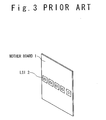
as follows. First, LSIs 2 are installed on one plane
of each of motherboards 1 (1a and 1b) as shown in Fig.
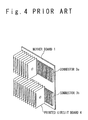
3. Next, as shown in Fig. 4, a plurality of the
printed circuit boards 4 are installed through
connectors 3 (3a and 3b) on the other plane of the
motherboard 1, that is, a back plane on which the LSIs
2 are installed. The printed circuit boards 4 are
arranged in the vertical direction to the motherboard
1 through the connectors 3. Referring to Fig. 5,
another motherboard 1 on which LSIs 2 are arranged on
one plane is arranged in parallel to the motherboard
1.
Here, the electronic unit shown in Fig. 5
will be described in detail. In Fig. 5, the
motherboards 1a and 1b are circuit boards on which the
connectors 3a and 3b are installed. The printed
circuit board 4 is a circuit board on which electronic
parts such as LSIs 2 are mounted. An air-cooling
system is necessary to cool the parts since the
electronic parts such as the LSIs 2 generate heat.
The motherboards 1a and 1b include the connectors 3a
and 3b, and wiring patterns (not shown). The
connectors 3a are arranged adjacent to the connectors
3b on the motherboards 1a and 1b. Specifically, a row
of the connectors 3b is arranged adjacent to the row
of the connectors 3a on a lower side of it. Regions
for the connectors 3a and 3b may overlap. In such a
case, the connectors 3a and 3b are alternately
arranged. The connector 3a and the connector 3b are
arranged in approximately parallel to each other.
However, the direction to insert the printed circuit
board 4 into the connector 3a is opposite to the
direction to insert the printed circuit board 4 into
the connector 3b. Therefore, a different kind of
printed circuit boards 4 are possibly inserted from
both ends of the motherboards 1a and 1b. The printed
circuit boards 4 inserted in the connectors 3b and the
printed circuit boards 4 inserted in the connectors 3a
can be electrically connected to each other through
the motherboards 1a or 1b. The structure shown in Fig
5 may be modified such that the connectors 3a are
arranged in a region adjacent to the longer side of
the connectors 3b.
Next, the connector 3 will be simply
described below. Fig. 6 is a perspective view of the
connector 3. The connector 3 is supported on the
motherboard 4 as a support member. The connector 3 is
a female connector 62. The female connector 62 has an
opening 67 in one shorter side to receive the edge 69
of the printed circuit board 4. Guides 68 extend
along the longer side of the female connector 62 from
the opening 67. The printed circuit board 4 is slid
in the longitudinal direction of the female connector
62 along the guides 68. The guides 68 guide the
printed circuit board 4 to an engagement position.
The connector 3 shown in Fig. 6 has a fixing part to
fix the edge 69 of the printed circuit board 4 to the
female connector 62 at the engagement position of the
connector 3. The fixing part includes a terminal
opening and shutting part 64 and terminals 63. The
terminals 63 can fix or release the edge 69 of the
printed circuit board 4 according to the operation of
the terminal opening and shutting part 64.
The opening and shutting part 64 is operated
when the edge 69 of the printed circuit board 4 is
inserted into the female connector 62, or the edge 69
of the printed circuit board 4 is released or pulled
out from the female connector 62. The terminals 63
are opened in the direction perpendicular to the
longitudinal direction of the female connector 62
through the operation of the opening and shutting part
64.
On the other hand, when the edge 69 of the
printed circuit board 4 is fixed to the female
connector 62, the opening and shutting mechanism 64 is
operated again. The terminals 63 are closed into the
direction perpendicular to the female connector 62
through the operation of the opening and shutting part
64. The printed circuit board 4 has terminals 65 to
be connected with the female connector 62 along the
edge 69 of the printed circuit board 4. The edge 69
of the printed circuit board 4 is inserted from the
opening 67 of the female connector 62 when the
terminals 63 of the female connector 62 are opened.
The edge 69 of the printed circuit board 4 is slid
into the female connector 62 in the longitudinal
direction of the female connector 62. When the
printed circuit board 4 is inserted to the engagement
position, the terminals 65 of the printed circuit
board 4 and the corresponding terminals 63 of the
connector 62 face to each other at the engagement
position. After the printed circuit board 4 has been
inserted to the engagement position, the opening and
shutting part 64 is operated. The terminals 63 are
closed through the operation of the opening and
shutting part 64. The edge 69 of the printed circuit
board 4 is fixed to the female connector 62 according
to the closed state of the terminals 63. Thus, the
terminals 63 and the terminals 65 are respectively
connected electrically.
The printed circuit board 4 has terminals 65
at both ends when each of the motherboards 1 has the
connectors, as shown in Fig. 5.
When the electronic unit shown in Fig. 5 is
installed in the conventional accommodation apparatus,
maintenance from four planes is needed of planes on
which the LSIs 2 are installed, and planes for
inserting and pulling out the printed circuit boards
4. In this case, a maintenance space cannot be
secured when a plurality of accommodation apparatuses
are provided adjacent to each other. Therefore, the
plurality of accommodation apparatuses are arranged
not to be adjacent. Thus, it is hard to provide many
accommodation apparatuses in a limited space.
In conjunction with the above description,
Japanese Laid Open Patent Application (JP-P2000-353883A)
discloses an electronic apparatus and a
maintenance method in order to solve the problem of
securing the maintenance space. This conventional
example aims improvement of accommodation efficiency
of the electronic apparatus and simplification of the
maintenance. A unit is rotated in the front
direction.
Also, Japanese Laid Open Utility Model
Application (JP-U-Showa 64-6084) discloses a rotation
setting mechanism of an electronic unit chassis. This
application aims to facilitate check and maintenance
of the electronic unit in a narrow space such as
inside of a ship. The electronic unit chassis
includes slide rails and a rotation shaft. The
electronic unit chassis is maintained from a single
plane of the chassis from which circuit boards are
installed. The electronic unit chassis is pulled out
in the front direction of a cabinet by using slide
rails provided on the both sides of the electronic
unit chassis. In addition, the electronic unit
chassis is inclined to the front direction. The
inclination of the electronic unit chassis is set to
an optional angle within the range of 90°. As a
result, the check and maintenance can be carried out
by connecting a test board with the circuit board from
the front direction.
Also, Japanese Laid Open Utility Model
Application (JP-U-A-Heisei 1-93778) discloses an
accommodation pulling-out mechanism. This
conventional example aims to improve maintenance
efficiency of an apparatus. Guide foots are provided
for each of electronic units accommodated in a chassis
to support rotation of the unit in a vertical
direction. Also, guide grooves are provided on a base
as a bottom section of the chassis. By providing the
guide foots on the guide grooves, the electronic unit
can be moved along the guide grooves in the chassis,
and can be rotated around the vertical axis. As a
result, it is no need to pull out the electronic unit
to outside of the chassis every time the maintenance
is carried out.
An object of the present invention is to
provide an accommodation apparatus which allows
maintenance of an electronic unit being maintained
from at least three planes to be carried out in a
small space.
In an aspect of the present invention, an
accommodation apparatus accommodates a unit which
needs maintenance from at least three planes. The
accommodation apparatus includes a chassis, a first
frame structure configured to accommodate the unit,
and a supporting mechanism coupled to the first frame
structure and the chassis to support the first frame
structure to the chassis such that at least one of
attitude and position of the unit is changeable with
respect to the chassis.
Here, it is preferable that the supporting
mechanism rotatably supports the first frame
structure.
Also, the supporting mechanism may include a
rotation axis coupled to the first frame structure,
and bearings coupled to the chassis to receive the
rotation axis. The rotation axis passes through a
center of gravity of the unit.
Also, the supporting mechanism may include a
first pulley coupled to the first frame structure and
provided on a rotation axis passing through a center
of gravity of the unit, second pulleys coupled to the
chassis, and a torque transfer member hung to the
first and second pulleys. The first pulley is
connected to the second pulleys by the torque
transfer member.
Also, the supporting mechanism may include a
first gearwheel coupled to the first frame structure
and provided on a rotation axis passing through a
center of gravity of the unit, second gearwheels
coupled to the chassis, and a chain hung to the first
and second pulleys. The first pulley is connected to
the second gearwheels by the chain.
Also, the supporting mechanism may include
first and second circular arcs coupled to the first
frame structure, wherein a center position of the
first and second circular arcs passes through a center
of gravity of the unit, and bearings coupled to the
chassis. The first frame structure is rotated when
the first and second circular arcs are moved through
the bearings.
Also, the chassis may further include a
second frame structure configured to accommodate the
first frame structure, and slide rails configured to
allow the second frame structure to slide on the slide
rails such that the unit is pulled out.
Also, when the chassis further includes a
second frame structure configured to accommodate the
first frame structure, and slide rails configured to
allow the second frame structure to slide on the slide
rails such that the unit is pulled out, the bearings
may be provided for the second frame structure.
Also, when the chassis further includes a
second frame structure configured to accommodate the
first frame structure, and slide rails configured to
allow the second frame structure to slide on the slide
rails such that the unit is pulled out, the second
pulleys may be provided for the second frame
structure.
Also, when the chassis further includes a
second frame structure configured to accommodate the
first frame structure, and slide rails configured to
allow the second frame structure to slide on the slide
rails such that the unit is pulled out, the second
gearwheels may be provided for the second frame
structure.
Also, when the chassis further includes a
second frame structure configured to accommodate the
first frame structure, and slide rails configured to
allow the second frame structure to slide on the slide
rails such that the unit is pulled out, the bearings
may be provided for the second frame structure.
Also, the torque transfer member may be a
belt or a wire.
Also, each of the bearings may include a
bearing body provided for the chassis to have a
surface corresponding to a corresponding one of the
first and second circular arcs, and balls provided
between the corresponding one of the first and second
circular arcs and the bearing body. Each of the first
and second circular arcs and the bearings may have a
groove with a semicircular cross section. Instead,
each of the first and second circular arcs and the
bearings may have a groove with a cuneal cross
section.
Also, each of the bearings may include a
bearing body provided for the chassis to have a
surface corresponding to a corresponding one of the
first and second circular arcs, and rollers provided
between the corresponding one of the first and second
circular arcs and the bearing body.
Also, each of the bearings may include a
bearing body provided for the chassis to have a
surface corresponding to a corresponding one of the
first and second circular arcs, and a spacer provided
between the corresponding one of the first and second
circular arcs and the bearing body.
Also, a rotation direction of the first frame
structure is preferably orthogonal to a direction of
the slide rails.
Hereinafter, an accommodation apparatus of an
electronic unit of the present invention will be
described in detail with reference to the attached
drawings.
Figs. 7 and 8 are schematic diagrams showing
the accommodation apparatus according to the first
embodiment of the present invention. Fig. 7 shows the
entire of an electronic unit installed in a first
frame structure 150. The electronic unit 154 is
exemplified by an above-mentioned conventional unit
which needs maintenance from four planes of the unit
154. In other words, a plurality of printed circuit
boards 162 are arranged between the two motherboards
160 which have a plurality of LSIs 102. Side
plates 161 are provided for the first frame structure.
The side board 161 is connected to a plane including
the side edges of the two motherboards 160. A
rotation axis 151 as a component of a supporting
mechanism is provided for the side plates 161 to pass
through the center of gravity of the electronic unit
154. The entire electronic unit 154 is accommodated
in the first frame structure 150 which is accommodated
in the chassis 170 of the accommodation apparatus.
The electronic unit 154 to be installed in the first
frame structure 150 needs maintenance from at least
three planes of the unit 154. However, the electronic
unit 154 is not limited to the above-mentioned
electronic unit.
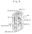
Referring to Fig. 8, bearings 152 as
components of the supporting mechanism are provided in
second frames 153 of a second frame structure and the
frames 153 are arranged on both sides of the chassis
170 of the accommodation apparatus. Thus, the
electronic unit 154 is accommodated in the chassis
170. The rotation axis 151 is supported by the
bearings 152. Thus, the electronic unit 154 can be
rotated around the rotation axis 151 by the bearings
152 in a state that the electronic unit 154 is
accommodated in the chassis 170. As for the
structures of the rotation axis 151 and the bearings
152, a smoother movement is achieved by using bearings
or bushes made of a metal or a nylon and the like (not
shown).
In this state, the maintenance of the LSIs
102 on the surfaces of the motherboards 160 can be
carried out from the front and back planes of the
chassis 170 as the maintenance planes. However, when
it is possible to rotate the electronic unit 154 in
the chassis into the front and back directions by 90°
or more, the maintenance can be carried out on only
the front plane side of the accommodation apparatus.
In the operation of the electronic unit 154,
a power supply unit 180 and cooling fan units 190 are
installed in the chassis 170 in addition to the
electronic unit 154. In this case, as shown in Fig.
8, the electronic unit 154 is fixed to the chassis 170
such that the printed circuit boards 162 can be
inserted and pulled out from the unit 154 in upward
and downward directions. The cooling fan units 190
are installed in the top and bottom of the chassis
170, and generate air-flows along the printed circuit
boards 162 for an effective cooling effect.
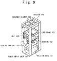
Fig. 9 shows a state that the electronic unit
154 is fallen down to the front direction by pulling
the top end of the electronic unit 154 accommodated in
the chassis 170 in the first embodiment. In this
case, the rotation of the electronic unit 154 is easy
since the rotation axis 151 is provided to pass
through the center of the gravity of the electronic
unit 154.
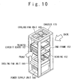
Fig. 10 shows a state that the motherboards
160 are in the horizontal planes by the rotating of
the electronic unit 154 by 90° from the state of Fig.
8. In this state, the maintenance of the printed
circuit boards 162 between the motherboards 160
becomes possible if the front and back planes of the
chassis 170 are used for the maintenance planes. In
this case, since the maintenance planes of the
accommodation apparatus are limited to the front and
back planes, other accommodation apparatuses can be
provided in adjacent in the right and left directions.
As a result, the space to provide the accommodation
apparatuses can be reduced.
However, when the electronic unit 154 can be
rotated in each of the front and back directions by
90° or more in the chassis 170, the maintenance can be
carried out on only the front side of the chassis 170.
Thus, four planes of the electronic unit 154 can be
maintained without increasing maintenance planes of
the accommodation apparatus or the space for
maintenance by adopting a mechanism for rotating the
electronic unit 154 in the chassis 170.
Figs. 11 to 13 are schematic diagrams showing
the accommodation apparatus according to the second
embodiment of the present invention. The basic
structure of the accommodation apparatus in the second
embodiment is the same as that in the first embodiment
other than the supporting mechanism.
Fig. 11 shows the entire of the accommodation
apparatus in the second embodiment. The supporting
mechanism in the first embodiment has the rotation
axis and the bearings. On the other hand, in the
second embodiment, the supporting mechanism has a belt
255, a first pulley 256, and second pulleys 257 (not
shown in Fig. 11).
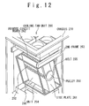
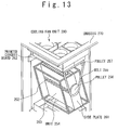
Figs. 12 and 13 are enlarged views of the
supporting mechanism in the second embodiment. The
first pulley 256 is provided on the side plate 261 on
the position passing through the center of the gravity
of an electronic unit 254. Second frames 253 of a
second frame structure are provided in the chassis
270. The second pulleys 257 are provided on the
second frame 253. In addition, the first pulley 256
is suspended by the belt 255 which is hung to the
second pulleys 257. As a result, the electronic unit
254 is supported by the chassis 270. Here, the
supporting mechanism may have a chain or a wire in
place to the belt 255, and gearwheels in place to the
pulleys in the second embodiment, although these
examples are not shown. Either or all of the second
pulleys 257 and the first pulley 256 are rotated, and
the electronic unit 254 suspended by the belt 255 is
rotated. As a result, the electronic unit 254 is
rotated in a vertical plane with respect to the
chassis 270.
When the motherboards 260 of the electronic
unit 254 are in the horizontal state to the chassis,
the front and back planes of the chassis 270 become
the maintenance planes to maintain the printed circuit
boards 262. Similarly, when the motherboards 260 of
the electronic unit 254 are in the vertical state to
the chassis, the front and back planes of the chassis
270 become the maintenance planes to maintain the LSIs
202 on the side surfaces of the motherboards 260.
However, when it is possible to rotate the electronic
unit 254 in the chassis in each of the front and back
directions by 90° or more, the maintenance can be
carried out on only the front side of the
accommodation apparatus.
In this way, the maintenance of the
electronic unit 254 from four planes can be carried
out without increasing maintenance planes of the
accommodation apparatus or the space for the
maintenance by providing the mechanism for rotating
the electronic unit 254 in the chassis. Also, the
supporting mechanism in the second embodiment has
larger area to support the weight of the electronic
unit 254 than in the first embodiment. Therefore, a
heavier unit can be installed in the accommodation
apparatus.
Figs. 14 to 16 are schematic diagrams showing
the accommodation apparatus according to the third
embodiment of the present invention. The basic
structure of the accommodation apparatus in the third
embodiment is the same as those in the first and
second embodiments other than the supporting
mechanism.
Fig. 14 shows the entire view of the
accommodation apparatus in the third embodiment. The
accommodation apparatus in the first embodiment has
the rotation axis and the bearings as the supporting
mechanism. On the other hand, in the third
embodiment, the supporting mechanism has circular arc
axis 358 and 359, and bearings 366 and 367.
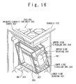
Figs. 15 and 16 are enlarged views of the
supporting mechanism in the third embodiment. The
upper side circular arc 358 and the lower side
circular arc 359 are provided on the side plate 361
such that a center of the upper side circular arc 358
and the lower side circular arc 359 passes through is
coincident with the center of the gravity of the
electronic unit 254. Two supporting columns 365 are
provided for a chassis 370 to oppose to each other.
An upper side bearing 366 to support the upper side
circular arc 358 and a lower side bearing 367 to
support the lower side circular arc 359 are
respectively provided on the two supporting columns
365. An upper surface of the upper side bearing 366
has a same curvature radius as that of the under
surface of the upper side circular arc 358.
Similarly, an upper surface of the lower side bearing
367 has a same curvature radius as that of the undersurface
of the lower side circular arc 359. The upper
side circular arc 358 and the lower side circular arc
359 provided on the side plate 361 slide on the upper
side bearing 366 and the lower side bearing 367. As a
result, the electronic unit 354 is rotated in a
vertical plane with respect to the chassis 370. In
this case, the upper side circular arc 358 and the
lower side circular arc 359 are long enough to
satisfy a rotating angle of the electronic unit 354
respectively.
When the motherboard 360 of the electronic
unit 354 is in the horizontal state to the chassis
370, the front and back planes of the chassis 370
become the maintenance planes to maintain the printed
circuit boards 362. Similarly, when the motherboard
360 of the electronic unit 354 is in the vertical
state to the chassis 370, the front and back planes of
the chassis 370 become the maintenance planes to
maintain the LSIs 302 on the surfaces of the
motherboards 360. However, when it is possible to
rotate the electronic unit 354 in the chassis 370 into
each of the front and back directions by 90° or more,
the maintenance can be carried out at only the front
plane of the accommodation apparatus.
In this way, four planes of the electronic
unit 354 can be maintained without increasing
maintenance planes of the accommodation apparatus or
the space for the maintenance by providing the
mechanism for rotating the electronic unit 354 in the
chassis 370. Also, the supporting mechanism in the
third embodiment has larger area than that of the
rotation axis 151 shown in the first embodiment to
support the weight of the electronic unit 354.
Therefore, a heavier electronic unit can be installed
in the accommodation apparatus.
Moreover, the upper side circular arc 358 and
the lower side circular arc 359 may not necessarily be
supported by the upper side bearing 366 and the lower
side bearing 367, respectively. That is, as shown in
Figs. 17A to 18B, the upper side circular arc 358 and
the lower side circular arc 359 may be supported
through balls 368, a cylindrical member 369 or a
spacer.
Here, the mechanism providing the balls 368
between the lower side circular arc 359 and the lower
side bearing 367 will be described. This is also
applied to the upper side circular arc 358 and the
upper side bearing 366.
Moreover, Fig. 17A is a cross sectional view of
the support mechanism on the perpendicular plane to
the rotation axis. Fig. 17B is a cross sectional view
of the support mechanism provided with the balls 368
between the lower side circular arc 359a and the lower
side bearing 367a on the vertical plane including the
rotation axis. Referring to Figs. 17A and 17B, the
plurality of balls 368 are provided between the lower
side circular arc 359a and the lower side bearing
367a, and arc grooves are formed in the opposing
surfaces of the lower side circular arc 359a and the
lower side bearing 367a. The rotation of the
electronic unit 354 becomes smoother by providing the
plurality of balls 368.
Fig. 18A is a cross sectional view of the
support mechanism on the perpendicular plane to the
rotation axis. Fig. 18B is a cross sectional view of
the support mechanism provided with the balls 368
between the lower side circular arc 359a and the lower
side bearing 367a on the vertical plane including the
rotation axis. Here, grooves shown in Fig. 18B are
different from those shown in Fig. 17B. In Fig. 17B,
the arc grooves are formed on the opposing surfaces of
the lower side circular arc 359a and the lower side
bearing 367a. On the other hand, the grooves shown in
Fig. 18B are formed in cuneal in this example. The
plurality of balls 368 are provided between the lower
side circular arc 359b and the lower side bearing
367b. Thus, the rotation of the electronic unit 354
becomes smoother by providing the plurality of balls
368.
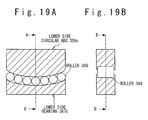
Fig. 19A is a cross sectional view of the
mechanism provided with a plurality of rollers 369
between the lower side circular arc 359c and the lower
side bearing 367c on the perpendicular plane to the
rotation axis. Also, Fig. 19B is a cross sectional
view of the mechanism on the vertical plane including
the rotation axis. The plurality of rollers 369 are
provided between the lower side circular arc 359c and
the lower side bearing 367c, and thus, the rotation of
the electronic unit 354 becomes smoother.
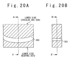
Fig. 20A is a cross sectional view of the
mechanism provided with a spacer 370 between the lower
side circular arc 359d and the lower side bearing 367d
on the perpendicular plane to the rotation axis.
Also, Fig. 20B is a cross sectional view of the
mechanism on the vertical plane including the rotation
axis. The spacer 370 is provided between the lower
side circular arc 359d and the lower side bearing
367d, and thus, the rotation of the electronic unit
354 becomes smoother.
It should be noted that in the third
embodiment, the circular arc is used. However, a
circle with no notch between the upper side circular
arc 358 and the lower side circular arc 359 may be
used.
Figs. 7A to 7D are schematic diagrams showing
the accommodation apparatus according to the fourth
embodiment of the present invention. In the basic
structure of the accommodation apparatus in the fourth
embodiment, an electronic unit 454 is supported by the
first frame structure which is supported by third
frames 472 of the second frame structure. Also, the
second frame structure is movably slid out from the
chassis 470 by using slide rails 471.
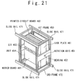
Fig. 21 shows the whole structure of the
electronic unit 454 in the fourth embodiment. The
electronic unit 454 is the same as the electronic unit
154 in the first embodiment. The electronic unit 454
is not installed directly in the chassis 470 but
installed in the first frame structure which is
accommodated in the second frame structure 472 with
bearings 452. The rotation axis 451 of the electronic
unit 454 as a component of the supporting mechanism is
arranged to be received by the bearings 452 of the
second frame structure 472 as another component of the
supporting mechanism, and the electronic unit 454 can
be rotated around the rotation axis 451 in the second
frame structure 472. Moreover, a fixing section of
the slide rails 471 that can be expanded and
contracted is provided for the chassis 470, and a
moving section of the slide rails 471 is provided for
the second frame structure 472. As a result, the
electronic unit 454 can be accommodated in the chassis
470 in a state that the electronic unit 454 is
installed in the first frame structure which is
accommodated in the second frame structure 472, and
can be pulled out in front of the chassis 470.
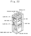
Fig. 22 shows the entire view of the
accommodation apparatus in the fourth embodiment. The
accommodation apparatus includes the second frame
structure 472 with the rotation axis 451 and the
bearings 452. As a result, the electronic unit 454
can be rotated around a horizontal rotation axis 451
of the second frame structure 472. Also, the
electronic unit 454 installed in the second frame
structure 472 can be pulled out in front of the
chassis 470 by using the slide rails 471.
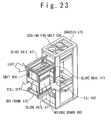
Fig. 23 shows the electronic unit 454 pulled
out in front of the chassis 470 by using the slide
rails 471. At this time, motherboard 460 in the
electronic unit 454 is supported in the vertical
direction. In such a state, LSIs 402 on the surface
of the motherboard 460 can be maintained. It should
be noted that the electronic unit 454 may be installed
so that the LSI-mounted plane of the motherboard 460
is directed to the front of the chassis 470 in the
third frame 472.
Fig. 24 shows the electronic unit 454 pulled
out in front of the chassis 470 is rotated by 90°, so
that the motherboard 460 is supported in the
horizontal state. In such a state, printed circuit
boards 462 can be maintained.
In the fourth embodiment, the electronic unit
454 is pulled out in front of the chassis 470 keeping
the unit 454 being accommodated in the third frame
472. Also, the electronic unit 454 can be rotated in
the third frame 472. As a result, four planes of the
electronic unit 454 can be maintained even if the
maintenance plane of the accommodation apparatus is a
front single plane.
Also, the direction of the pulling out of the
third frame 472 is approximately orthogonal to the
direction of the rotation of the electronic unit 454
in the third frame 472. That is, the direction of the
pulling out of the third frame 472 is approximately
parallel to the direction of the rotation axis of the
electronic unit 454 in the third frame 472.
Therefore, the maintenance space in front of the
accommodation apparatus becomes minimum for the
direction of pulling out of the third frame 472.
In this way, the maintenance can be carried
out at only the front plane of the chassis 470 though
the maintenance is carried out in the front and back
planes of the chassis in the first to second
embodiments.
Fig. 8 is a schematic diagram showing the
accommodation apparatus according to the fifth
embodiment of the present invention. The basic
structure of the accommodation apparatus in the fifth
embodiment is the same as that in the fourth
embodiment other than the supporting mechanism.
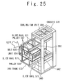
As shown in Fig. 25, the supporting mechanism
has a belt 555, a first pulley 556, and second pulleys
557. Therefore, the electronic unit 554 can be
rotated in the second frame structure 572. The
accommodation apparatus further has slide rails 571.
Therefore, the electronic unit 554 can be pulled out
in front of the chassis 570 accommodated in the second
frame structure 572 by using the slide rails 571.
Also, as shown in Fig. 8, the electronic unit 554 is
rotated in the second frame structure in the same
manner as the electronic unit 254 in the second
embodiment. Moreover, the second frame structure 572
accommodating the first frame structure which
accommodates the electronic unit 554 is pulled out
from the chassis 570 in the same manner in the fourth
embodiment.
It should be noted that the electronic unit
554 may be installed so that the LSI-mounted surface
of the motherboard is directed to the front of the
chassis in the third frame 572.
Also, in the fifth embodiment, the electronic
unit 554 is pulled out in front of the chassis 570.
The printed circuit board 562 can be maintained in the
state that the motherboards 560 are in the horizontal
state. Moreover, the electronic unit 554 pulled out
in front of the chassis 570 is rotated by 90°, and the
motherboards 560 are supported in the vertical state.
In such a state, the maintenance of the LSIs 502 on
the surfaces of the motherboards 560 can be carried
out.
As mentioned above, the electronic unit 554
is pulled out in front of the chassis 570. Moreover,
the electronic unit 554 pulled out can be rotated
around the horizontal axis. As a result, four planes
of the electronic unit 554 can be maintained even if
the maintenance plane of the accommodation apparatus
is only a single front plane.
In addition, the direction of the pulling out
of the third frame 572 is approximately orthogonal to
the direction of the rotation of the electronic unit
554 in the third frame 572. That is, the direction of
the pulling out of the third frame 572 is
approximately parallel to the rotation axis of the
electronic unit 554 in the third frame 572.
Therefore, the maintenance plane in front of the
chassis becomes minimum for the direction of pulling
out of the third frame 572.
In this way, the maintenance can be carried
out at only the front plane of the chassis 570 in the
fourth embodiment though the maintenance is carried
out at the front and back planes of the chassis in the
first to third embodiments.
Fig. 26 is a schematic diagram showing the
accommodation apparatus according to the sixth
embodiment of the present invention. The basic
structure of the accommodation apparatus in the sixth
embodiment is the same as in the fourth embodiment
other than the supporting mechanism.
As shown in Fig. 26, the supporting mechanism
has an upper side circular arc 658, a lower side
circular arc 659, upper side bearings 666, and lower
side bearings 667. As a result, the electronic unit
654 can be rotated in the second frame structure 672.
The accommodation apparatus further has slide rails
671. Therefore, the electronic unit 654 can be pulled
out in front of the chassis 670 in the state installed
in the first frame structure which is accommodated in
the third frame 672 by using the slide rails 671.
Also, as shown in Fig. 26, the electronic unit 654 is
rotated in the second frame structure in the same
manner as the electronic unit 354 in the third
embodiment. Moreover, the second frame structure 672
accommodating the electronic unit 654 is pulled out
from the chassis 670 in the same manner in the fourth
embodiment.
It should be noted that the electronic unit
654 may be installed so that the LSI-mounted surface
of the motherboard is directed to the front of the
chassis in the third frame 672. Further, the circular
arcs may be replaced by a circle as the supporting
mechanism that has no notch between the upper side
circular arc 658 and the lower side circular arc 659.
In the sixth embodiment, the electronic unit
654 is pulled out in front of the chassis 670. The
printed circuit boards 662 can be maintained in the
state that the motherboards 660 are in the horizontal
state. Moreover, the electronic unit 654 pulled out
in front of the chassis 670 is rotated by 90° and the
motherboards 660 are supported in the vertical state.
In such a state, the maintenance of the LSI 602 on the
surface of the motherboard 660 can be carried out.
As mentioned above, the electronic unit 654
is pulled out in front of the chassis 670. Moreover,
the electronic unit 654 can be rotated around the
horizontal axis in the state pulled out. As a result,
four planes of the electronic unit 654 can be
maintained only at a single front plane of the chassis
670.
In addition, the direction of the pulling out
of the third frame 672 is approximately orthogonal to
the direction of the rotation of the electronic unit
654 in the third frame 672. That is, the direction of
the pulling out of the third frame 672 is
approximately parallel to the rotation axis of the
electronic unit 654 in the third frame 672.
Therefore, the maintenance plane in front of the
chassis 670 becomes minimum for the direction of
pulling out of the third frame 672.
In this way, the maintenance can be carried
out at only the front plane of the chassis 670 in the
fifth embodiment though the maintenance is carried out
at the front and back planes of the chassis in the
first to third embodiments.
According to the present invention, the
electronic unit with maintenance planes of three or
more is supported by the chassis of the accommodation
apparatus. The maintenance plane of the electronic
unit to the chassis can be changed by the supporting
mechanism. Therefore, the electronic unit provided in
the chassis is efficiently maintained. Moreover, it
needs only a small space for the maintenance.
Claims (18)
- An accommodation apparatus accommodating a unit which needs maintenance from at least three planes, comprising:a chassis (170);a first frame structure (150) configured to accommodate said unit; anda supporting mechanism (151, 152; 255-257; 358, 359, 358, 359) coupled to said first frame structure and said chassis to support said first frame structure to said chassis such that at least one of attitude and position of said unit is changeable with respect to said chassis.
- The accommodation apparatus according to claim 1, wherein said supporting mechanism rotatably supports said first frame structure.
- The accommodation apparatus according to claim 1, wherein said supporting mechanism comprises:a rotation axis (151) coupled to said first frame structure; andbearings (152) coupled to said chassis to receive said rotation axis, andsaid rotation axis passes through a center of gravity of said unit.
- The accommodation apparatus according to claim 1, wherein said supporting mechanism comprises:a first pulley (256) coupled to said first frame structure and provided on a rotation axis passing through a center of gravity of said unit;second pulleys (257) coupled to said chassis; anda torque transfer member (255) hung to said first and second pulleys, andsaid first pulley is connected to said second pulleys by said torque transfer member.
- The accommodation apparatus according to claim 1, wherein said supporting mechanism comprises:a first gearwheel coupled to said first frame structure and provided on a rotation axis passing through a center of gravity of said unit;second gearwheels coupled to said chassis; anda chain hung to said first and second pulleys, andsaid first pulley is connected to said second gearwheels by said chain.
- The accommodation apparatus according to claim 1, wherein said supporting mechanism comprises:first and second circular arcs (358, 359) coupled to said first frame structure, wherein a center position of said first and second circular arcs passes through a center of gravity of said unit; andbearings (366, 367) coupled to said chassis, andsaid first frame structure is rotated when said first and second circular arcs are moved through said bearings.
- The accommodation apparatus according to claim 1, wherein said chassis further comprises:a second frame structure (472) configured to accommodate said first frame structure; andslide rails (471) configured to allow said second frame structure to slide on said slide rails such that said unit is pulled out.
- The accommodation apparatus according to claim 2, wherein said chassis further comprises:a second frame structure (472) configured to accommodate said first frame structure; andslide rails (471) configured to allow said second frame structure to slide on said slide rails such that said unit is pulled out.
- The accommodation apparatus according to claim 3, wherein said chassis further comprises:a second frame structure (472) configured to accommodate said first frame structure; andslide rails (471) configured to allow said second frame structure to slide on said slide rails such that said unit is pulled out, andsaid bearings are provided for said second frame structure.
- The accommodation apparatus according to claim 4, wherein said chassis further comprises:a second frame structure (472) configured to accommodate said first frame structure; andslide rails (471) configured to allow said second frame structure to slide on said slide rails such that said unit is pulled out, andsaid second pulleys are provided for said second frame structure.
- The accommodation apparatus according to claim 5, wherein said chassis further comprises:a second frame structure (472) configured to accommodate said first frame structure; andslide rails (471) configured to allow said second frame structure to slide on said slide rails such that said unit is pulled out, andsaid second gearwheels are provided for said second frame structure.
- The accommodation apparatus according to claim 6, wherein said chassis further comprises:a second frame structure (472) configured to accommodate said first frame structure; andslide rails (471) configured to allow said second frame structure to slide on said slide rails such that said unit is pulled out, andsaid bearings are provided for said second frame structure.
- The accommodation apparatus according to claim 4 or 10, wherein said torque transfer member is a belt or a wire.
- The accommodation apparatus according to claim 6 or 12, wherein each of said bearings comprises:a bearing body (367a) provided for said chassis to have a surface corresponding to a corresponding one of said first and second circular arcs; andballs (368) provided between the corresponding one of said first and second circular arcs and said bearing body, andeach of said first and second circular arcs and said bearings has a groove with a semicircular cross section.
- The accommodation apparatus according to claim 6 or 12, wherein each of said bearings comprises:a bearing body (367b) provided for said chassis to have a surface corresponding to a corresponding one of said first and second circular arcs; andballs (368) provided between the corresponding one of said first and second circular arcs and said bearing body, andeach of said first and second circular arcs and said bearings has a groove with a cuneal cross section.
- The accommodation apparatus according to claim 6 or 12, wherein each of said bearings comprises:a bearing body (367c) provided for said chassis to have a surface corresponding to a corresponding one of said first and second circular arcs; androllers (369) provided between the corresponding one of said first and second circular arcs and said bearing body.
- The accommodation apparatus according to claim 6 or 12, wherein each of said bearings comprises:a bearing body (367d) provided for said chassis to have a surface corresponding to a corresponding one of said first and second circular arcs; anda spacer (363) provided between the corresponding one of said first and second circular arcs and said bearing body.
- The accommodation apparatus according to any of claims 7 to 12, wherein a rotation direction of said first frame structure is orthogonal to a direction of said slide rails.
Applications Claiming Priority (2)
| Application Number | Priority Date | Filing Date | Title |
|---|---|---|---|
| JP2004087838 | 2004-03-24 | ||
| JP2004087838A JP4158155B2 (en) | 2004-03-24 | 2004-03-24 | Equipment for mounting electronic equipment |
Publications (1)
| Publication Number | Publication Date |
|---|---|
| EP1583410A2 true EP1583410A2 (en) | 2005-10-05 |
Family
ID=34879881
Family Applications (1)
| Application Number | Title | Priority Date | Filing Date |
|---|---|---|---|
| EP05090069A Withdrawn EP1583410A2 (en) | 2004-03-24 | 2005-03-17 | Accommodation apparatus of electronic unit |
Country Status (3)
| Country | Link |
|---|---|
| US (1) | US7360660B2 (en) |
| EP (1) | EP1583410A2 (en) |
| JP (1) | JP4158155B2 (en) |
Families Citing this family (6)
| Publication number | Priority date | Publication date | Assignee | Title |
|---|---|---|---|---|
| JP4662549B2 (en) * | 2005-10-07 | 2011-03-30 | 株式会社日立製作所 | Storage controller |
| JP4776472B2 (en) * | 2006-08-18 | 2011-09-21 | 株式会社日立製作所 | Storage device |
| US20100091458A1 (en) * | 2008-10-15 | 2010-04-15 | Mosier Jr David W | Electronics chassis with angled card cage |
| US7893365B2 (en) * | 2008-11-10 | 2011-02-22 | Adc Telecommunications, Inc. | Weather resistant variable enclosure frame |
| JP5292321B2 (en) * | 2010-01-13 | 2013-09-18 | アラクサラネットワークス株式会社 | Communication device |
| JP6254435B2 (en) * | 2013-12-13 | 2017-12-27 | Necプラットフォームズ株式会社 | Electronic device and unit mounting structure |
Family Cites Families (8)
| Publication number | Priority date | Publication date | Assignee | Title |
|---|---|---|---|---|
| JPH0521916Y2 (en) | 1987-06-30 | 1993-06-04 | ||
| JPH0193778U (en) | 1987-12-15 | 1989-06-20 | ||
| US5140501A (en) * | 1988-04-30 | 1992-08-18 | Fujitsu Limited | Mechanism for inserting and withdrawing printed board unit of electronics circuit device |
| US6128196A (en) * | 1998-04-27 | 2000-10-03 | Stratus Computer, Inc. | Circuit board chassis |
| JP3397302B2 (en) | 1999-06-09 | 2003-04-14 | 日本電気株式会社 | Multilayer piezoelectric ceramic transformer and method of manufacturing the same |
| JPWO2002098198A1 (en) * | 2001-05-25 | 2004-09-16 | 三菱電機株式会社 | Subrack and subrack guide plate |
| US7000883B2 (en) * | 2003-01-17 | 2006-02-21 | The Insitu Group, Inc. | Method and apparatus for stabilizing payloads, including airborne cameras |
| US6937467B2 (en) * | 2003-08-27 | 2005-08-30 | Inventec Corporation | Device for fastening adapter cards at a positioning frame of computer case |
-
2004
- 2004-03-24 JP JP2004087838A patent/JP4158155B2/en not_active Expired - Fee Related
-
2005
- 2005-03-16 US US11/080,559 patent/US7360660B2/en not_active Expired - Fee Related
- 2005-03-17 EP EP05090069A patent/EP1583410A2/en not_active Withdrawn
Also Published As
| Publication number | Publication date |
|---|---|
| JP4158155B2 (en) | 2008-10-01 |
| US20050211869A1 (en) | 2005-09-29 |
| JP2005277086A (en) | 2005-10-06 |
| US7360660B2 (en) | 2008-04-22 |
Similar Documents
| Publication | Publication Date | Title |
|---|---|---|
| JP4545191B2 (en) | Communication apparatus and information processing apparatus | |
| US8897017B2 (en) | Serviceable hard disk drive trays for a server rack | |
| US10687439B2 (en) | High-density server with redundant power source for server modules | |
| US10765038B1 (en) | Floating liquid-cooled cold plate | |
| US20090152216A1 (en) | Rack system providing flexible configuration of computer systems with front access | |
| EP0635836A1 (en) | Magnetic disk apparatus | |
| EP3367766B1 (en) | Symmetrical sled blind mating in unsymmetrical chassis placement | |
| US6466448B1 (en) | Riser board retaining and air ducting structure for printed circuit boards | |
| EP1583410A2 (en) | Accommodation apparatus of electronic unit | |
| US20130039002A1 (en) | Server rack assembly | |
| US6781827B2 (en) | Structure for mounting computer drive devices, pivotable between operating and service positions, and latchable in the service position | |
| JP4083445B2 (en) | Electronic device and device comprising a plurality of electronic devices | |
| US20040165366A1 (en) | Electronics assembly | |
| US10856409B1 (en) | Foldable board with flexible PCB coupling | |
| US20250185201A1 (en) | Sled, orthogonal-direct chassis, and methods | |
| JP2526654B2 (en) | Electronic circuit package cage structure | |
| CN110794928B (en) | Support device | |
| CN1991673A (en) | Housing for rack mounted device | |
| US6950301B2 (en) | Alignment docking system | |
| US12389561B1 (en) | Compute and/or storage rack-wall | |
| US4135225A (en) | Pivotal structural enclosure | |
| US12621951B2 (en) | Server device | |
| CN219960989U (en) | A split communication cabinet | |
| CN224217049U (en) | Electronic Device and Portable Display Adapter Stand | |
| TWI892493B (en) | Gpu module and 2u server |
Legal Events
| Date | Code | Title | Description |
|---|---|---|---|
| PUAI | Public reference made under article 153(3) epc to a published international application that has entered the european phase |
Free format text: ORIGINAL CODE: 0009012 |
|
| AK | Designated contracting states |
Kind code of ref document: A2 Designated state(s): AT BE BG CH CY CZ DE DK EE ES FI FR GB GR HU IE IS IT LI LT LU MC NL PL PT RO SE SI SK TR |
|
| AX | Request for extension of the european patent |
Extension state: AL BA HR LV MK YU |
|
| STAA | Information on the status of an ep patent application or granted ep patent |
Free format text: STATUS: THE APPLICATION HAS BEEN WITHDRAWN |
|
| 18W | Application withdrawn |
Effective date: 20081020 |