EP1583361A2 - Image processing system, projector, information storage medium, and image processing method - Google Patents
Image processing system, projector, information storage medium, and image processing method Download PDFInfo
- Publication number
- EP1583361A2 EP1583361A2 EP05006633A EP05006633A EP1583361A2 EP 1583361 A2 EP1583361 A2 EP 1583361A2 EP 05006633 A EP05006633 A EP 05006633A EP 05006633 A EP05006633 A EP 05006633A EP 1583361 A2 EP1583361 A2 EP 1583361A2
- Authority
- EP
- European Patent Office
- Prior art keywords
- area
- projection
- image
- information
- sensing
- Prior art date
- Legal status (The legal status is an assumption and is not a legal conclusion. Google has not performed a legal analysis and makes no representation as to the accuracy of the status listed.)
- Withdrawn
Links
Images


Classifications
-
- H—ELECTRICITY
- H04—ELECTRIC COMMUNICATION TECHNIQUE
- H04N—PICTORIAL COMMUNICATION, e.g. TELEVISION
- H04N9/00—Details of colour television systems
- H04N9/12—Picture reproducers
- H04N9/31—Projection devices for colour picture display, e.g. using electronic spatial light modulators [ESLM]
- H04N9/3179—Video signal processing therefor
- H04N9/3185—Geometric adjustment, e.g. keystone or convergence
-
- H—ELECTRICITY
- H04—ELECTRIC COMMUNICATION TECHNIQUE
- H04N—PICTORIAL COMMUNICATION, e.g. TELEVISION
- H04N5/00—Details of television systems
- H04N5/74—Projection arrangements for image reproduction, e.g. using eidophor
-
- H—ELECTRICITY
- H04—ELECTRIC COMMUNICATION TECHNIQUE
- H04N—PICTORIAL COMMUNICATION, e.g. TELEVISION
- H04N9/00—Details of colour television systems
- H04N9/12—Picture reproducers
- H04N9/31—Projection devices for colour picture display, e.g. using electronic spatial light modulators [ESLM]
- H04N9/3191—Testing thereof
- H04N9/3194—Testing thereof including sensor feedback
Definitions
- the present invention relates to an image processing system, a projector, an information storage medium, and an image processing method in which the detection of a projection area is based on sensing information.
- a recent proposal for adjusting the position of a projection image involves using a projector that is provided with a CCD camera to project an image onto a projection target such as a screen, and using the CCD camera to sense the projected projection image and detect the coordinates of four corners of the projection-target area that correspond to the projection target within the sensing area.
- Japanese Patent Application Laid-Open No. 5-30520 proposes a configuration in which the position at which an image is projected is adjusted by displaying an image within an image-displayable area and sensing the entire image-displayable area.
- an image processing system comprising:
- a projector having the above image processing system.
- an information storage medium storing a program for causing a computer to function as:
- an image processing method for performing image processing based on a difference image which is a difference image between a first calibration image and a second calibration image, the difference image being configured of a center block area positioned around the center of the difference image, a peripheral block area positioned on a periphery of the center block area, and a background area which is an area other than the center block area and the peripheral block area, and each pixel in the center block area and the peripheral block area having a different index value from each pixel in the background area, the image processing method comprising:
- an image processing system comprising:
- a projector having the above image processing system.
- an information storage medium storing a program for causing a computer to function as:
- an image processing method comprising:
- Embodiments of the present invention were devised in the light of the above-described technical problems.
- the embodiments may provide an image processing system, a projector, an information storage medium, and an image processing method that enable the appropriate generation of positional information for a projection area, even when part of a projection image is displayed outside of a projection target.
- embodiments of the present invention may also provide an image processing system, a projector, an information storage medium, and an image processing method that enable the generation of positional information for the projection-target area in a shorter time and also accurately.
- an image processing system and a projector each of which comprising:
- an information storage medium storing a program for causing a computer to function as:
- an image processing method for performing image processing based on a difference image which is a difference image between a first calibration image and a second calibration image, the difference image being configured of a center block area positioned around the center of the difference image, a peripheral block area positioned on a periphery of the center block area, and a background area which is an area other than the center block area and the peripheral block area, and each pixel in the center block area and the peripheral block area having a different index value from each pixel in the background area, the image processing method comprising:
- the image processing system and the like generate positional information for the projection area by detecting a center reference position of a center block area that is smaller than the projection area corresponding to the projection image, even if part of the projection image is projected outside of the projection target.
- this embodiment enables the image processing system and the like to determine the position of the projection area based not only on a center reference position but also on a peripheral reference position of a peripheral block area that is positioned on the periphery thereof, the positional information of the projection area can be generated more precisely.
- this image processing system or the like could use images such that a monochrome image is used as the first calibration image; an image consisting of a center block area positioned in the vicinity of the center thereof, a peripheral block area positioned on the periphery of that center block area, and a background area that is an area other than the center block area and the peripheral block area is used as the second calibration image; where each pixel in the center block area and the peripheral block area has a different index value from each pixel in the background area.
- the projection area information generation means may generate the projection area information by setting a plurality of approximated straight lines or approximated curves based on the center reference positions and the peripheral reference positions and determining the shape or arrangement of the center block area and the peripheral block area.
- the image processing method may comprise:
- the projection area and the center block area may be rectangular areas
- the projection area information generation means may determine positions of four corners of the center block area by deriving intersections of the plurality of approximated straight lines or intersections of the plurality of approximated curves, and may generate the projection area information indicating positions of four corners of the projection area, based on the positions of the four corners of the center block area.
- the projection area and the center block area may be rectangular areas, the image processing method may comprise:
- the image processing system, the projector, and the information storage medium may further comprise:
- the image processing method may comprise:
- the peripheral reference position detection means and the image processing method could detect a peripheral reference position that is positioned closer to the boundary point than the center reference position.
- an image processing system and an projector each of which comprising:
- an information storage medium storing a program for causing a computer to function as:
- an image processing method comprising:
- the image processing system and the like can generate positional information for the projection-target area in a shorter time and also more accurately, by provisionally detecting the projection-target area based on low-resolution sensing information then detecting the projection-target area based on high-resolution sensing information in the vicinity of a boundary line thereof.
- the edge detection means may detect edges at a plurality of locations within a first sensed image based on the first sensing information, to generate the first edge detection information
- the projection-target area information generation means may generate the provisional detection information by setting a linear approximated straight line or linear approximated curve, based on positional information of the plurality of locations which is based on the first edge detection information.
- the image processing method may comprise:
- the projection-target area detection means may comprise detection point evaluation means for evaluating a plurality of edge detection points, and the detection point evaluation means may determine whether or not each of the plurality of edge detection points is distanced from the linear approximated straight line or the linear approximated curve by at least a predetermined value, and may control the projection-target area information generation means in such a manner that a detection point which is distanced by at least the predetermined value is excluded and the linear approximated straight line or the linear approximated curve is reset.
- the image processing method may comprise:
- the image processing system and the projector may further comprise:
- the information storage medium may store a program for causing a computer to function as:
- the image processing method may further comprise:
- the second calibration image may be configured of the center block area, a peripheral block area positioned on a periphery of the center block area, and a background area that is an area other than the center block area and the peripheral block area, each pixel in the center block area and the peripheral block area may have a different index value from each pixel in the background area, and the image processing system and the projector may comprise:
- the second calibration image may be configured of the center block area, a peripheral block area positioned on a periphery of the center block area, and a background area that is an area other than the center block area and the peripheral block area, each pixel in the center block area and the peripheral block area may have a different index value from each pixel in the background area, and the information storage medium may store a program for causing a computer to function as:
- the second calibration image may be configured of the center block area, a peripheral block area positioned on a periphery of the center block area, and a background area that is an area other than the center block area and the peripheral block area, each pixel in the center block area and the peripheral block area may have a different index value from each pixel in the background area, and the image processing method may further comprise:
- the image processing system and the like generate positional information for the projection area by detecting a center reference position of a center block area that is smaller than the projection area corresponding to the projection image, even if part of the projection image is projected outside of the projection target.
- this embodiment enables the image processing system and the like to determine the position of the projection area based not only on a center reference position but also on a peripheral reference position of a peripheral block area that is positioned on the periphery thereof, the positional information of the projection area can be generated more precisely.
- the projection area information generation means may generate the projection area information by setting a plurality of approximated straight lines or approximated curves based on the center reference positions and the peripheral reference positions and determining the shape or arrangement of the center block area and the peripheral block area.
- the image processing method may comprise:
- the projection area and the center block area may be rectangular areas
- the projection area information generation means may determine positions of four corners of the center block area by deriving intersections of the plurality of approximated straight lines or intersections of the plurality of approximated curves, and may generate the projection area information indicating positions of four corners of the projection area, based on the positions of the four corners of the center block area.
- the projection area and the center block area may be rectangular areas, and the image processing method may comprise:
- the image processing system and the projector may further comprise:
- the information storage medium may store a program for causing a computer to functions as:
- the image processing method may comprise:
- the peripheral reference position detection means and the image processing method could detect a peripheral reference position that is positioned closer to the boundary point than the center reference position.
- the image processing system and the projector may further comprise:
- the information storage medium may store a program for causing a computer to function as:
- the image processing method may comprise:
- FIG. 1 A schematic view of an image projection state of a first embodiment of the present invention is shown in Fig. 1.
- Fig. 2 A conceptual view of the positional relationship of a screen 10 and a projection image 12 in accordance with the first embodiment is shown in Fig. 2.
- a projector 20 projects an image towards the screen 10. This causes the display of the projection image 12 on the screen 10.
- the projector 20 of the first embodiment has a sensor 60 that is a sensing means.
- the sensor 60 senses the screen 10 on which the projection image 12 is displayed, through a sensing screen, and generates sensing information.
- the projector 20 adjusts the distortion and the display position of the projection image 12, based on the sensing information.
- a prior-art projector would be unable to adjust the distortion of the projection image 12 and the display position thereof, based on sensing information.
- the projector 20 of the first embodiment uses a calibration image that differs from that of the prior art in that it enables the determination of the position of the projection image 12 more precisely under a wider range of conditions than in the prior art, by implementing simple search processing based on sensing information of that calibration image.
- FIG. 3 A functional block diagram of the projector 20 in accordance with the first embodiment is shown in Fig. 3.
- the projector 20 comprises an input signal processing section 110 that converts analog RGB signals (R1, G1, and B1) into digital RGB signals (R2, G2, and B2); a color conversion section 120 that converts those digital RGB signals (R2, G2, and B2) into digital RGB signals (R3, G3, and B3), in order to correct the color and brightness of the image; an output signal processing section 130 that converts those digital RGB signals (R3, G3, and B3) into analog RGB signals (R4, G4, and B4); and an image projection section 190 that projects an image based on those analog RGB signals.
- an input signal processing section 110 that converts analog RGB signals (R1, G1, and B1) into digital RGB signals (R2, G2, and B2)
- a color conversion section 120 that converts those digital RGB signals (R2, G2, and B2) into digital RGB signals (R3, G3, and B3), in order to correct the color and brightness of the image
- an output signal processing section 130 that converts those digital RGB signals (R3, G3, and B3) into analog RGB signals (R4, G4, and B4)
- the image projection section 190 comprises a spatial light modulator 192, a drive section 194 for driving the spatial light modulator 192, a light source 196, and a lens 198.
- the drive section 194 drives the spatial light modulator 192, based on image signals from the output signal processing section 130.
- the image projection section 190 projects light from the light source 196 through the spatial light modulator 192 and the lens 198.
- the projector 20 also comprises a calibration information generation section 172 that generates calibration information for displaying first and second calibration images; the sensor 60 that generates sensing information for the calibration images; and a sensing information storage section 140 that temporarily stores sensing information from the sensor 60.
- the projector 20 further comprises a projection area detection section 150 that detects the position of the projection area in the sensing screen (sensing area) of the sensor 60, based on the sensing information.
- the projection area detection section 150 comprises a difference image generation section 152 that generates a difference image between a first sensed image and a second sensed image, a center reference position detection section 154 that detects a plurality of center reference positions of a center block area comprised within the difference image, a peripheral reference position detection section 156 that detects a plurality of peripheral reference positions of peripheral block areas comprised within the difference image, and a projection area information generation section 158 that generates projection area information indicating the position of the projection area, based on the reference positions.
- the projector 20 also has a function that corrects distortion of the projection image 12.
- the projector 20 comprises a luminance peak position detection section 164 that detects a luminance peak position (the position of the pixel at which the luminance value is a maximum) within the projection area, based on the projection area information; an image distortion correction amount calculation section 162 that calculates the amount of image distortion correction, based on the luminance peak position; and an image distortion correction section 112 that corrects the image signal, based on the image distortion correction amount.
- FIG. 4 A block diagram of hardware for the projector 20 of the first embodiment is shown in Fig. 4.
- the configuration could be implemented by using an A/D converter 930 and image processing circuit 970, or the like, as the input signal processing section 110; RAM 950 or the like as the sensing information storage section 140; the image processing circuit 970 or the like as the projection area detection section 150 and the luminance peak position detection section 164; a CPU 910 or the like as the image distortion correction amount calculation section 162; the image processing circuit 970 and the RAM 950, or the like, as the calibration information generation section 172; a D/A converter 940 or the like as the output signal processing section 130; a liquid-crystal panel 920 or the like as the spatial light modulator 192; and a ROM 960 or the like which stores a liquid-crystal light valve driver for driving the liquid-crystal panel 920, as the drive section 194.
- an information storage medium 900 which stores a program that causes a computer to function as components such as the difference image generation section 152 could be installed in the computer, and the computer reads out the program in order to function as the difference image generation section 152, etc.
- This information storage medium 900 could be a CD-ROM, DVD-ROM, ROM, RAM, or HDD, by way of example, and the method of reading the program therefrom could be a direct method or an indirect method.
- FIG. 5 A flowchart of position detection processing for the projection area in accordance with the first embodiment is shown in Fig. 5.
- a conceptual view of a first calibration image 13 is shown in Fig. 6A and a conceptual view of a second calibration image 14 is shown in Fig. 6B.
- the projector 20 first projects an all-white calibration image (in which the entire image is white), as shown in Fig. 6A, as the first calibration image 13 (step S1). More specifically, the calibration information generation section 172 generates calibration information (such as RGB signals) for the first calibration image 13 and the image projection section 190 projects an all-white calibration image based on that calibration information.
- the calibration information generation section 172 generates calibration information (such as RGB signals) for the first calibration image 13 and the image projection section 190 projects an all-white calibration image based on that calibration information.
- the sensor 60 senses the first calibration image 13 at an automatic exposure setting, and generates first sensing information (step S2).
- the sensing information storage section 140 stores the first sensing information.
- the projector 20 then projects the second calibration image 14 shown in Fig. 6B as the second calibration image 14 (step S3). More specifically, the calibration information generation section 172 generates calibration information for the second calibration image 14 and the image projection section 190 projects the second calibration image 14 based on that calibration information.
- the second calibration image 14 is a pattern image of a checker pattern such that, if the entire image is divided into nine equal blocks, the center block and the four peripheral block areas at the four corners are black and the remaining block areas are white.
- the sensor 60 senses the second calibration image 14 on the screen 10 at the same exposure as that for the first calibration image 13, and generates second sensing information (step S4).
- the sensing information storage section 140 stores the second sensing information.
- the difference image generation section 152 generates a difference image between the first calibration image 13 and the second calibration image 14, based on the first and second sensing information (step S5).
- this difference image is an image obtained by calculating differences such as those of luminance values for each pixel, by way of example.
- This difference image could be an image having a difference value for each pixel if that difference value exceeds a predetermined threshold at that pixel, but the value is zero at all other pixel positions, by way of example.
- the difference image generation section 152 need not necessarily calculate differences for the entire image; it could also calculate differences only within a area (a portion of the image) that is necessary for the processing described below.
- the projection area detection section 150 detects a plurality of center reference positions (four in this embodiment) of the center block area comprised within the difference image and a plurality of peripheral reference positions (eight in this embodiment) comprised within the difference image.
- FIG. 7 A conceptual view of a search method in a first stage in the detection of the center reference positions in the first embodiment is shown in Fig. 7.
- FIG. 8 A conceptual view of a search method in a second stage in the detection of the center reference positions in the first embodiment is shown in Fig. 8.
- the center reference position detection section 154 first detects the four center reference positions of the pattern image, in order to detect the position of the projection area (the area corresponding to the projection image 12) in a sensing area 15 corresponding to the sensing screen (step S6).
- a projection-target area (screen area) 18 is shown in these figures to facilitate comprehension of the description, but it is possible that the projection-target area 18 and some of peripheral block areas 17-1 to 17-4 that are outside of the projection-target area 18 will not exist in the difference image in practice.
- values such as xc, yp, and ym for the search reference position could be determined by the angle of view and position of each of the lens 198 and the sensor 60, or they could be determined by experimentation, or they could be determined based on experimentation, by way of example. This also concerns other search reference positions used later in this description.
- center reference position detection section 154 outputs center reference positional information indicating the four center reference positions P1 (xc, y1), P2 (xc, y2), P3 (x1, yc), and P4 (x2, yc) of the center block area 16 to the peripheral reference position detection section 156.
- the peripheral reference position detection section 156 detects the eight peripheral reference positions of the pattern image, based on the center reference positional information (step S7).
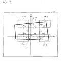
- FIG. 9 A conceptual view of a search method in a first stage in the detection of the peripheral reference positions in accordance with the first embodiment is shown in Fig. 9. Similarly, a conceptual view of a search method in a second stage in the detection of the peripheral reference positions in accordance with the first embodiment is shown in Fig. 10.
- peripheral reference position detection section 156 then outputs peripheral reference positional information indicating the coordinates of these eight points and center reference positional information to the projection area information generation section 158.
- the projection area information generation section 158 uses approximated straight lines (or approximated curves) based on the peripheral reference positional information and the center reference positional information, to detect the positions of the four corners of the projection area (step S8).
- FIG. 11 A conceptual view of a first stage of setting approximated straight lines in accordance with the first embodiment is shown in Fig. 11.
- FIG. 12 A conceptual view of a second stage of setting approximated straight lines in accordance with the first embodiment is shown in Fig. 12.
- the projection area information generation section 158 sets an approximated straight line, as shown by the broken line in Fig. 11, based on the coordinates of points P5, P3, and P6. By a similar method, the projection area information generation section 158 sets four approximated straight lines, as shown by the broken lines in Fig. 12, and identifies four intersections A (xA, yA) to D (xD, yD) between these approximated straight lines as the four corners of the center block area 16.
- E (xE, yE) (2*xA - xC, 2*yA - yc)
- F (xF, yF) (2*xB - xD, 2*yB - yD)
- G (xG, yG) (2*xC - xA, 2*yC - yA)
- H (xH, yH) (2*xD - xB, 2*yD - yB).
- this embodiment can detect the positions of the four corners of the projection area in the sensing area 15, inevitably when the projection image 12 is comprised within the screen 10, but also when part of the projection image 12 is displayed outside the screen 10.
- the projector 20 it is also possible for the projector 20 to convert the positional information of the projection area into the plane of the screen 10, to generate positional information for the four corners of the projection image 12.
- the luminance peak position detection section 164 is used to detect the luminance peak position at which the luminance value is at a maximum within the projection area within the sensing area, based on the sensing information for the first calibration image 13 and the projection area information that indicates the four corners of the projection area from the projection area information generation section 158.
- the center of the projection area would be the luminance peak position.
- the luminance values on the left side of the projection area are high, it is possible to determine that the optical axis of the projection has slipped toward the left from the center of the projection image 12, and thus it is possible to determined that the projection image 12 is deformed into a lozenge shape in which the left side is shorter and the right side longer.
- the distortion of the image can be determined by determining the luminance peak position within the projection area.
- the image distortion correction amount calculation section 162 calculates a correction amount corresponding to the image distortion, based on the luminance peak position within the projection area.
- the image distortion correction section 112 within the input signal processing section 110 then corrects the input image signal in such a manner that the distortion of the image is corrected, based on that correction amount.
- the projector 20 can correct distortion of the image, even when part of the projection image 12 is displayed outside of the screen 10. It should be obvious to those skilled in the art that the method of correcting image distortion is not limited to this method.
- the projector 20 could detect the pixel that has the greatest luminance value within the sensed image and base the correction of distortion of that image on the position of that pixel.
- the projector 20 could also identify the four corners of the projection area to a higher precision than that obtained by using a pattern image that has a feature only at the center, by using an image that has features at the periphery thereof in addition to the center, such as the pattern image shown in Fig. 6B.
- the projector 20 could also identify points at which the luminance value in the vicinity thereof changes.
- an approximated straight line is set by using a plurality of points at such a narrow spacing, an error of one pixel in a point that is the origin of the approximated straight line can have a greater effect than in an approximated straight line formed by using a plurality of points at a wider spacing.
- this embodiment enables the projector 20 to set approximated straight lines by using a plurality of points at wider spacing, by using the reference points of the center block area 16 and the reference points of the peripheral block areas 17-1 to 17-4, it is possible to identify the four corners of the projection area at a higher precision.
- this embodiment enables the projector 20 to detect the position of the projection area more easily and also more rapidly, by searching only the necessary areas of the difference image, not the entire difference image.
- the first sensing information can be generated at an exposure suited to the usage environment by sensing the all-white image at a temporary automatic exposure setting and generating the corresponding first sensing information, during the projection of the calibration images.
- the projector 20 can also generate the second sensing information at an exposure suited to the generation of the difference image, by generating the second sensing information at the exposure used during the sensing of the all-white image.
- the sensor 60 can utilize the dynamic range of the sensor 60 more effectively than in a method of sensing images at a fixed exposure, even when the screen 10 is affected by ambient light, when the reflection of the projected light is too weak because the projection distance is too great or the reflectivity of the screen 10 is too low, or when reflection of the projected light is too strong because the projection distance is too close or the reflectivity of the screen 10 is too high.
- the searching can be done in any sequence, so that the projector 20 could first search in the lateral direction with respect to the difference image to detect a center reference position or a peripheral reference position, then base a search in the vertical direction on that center reference position or that peripheral reference position.
- the projector 20 could perform various different processings by using the positional information for the projection area, such as correcting color variations within the projection area or detecting an indicated position within the projection area, based on the projection area information, other than the correction of image distortion based on the projection area information.
- the projector 20 could also detect the projection area after detecting the projection-target area 18.
- FIG. 13 A functional block diagram of the projector 20 in accordance with a modification of the first embodiment is shown in Fig. 13.
- Fig. 14 A conceptual view of a search method in a first stage in the detection of the peripheral reference positions in this modification of the first embodiment is shown in Fig. 14.
- Fig. 15 A conceptual view of a search method in a second stage in the detection of the peripheral reference positions in this modification of the first embodiment is shown in Fig. 15.
- a projection-target area boundary point detection section 159 is provided within the projection area detection section 150, as shown by way of example in Fig. 13.
- the center reference position detection section 154 outputs center reference positional information to the projection-target area boundary point detection section 159.
- a generic method is used in the edge detection. This identifies points T, U, V, and W, as shown in Fig. 14.
- the projection-target area boundary point detection section 159 outputs projection-target area boundary point information indicating the positions of the points T, U, V, and W to the peripheral reference position detection section 156.
- the peripheral reference position detection section 156 identifies the remaining four points P9 to P12 by a similar method.
- the projection area detection section 150 can identify the center reference positions of the center block area 16 and the peripheral reference positions of the peripheral block areas 17-1 to 17-4 by such a method, to identify the positions of the four corners of the projection area.
- such a method enables the projection area information generation section 158 to avoid unwanted processing for detecting peripheral reference positions outside the projection-target area, in comparison with the previously described method, and also enables it to obtain an approximated straight line in a state in which the three points for deriving that approximated straight line are further apart. This enables the projector 20 to detect the position of the projection area to a higher precision.
- the projector 20 in accordance with the second embodiment determines the positional relationship between the screen 10 and the projection image 12 and also the shape of the projection image 12, based on sensing information, and adjusts distortion of the projection image 12 and the display position thereof.
- the projector 20 of the second embodiment generates positional information for a projection-target area (an area corresponding to the screen 10) in a projection-target area within the sensing area of the sensor 60 and a projection area (an area corresponding to the projection image 12), within a shorter time and also more accurately, by performing image processing that differs from that in the prior art.
- FIG. 16 A functional block diagram of the projector 20 of the second embodiment is shown in Fig. 16.
- the projector 20 comprises the input signal processing section 110 that converts analog RGB signals (R1, G1, and B1) that are input from a personal computer (PC) or the like, into digital RGB signals (R2, G2, and B2); the color conversion section 120 that converts those digital RGB signals (R2, G2, and B2) into digital RGB signals (R3, G3, and B3), in order to correct the color and brightness of the image; the output signal processing section 130 that converts those digital RGB signals (R3, G3, and B3) into analog RGB signals (R4, G4, and B4); and the image projection section 190 that projects an image based on those analog RGB signals.
- the input signal processing section 110 that converts analog RGB signals (R1, G1, and B1) that are input from a personal computer (PC) or the like, into digital RGB signals (R2, G2, and B2)
- the color conversion section 120 that converts those digital RGB signals (R2, G2, and B2) into digital RGB signals (R3, G3, and B3), in order to correct the color and brightness of the image
- the output signal processing section 130
- the image projection section 190 comprises the spatial light modulator 192, the drive section 194 for driving the spatial light modulator 192, the light source 196, and the lens 198.
- the drive section 194 drives the spatial light modulator 192, based on analog RGB signals from the output signal processing section 130.
- the image projection section 190 projects light from the light source 196 through the spatial light modulator 192 and the lens 198.
- the projector 20 also comprises the calibration information generation section 172 that generates calibration information for displaying first and second calibration images; the sensor 60 that generates sensing information for the calibration images; and the sensing information storage section 140 that temporarily stores sensing information from the sensor 60.
- the projector 20 further comprises the projection area detection section 150 that detects the position of the projection area in the sensing screen (sensing area) of the sensor 60, based on the sensing information.
- the projection area detection section 150 comprises the difference image generation section 152 that generates a difference image between the first sensed image and the second sensed image, the center reference position detection section 154 that detects a plurality of center reference positions of the center block area comprised within the difference image, the peripheral reference position detection section 156 that detects a plurality of peripheral reference positions of peripheral block areas comprised within the difference image, and the projection area information generation section 158 that generates projection area information indicating the position of the projection area, based on the reference positions.
- the projector 20 also comprises a projection-target area detection section 180 that generates projection-target area information relating to the position of the projection-target area that corresponds to the screen 10 in the sensing area of the sensor 60.
- the projection-target area detection section 180 comprises a search area determination section 182 that sets an edge detection area, an edge detection section 184, a detection point evaluation section 188 that evaluates edge detection points, and a projection-target area information generation section 186 that generates provisional detection information from a provisional detection of the projection-target area and also generates projection-target area information.
- the projector 20 also has image distortion correction means that corrects distortion of the projection image 12. More specifically, the projector 20 has the image distortion correction amount calculation section 162 that calculates the amount of image distortion correction, based on the projection area information, the projection-target area information, and the projectable area information; and the image distortion correction section 112 that corrects the image signal, based on that image distortion correction amount; as the image distortion correction means.
- these functions could be implemented by using the A/D converter 930 and the image processing circuit 970, or the like, as the input signal processing section 110; the RAM 950 or the like as the sensing information storage section 140; the image processing circuit 970 or the like as the projection area detection section 150 and the luminance peak position detection section 164; the CPU 910 or the like as the image distortion correction amount calculation section 162; the image processing circuit 970 and the RAM 950, or the like, as the calibration information generation section 172; the D/A converter 940 or the like as the output signal processing section 130; the liquid-crystal panel 920 or the like as the spatial light modulator 192; and the ROM 960 or the like which stores a liquid-crystal light valve driver for driving the liquid-crystal panel 920, as the drive section 194.
- the information storage medium 900 which stores a program that causes a computer to function as components such as the projection-target area information generation section 186 could be installed in the computer, and the computer reads out the program in order to function as the projection-target area information generation section 186, etc.
- This information storage medium 900 could be a CD-ROM, DVD-ROM, ROM, RAM, or HDD, by way of example, and the method of reading the program therefrom could be a direct method or an indirect method.
- the description below relates to the flow of position detection processing for the projection-target area 18.
- FIG. 17 A flowchart of the position detection processing for the projection-target area 18 in accordance with the second embodiment is shown in Fig. 17.
- the sensor 60 senses the first calibration image 13 at a resolution (such as VGA) that is lower than a predetermined resolution (such as SVGA), to generate the first sensing information (step S2).
- the sensing information storage section 140 stores the first sensing information.
- the sensor 60 While the first calibration image 13 is still projected onto the screen 10, the sensor 60 then senses the first calibration image 13 at a resolution (such as XGA, SXGA, or UXGA) that is higher than the above-described low resolution, to generate the third sensing information (step S11).
- the sensing information storage section 140 stores the third sensing information.
- the projection-target area detection section 180 generates the projection-target area information that indicates positional information of the projection-target area 18, based on the first and third sensing information.
- FIG. 18 A conceptual view of a search method in a first stage of the detection of the projection-target area 18 in accordance with the second embodiment is shown in Fig. 18.
- Fig. 19 A conceptual view of a search method in a second stage of the detection of the projection-target area 18 in accordance with the second embodiment is shown in Fig. 19.
- Fig. 20 a conceptual view of a search method in a third stage of the detection of the projection-target area 18 in accordance with the second embodiment.
- Fig. 21 a conceptual view of edge detection point evaluation processing in accordance with the second embodiment is shown in Fig. 21.
- the search area determination section 182 sets four search support lines in the sensing area, as indicated by broken lines in Fig. 18, based on the first sensing information and coordinates information for the four corners ABCD of the above-described center block area 16, to determining the candidates for edge detection (step S12). More specifically, the search area determination section 182 targets a white-colored sensed image that has been sensed at a low resolution, and sets search support lines that are p% further outward from the coordinates of the four corners ABCD of the center block area 16 detected by the center reference position detection section 154.
- the terms "max,” “min”, “round”, and “a” in this case are a function that returns the maximum value from among arguments, a function that returns the minimum value from among arguments, a function that returns an integer in which the first place after the decimal point is rounded off, and a coefficient for converting the resolution (high resolution) of the second sensed image into the resolution (low resolution) of the first sensed image. Note that “a” is not necessary if there is no need to convert the resolution.
- the edge detection section 184 performs edge detection one pixel at a time, on the first sensed image along the search lines on the search support lines, towards the outer sides of the areas IJKL from the corresponding intersections IJKL (step S13). This enables the detection of eight edge detection points MNOPQRST, as shown in Fig. 18.
- the edge detection section 184 performs edge detection in one-pixel increments in the direction of the boundary line of the projection-target area 18 from a line segment TO, the direction of the boundary line of the projection-target area 18 from a line segment NQ, the direction of the boundary line of the projection-target area 18 from a line segment PS, and the direction of the boundary line of the projection-target area 18 from a line segment RM.
- the edge detection section 184 sets the area for edge detection for the line segment TO as seven search lines in a line segment IJ and two each in line segments TI and JO, parallel to the Y-axis and in the positive direction, as shown in Fig. 19. Note that the area in which the seven search lines are set is called the inner-side search area and the two areas in which two search lines are set are called the outer-side search areas.
- the edge detection section 184 can therefore detect a maximum of eleven edge detection points (thirteen, including the points M and N) on the straight line MN, by performing edge detection one pixel at a time along these search lines.
- the edge detection section 184 performs similar edge detection for the other line segments NQ, PS, and RM.
- edge detection section 184 is unable to detect one point of a pair of edge detection points MN, OP, QR, and ST within the sensing area 15, it assumes that there is no boundary line for the projection-target area 18 in the outer-side search area and thus it does not set search lines and detect edges within that area.
- the edge detection section 184 is unable to detect both points of a pair of edge detection points MN, OP, QR, and ST within the sensing area 15, it assumes that there is no boundary line for the projection-target area 18 in the vicinity of the direction parallel to the line segment that it was unable to detect, and thus it does not set search lines and detect edges in order to search for the line segment it cannot detect, within the inner-side search area and outer-side search areas.
- this processing enables the edge detection section 184 to omit edge detection in areas where the probability of the existence of the projection-target area 18 is low, making it possible to speed up the processing.
- the projection-target area information generation section 186 determines the projection-target area 18 provisionally by setting a linear approximated straight line or linear approximated curve, such as that shown by the broken line in Fig. 20, based on the plurality of edge detection points detected by the edge detection section 184 (step S14).
- the detection point evaluation section 188 also evaluates each edge detection point by determining whether or not each of the plurality of edge detection points detected by the edge detection section 184 is separated by at least a predetermined value from the linear approximated straight line or linear approximated curve set by the projection-target area information generation section 186 (step S15).
- illumination light 19 is comprised within the sensed image, as shown in Fig. 21, so that part of the illumination light is detected during the edge detection. If that should happen, the edge detection point T shown in Fig. 21 would be excluded from the processing performed by the projection-target area information generation section 186 because it would be separated by at least the predetermined value from the boundary line of the projection-target area 18.
- the projection-target area information generation section 186 detects the projection-target area 18 at a higher precision, by using only the edge detection points that are not excluded from the processing.
- the edge detection section 184 performs the edge detection on pixels peripheral to the edge detection points that have not been excluded from the processing, based on the third sensing information that is high-resolution sensing information (step S16).
- the edge detection section 184 outputs the edge detection information to the projection-target area information generation section 186.
- the projection-target area information generation section 186 determines the projection-target area 18 by setting the linear approximated straight line or linear approximated curve again, based on that edge detection information (step S17).
- the projection-target area information generation section 186 generates projection-target area information indicating the positions of the four corners of the projection-target area 18.
- this embodiment enables the projector 20 to generate positional information of the projection-target area 18 in a shorter time and also more accurately, by detecting the projection-target area 18 based on the high-resolution sensing information in the vicinity of boundary lines of the projection-target area 18 that have been detected provisionally based on the low-resolution sensing information. This enables the projector 20 to reduce the amount of calculations performed by the entire image processing system and thus execute image processing rapidly at a low load.
- This embodiment also enables the projector 20 to generate positional information of the projection-target area 18 within a shorter time, by performing edge detection in a state in which the region subjected to the edge detection processing has been reduced.
- the projector 20 can reduce the effects of noise and generate the positional information of the projection-target area 18 accurately, by excluding edge detection points that are separated from linear approximated straight lines or the like, from the processing.
- the projector 20 can also avoid erroneous detection of edges that could occur in the projection image 12 and thus perform more precise edge detection, by using a calibration image during the edge detection that does not comprise highfrequency components, such as an all-white image.
- the image distortion correction amount calculation section 162 determines the positional relationship between the screen 10 and the projection image 12, based on projection area information from the projection area information generation section 158 and projection-target area information from the projection-target area information generation section 186, and not only corrects distortion of the projection image 12 but also calculates image distortion correction amounts that ensure that the projection image 12 has a desired aspect ratio (the ratio of vertical to horizontal).
- the image distortion correction section 112 corrects the image signals (R1, G1, and B1), based on those image distortion correction amounts. This ensures that the projector 20 can project an image without distortion, in a form in which the desired aspect ratio is maintained.
- the method used for correcting image distortion is not limited to this method.
- the projector 20 could detect the pixel that has the maximum luminance value within the sensed image, and base the correction of distortion of the image on the position of that pixel.
- the projector 20 could also identify the four corners of the projection area to a higher precision than that obtained by using a pattern image that has a feature only at the center, by using an image that has features at the periphery thereof in addition to the center, such as the pattern image shown in Fig. 6B.
- the projector 20 could also identify points at which the luminance value in the vicinity thereof changes.
- an approximated straight line is set by using a plurality of points at such a narrow spacing, an error of one pixel in a point that is the origin of the approximated straight line can have a greater effect than in an approximated straight line formed by using a plurality of points at a wider spacing.
- this embodiment enables the projector 20 to set approximated straight lines by using a plurality of points at a wider spacing, by using the reference points of the center block area 16 and the reference points of the peripheral block areas 17-1 to 17-4, it is possible to identify the four corners of the projection area to a higher precision.
- this embodiment enables the projector 20 to detect the position of the projection area more simply and also rapidly, by searching only the necessary areas of the difference image, not the entire difference image.
- the first sensing information can be generated at an exposure suited to the usage environment by sensing the all-white image at a temporary automatic exposure setting and generating the first sensing information therefrom, during the projection of the calibration images.
- the projector 20 can also generate the second sensing information at an exposure suited to the generation of the difference image, by generating the second sensing information at the exposure used during the sensing of the all-white image.
- the sensor 60 can utilize the dynamic range of the sensor 60 more effectively than in a method of sensing images at a fixed exposure, even when the screen 10 is affected by external light, when the reflection of the projected light is too weak because the projection distance is too great or the reflectivity of the screen 10 is too low, or when reflection of the projected light is too strong because the projection distance is too close or the reflectivity of the screen 10 is too high.
- the first sensing information and the third sensing information could be generated the first time by the sensor 60 sensing the first calibration image 13 at the high resolution then subjecting the high-resolution sensing information to image processing to convert it into low-resolution sensing information.
- An angle of view adjustment function (zoom function) of the projector 20 could be used for adjustments of the position or size of the projection image 12. This would enable reliable detection of the projection-target area under darkroom conditions.
- the searching can be done in any sequence, so that the projector 20 could first search in the lateral direction with respect to the difference image to detect a center reference position or a peripheral reference position, then base a search in the vertical direction on that center reference position or that peripheral reference position.
- the projector 20 could perform various different processings by using the positional information for the projection area, such as correcting color variations within the projection area or detecting an indicated position within the projection area, based on the projection area information, other than the correction of image distortion based on the projection area information.
- the projector 20 could also detect the projection area after detecting the projection-target area 18.
- a projection-target area boundary point detection section could be provided to detect a plurality of boundary points of the projection-target area 18, based on the first sensing information and the center reference position.
- the peripheral reference position detection section 156 could be configured to detect peripheral reference positions that are positions closer to those boundary points than the center reference position, based on those boundary points.
- FIG. 22 A conceptual view of a search method in a first stage in the detection of peripheral reference positions in accordance with a modification of the second embodiment is shown in Fig. 22.
- FIG. 23 A conceptual view of a search method in a second stage in the detection of the peripheral reference positions in accordance with this modification of the second embodiment is shown in Fig. 23.
- the projection-target area boundary point detection section could perform the edge detection one pixel at a time outward from the points y1 and y2, which are the Y-coordinates of P1 and P2, on search support lines that are a few percent inward from each of P3 and P4, based on the center reference positions P1 to P4 of the center block area 16, as shown in Fig. 22.
- the four edge detection points TUVW are detected.
- the peripheral reference position detection section 156 identifies the remaining four points P9 to P12 by a similar method.
- the projector 20 can identify the center reference positions of the center block area 16 and the peripheral reference positions of the peripheral block areas 17-1 to 17-4 by such a method, to identify the positions of the four corners of the projection area.
- such a method enables the projection area information generation section 158 to obtain an approximated straight line in a state in which the three points for deriving that approximated straight line are further apart. This enables the projector 20 to detect the position of the projection area to a higher precision.
- the patterns of the first calibration image 13 and the second calibration image 14 are also not limited to those shown in Figs. 6A and 6B, but it is preferable that the center block area 16 is formed in at least the state in which the difference image is formed, and in particular the center block area 16 and the peripheral block areas 17-1 to 17-4 are formed in the state in which the difference image is formed.
- the configuration could be such that the first calibration image 13 comprises the center block area 16 and the second calibration image 14 comprises the peripheral block areas 17-1 to 17-4.
- the shapes of the calibration images, the center block area 16, and the peripheral block areas 17-1 to 17-4 are not limited to being rectangular; they could equally well be any shape other than rectangular, such as circular.
- the overall shapes of the calibration images and the shape of the center block area 16 are not limited to being similar; the shapes thereof could be such as to exhibit a correspondence therebetween.
- the number of peripheral block areas 17-1 to 17-4 is arbitrary.
- the present invention is also effective in cases in which an image is projected onto a projection target such as a blackboard or whiteboard, other than the screen 10.
- an image processing system is mounted in the projector 20, but the image processing system could equally well be mounted in an image display device other than the projector 20, such as a cathode ray tube (CRT).
- a projector such as a digital micromirror device (DMD) could also be used as the projector 20, other than a liquid-crystal projector.
- DMD is a trademark registered to Texas Instruments Inc. of the USA.
- the functions of the above-described projector 20 could be implemented by the projector alone, by way of example, or they could be implemented by distributing them between a plurality of processing devices (such as between the projector and a PC).
- the configuration was such that the sensor 60 was mounted within the projector 20, but the configuration could also be such that the sensor 60 and the projector 20 are separate independent devices.
Abstract
Description
wherein each pixel in the center block area and the peripheral block area has a different index value from each pixel in the background area, and
wherein the projection area detection means comprises:
- difference image generation means for generating the difference image, based on the first and second sensing information;
- center reference position detection means for detecting a plurality of center reference positions of the center block area in the sensing area, based on the difference image;
- peripheral reference position detection means for detecting a plurality of peripheral reference positions of the peripheral block area in the sensing area, based on the center reference positions; and
- projection area information generation means for generating the projection area information, based on the center reference positions and the peripheral reference positions.
- edge detection means for performing edge detection to generate first edge detection information, based on the first sensing information, and also performing edge detection to generate third edge detection information, based on the third sensing information; and
- projection-target area information generation means for generating provisional detection information by provisionally detecting the projection-target area based on the first edge detection information, and also generating the projection-target area information based on the third edge detection information,
wherein each pixel in the center block area and the peripheral block area has a different index value from each pixel in the background area, and
wherein the projection area detection means comprises:
- difference image generation means for generating the difference image, based on the first and second sensing information;
- center reference position detection means for detecting a plurality of center reference positions of the center block area in the sensing area, based on the difference image;
- peripheral reference position detection means for detecting a plurality of peripheral reference positions of the peripheral block area in the sensing area, based on the center reference positions; and
- projection area information generation means for generating the projection area information, based on the center reference positions and the peripheral reference positions.
the projection area and the center block area may be rectangular areas, and
the projection area information generation means may determine positions of four corners of the center block area by deriving intersections of the plurality of approximated straight lines or intersections of the plurality of approximated curves, and may generate the projection area information indicating positions of four corners of the projection area, based on the positions of the four corners of the center block area.
the projection area and the center block area may be rectangular areas,
the image processing method may comprise:
- edge detection means for performing edge detection to generate first edge detection information, based on the first sensing information, and also performing edge detection to generate third edge detection information, based on the third sensing information; and
- projection-target area information generation means for generating provisional detection information by provisionally detecting the projection-target area based on the first edge detection information, and also generating the projection-target area information based on the third edge detection information,
the edge detection means may detect edges at a plurality of locations within a first sensed image based on the first sensing information, to generate the first edge detection information, and
the projection-target area information generation means may generate the provisional detection information by setting a linear approximated straight line or linear approximated curve, based on positional information of the plurality of locations which is based on the first edge detection information.
the projection-target area detection means may comprise detection point evaluation means for evaluating a plurality of edge detection points, and
the detection point evaluation means may determine whether or not each of the plurality of edge detection points is distanced from the linear approximated straight line or the linear approximated curve by at least a predetermined value, and may control the projection-target area information generation means in such a manner that a detection point which is distanced by at least the predetermined value is excluded and the linear approximated straight line or the linear approximated curve is reset.
wherein the image projection means may project a second calibration image,
wherein the sensing means may sense the projected second calibration image and may generate second sensing information,
wherein the difference image generation means may generate the difference image, based on the first and second sensing information,
wherein the search area determination means may set the edge detection area outside the center block area,
wherein the first calibration image may be a monochrome calibration image, and
wherein the second calibration image may comprise the center block area which is smaller than the second calibration image and which is positioned around the center of the second calibration image.
wherein the second calibration image may comprise the center block area which is smaller than the second calibration image and which is positioned around the center of the second calibration image.
the second calibration image may be configured of the center block area, a peripheral block area positioned on a periphery of the center block area, and a background area that is an area other than the center block area and the peripheral block area,
each pixel in the center block area and the peripheral block area may have a different index value from each pixel in the background area, and
the image processing system and the projector may comprise:
the second calibration image may be configured of the center block area, a peripheral block area positioned on a periphery of the center block area, and a background area that is an area other than the center block area and the peripheral block area,
each pixel in the center block area and the peripheral block area may have a different index value from each pixel in the background area, and
the information storage medium may store a program for causing a computer to function as:
the second calibration image may be configured of the center block area, a peripheral block area positioned on a periphery of the center block area, and a background area that is an area other than the center block area and the peripheral block area,
each pixel in the center block area and the peripheral block area may have a different index value from each pixel in the background area, and
the image processing method may further comprise:
the projection area information generation means may generate the projection area information by setting a plurality of approximated straight lines or approximated curves based on the center reference positions and the peripheral reference positions and determining the shape or arrangement of the center block area and the peripheral block area.
the projection area and the center block area may be rectangular areas, and
the projection area information generation means may determine positions of four corners of the center block area by deriving intersections of the plurality of approximated straight lines or intersections of the plurality of approximated curves, and may generate the projection area information indicating positions of four corners of the projection area, based on the positions of the four corners of the center block area.
the projection area and the center block area may be rectangular areas, and
the image processing method may comprise:
Claims (30)
- An image processing system comprising:wherein a difference image between the first calibration image and the second calibration image is configured of a center block area positioned around the center of the difference image, a peripheral block area positioned on a periphery of the center block area, and a background area which is an area other than the center block area and the peripheral block area,image projection means for projecting a first calibration image and a second calibration image at different timings;sensing means for sensing the projected first and second calibration images and generating first and second sensing information; andprojection area detection means for generating projection area information relating to a position of a projection area in a sensing area of the sensing means, based on the first and second sensing information,
wherein each pixel in the center block area and the peripheral block area has a different index value from each pixel in the background area, and
wherein the projection area detection means comprises:difference image generation means for generating the difference image, based on the first and second sensing information;center reference position detection means for detecting a plurality of center reference positions of the center block area in the sensing area, based on the difference image;peripheral reference position detection means for detecting a plurality of peripheral reference positions of the peripheral block area in the sensing area, based on the center reference positions; andprojection area information generation means for generating the projection area information, based on the center reference positions and the peripheral reference positions. - The image processing system as defined in claim 1,
wherein the projection area information generation means generates the projection area information by setting a plurality of approximated straight lines or approximated curves based on the center reference positions and the peripheral reference positions and determining the shape or arrangement of the center block area and the peripheral block area. - The image processing system as defined in claim 2,
wherein the projection area and the center block area are rectangular areas, and
wherein the projection area information generation means determines positions of four corners of the center block area by deriving intersections of the plurality of approximated straight lines or intersections of the plurality of approximated curves, and generates the projection area information indicating positions of four corners of the projection area, based on the positions of the four corners of the center block area. - The image processing system as defined in any one of claims 1 to 3, further comprising:wherein the peripheral reference position detection means detects the peripheral reference positions, based on the boundary points.projection-target area boundary point detection means for detecting a plurality of boundary points of projection-target area corresponding to a projection target in the sensing area, based on the first sensing information and the center reference positions,
- A projector having the image processing system as defined in any one of claims 1 to 4.
- An information storage medium storing a program for causing a computer to function as:wherein a difference image between the first calibration image and the second calibration image is configured of a center block area positioned around the center of the difference image, a peripheral block area positioned on a periphery of the center block area, and a background area which is an area other than the center block area and the peripheral block area,image projection means for projecting a first calibration image and a second calibration image at different timings;sensing means for sensing the projected first and second calibration images and generating first and second sensing information; andprojection area detection means for generating projection area information relating to a position of a projection area in a sensing area of the sensing means, based on the first and second sensing information,
wherein each pixel in the center block area and the peripheral block area has a different index value from each pixel in the background area, and
wherein the projection area detection means comprises:difference image generation means for generating the difference image, based on the first and second sensing information;center reference position detection means for detecting a plurality of center reference positions of the center block area in the sensing area, based on the difference image;peripheral reference position detection means for detecting a plurality of peripheral reference positions of the peripheral block area in the sensing area, based on the center reference positions; andprojection area information generation means for generating the projection area information, based on the center reference positions and the peripheral reference positions. - An image processing method for performing image processing based on a difference image which is a difference image between a first calibration image and a second calibration image, the difference image being configured of a center block area positioned around the center of the difference image, a peripheral block area positioned on a periphery of the center block area, and a background area which is an area other than the center block area and the peripheral block area, and each pixel in the center block area and the peripheral block area having a different index value from each pixel in the background area, the image processing method comprising:projecting the first calibration image;sensing the projected first calibration image by using a sensing section, to generate first sensing information;projecting the second calibration image;sensing the projected second calibration image by using the sensing section, to generate second sensing information;generating the difference image, based on the first and second sensing information;detecting a plurality of center reference positions of the center block area in a sensing area of the sensing section, based on the difference image;detecting a plurality of peripheral reference positions of the peripheral block area in the sensing area, based on the center reference positions; andgenerating projection area information relating to a position of a projection area in the sensing area, based on the center reference positions and the peripheral reference positions.
- The image processing method as defined in claim 7, comprising:generating the projection area information by setting a plurality of approximated straight lines or approximated curves based on the center reference positions and the peripheral reference positions and determining the shape or arrangement of the center block area and the peripheral block area.
- The image processing method as defined in claim 8,
wherein the projection area and the center block area are rectangular areas,
the image processing method comprising:determining positions of four corners of the center block area by deriving intersections of the plurality of approximated straight lines or intersections of the plurality of approximated curves, and generating the projection area information indicating positions of four corners of the projection area, based on the positions of the four corners of the center block area. - The image processing method as defined in any one of claims 7 to 9, comprising:detecting a plurality of boundary points of projection-target area corresponding to a projection target in the sensing area, based on the first sensing information and the center reference positions; anddetecting the peripheral reference positions based on the boundary points.
- An image processing system comprising:wherein the projection-target area detection means comprises:image projection means for projecting a first calibration image towards a projection target;sensing means for sensing the projected first calibration image at a low resolution which is less than or equal to a predetermined resolution, to generate first sensing information, and also for sensing the first calibration image at a high resolution which is greater than or equal to the low resolution, to generate third sensing information; andprojection-target area detection means for generating projection-target area information relating to a position of a projection-target area corresponding to the projection target in a sensing area of the sensing means, based on the first and third sensing information,wherein the edge detection means generates the third edge detection information by performing edge detection on a pixel group around a boundary line of the provisionally detected projection-target area, based on the provisional detection information.edge detection means for performing edge detection to generate first edge detection information, based on the first sensing information, and also performing edge detection to generate third edge detection information, based on the third sensing information; andprojection-target area information generation means for generating provisional detection information by provisionally detecting the projection-target area based on the first edge detection information, and also generating the projection-target area information based on the third edge detection information,
- The image processing system as defined in claim 11,
wherein the edge detection means detects edges at a plurality of locations within a first sensed image based on the first sensing information, to generate the first edge detection information, and
wherein the projection-target area information generation means generates the provisional detection information by setting a linear approximated straight line or linear approximated curve, based on positional information of the plurality of locations which is based on the first edge detection information. - The image processing system as defined in claim 12,
wherein the projection-target area detection means comprises detection point evaluation means for evaluating a plurality of edge detection points, and
wherein the detection point evaluation means determines whether or not each of the plurality of edge detection points is distanced from the linear approximated straight line or the linear approximated curve by at least a predetermined value, and controls the projection-target area information generation means in such a manner that a detection point which is distanced by at least the predetermined value is excluded and the linear approximated straight line or the linear approximated curve is reset. - The image processing system as defined in any one of claims 11 to 13, further comprising:wherein the projection-target area detection means comprises search area determination means for setting an edge detection area by the edge detection means,difference image generation means for generating a difference image; andcenter reference position detection means for detecting a plurality of center reference positions of a predetermined center block area in the sensing area, based on the difference image,
wherein the image projection means projects a second calibration image,
wherein the sensing means senses the projected second calibration image and generates second sensing information,
wherein the difference image generation means generates the difference image, based on the first and second sensing information,
wherein the search area determination means sets the edge detection area outside the center block area,
wherein the first calibration image is a monochrome calibration image, and
wherein the second calibration image comprises the center block area which is smaller than the second calibration image and which is positioned around the center of the second calibration image. - The image processing system as defined in claim 14,
wherein the second calibration image is configured of the center block area, a peripheral block area positioned on a periphery of the center block area, and a background area that is an area other than the center block area and the peripheral block area,
wherein each pixel in the center block area and the peripheral block area has a different index value from each pixel in the background area,
the image processing system comprising:peripheral reference position detection means for detecting a plurality of peripheral reference positions of the peripheral block area in the sensing area, based on the center reference positions; andprojection area information generation means for generating projection area information relating to a position of a projection area in the sensing area, based on the center reference positions and the peripheral reference positions. - The image processing system as defined in claim 15,
wherein the projection area information generation means generates the projection area information by setting a plurality of approximated straight lines or approximated curves based on the center reference positions and the peripheral reference positions and determining the shape or arrangement of the center block area and the peripheral block area. - The image processing system as defined in claim 16,
wherein the projection area and the center block area are rectangular areas, and
wherein the projection area information generation means determines positions of four corners of the center block area by deriving intersections of the plurality of approximated straight lines or intersections of the plurality of approximated curves, and generates the projection area information indicating positions of four corners of the projection area, based on the positions of the four corners of the center block area. - The image processing system as defined in any one of claims 15 to 17, further comprising:wherein the peripheral reference position detection means detects the peripheral reference positions, based on the boundary points.projection-target area boundary point detection means for detecting a plurality of boundary points of the projection-target area, based on the first sensing information and the center reference positions,
- The image processing system as defined in any one of claims 15 to 18, further comprising:wherein the image projection means projects an image based on the image signal which has been corrected by the image distortion correction means.image distortion correction means for determining whether there is distortion in an image projected by the image projection means, based on the projection-target area information and the projection area information, and correcting an image signal to correct the distortion,
- A projector having the image processing system as defined in any one of claims 11 to 19.
- An information storage medium storing a program for causing a computer to function as:wherein the projection-target area detection means comprises:image projection means for projecting a first calibration image towards a projection target;sensing means for sensing the projected first calibration image at a low resolution which is less than or equal to a predetermined resolution, to generate first sensing information, and also for sensing the first calibration image at a high resolution which is greater than or equal to the low resolution, to generate third sensing information; andprojection-target area detection means for generating projection-target area information relating to a position of a projection-target area corresponding to the projection target in a sensing area of the sensing means, based on the first and third sensing information,wherein the edge detection means generates the third edge detection information by performing edge detection on a pixel group around a boundary line of the provisionally detected projection-target area, based on the provisional detection information.edge detection means for performing edge detection to generate first edge detection information, based on the first sensing information, and also performing edge detection to generate third edge detection information, based on the third sensing information; andprojection-target area information generation means for generating provisional detection information by provisionally detecting the projection-target area based on the first edge detection information, and also generating the projection-target area information based on the third edge detection information,
- An image processing method comprising:projecting a first calibration image towards a projection target;sensing the projected first calibration image at a low resolution which is less than or equal to a predetermined resolution by using a sensing section, to generate first sensing information;sensing the first calibration image at a high resolution which is greater than or equal to the low resolution by using the sensing section, to generate third sensing information;performing edge detection to generate first edge detection information, based on the first sensing information;generating provisional detection information by provisionally detecting a projection-target area corresponding to the projection target in a sensing area of the sensing section, based on the first edge detection information;generating third edge detection information by performing edge detection on a pixel group around a boundary line of the provisionally detected projection-target area, based on the provisional detection information; anddetecting the projection-target area to generate projection-target area information relating to a position of the projection-target area, based on the third edge detection information.
- The image processing method as defined in claim 22, comprising:detecting edges at a plurality of locations within a first sensed image based on the first sensing information, to generate the first edge detection information; andgenerating the provisional detection information by setting a linear approximated straight line or linear approximated curve, based on positional information of the plurality of locations which is based on the first edge detection information.
- The image processing method as defined in claim 23, comprising:determining whether or not each of a plurality of edge detection points is distanced from the linear approximated straight line or the linear approximated curve by at least a predetermined value; andresetting the linear approximated straight line or the linear approximated curve in such a manner that a detection point which is distanced by at least the predetermined value is excluded.
- The image processing method as defined in any one of claims 22 to 24, further comprising:wherein the first calibration image is a monochrome calibration image, andprojecting a second calibration image;sensing the projected second calibration image by using the sensing section, to generate second sensing information;generating a difference image, based on the first and second sensing information;detecting a plurality of center reference positions of a predetermined center block area in the sensing area, based on the difference image; andsetting an edge detection area outside the center block area,
wherein the second calibration image comprises the center block area which is smaller than the second calibration image and which is positioned around the center of the second calibration image. - The image processing method as defined in claim 25,
wherein the second calibration image is configured of the center block area, a peripheral block area positioned on a periphery of the center block area, and a background area that is an area other than the center block area and the peripheral block area,
wherein each pixel in the center block area and the peripheral block area has a different index value from each pixel in the background area,
the image processing method further comprising:detecting a plurality of peripheral reference positions of the peripheral block area in the sensing area, based on the center reference positions; andgenerating projection area information relating to a position of a projection area in the sensing area, based on the center reference positions and the peripheral reference positions. - The image processing method as defined in claim 26, comprising:generating the projection area information by setting a plurality of approximated straight lines or approximated curves based on the center reference positions and the peripheral reference positions and determining the shape or arrangement of the center block area and the peripheral block area.
- The image processing method as defined in claim 27,
wherein the projection area and the center block area are rectangular areas,
the image processing method comprising:determining positions of four corners of the center block area by deriving intersections of the plurality of approximated straight lines or intersections of the plurality of approximated curves, and generating the projection area information indicating positions of four corners of the projection area, based on the positions of the four corners of the center block area. - The image processing method as defined in any one of claims 26 to 28, comprising:detecting a plurality of boundary points of the projection-target area, based on the first sensing information and the center reference positions; anddetecting the peripheral reference positions, based on the boundary points.
- The image processing method as defined in any one of claims 26 to 29, comprising:determining whether there is distortion in an image to be projected, based on the projection-target area information and the projection area information, and correcting an image signal to correct the distortion.
Applications Claiming Priority (4)
| Application Number | Priority Date | Filing Date | Title |
|---|---|---|---|
| JP2004095937 | 2004-03-29 | ||
| JP2004095936A JP3882927B2 (en) | 2004-03-29 | 2004-03-29 | Image processing system, projector, and image processing method |
| JP2004095937A JP3882928B2 (en) | 2004-03-29 | 2004-03-29 | Image processing system, projector, and image processing method |
| JP2004095936 | 2004-03-29 |
Publications (2)
| Publication Number | Publication Date |
|---|---|
| EP1583361A2 true EP1583361A2 (en) | 2005-10-05 |
| EP1583361A3 EP1583361A3 (en) | 2011-11-30 |
Family
ID=34889435
Family Applications (1)
| Application Number | Title | Priority Date | Filing Date |
|---|---|---|---|
| EP05006633A Withdrawn EP1583361A3 (en) | 2004-03-29 | 2005-03-24 | Image processing system, projector, information storage medium, and image processing method |
Country Status (5)
| Country | Link |
|---|---|
| US (2) | US7517089B2 (en) |
| EP (1) | EP1583361A3 (en) |
| KR (1) | KR100644211B1 (en) |
| CN (1) | CN100380945C (en) |
| TW (1) | TWI262027B (en) |
Cited By (1)
| Publication number | Priority date | Publication date | Assignee | Title |
|---|---|---|---|---|
| EP2237564A1 (en) * | 2009-04-03 | 2010-10-06 | Samsung Electronics Co., Ltd. | Display method for determining attribute of image to be projected, according to user's manipulation on image projection screen, and display apparatus using the same |
Families Citing this family (31)
| Publication number | Priority date | Publication date | Assignee | Title |
|---|---|---|---|---|
| JP2007078821A (en) * | 2005-09-12 | 2007-03-29 | Casio Comput Co Ltd | Projector, projecting method and program |
| US8052598B2 (en) * | 2006-10-12 | 2011-11-08 | General Electric Company | Systems and methods for calibrating an endoscope |
| EP2095173B1 (en) * | 2006-12-19 | 2010-06-16 | Koninklijke Philips Electronics N.V. | Autostereoscopic display device and a system using the same |
| JP4668220B2 (en) * | 2007-02-20 | 2011-04-13 | ソニー株式会社 | Image processing apparatus, image processing method, and program |
| JP4525945B2 (en) * | 2007-08-07 | 2010-08-18 | セイコーエプソン株式会社 | Image processing system, projector, program, and information storage medium |
| JP5736535B2 (en) * | 2009-07-31 | 2015-06-17 | パナソニックIpマネジメント株式会社 | Projection-type image display device and image adjustment method |
| US8368803B2 (en) * | 2009-09-10 | 2013-02-05 | Seiko Epson Corporation | Setting exposure attributes for capturing calibration images |
| US9047531B2 (en) | 2010-05-21 | 2015-06-02 | Hand Held Products, Inc. | Interactive user interface for capturing a document in an image signal |
| US8600167B2 (en) | 2010-05-21 | 2013-12-03 | Hand Held Products, Inc. | System for capturing a document in an image signal |
| US9010942B2 (en) * | 2010-05-27 | 2015-04-21 | Kyocera Corporation | Mobile electronic device and image projection unit |
| US9667932B2 (en) * | 2011-02-03 | 2017-05-30 | Videa, Llc | Automatic correction of keystone distortion and other unwanted artifacts in projected images |
| US8878858B2 (en) | 2011-02-03 | 2014-11-04 | Videa, Llc | Video projection apparatus and methods, with image content control |
| JP2012170007A (en) * | 2011-02-16 | 2012-09-06 | Sanyo Electric Co Ltd | Projection type video display device and image adjusting method |
| JP6007476B2 (en) * | 2011-02-28 | 2016-10-12 | カシオ計算機株式会社 | Performance device and electronic musical instrument |
| US20130113975A1 (en) * | 2011-11-04 | 2013-05-09 | Peter Gabris | Projector Image Correction Method and System |
| CN103106648B (en) * | 2011-11-11 | 2016-04-06 | 株式会社理光 | Determine the method and apparatus of view field in image |
| US8836910B2 (en) * | 2012-06-04 | 2014-09-16 | James A. Cashin | Light and sound monitor |
| EP2880493A4 (en) * | 2012-08-01 | 2016-04-13 | Pentair Water Pool & Spa Inc | Underwater projection with boundary setting and image correction |
| US9134599B2 (en) | 2012-08-01 | 2015-09-15 | Pentair Water Pool And Spa, Inc. | Underwater image projection controller with boundary setting and image correction modules and interface and method of using same |
| US9423608B2 (en) | 2012-08-01 | 2016-08-23 | Pentair Water Pool And Spa, Inc. | Multidimensional rotary motion apparatus moving a reflective surface and method of operating same |
| CN104104891B (en) * | 2013-04-10 | 2018-08-10 | 中强光电股份有限公司 | Projection arrangement and its projection auto-correction method |
| US11606538B2 (en) * | 2013-09-05 | 2023-03-14 | Texas Instmments Incorporated | Automatic keystone correction in a projection system |
| CN103905762B (en) * | 2014-04-14 | 2017-04-19 | 上海索广电子有限公司 | Method for automatically detecting projection picture for projection module |
| WO2016036370A1 (en) * | 2014-09-04 | 2016-03-10 | Hewlett-Packard Development Company, L.P. | Projection alignment |
| JP6554873B2 (en) | 2015-03-31 | 2019-08-07 | 株式会社リコー | Projection system, image processing apparatus, calibration method, and program |
| CN105046191A (en) * | 2015-05-13 | 2015-11-11 | 信阳师范学院 | Texture image identifying method |
| CN108540782B (en) * | 2017-03-03 | 2020-09-22 | 株式会社理光 | Method and device for acquiring difference image |
| US10410090B1 (en) | 2018-08-23 | 2019-09-10 | Palantir Technologies Inc. | Machine learning assistant for image analysis |
| CN110996083A (en) * | 2019-12-19 | 2020-04-10 | 成都极米科技股份有限公司 | Trapezoidal correction method and device, electronic equipment and readable storage medium |
| CN115128895A (en) * | 2021-03-17 | 2022-09-30 | 中强光电股份有限公司 | Projection system and image projection method |
| CN117288095B (en) * | 2023-11-27 | 2024-02-13 | 浙江极氪汽车研究开发有限公司 | Detection device and method for threshold floor lamp |
Citations (3)
| Publication number | Priority date | Publication date | Assignee | Title |
|---|---|---|---|---|
| EP0498659A2 (en) * | 1991-02-08 | 1992-08-12 | Sony Corporation | Adjustment apparatus for video display means |
| US20010010514A1 (en) * | 1999-09-07 | 2001-08-02 | Yukinobu Ishino | Position detector and attitude detector |
| EP1519575A1 (en) * | 2003-09-26 | 2005-03-30 | Seiko Epson Corporation | Image processing system, projector, information storage medium, and image processing method |
Family Cites Families (19)
| Publication number | Priority date | Publication date | Assignee | Title |
|---|---|---|---|---|
| JPH0743713Y2 (en) * | 1987-10-27 | 1995-10-09 | 大日本印刷株式会社 | Transmissive screen |
| JPH10319500A (en) * | 1997-05-20 | 1998-12-04 | Fujitsu General Ltd | Multiscreen projection type display device |
| JP3714163B2 (en) | 1997-12-12 | 2005-11-09 | 株式会社日立製作所 | Video display system |
| JP3706755B2 (en) | 1998-11-09 | 2005-10-19 | キヤノン株式会社 | Image processing apparatus and method, and storage medium |
| JP2000241874A (en) | 1999-02-19 | 2000-09-08 | Nec Corp | Method and device for automatically adjusting screen position for projector |
| US6520647B2 (en) * | 2000-08-17 | 2003-02-18 | Mitsubishi Electric Research Laboratories Inc. | Automatic keystone correction for projectors with arbitrary orientation |
| JP3761491B2 (en) * | 2002-05-10 | 2006-03-29 | Necビューテクノロジー株式会社 | Projection image distortion correction method, distortion correction program, and projection-type image display device |
| JP4009850B2 (en) * | 2002-05-20 | 2007-11-21 | セイコーエプソン株式会社 | Projection-type image display system, projector, program, information storage medium, and image projection method |
| JP4009851B2 (en) | 2002-05-20 | 2007-11-21 | セイコーエプソン株式会社 | Projection-type image display system, projector, program, information storage medium, and image projection method |
| JP2004260785A (en) | 2002-07-23 | 2004-09-16 | Nec Viewtechnology Ltd | Projector with distortion correction function |
| DE60327289D1 (en) * | 2002-07-23 | 2009-06-04 | Nec Display Solutions Ltd | Image projector with image feedback control |
| JP3844076B2 (en) * | 2003-03-07 | 2006-11-08 | セイコーエプソン株式会社 | Image processing system, projector, program, information storage medium, and image processing method |
| JP3871061B2 (en) * | 2003-03-25 | 2007-01-24 | セイコーエプソン株式会社 | Image processing system, projector, program, information storage medium, and image processing method |
| JP3690402B2 (en) * | 2003-03-28 | 2005-08-31 | セイコーエプソン株式会社 | Image processing system, projector, program, information storage medium, and image processing method |
| JP4042695B2 (en) * | 2004-01-08 | 2008-02-06 | セイコーエプソン株式会社 | Projector and zoom adjustment method |
| US7125122B2 (en) * | 2004-02-02 | 2006-10-24 | Sharp Laboratories Of America, Inc. | Projection system with corrective image transformation |
| JP3882929B2 (en) | 2004-03-29 | 2007-02-21 | セイコーエプソン株式会社 | Image processing system, projector, and image processing method |
| JP4232042B2 (en) * | 2005-01-07 | 2009-03-04 | セイコーエプソン株式会社 | Projection control system, projector, program, information storage medium, and projection control method |
| JP4085283B2 (en) * | 2005-02-14 | 2008-05-14 | セイコーエプソン株式会社 | Image processing system, projector, program, information storage medium, and image processing method |
-
2005
- 2005-03-18 US US11/083,033 patent/US7517089B2/en not_active Expired - Fee Related
- 2005-03-24 EP EP05006633A patent/EP1583361A3/en not_active Withdrawn
- 2005-03-25 TW TW094109425A patent/TWI262027B/en not_active IP Right Cessation
- 2005-03-28 KR KR1020050025678A patent/KR100644211B1/en active IP Right Grant
- 2005-03-29 CN CNB2005100597422A patent/CN100380945C/en not_active Expired - Fee Related
-
2009
- 2009-03-05 US US12/379,994 patent/US7661827B2/en not_active Expired - Fee Related
Patent Citations (3)
| Publication number | Priority date | Publication date | Assignee | Title |
|---|---|---|---|---|
| EP0498659A2 (en) * | 1991-02-08 | 1992-08-12 | Sony Corporation | Adjustment apparatus for video display means |
| US20010010514A1 (en) * | 1999-09-07 | 2001-08-02 | Yukinobu Ishino | Position detector and attitude detector |
| EP1519575A1 (en) * | 2003-09-26 | 2005-03-30 | Seiko Epson Corporation | Image processing system, projector, information storage medium, and image processing method |
Non-Patent Citations (1)
| Title |
|---|
| SUKTHANKAR R ET AL: "AUTOMATIC KEYSTONE CORRECTION FOR CAMERA-ASSISTED PRESENTATION INTERFACES", LECTURE NOTES IN COMPUTER SCIENCE/MICCAI 2000, SPRINGER, DE, 14 October 2000 (2000-10-14), pages 607-614, XP001148734, DOI: 10.1007/3-540-40063-X_79 ISBN: 978-3-540-24128-7 * |
Cited By (1)
| Publication number | Priority date | Publication date | Assignee | Title |
|---|---|---|---|---|
| EP2237564A1 (en) * | 2009-04-03 | 2010-10-06 | Samsung Electronics Co., Ltd. | Display method for determining attribute of image to be projected, according to user's manipulation on image projection screen, and display apparatus using the same |
Also Published As
| Publication number | Publication date |
|---|---|
| EP1583361A3 (en) | 2011-11-30 |
| US20090174868A1 (en) | 2009-07-09 |
| KR100644211B1 (en) | 2006-11-10 |
| TW200541329A (en) | 2005-12-16 |
| KR20060044872A (en) | 2006-05-16 |
| US7517089B2 (en) | 2009-04-14 |
| CN100380945C (en) | 2008-04-09 |
| US20050213821A1 (en) | 2005-09-29 |
| US7661827B2 (en) | 2010-02-16 |
| CN1678050A (en) | 2005-10-05 |
| TWI262027B (en) | 2006-09-11 |
Similar Documents
| Publication | Publication Date | Title |
|---|---|---|
| US7517089B2 (en) | Image processing system, projector, information storage medium, and image processing method | |
| US7270422B2 (en) | Image processing system, projector, program, information storage medium, and image processing method | |
| US7233707B2 (en) | Image processing system, projector, program, information storage medium, and image processing method | |
| EP1519575B1 (en) | Image processing system, projector, information storage medium, and image processing method | |
| JP3871061B2 (en) | Image processing system, projector, program, information storage medium, and image processing method | |
| US7484855B2 (en) | Image processing system, projector, computer-readable medium and image processing method | |
| US7949202B2 (en) | Image processing system, projector, and image processing method | |
| US7422331B2 (en) | Image processing system, projector, and image processing method | |
| EP1519576B1 (en) | Image processing system, projector, information storage medium, and image processing method | |
| US20050018144A1 (en) | Image processing system, projector, program, information storage medium and image processing method | |
| JP3882928B2 (en) | Image processing system, projector, and image processing method | |
| JP3882927B2 (en) | Image processing system, projector, and image processing method |
Legal Events
| Date | Code | Title | Description |
|---|---|---|---|
| PUAI | Public reference made under article 153(3) epc to a published international application that has entered the european phase |
Free format text: ORIGINAL CODE: 0009012 |
|
| AK | Designated contracting states |
Kind code of ref document: A2 Designated state(s): AT BE BG CH CY CZ DE DK EE ES FI FR GB GR HU IE IS IT LI LT LU MC NL PL PT RO SE SI SK TR |
|
| AX | Request for extension of the european patent |
Extension state: AL BA HR LV MK YU |
|
| PUAL | Search report despatched |
Free format text: ORIGINAL CODE: 0009013 |
|
| AK | Designated contracting states |
Kind code of ref document: A3 Designated state(s): AT BE BG CH CY CZ DE DK EE ES FI FR GB GR HU IE IS IT LI LT LU MC NL PL PT RO SE SI SK TR |
|
| AX | Request for extension of the european patent |
Extension state: AL BA HR LV MK YU |
|
| RIC1 | Information provided on ipc code assigned before grant |
Ipc: H04N 9/31 20060101ALI20111024BHEP Ipc: H04N 5/74 20060101AFI20111024BHEP |
|
| AKY | No designation fees paid | ||
| REG | Reference to a national code |
Ref country code: DE Ref legal event code: R108 |
|
| REG | Reference to a national code |
Ref country code: DE Ref legal event code: R108 Effective date: 20120808 |
|
| STAA | Information on the status of an ep patent application or granted ep patent |
Free format text: STATUS: THE APPLICATION IS DEEMED TO BE WITHDRAWN |
|
| 18D | Application deemed to be withdrawn |
Effective date: 20120531 |