EP1583319B1 - Authenticated exchange of public information using electronic mail - Google Patents
Authenticated exchange of public information using electronic mail Download PDFInfo
- Publication number
- EP1583319B1 EP1583319B1 EP05102476A EP05102476A EP1583319B1 EP 1583319 B1 EP1583319 B1 EP 1583319B1 EP 05102476 A EP05102476 A EP 05102476A EP 05102476 A EP05102476 A EP 05102476A EP 1583319 B1 EP1583319 B1 EP 1583319B1
- Authority
- EP
- European Patent Office
- Prior art keywords
- computer
- message
- user
- electronic mail
- unique identifier
- Prior art date
- Legal status (The legal status is an assumption and is not a legal conclusion. Google has not performed a legal analysis and makes no representation as to the accuracy of the status listed.)
- Not-in-force
Links
Images

Classifications
-
- E—FIXED CONSTRUCTIONS
- E04—BUILDING
- E04G—SCAFFOLDING; FORMS; SHUTTERING; BUILDING IMPLEMENTS OR AIDS, OR THEIR USE; HANDLING BUILDING MATERIALS ON THE SITE; REPAIRING, BREAKING-UP OR OTHER WORK ON EXISTING BUILDINGS
- E04G17/00—Connecting or other auxiliary members for forms, falsework structures, or shutterings
- E04G17/06—Tying means; Spacers ; Devices for extracting or inserting wall ties
- E04G17/075—Tying means, the tensional elements of which are fastened or tensioned by other means
- E04G17/0751—One-piece elements
- E04G17/0754—One-piece elements remaining completely or partially embedded in the cast material
-
- H—ELECTRICITY
- H04—ELECTRIC COMMUNICATION TECHNIQUE
- H04L—TRANSMISSION OF DIGITAL INFORMATION, e.g. TELEGRAPHIC COMMUNICATION
- H04L63/00—Network architectures or network communication protocols for network security
- H04L63/08—Network architectures or network communication protocols for network security for authentication of entities
- H04L63/0869—Network architectures or network communication protocols for network security for authentication of entities for achieving mutual authentication
-
- E—FIXED CONSTRUCTIONS
- E04—BUILDING
- E04G—SCAFFOLDING; FORMS; SHUTTERING; BUILDING IMPLEMENTS OR AIDS, OR THEIR USE; HANDLING BUILDING MATERIALS ON THE SITE; REPAIRING, BREAKING-UP OR OTHER WORK ON EXISTING BUILDINGS
- E04G17/00—Connecting or other auxiliary members for forms, falsework structures, or shutterings
- E04G17/06—Tying means; Spacers ; Devices for extracting or inserting wall ties
- E04G17/0644—Plug means for tie-holes
-
- H—ELECTRICITY
- H04—ELECTRIC COMMUNICATION TECHNIQUE
- H04L—TRANSMISSION OF DIGITAL INFORMATION, e.g. TELEGRAPHIC COMMUNICATION
- H04L51/00—User-to-user messaging in packet-switching networks, transmitted according to store-and-forward or real-time protocols, e.g. e-mail
-
- H—ELECTRICITY
- H04—ELECTRIC COMMUNICATION TECHNIQUE
- H04L—TRANSMISSION OF DIGITAL INFORMATION, e.g. TELEGRAPHIC COMMUNICATION
- H04L63/00—Network architectures or network communication protocols for network security
- H04L63/06—Network architectures or network communication protocols for network security for supporting key management in a packet data network
- H04L63/061—Network architectures or network communication protocols for network security for supporting key management in a packet data network for key exchange, e.g. in peer-to-peer networks
Definitions
- This invention pertains generally to the field of information security and more specifically to authentication protocols.
- a common form of communications between computers connected to the Internet follows a paradigm known in the industry as client-server.
- existing servers are email servers, web servers, tile servers, online banking servers, etc.
- Clients include home personal computers, office personal computers, laptop computers, hand-held devices, wireless digital telephones, etc.
- the various client devices connect and interact with the various server devices.
- the different servers employ their own ways of authenticating and authorizing the client devices that connect with them.
- some email servers issue and use pre-registered identities to authenticate and authorize.
- Some banking organizations use their own member identification and password databases to do the authentication and authorization. So a given client device, say a personal computer at home, needs to conform to the differing authentication methods enforced by the different servers with which it connects and interacts.
- the broad problem of how two interacting computers "recognize" one another currently is solved by making the server computer enforce its preferences unilaterally on the client computer.
- peer-to-peer P2P communications.
- P2P peer-to-peer
- neither client computer can force its authentication preferences on the other. For example, consider the desire for a first user, Alice, to share and exchange videos and pictures from her personal computer with a second user, Bob, who also has a personal computer. Bob may wish to authenticate Alice, in order to be confident that the videos and pictures are indeed being sent by her, rather than being sent by an imposter.
- RSA is a public-key cryptography technique whereby anyone can encrypt data for a given user with the user's public-key, but only the user can decrypt the data by using the corresponding private-key.
- Alice and Bob need to first exchange their respective public-keys in order to establish the secure channel per the RSA algorithm. Exchanging public-keys is not a trivial task. Charlie, a malicious hacker, could try to "sit in the middle" of the key exchange communication. Charlie sends his own public-key to Alice, but pretending to be Bob; he sends his own public-key to Bob, but pretending to be Alice.
- the bootstrapping problem in a P2P setting involves exchanging any sort of public data or digital object such that the recipient is confident it came from the purported sender. From XP-00234973 the fixing of a problem in the Helsinki protocol is known.
- Embodiments of the invention use the popular Simple Mail Transport Protocol (SMTP) for email exchange, to solve the bootstrapping problem of computer identities, for P2P communication.
- SMTP Simple Mail Transport Protocol
- this is a prerequisite for using algorithms like RSA that establish a logically secure communication channel over a physically insecure network.
- the bootstrapping problem is one of how to have two peer computers exchange their mutual Public Keys without third party mediation (like Certificate Authorities).
- the data involved in such a bootstrapping problem may be different, but the underlying problem of exchanging some public data with the confidence that there is no spoofing is the same.
- Embodiments of the invention use existing electronic mail protocols, such as SMTP, to authenticate the exchange of public information. If the electronic mail protocols are strong, in that sending an email message to a given address results in the message reaching that address with a high degree of confidence, then the exchange of public information performed in accordance with embodiments of the invention is authenticated.
- SMTP electronic mail protocol
- a method for authenticating the sender of a digital object comprising generating a first unique identifier (UID), transmitting to a previously known address, via an electronic mail protocol, a first message comprising the first UID, receiving, via the electronic mail protocol, a second message comprising a second UID and a copy of the first UID, and transmitting to the previously known address, via the electronic mail protocol, a third message comprising a copy of the second UID, wherein at least one of the messages transmitted to the previously known address further comprises the digital object.
- the digital object is a public key for a cryptographic system.
- the electronic mail protocol comprises a mail server operating the Simple Mail Transport Protocol (SMTP).
- a computer-readable medium including computer-executable instructions for facilitating authenticating a sender of a digital object, computer-executable instructions executing the steps of generating a first unique identifier (UID), transmitting to a previously known address, via an electronic mail protocol, a first message comprising the first UID, receiving, via the electronic mail protocol, a second message comprising a second UID and a copy of the first UID, and transmitting to the previously known address, via the electronic mail protocol, a third message comprising a copy of the second UID, wherein at least one of the messages transmitted to the previously known address further comprises the digital object.
- the digital object is a public key for a cryptographic system.
- the electronic mail protocol comprises a mail server operating the Simple Mail Transport Protocol (SMTP).
- SMTP Simple Mail Transport Protocol
- the present example viewed another way, comprises an apparatus for authenticating the sender of a digital object, comprising a random number generator generation a first unique identifier (UID), a network interface transmitting to a previously known address, via an electronic mail protocol, a first message comprising the first UID, the network interface receiving, via the electronic mail protocol, a second message comprising a second UID and a copy of the first UID, and the network interface transmitting to the previously known address, via the electronic mail protocol, a third message comprising a copy of the second UID, wherein at least one of the messages transmitted to the previously known address further comprises the digital object.
- a random number generator generation a first unique identifier (UID)
- a network interface transmitting to a previously known address, via an electronic mail protocol, a first message comprising the first UID
- the network interface receiving, via the electronic mail protocol, a second message comprising a second UID and a copy of the first UID
- the network interface transmitting to the previously known address, via
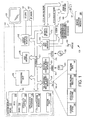
- FIG. 1 is a simplified schematic diagram illustrating an exemplary architecture of a computing device for carrying out an authentication protocol, in accordance with an embodiment of the invention.
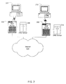
- Figure 2 is an exemplary network communication arrangement for authenticating the sender of a digital object, in accordance with an embodiment of the invention
- FIG. 3 illustrates an exemplary component architectures for use in authentication, in accordance with an embodiment of the invention
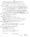
- Figure 4 illustrates a sample electronic mail message for use in sending and authenticating, in accordance with an embodiment of the invention
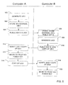
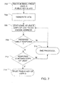
- Figure 5 depicts a flow diagram showing a protocol for authenticating the sender of an digital object, in accordance with an embodiment of the invention
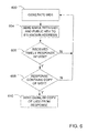
- Figure 6 is a flow diagram, illustrating a sender-employed method for use in authenticating a sender of a digital object, according to an example of the invention.
- Figure 7 is a flow diagram illustrating a receiver-employed method for use in authenticating a sender of a digital object, according to an embodiment of the invention.
- the invention may also be practiced in distributed computing environments where tasks are performed by remote processing devices that are linked through a communications network.
- program modules may be located in both local and remote memory storage devices.
- the term computer system may be used to refer to a system of computers such as may be found in a distributed computing environment.
- Figure 1 illustrates an example of a suitable computing system environment 100 on which the invention may be implemented.
- the computing system environment 100 is only one example of a suitable computing environment and is not intended to suggest any limitation as to the scope of use or functionality of the invention. Neither should the computing environment 100 be interpreter as having any dependency or requirement relating to any one or combination of components illustrated in the exemplary operating environment 100.
- one embodiment of the invention docs include each component illustrated in the exemplary operating environment 100, another more typical embodiment of the invention excludes non-essential components, for example, input/output devices other than those required for network communications.
- an exemplary system for implementing the invention includes a general purpose computing device in the form of a computer 110.
- Components of the computer 110 may include, but are not limited to, a processing unit 120, a system memory 130, and a system bus 121 that couples various system components including the system memory to the processing unit 120.
- the system bus 121 may be any of several types of bus structures including a memory bus or memory controller, a peripheral bus, and a local bus using any of a variety of bus architectures.
- such architectures include Industry Standard Architecture (ISA) bus, Micro Channel Architecture (MCA) bus, Enhanced ISA (EISA) bus, Video Electronics Standards Association (VESA) local bus, and Peripheral Component Interconnect (PCI) bus also known as Mezzanine bus.
- ISA Industry Standard Architecture
- MCA Micro Channel Architecture
- EISA Enhanced ISA
- VESA Video Electronics Standards Association
- PCI Peripheral Component Interconnect
- the computer 110 typically includes a variety of computer readable media.
- Computer readable media can be any available media that can be accessed by the computer 110 and includes both volatile and nonvolatile media, and removable and non-removable media.
- Computer readable media may comprise computer storage media and communication media.
- Computer storage media includes volatile and nonvolatile, removable and non-removable media implemented in any method or technology for storage of information such as computer readable instructions, data structures, program modules or other data.
- Computer storage media includes, but is not limited to, RAM, ROM, EEPROM, flash memory or other memory technology, CD-ROM, digital versatile disks (DVD) or other optical disk storage, magnetic cassettes, magnetic tape, magnetic disk storage or other magnetic storage devices, or any other medium which can be used to store the desired information and which can be accessed by the computer 110.
- Communication media typically embodies computer readable instructions, data structures, program modules or other data in a modulaled data signal such as a carrier wave or other transport mechanism and includes any information delivery media.
- modulate data signal means a signal that has one or more of its characteristics set or changed in such a manner as to encode information in the signal.
- communication media includes wired media such as a wired network or direct-wired connection, and wireless media such as acoustic, RF, infrared and other wireless media. Combinations of the any of the above should also be included within the scope of computer readable media.
- the system memory 130 includes computer storage media in the form of volatile and/or nonvolatile memory such as read only memory (ROM) 131 and random access memory (RAM) 132.
- ROM read only memory
- RAM random access memory
- BIOS basic input/output system
- RAM 132 typically contains data and/or program modules that are immediately accessible to and/or presently being operated on by processing unit 120.
- Figure 1 illustrates operating system 134, application programs 135, other program modules 136 and program data 137.
- the computer 110 may also include other removable non-removable, volatile/nonvolatile computer storage media.
- Figure 1 illustrates a hard disk drive 141 that reads from or writes to non-removable, nonvolatile magnetic media, a magnetic disk drive 151 that reads from or writes to a removable, nonvolatile magnetic disk 152, and an optical disk drive 155 that reads from or writes to a removable, nonvolatile optical disk 156 such as a CD ROM or other optical media.
- removable/non-removable, volatide/nonvolatile computer storage media that can be used in the exemplary operating environment include, but are not limited to, magnetic tape cassettes, flash memory cards, digital versatile disks, digital video tape, solid state RAM, solid state ROM, SmartCards, SecureDigital cards, SmartMedia cards, CompactFlash cards and the like.
- the hard disk drive 141 is typically connected to the system bus 121 through a non-removable memory interface such as interface 140, and magnetic disk drive 157 and optical disk drive 155 are typically connected to the system bus 121 by a removable memory interface, such as interface 150.
- hard disk drive 141 is illustrated has storing operating system 144, application programs 145, other program modules 146 and program data 147. Note that these components can either be the same as or different from operating system 134, application programs 135, other program modules 136, and program data 137. Operating system 144, application programs 145, other program modules 146, and program data 147 are given different numbers hereto illustrate that, at a minimum, they are different copies.
- a user may enter commands and information into the computer 110 through input devices such as a tablet, or electronic digitizer, 164, a microphone 163, a keyboard 162 and pointing device 161, commonly referred to as a mouse, trackball or touch pad.
- Other input devices may include a joystick, game pad, satellite dish, scanner, or the like.
- a monitor 191 or other type or display device is also connected to the system bus 121 via an interface, such as a video interface 190.
- the monitor 191 may also he integrated with a touch-screen panel or the like. Note that the monitor and/or touch screen panel can be physically coupled to a housing in which the computing device 110 is incorporated, such as in a tablet-type personal, computer, In addition, computers such as the computing device 110 may also include other peripheral output devices such as speakers 197 and printer 196, which may be connected through an output peripheral interface 194 or the like.
- the computer 110 may operate in a networked environment using logical connections to one or more remote computers, such as a remote computer 180.
- the remote computer 180 may be a personal computer, a server, a router, a network PC, a peer device or other common network node, and typically includes many or all of the elements described above relative to the computer 110, although only a memory storage device 181 has been illustrated in Figure 1 .
- the logical connections depicted in Figure 1 include a local area network (LAN) 117 and a wide area network (WAN) 173, but may also include other networks, Such networking environments are commonplace in offices, enterprise-wide computer networks, intranets and the Internet.
- the computer 110 may comprise the source machine from which data is being migrated
- the remote computer 180 may comprise the destination machine.
- source and destination machines need not be connected by a network or any other means, but instead, data may be migrated via any media capable of being written by the source platform and read by the destination platform or platforms.
- the computer 110 When used in a LAN networking environment, the computer 110 is connected to the LAN 171 through a network interface or adapter 170. Alternatively, the computer 110 contains a wireless LAN network interface operating on, for example, the 802.11b protocol, allowing the computer 110 to connect to the LAN 171 without a physical connection.
- the computer 110 When used in a WAN networking environment, the computer 110 typically includes a modem 172 or other means for establishing communications over the WAN 173, such as the Internet.
- the modem 172 which may be internal or external, may be connected to the system bus 121 via the user input interface 160 or other appropriate mechanism.
- the computer 110 contains a wireless WAN network interface operating over, for example, the General Packet Radio Service (GPRS), allowing the computer 110 to connect to the WAN 173 without a physical connection.
- GPRS General Packet Radio Service
- program modules depicted relative to the computer 110, or portions thereof, may be stored in the remote memory storage device.
- Figure 1 illustrates remote application programs 185 as residing on memory device 181. It will he appreciated that the network connections shown are exemplary and other means of establishing a communications link between the computers may be used.
- variations of the computer 110 may be incorporated into other exemplary systems for implementing the invention, such as cellular phones, personal digital assistants, and the like.
- a first computer 202 used by a user "A" who wishes to transmit his public encryption key to user "B” via email, communicates with a mail server 204.
- the computer 202 contains, for example, a mail application with which user "A” composes messages and transmits them to the mail server 204.
- the mail server 204 uses a known and accepted mail protocol, such as the Simple Mail Transport Protocol (SMTP) to transmit electronic messages.
- SMTP Simple Mail Transport Protocol
- a message created by user "A” typically contains an address for a recipient in the form of "userB@domain.com”.
- the characters to the right of the '@' symbol, "domain.com” in this example, comprise the domain name, which is a logical domain for a computer receiving mail for user "B".
- the mail server 204 obtains a corresponding physical address for the logical address by querying a Domain Name System (DNS) server 206.
- DNS Domain Name System
- the DNS server 206 belongs to a hierarchy of distributed DNS servers, which serves as mapping service between logical addresses and physical addresses.
- the physical address takes the form of an Internet Protocol (IP) address, which identifies a computer 208 on the Internet 210.
- IP Internet Protocol
- Embodiments of the invention establish a secure communications channel between the sending mail server 204 and the receiving mail server 212 by using Transport Layer Security (TLS), ensuring that communications between the two servers cannot be eavesdropped.
- TLS Transport Layer Security
- the mail server 204 sends the email message with the obtained physical address using the TCP/IP protocol, causing it to be routed over the Internet 210.
- the message reaches a computer 208 associated with the IP address that acts as a mail server for user "B".
- User "B” the intended recipient of the message, uses a computer 212 to obtain email messages intended for him.
- Computer 212 communicates with mail server 208 and receives the appropriate messages.
- the mail server 208 queries a DNS server 214 to obtain the physical address of the intended recipient.
- FIG. 3 illustrates a set of software components executing on the user computer 202 in accordance with an embodiment of the invention.
- the user interacts with a mail application program 302 to send and receive email messages.
- An exemplary mail application program is Outlook, by the MICROSOFT CORPORATION of Redmond, Washington.
- the mail application 302 sends and receives both text and binary files, such as executable programs, documents or other files.
- a single message sent or received by the mail application 302 can contain text, binary tiles, or both.
- Embodiments of the invention facilitate the exchange of public cryptographic keys, such as those used in the RSA cryptographic scheme. In such a scheme, a user mathematically creates two keys: a private key 304 and a public key 306.
- the user makes the public key 306 available to anyone, while he keeps the private key 304 a secret. Although anyone can encrypt a message using the public key 306, only a holder of the private key 304 is able to decrypt the encrypted message.
- the mathematical properties of the scheme also allow the user to digitally 'sign' messages by encrypting them with his private key 304.
- anyone holding the public key 306 can decrypt the message to verify it was written by the user.
- the exemplary RSA scheme is more fully described in U.S. Patent 4,405,829 .
- the user computer 202 in an embodiment of the invention, contains an encryption/decryption engine 308 for manipulating encrypting and decrypting operations involving the private key 304 and public key 306.
- Embodiments of the invention also contain a random number generator 310.
- the random number generator 310 preferably produces a string of bits such that it is practically infeasible to predict any bit of the sequence given any other bits of the sequence. Thus, it is not necessary that the sequence is truly random, but the sequence must appear random to a sufficient degree of unpredictability.
- Embodiments call functions such as the UuidCreate function provided by the Microsoft Developer Network, which use pseudo-random number generators employing algorithms to generate a globally unique identifier.
- Figure 4 shows a typical email message 400 with headers, as used in an embodiment of the invention.
- the format of an email message complies witch RFC 822.
- a sender claiming to have the address "john@uchicagox.edu” is sending a message containing a Microsoft Excel file 401 to a recipient at the address "arf@arfdomainx.com".
- Other attachments such as public-keys for cryptographic protocols, are alternatively attached.
- Several headers 402 at the top of the message contain routing information tracing the route of the message 400 from the sender to the recipient.
- the sender has indicated in a "From" header 404 that his name is "John Smith” and his address is "john@uchicagox.edu".
- the sender also affirms this is his address in the signature field 405 in the body of the message.
- other headers such as the "Received" header 406 and the "Return-Path” header 408 indicate the message is actually sent from a different address, "john@realaddress.org".
- the headers indicating the sender's address can be faked, or "spoofed” with varying degrees of difficulty.
- a savvy sender can spoof the return addresses to make it impossible to determine with certainty the sender's actual address.
- the recipient of a message does not allays have confidence that the message actually came from the purported sender.
- the message 400 also contains a "To" header 410.
- the "To" header 410 indicates where the message should be sent, in this case to "arf@arfdomainx.com”.
- the "To" header is difficult to spoof. That is, if a sender sends a message to a recipient addressed in the "To" field, there is a high degree of confidence that the message will reach the recipient, and not be redirected somewhere else instead.
- the method assumes that each user of the two computers has prior knowledge of the other user's email address.
- the first computer used by user A, generates a unique identifier, UID1, at step 502 using a random or pseudo-random number generator.
- UID1 is sufficiently large that it is difficult to guess. In practice, 128 bits suffice to ensure the identifier is unique.
- the first computer stores UID1, indexed by the email address for user B, at step 504.
- the first computer sends UID1, along with user A's public key, to the second computer by using the previously known email address of user B, at step 505.
- the second computer receives the message and stores a copy of UID1, user A's public key, and the email address listed in the "From" field of the message, at step 506.
- the second computer uses, by way of example, a random or pseudo-random number generator to create a unique identifier, UID2, at step 508.
- UID2 is preferably at least 128 bits in length.
- the second computer sends user B's public key, along with UID2 and a copy of UID1, to the first computer, at step 510. This message, however, is addressed using the previously known address for user A, disregarding any return email address in a "From" or "Reply To" field of the first message.
- the first computer receives the message from the second computer and verifies that the copy of UID1 is accurate, using the email address in the "From" field to index the locally stored UID1.
- User A then trusts that the public key received from user B is authentic (i.e., that it actually came from user B) at step 514.
- the first computer then sends a copy of UID2 back to user B, at step 516.
- the second computer receives the message and verifies that the copy of UID2 is accurate, using the email address in the "From" field to index the locally stored UID2, at step 518.
- User B then trusts that the public key received from user A is authentic (i.e., that it actually came from user A), at step 520.
- Figure 6 illustrates a method for using email to send a user's public key such that the recipient has confidence that the public key came from the user, in accordance with an example.
- the user first generates a unique identifier (UID1) at step 602 using, by way of example, a random or pseudo-random number generator.
- the unique identifier is sufficiently large that it is difficult to guess. In practice, 128 bits suffice to ensure the identifier is unique.
- the user sends an email message containing his public key and UID1 to a previously known address for the recipient.
- the user monitors for a timely response that contains a second unique identifier, UID2, at step 606.
- a timespan for monitoring at step 606 is configurable by the user.
- the user begins again at step 602. Otherwise, the user checks that the response contains a copy of UID1 at step 608. If the copy of UID1 is incorrect, the user begins again at step 602. Otherwise, the user sends an email containing a copy of UID2 to the recipient at step 610.
- Figure 7 illustrates a method for using email to receive a sender's public key such that the user has confidence that the public key came from the sender, in accordance with an embodiment of the invention.
- the user receives an email at step 702 containing a public key and a unique identifier, UID1. Although the message contains a "From" field identifying a sender, the user is not confident that the message actually came from the purported sender.
- the user generates a unique identifier UID2 at step 704 using a random or pseudo-random number generator. He sends an email message containing UID2 and a copy of UID1 to the purported sender, but by using a previously known address for the sender, at step 706. The user monitors for a timely response at step 708.
- the amount of time used for monitoring at step 708 is configurable by the user. If a timely response is not received, the user ends the protocol at step 710. Alternatively, if a timely response is not received, the user rescnds the message containing UID2 and a copy of UID1 at step 706. Otherwise, the user checks that the response contains a copy of UID2 at step 712. If the copy of UID2 is incorrect, the protocol ends at step 710. Otherwise, the user is convinced that the public key came from the purported sender, and begins to trust the key at step 714.
- Embodiments of the invention further allow the exchange of digital objects other than public keys.
- a first user can use an embodiment of the invention to send a document to a second user so that the second user is convinced that it was, indeed, the first user who sent the document.
- embodiments of the invention enable authentication of parties simultaneously with the transmission of digital objects by "bootstrapping" the objects to email messages. In the instance when the digital object is a public key, the authenticated key can be subsequently used for secure communications between the parties.
Description
- This invention pertains generally to the field of information security and more specifically to authentication protocols.
- A common form of communications between computers connected to the Internet follows a paradigm known in the industry as client-server. For example, existing servers are email servers, web servers, tile servers, online banking servers, etc. Clients include home personal computers, office personal computers, laptop computers, hand-held devices, wireless digital telephones, etc. The various client devices connect and interact with the various server devices. In this model the different servers employ their own ways of authenticating and authorizing the client devices that connect with them. For example, some email servers issue and use pre-registered identities to authenticate and authorize. Some banking organizations use their own member identification and password databases to do the authentication and authorization. So a given client device, say a personal computer at home, needs to conform to the differing authentication methods enforced by the different servers with which it connects and interacts. In the client-server model, the broad problem of how two interacting computers "recognize" one another currently is solved by making the server computer enforce its preferences unilaterally on the client computer.
- Although the above-described model works well for client-server interaction, it becomes impractical for interactions between the various client machines themselves. The industry terminology for such interaction between various client devices is called peer-to-peer (P2P) communications. In this case, neither client computer can force its authentication preferences on the other. For example, consider the desire for a first user, Alice, to share and exchange videos and pictures from her personal computer with a second user, Bob, who also has a personal computer. Bob may wish to authenticate Alice, in order to be confident that the videos and pictures are indeed being sent by her, rather than being sent by an imposter.
- Additionally, Alice may wish to transmit the videos and pictures securely using an encryption technique such as RSA, so that an eavesdropper cannot view the videos or pictures. RSA is a public-key cryptography technique whereby anyone can encrypt data for a given user with the user's public-key, but only the user can decrypt the data by using the corresponding private-key. Thus, Alice and Bob need to first exchange their respective public-keys in order to establish the secure channel per the RSA algorithm. Exchanging public-keys is not a trivial task. Charlie, a malicious hacker, could try to "sit in the middle" of the key exchange communication. Charlie sends his own public-key to Alice, but pretending to be Bob; he sends his own public-key to Bob, but pretending to be Alice. Given that this initial key exchange communication is itself not secure, there is no simple way for Alice and Bob to realize that Charlie is "in the middle", If they fall for Charlie's ploy and start communicating using his key, he can act as the middle-man and pass all the communications between Alice and Bob, but be able to eavesdrop on all the content being passed back and forth. And of course he can make this even worse by changing the passed content as well.
- Thus, Alice and Bob have a problem of how they can confidently "bootstrap" the exchange of public keys onto their communications session. More generally, the bootstrapping problem in a P2P setting involves exchanging any sort of public data or digital object such that the recipient is confident it came from the purported sender.
From XP-00234973 the fixing of a problem in the Helsinki protocol is known. - The problem is solved by the method of claim 1 and the medium of claim 9. Preferred embodiments are disclosed in the dependent claims.
- Embodiments of the invention use the popular Simple Mail Transport Protocol (SMTP) for email exchange, to solve the bootstrapping problem of computer identities, for P2P communication. Typically this is a prerequisite for using algorithms like RSA that establish a logically secure communication channel over a physically insecure network. With the RSA algorithm the bootstrapping problem is one of how to have two peer computers exchange their mutual Public Keys without third party mediation (like Certificate Authorities). With other algorithms or technologies, the data involved in such a bootstrapping problem may be different, but the underlying problem of exchanging some public data with the confidence that there is no spoofing is the same.
- Embodiments of the invention use existing electronic mail protocols, such as SMTP, to authenticate the exchange of public information. If the electronic mail protocols are strong, in that sending an email message to a given address results in the message reaching that address with a high degree of confidence, then the exchange of public information performed in accordance with embodiments of the invention is authenticated.
- In one example a method is provided for authenticating the sender of a digital object, comprising generating a first unique identifier (UID), transmitting to a previously known address, via an electronic mail protocol, a first message comprising the first UID, receiving, via the electronic mail protocol, a second message comprising a second UID and a copy of the first UID, and transmitting to the previously known address, via the electronic mail protocol, a third message comprising a copy of the second UID, wherein at least one of the messages transmitted to the previously known address further comprises the digital object. In one example of the invention, the digital object is a public key for a cryptographic system. In example of the invention, the electronic mail protocol comprises a mail server operating the Simple Mail Transport Protocol (SMTP).
- In another example, a computer-readable medium including computer-executable instructions is provided for facilitating authenticating a sender of a digital object, computer-executable instructions executing the steps of generating a first unique identifier (UID), transmitting to a previously known address, via an electronic mail protocol, a first message comprising the first UID, receiving, via the electronic mail protocol, a second message comprising a second UID and a copy of the first UID, and transmitting to the previously known address, via the electronic mail protocol, a third message comprising a copy of the second UID, wherein at least one of the messages transmitted to the previously known address further comprises the digital object. In embodiments of the invention, the digital object is a public key for a cryptographic system. In embodiments of the invention, the electronic mail protocol comprises a mail server operating the Simple Mail Transport Protocol (SMTP).
- The present example, viewed another way, comprises an apparatus is provided for authenticating the sender of a digital object, comprising a random number generator generation a first unique identifier (UID), a network interface transmitting to a previously known address, via an electronic mail protocol, a first message comprising the first UID, the network interface receiving, via the electronic mail protocol, a second message comprising a second UID and a copy of the first UID, and the network interface transmitting to the previously known address, via the electronic mail protocol, a third message comprising a copy of the second UID, wherein at least one of the messages transmitted to the previously known address further comprises the digital object.
- While the appended claims set forth the features of the present invention with particularity, the invention and its advantages are best understood from the following detailed description taken in conjunction with the accompanying drawings, of which:
-
Figure 1 is a simplified schematic diagram illustrating an exemplary architecture of a computing device for carrying out an authentication protocol, in accordance with an embodiment of the invention. -
Figure 2 is an exemplary network communication arrangement for authenticating the sender of a digital object, in accordance with an embodiment of the invention; -
Figure 3 illustrates an exemplary component architectures for use in authentication, in accordance with an embodiment of the invention; -
Figure 4 illustrates a sample electronic mail message for use in sending and authenticating, in accordance with an embodiment of the invention; -
Figure 5 depicts a flow diagram showing a protocol for authenticating the sender of an digital object, in accordance with an embodiment of the invention; -
Figure 6 is a flow diagram, illustrating a sender-employed method for use in authenticating a sender of a digital object, according to an example of the invention; and -
Figure 7 is a flow diagram illustrating a receiver-employed method for use in authenticating a sender of a digital object, according to an embodiment of the invention. - The methods and systems supporting secure key exchanges using email will now be described with respect to a number of embodiments; however, the methods and systems of the invention are not limited to the illustrated embodiments. Moreover, the skilled artisan will readily appreciate that the methods and systems described herein are merely exemplary and that variations can be made without departing from the spirit and scope of the invention.
- The invention will be more completely understood through the following detailed description, which should be read in conjunction with the attached drawings. In this description, like numbers refer to similar elements within various embodiments of the present invention. The invention is illustrated as being implemented in a suitable computing environment. Although not required, the invention will be described in the general context of computer-executable instructions, such as procedures, being executed by a personal computer. Generally, procedures include program modules, routines, functions, programs, objects, components, data structures, etc. that perform particular tasks or implement particular abstract data types. Moreover, those skilled in the art will appreciate that the invention may be practiced with other computer system configurations, including hand-held devices, multiprocessor systems, microprocessor based or programmable consumer electronics, network PCs, minicomputers, mainframe computers, and the like. The invention may also be practiced in distributed computing environments where tasks are performed by remote processing devices that are linked through a communications network. In a distributed computing environment, program modules may be located in both local and remote memory storage devices. The term computer system may be used to refer to a system of computers such as may be found in a distributed computing environment.
-
Figure 1 illustrates an example of a suitablecomputing system environment 100 on which the invention may be implemented. Thecomputing system environment 100 is only one example of a suitable computing environment and is not intended to suggest any limitation as to the scope of use or functionality of the invention. Neither should thecomputing environment 100 be interpreter as having any dependency or requirement relating to any one or combination of components illustrated in theexemplary operating environment 100. Although one embodiment of the invention docs include each component illustrated in theexemplary operating environment 100, another more typical embodiment of the invention excludes non-essential components, for example, input/output devices other than those required for network communications. - With reference to
Figure 1 , an exemplary system for implementing the invention includes a general purpose computing device in the form of acomputer 110. Components of thecomputer 110 may include, but are not limited to, aprocessing unit 120, asystem memory 130, and asystem bus 121 that couples various system components including the system memory to theprocessing unit 120. Thesystem bus 121 may be any of several types of bus structures including a memory bus or memory controller, a peripheral bus, and a local bus using any of a variety of bus architectures. By way of example, and not limitation, such architectures include Industry Standard Architecture (ISA) bus, Micro Channel Architecture (MCA) bus, Enhanced ISA (EISA) bus, Video Electronics Standards Association (VESA) local bus, and Peripheral Component Interconnect (PCI) bus also known as Mezzanine bus. - The
computer 110 typically includes a variety of computer readable media. Computer readable media can be any available media that can be accessed by thecomputer 110 and includes both volatile and nonvolatile media, and removable and non-removable media. By way of example, and not limitation, computer readable media may comprise computer storage media and communication media. Computer storage media includes volatile and nonvolatile, removable and non-removable media implemented in any method or technology for storage of information such as computer readable instructions, data structures, program modules or other data. Computer storage media includes, but is not limited to, RAM, ROM, EEPROM, flash memory or other memory technology, CD-ROM, digital versatile disks (DVD) or other optical disk storage, magnetic cassettes, magnetic tape, magnetic disk storage or other magnetic storage devices, or any other medium which can be used to store the desired information and which can be accessed by thecomputer 110. Communication media typically embodies computer readable instructions, data structures, program modules or other data in a modulaled data signal such as a carrier wave or other transport mechanism and includes any information delivery media. The term "modulate data signal" means a signal that has one or more of its characteristics set or changed in such a manner as to encode information in the signal. By way of example, and not limitation, communication media includes wired media such as a wired network or direct-wired connection, and wireless media such as acoustic, RF, infrared and other wireless media. Combinations of the any of the above should also be included within the scope of computer readable media. - The
system memory 130 includes computer storage media in the form of volatile and/or nonvolatile memory such as read only memory (ROM) 131 and random access memory (RAM) 132. A basic input/output system 133 (BIOS), containing the basic routines that help to transfer information between elements withincomputer 110, such as during start-up, is typically stored inROM 131.RAM 132 typically contains data and/or program modules that are immediately accessible to and/or presently being operated on by processingunit 120. By way of example, and not limitation,Figure 1 illustratesoperating system 134, application programs 135, other program modules 136 andprogram data 137. - The
computer 110 may also include other removable non-removable, volatile/nonvolatile computer storage media. By way of example only,Figure 1 illustrates ahard disk drive 141 that reads from or writes to non-removable, nonvolatile magnetic media, amagnetic disk drive 151 that reads from or writes to a removable, nonvolatilemagnetic disk 152, and anoptical disk drive 155 that reads from or writes to a removable, nonvolatileoptical disk 156 such as a CD ROM or other optical media. Other removable/non-removable, volatide/nonvolatile computer storage media that can be used in the exemplary operating environment include, but are not limited to, magnetic tape cassettes, flash memory cards, digital versatile disks, digital video tape, solid state RAM, solid state ROM, SmartCards, SecureDigital cards, SmartMedia cards, CompactFlash cards and the like. Thehard disk drive 141 is typically connected to thesystem bus 121 through a non-removable memory interface such asinterface 140, and magnetic disk drive 157 andoptical disk drive 155 are typically connected to thesystem bus 121 by a removable memory interface, such asinterface 150. - The drives and their associated computer storage media, discussed above and illustrated in
Figure 1 , provide storage of computer readable instructions, data structures, program modules and other data for thecomputer 110. InFigure 1 , for example,hard disk drive 141 is illustrated has storingoperating system 144,application programs 145,other program modules 146 andprogram data 147. Note that these components can either be the same as or different fromoperating system 134, application programs 135, other program modules 136, andprogram data 137.Operating system 144,application programs 145,other program modules 146, andprogram data 147 are given different numbers hereto illustrate that, at a minimum, they are different copies. A user may enter commands and information into thecomputer 110 through input devices such as a tablet, or electronic digitizer, 164, a microphone 163, akeyboard 162 andpointing device 161, commonly referred to as a mouse, trackball or touch pad. Other input devices (not shown) may include a joystick, game pad, satellite dish, scanner, or the like. These and other input devices are often connected to theprocessing unit 120 through auser input interface 160 that is coupled to the system bus, but may be connected by other interface and bus structures, such as a parallel port, game port or a universal serial bus (USB). Amonitor 191 or other type or display device is also connected to thesystem bus 121 via an interface, such as avideo interface 190. Themonitor 191 may also he integrated with a touch-screen panel or the like. Note that the monitor and/or touch screen panel can be physically coupled to a housing in which thecomputing device 110 is incorporated, such as in a tablet-type personal, computer, In addition, computers such as thecomputing device 110 may also include other peripheral output devices such asspeakers 197 andprinter 196, which may be connected through an output peripheral interface 194 or the like. - The
computer 110 may operate in a networked environment using logical connections to one or more remote computers, such as aremote computer 180. Theremote computer 180 may be a personal computer, a server, a router, a network PC, a peer device or other common network node, and typically includes many or all of the elements described above relative to thecomputer 110, although only amemory storage device 181 has been illustrated inFigure 1 . The logical connections depicted inFigure 1 include a local area network (LAN) 117 and a wide area network (WAN) 173, but may also include other networks, Such networking environments are commonplace in offices, enterprise-wide computer networks, intranets and the Internet. For example, in the present invention, thecomputer 110 may comprise the source machine from which data is being migrated, and theremote computer 180 may comprise the destination machine. Note however that source and destination machines need not be connected by a network or any other means, but instead, data may be migrated via any media capable of being written by the source platform and read by the destination platform or platforms. - When used in a LAN networking environment, the
computer 110 is connected to theLAN 171 through a network interface oradapter 170. Alternatively, thecomputer 110 contains a wireless LAN network interface operating on, for example, the 802.11b protocol, allowing thecomputer 110 to connect to theLAN 171 without a physical connection. When used in a WAN networking environment, thecomputer 110 typically includes amodem 172 or other means for establishing communications over theWAN 173, such as the Internet. Themodem 172, which may be internal or external, may be connected to thesystem bus 121 via theuser input interface 160 or other appropriate mechanism. Alternatively, thecomputer 110 contains a wireless WAN network interface operating over, for example, the General Packet Radio Service (GPRS), allowing thecomputer 110 to connect to theWAN 173 without a physical connection. In a networked environment, program modules depicted relative to thecomputer 110, or portions thereof, may be stored in the remote memory storage device. By way of example, and not limitation,Figure 1 illustratesremote application programs 185 as residing onmemory device 181. It will he appreciated that the network connections shown are exemplary and other means of establishing a communications link between the computers may be used. Additionally, variations of thecomputer 110 may be incorporated into other exemplary systems for implementing the invention, such as cellular phones, personal digital assistants, and the like. - The invention is potentially incorporated into computing devices/machines used in a variety of networking environments. Turning to
Figure 2 , a simple example of a networking environment is depicted wherein the invention can be exploited. Afirst computer 202, used by a user "A" who wishes to transmit his public encryption key to user "B" via email, communicates with amail server 204. Thecomputer 202 contains, for example, a mail application with which user "A" composes messages and transmits them to themail server 204. Themail server 204 uses a known and accepted mail protocol, such as the Simple Mail Transport Protocol (SMTP) to transmit electronic messages. A message created by user "A" typically contains an address for a recipient in the form of "userB@domain.com". The characters to the right of the '@' symbol, "domain.com" in this example, comprise the domain name, which is a logical domain for a computer receiving mail for user "B". Themail server 204 obtains a corresponding physical address for the logical address by querying a Domain Name System (DNS)server 206. TheDNS server 206 belongs to a hierarchy of distributed DNS servers, which serves as mapping service between logical addresses and physical addresses. The physical address takes the form of an Internet Protocol (IP) address, which identifies acomputer 208 on theInternet 210. Embodiments of the invention establish a secure communications channel between the sendingmail server 204 and the receivingmail server 212 by using Transport Layer Security (TLS), ensuring that communications between the two servers cannot be eavesdropped. Themail server 204 sends the email message with the obtained physical address using the TCP/IP protocol, causing it to be routed over theInternet 210. The message reaches acomputer 208 associated with the IP address that acts as a mail server for user "B". User "B", the intended recipient of the message, uses acomputer 212 to obtain email messages intended for him.Computer 212 communicates withmail server 208 and receives the appropriate messages. Similarly, when user "B" attempts to send an email message over theInternet 210, themail server 208 queries aDNS server 214 to obtain the physical address of the intended recipient. -
Figure 3 illustrates a set of software components executing on theuser computer 202 in accordance with an embodiment of the invention. The user interacts with amail application program 302 to send and receive email messages. An exemplary mail application program is Outlook, by the MICROSOFT CORPORATION of Redmond, Washington. Themail application 302 sends and receives both text and binary files, such as executable programs, documents or other files. A single message sent or received by themail application 302 can contain text, binary tiles, or both. Embodiments of the invention facilitate the exchange of public cryptographic keys, such as those used in the RSA cryptographic scheme. In such a scheme, a user mathematically creates two keys: aprivate key 304 and apublic key 306. The user makes thepublic key 306 available to anyone, while he keeps the private key 304 a secret. Although anyone can encrypt a message using thepublic key 306, only a holder of theprivate key 304 is able to decrypt the encrypted message. The mathematical properties of the scheme also allow the user to digitally 'sign' messages by encrypting them with hisprivate key 304. Anyone holding thepublic key 306 can decrypt the message to verify it was written by the user. The exemplary RSA scheme is more fully described inU.S. Patent 4,405,829 . Theuser computer 202, in an embodiment of the invention, contains an encryption/decryption engine 308 for manipulating encrypting and decrypting operations involving theprivate key 304 andpublic key 306. - Embodiments of the invention also contain a
random number generator 310. Therandom number generator 310 preferably produces a string of bits such that it is practically infeasible to predict any bit of the sequence given any other bits of the sequence. Thus, it is not necessary that the sequence is truly random, but the sequence must appear random to a sufficient degree of unpredictability. Embodiments call functions such as the UuidCreate function provided by the Microsoft Developer Network, which use pseudo-random number generators employing algorithms to generate a globally unique identifier. -
Figure 4 shows atypical email message 400 with headers, as used in an embodiment of the invention. In embodiments of the invention, the format of an email message complies witch RFC 822. In theexample message 400, a sender claiming to have the address "john@uchicagox.edu" is sending a message containing a Microsoft Excel file 401 to a recipient at the address "arf@arfdomainx.com". Other attachments, such as public-keys for cryptographic protocols, are alternatively attached.Several headers 402 at the top of the message contain routing information tracing the route of themessage 400 from the sender to the recipient. The sender has indicated in a "From"header 404 that his name is "John Smith" and his address is "john@uchicagox.edu". The sender also affirms this is his address in thesignature field 405 in the body of the message. However, other headers, such as the "Received"header 406 and the "Return-Path"header 408 indicate the message is actually sent from a different address, "john@realaddress.org". In fact, the headers indicating the sender's address can be faked, or "spoofed" with varying degrees of difficulty. With some messages, a savvy sender can spoof the return addresses to make it impossible to determine with certainty the sender's actual address. In other words, the recipient of a message does not allays have confidence that the message actually came from the purported sender. - The
message 400 also contains a "To"header 410. The "To"header 410 indicates where the message should be sent, in this case to "arf@arfdomainx.com". Unlike the "From"headers - Turning to
Figure 5 , a method is described whereby two users, A and B, of networked computers exchange public keys such that each trusts the authenticity of the other, in accordance with an embodiment of the invention. The method assumes that each user of the two computers has prior knowledge of the other user's email address. The first computer, used by user A, generates a unique identifier, UID1, atstep 502 using a random or pseudo-random number generator. The unique identifier is sufficiently large that it is difficult to guess. In practice, 128 bits suffice to ensure the identifier is unique. The first computer stores UID1, indexed by the email address for user B, atstep 504. The first computer sends UID1, along with user A's public key, to the second computer by using the previously known email address of user B, atstep 505. - The second computer receives the message and stores a copy of UID1, user A's public key, and the email address listed in the "From" field of the message, at
step 506. The second computer then uses, by way of example, a random or pseudo-random number generator to create a unique identifier, UID2, atstep 508. UID2 is preferably at least 128 bits in length. The second computer sends user B's public key, along with UID2 and a copy of UID1, to the first computer, atstep 510. This message, however, is addressed using the previously known address for user A, disregarding any return email address in a "From" or "Reply To" field of the first message. - At
step 512, the first computer receives the message from the second computer and verifies that the copy of UID1 is accurate, using the email address in the "From" field to index the locally stored UID1. User A then trusts that the public key received from user B is authentic (i.e., that it actually came from user B) atstep 514. The first computer then sends a copy of UID2 back to user B, atstep 516. - The second computer receives the message and verifies that the copy of UID2 is accurate, using the email address in the "From" field to index the locally stored UID2, at
step 518. User B then trusts that the public key received from user A is authentic (i.e., that it actually came from user A), atstep 520. -
Figure 6 illustrates a method for using email to send a user's public key such that the recipient has confidence that the public key came from the user, in accordance with an example. The user first generates a unique identifier (UID1) atstep 602 using, by way of example, a random or pseudo-random number generator. The unique identifier is sufficiently large that it is difficult to guess. In practice, 128 bits suffice to ensure the identifier is unique. Atstep 604, the user sends an email message containing his public key and UID1 to a previously known address for the recipient. The user monitors for a timely response that contains a second unique identifier, UID2, atstep 606. In some examples, a timespan for monitoring atstep 606 is configurable by the user. If a timely response is not received, the user begins again atstep 602. Otherwise, the user checks that the response contains a copy of UID1 atstep 608. If the copy of UID1 is incorrect, the user begins again atstep 602. Otherwise, the user sends an email containing a copy of UID2 to the recipient atstep 610. -
Figure 7 illustrates a method for using email to receive a sender's public key such that the user has confidence that the public key came from the sender, in accordance with an embodiment of the invention. The user receives an email atstep 702 containing a public key and a unique identifier, UID1. Although the message contains a "From" field identifying a sender, the user is not confident that the message actually came from the purported sender. The user generates a unique identifier UID2 atstep 704 using a random or pseudo-random number generator. He sends an email message containing UID2 and a copy of UID1 to the purported sender, but by using a previously known address for the sender, atstep 706. The user monitors for a timely response atstep 708. In some embodiments, the amount of time used for monitoring atstep 708 is configurable by the user. If a timely response is not received, the user ends the protocol atstep 710. Alternatively, if a timely response is not received, the user rescnds the message containing UID2 and a copy of UID1 atstep 706. Otherwise, the user checks that the response contains a copy of UID2 atstep 712. If the copy of UID2 is incorrect, the protocol ends atstep 710. Otherwise, the user is convinced that the public key came from the purported sender, and begins to trust the key atstep 714. - Embodiments of the invention further allow the exchange of digital objects other than public keys. For example, a first user can use an embodiment of the invention to send a document to a second user so that the second user is convinced that it was, indeed, the first user who sent the document. More generally, embodiments of the invention enable authentication of parties simultaneously with the transmission of digital objects by "bootstrapping" the objects to email messages. In the instance when the digital object is a public key, the authenticated key can be subsequently used for secure communications between the parties.
- In view of the many possible embodiments to which the principles of the present invention may be applied, it should be recognized that the embodiments described herein with respect to the drawing figures are meant to be illustrative only and should not be taken as limiting the scope of the invention. For example, those of skill in the art will recognize that the illustrated embodiments can he modified in arrangement and detail. Although the invention is described in terms of software modules or components, those skilled in the art will recognize that such may be equivalently replaced by hardware components. Therefore, the invention as described herein contemplates all such embodiments as may come within the scope of the following claims and equivalents thereof.
Claims (9)
- A method for authenticating the sender of a digital object, comprising:receiving, via an electronic mail protocol, a first email message from a purported sender comprising a first unique identifier;generating (508) a second unique identifier;transmitting to a previously known email address of the purported sender of the first message by disregarding any return email address in a from field or reply to field of the first email message, via the electronic mail protocol, a second email message comprising the second unique identifier and a copy of the first unique identifier;receiving, via the electronic mail protocol, a third email message comprising a copy of the second unique identifier; andverifying (518) that the received copy of the second unique identifier is accurate;wherein at least one of the messages received further comprises the digital object.
- The method of claim 1 wherein the first message further comprises the digital object.
- The method of claim 1 wherein the third message further comprises the digital object.
- The method of claim 1 wherein the digital object is a public key for a cryptographic system.
- The method of claim 4 wherein the second electronic mail message further comprises a second public key for a cryptographic system.
- The method of claim 1 wherein the electronic mail protocol comprises a mail server operating the Simple Mail Transport Protocol, SMTP.
- The method of claim 1 wherein at least a portion of the electronic mail protocol operates securely using the Transport Layer Security, TLS, protocol.
- The method of claim 1 wherein the first unique identifier contains at least 128 bits.
- A computer-readable medium including computer-executable instructions for use in authenticating a sender of a digital object, computer-executable instructions which when executed by a computer cause the computer to perform each of Jan, 12. 2012 the steps of the method of any of claims 1 to 8.
Applications Claiming Priority (2)
| Application Number | Priority Date | Filing Date | Title |
|---|---|---|---|
| US816975 | 2004-04-02 | ||
| US10/816,975 US7721093B2 (en) | 2004-04-02 | 2004-04-02 | Authenticated exchange of public information using electronic mail |
Publications (3)
| Publication Number | Publication Date |
|---|---|
| EP1583319A2 EP1583319A2 (en) | 2005-10-05 |
| EP1583319A3 EP1583319A3 (en) | 2005-10-19 |
| EP1583319B1 true EP1583319B1 (en) | 2012-08-01 |
Family
ID=34887773
Family Applications (1)
| Application Number | Title | Priority Date | Filing Date |
|---|---|---|---|
| EP05102476A Not-in-force EP1583319B1 (en) | 2004-04-02 | 2005-03-30 | Authenticated exchange of public information using electronic mail |
Country Status (5)
| Country | Link |
|---|---|
| US (1) | US7721093B2 (en) |
| EP (1) | EP1583319B1 (en) |
| JP (1) | JP2005295509A (en) |
| KR (1) | KR101149958B1 (en) |
| CN (1) | CN1677975A (en) |
Families Citing this family (24)
| Publication number | Priority date | Publication date | Assignee | Title |
|---|---|---|---|---|
| US8417949B2 (en) * | 2005-10-31 | 2013-04-09 | Microsoft Corporation | Total exchange session security |
| US9002018B2 (en) * | 2006-05-09 | 2015-04-07 | Sync Up Technologies Corporation | Encryption key exchange system and method |
| JP4855147B2 (en) * | 2006-05-30 | 2012-01-18 | 株式会社Into | Client device, mail system, program, and recording medium |
| FR2907292A1 (en) * | 2006-10-16 | 2008-04-18 | France Telecom | MESSAGE CONTROL TO BE TRANSMITTED FROM A TRANSMITTER DOMAIN TO A RECEIVER DOMAIN |
| US20080137859A1 (en) * | 2006-12-06 | 2008-06-12 | Ramanathan Jagadeesan | Public key passing |
| US8769284B2 (en) * | 2006-12-29 | 2014-07-01 | Nokia Corporation | Securing communication |
| CN101247357B (en) * | 2007-02-16 | 2011-06-15 | 国际商业机器公司 | Method and system for improving E-mail discussion efficiency at E-mail client terminal |
| US8950001B2 (en) * | 2007-08-01 | 2015-02-03 | Avaya Inc. | Continual peer authentication |
| US8646039B2 (en) * | 2007-08-01 | 2014-02-04 | Avaya Inc. | Automated peer authentication |
| US8170957B2 (en) * | 2007-08-08 | 2012-05-01 | Sinart Points Technology, Inc. | System and method for managing digital interactions |
| US9325528B2 (en) | 2008-03-20 | 2016-04-26 | Iconix, Inc. | System and method for securely performing multiple stage email processing with embedded codes |
| US20110238498A1 (en) * | 2010-03-29 | 2011-09-29 | Microsoft Corporation | Service stage for subscription management |
| US8707420B2 (en) * | 2010-05-21 | 2014-04-22 | Microsoft Corporation | Trusted e-mail communication in a multi-tenant environment |
| US9542203B2 (en) | 2010-12-06 | 2017-01-10 | Microsoft Technology Licensing, Llc | Universal dock for context sensitive computing device |
| US8923770B2 (en) | 2010-12-09 | 2014-12-30 | Microsoft Corporation | Cognitive use of multiple regulatory domains |
| US8792429B2 (en) | 2010-12-14 | 2014-07-29 | Microsoft Corporation | Direct connection with side channel control |
| US9294545B2 (en) | 2010-12-16 | 2016-03-22 | Microsoft Technology Licensing, Llc | Fast join of peer to peer group with power saving mode |
| US8948382B2 (en) | 2010-12-16 | 2015-02-03 | Microsoft Corporation | Secure protocol for peer-to-peer network |
| US8971841B2 (en) | 2010-12-17 | 2015-03-03 | Microsoft Corporation | Operating system supporting cost aware applications |
| US10616177B2 (en) | 2015-03-31 | 2020-04-07 | Willie L. Donaldson | Secure dynamic address resolution and communication system, method, and device |
| WO2016160977A1 (en) * | 2015-03-31 | 2016-10-06 | Donaldson Willie L | Secure dynamic address resolution and communication system, method, and device |
| US10110552B2 (en) * | 2015-03-31 | 2018-10-23 | Willie L. Donaldson | Secure dynamic address resolution and communication system, method, and device |
| JP2020509625A (en) * | 2017-03-07 | 2020-03-26 | ヒューレット−パッカード デベロップメント カンパニー エル.ピー.Hewlett‐Packard Development Company, L.P. | Data message authentication based on random numbers |
| WO2020220034A1 (en) * | 2019-04-26 | 2020-10-29 | Csub Auxiliary For Sponsored Programs Administration | Reconfigurable security hardware and methods for internet of things (iot) systems |
Family Cites Families (11)
| Publication number | Priority date | Publication date | Assignee | Title |
|---|---|---|---|---|
| US4405829A (en) | 1977-12-14 | 1983-09-20 | Massachusetts Institute Of Technology | Cryptographic communications system and method |
| JP3009876B2 (en) * | 1997-08-12 | 2000-02-14 | 日本電信電話株式会社 | Packet transfer method and base station used in the method |
| US6351536B1 (en) | 1997-10-01 | 2002-02-26 | Minoru Sasaki | Encryption network system and method |
| US6684332B1 (en) | 1998-06-10 | 2004-01-27 | International Business Machines Corporation | Method and system for the exchange of digitally signed objects over an insecure network |
| US6209093B1 (en) | 1998-06-23 | 2001-03-27 | Microsoft Corporation | Technique for producing a privately authenticatable product copy indicia and for authenticating such an indicia |
| JP2001148715A (en) * | 1999-11-19 | 2001-05-29 | Mitsubishi Electric Corp | Network system and terminal device |
| GB2357229B (en) * | 1999-12-08 | 2004-03-17 | Hewlett Packard Co | Security protocol |
| US7024690B1 (en) * | 2000-04-28 | 2006-04-04 | 3Com Corporation | Protected mutual authentication over an unsecured wireless communication channel |
| US7127613B2 (en) * | 2002-02-25 | 2006-10-24 | Sun Microsystems, Inc. | Secured peer-to-peer network data exchange |
| EP1488330B1 (en) * | 2002-03-15 | 2014-05-07 | Shinkuro, Inc. | Method for forming groups |
| US7386878B2 (en) | 2002-08-14 | 2008-06-10 | Microsoft Corporation | Authenticating peer-to-peer connections |
-
2004
- 2004-04-02 US US10/816,975 patent/US7721093B2/en not_active Expired - Fee Related
-
2005
- 2005-02-15 JP JP2005038373A patent/JP2005295509A/en active Pending
- 2005-02-24 KR KR1020050015294A patent/KR101149958B1/en not_active IP Right Cessation
- 2005-03-02 CN CNA2005100531764A patent/CN1677975A/en active Pending
- 2005-03-30 EP EP05102476A patent/EP1583319B1/en not_active Not-in-force
Also Published As
| Publication number | Publication date |
|---|---|
| US7721093B2 (en) | 2010-05-18 |
| KR20060043176A (en) | 2006-05-15 |
| EP1583319A2 (en) | 2005-10-05 |
| CN1677975A (en) | 2005-10-05 |
| EP1583319A3 (en) | 2005-10-19 |
| JP2005295509A (en) | 2005-10-20 |
| US20050223226A1 (en) | 2005-10-06 |
| KR101149958B1 (en) | 2012-06-01 |
Similar Documents
| Publication | Publication Date | Title |
|---|---|---|
| EP1583319B1 (en) | Authenticated exchange of public information using electronic mail | |
| US7366905B2 (en) | Method and system for user generated keys and certificates | |
| US7039713B1 (en) | System and method of user authentication for network communication through a policy agent | |
| US8489877B2 (en) | System, method and computer product for sending encrypted messages to recipients where the sender does not possess the credentials of the recipient | |
| EP1782213B1 (en) | Secure messaging system with derived keys | |
| US7278017B2 (en) | Method and device for secure wireless transmission of information | |
| EP1673890B1 (en) | Identity-based-encryption system with district policy information | |
| US8340283B2 (en) | Method and system for a PKI-based delegation process | |
| US8656177B2 (en) | Identity-based-encryption system | |
| US6684332B1 (en) | Method and system for the exchange of digitally signed objects over an insecure network | |
| EP1701494B1 (en) | Determining a correspondent server having compatible secure e-mail technology | |
| JPH09219701A (en) | Method and device for retrieving identity recognizing identification | |
| WO2001095559A1 (en) | Method and device for secure wireless transmission of information | |
| JP2006514478A (en) | Online / offline decoding system | |
| US20070288746A1 (en) | Method of providing key containers | |
| EP3346659B1 (en) | Communication method for electronic communication system in open environment | |
| Setapa | Securing E-mail | |
| CN114978564A (en) | Data transmission method and device based on multiple encryption | |
| Gurbanova | Review of the operations over the digital certificates in various cases | |
| Achuthanandam | Secure Email System for Microsoft Outlook and Eudora | |
| Cui | Design and Implementation of Secure Communications for a Distributed Mobile Computing System | |
| AU2005220240B1 (en) | Method of providing key containers |
Legal Events
| Date | Code | Title | Description |
|---|---|---|---|
| PUAI | Public reference made under article 153(3) epc to a published international application that has entered the european phase |
Free format text: ORIGINAL CODE: 0009012 |
|
| PUAL | Search report despatched |
Free format text: ORIGINAL CODE: 0009013 |
|
| AK | Designated contracting states |
Kind code of ref document: A2 Designated state(s): AT BE BG CH CY CZ DE DK EE ES FI FR GB GR HU IE IS IT LI LT LU MC NL PL PT RO SE SI SK TR |
|
| AX | Request for extension of the european patent |
Extension state: AL BA HR LV MK YU |
|
| AK | Designated contracting states |
Kind code of ref document: A3 Designated state(s): AT BE BG CH CY CZ DE DK EE ES FI FR GB GR HU IE IS IT LI LT LU MC NL PL PT RO SE SI SK TR |
|
| AX | Request for extension of the european patent |
Extension state: AL BA HR LV MK YU |
|
| 17P | Request for examination filed |
Effective date: 20060320 |
|
| AKX | Designation fees paid |
Designated state(s): AT BE BG CH CY CZ DE DK EE ES FI FR GB GR HU IE IS IT LI LT LU MC NL PL PT RO SE SI SK TR |
|
| 17Q | First examination report despatched |
Effective date: 20060807 |
|
| GRAP | Despatch of communication of intention to grant a patent |
Free format text: ORIGINAL CODE: EPIDOSNIGR1 |
|
| GRAS | Grant fee paid |
Free format text: ORIGINAL CODE: EPIDOSNIGR3 |
|
| GRAA | (expected) grant |
Free format text: ORIGINAL CODE: 0009210 |
|
| AK | Designated contracting states |
Kind code of ref document: B1 Designated state(s): AT BE BG CH CY CZ DE DK EE ES FI FR GB GR HU IE IS IT LI LT LU MC NL PL PT RO SE SI SK TR |
|
| REG | Reference to a national code |
Ref country code: GB Ref legal event code: FG4D |
|
| REG | Reference to a national code |
Ref country code: CH Ref legal event code: EP Ref country code: AT Ref legal event code: REF Ref document number: 569162 Country of ref document: AT Kind code of ref document: T Effective date: 20120815 |
|
| REG | Reference to a national code |
Ref country code: IE Ref legal event code: FG4D |
|
| REG | Reference to a national code |
Ref country code: DE Ref legal event code: R096 Ref document number: 602005035352 Country of ref document: DE Effective date: 20120927 |
|
| REG | Reference to a national code |
Ref country code: NL Ref legal event code: VDEP Effective date: 20120801 |
|
| REG | Reference to a national code |
Ref country code: AT Ref legal event code: MK05 Ref document number: 569162 Country of ref document: AT Kind code of ref document: T Effective date: 20120801 |
|
| REG | Reference to a national code |
Ref country code: LT Ref legal event code: MG4D Effective date: 20120801 |
|
| PG25 | Lapsed in a contracting state [announced via postgrant information from national office to epo] |
Ref country code: CY Free format text: LAPSE BECAUSE OF FAILURE TO SUBMIT A TRANSLATION OF THE DESCRIPTION OR TO PAY THE FEE WITHIN THE PRESCRIBED TIME-LIMIT Effective date: 20120801 Ref country code: LT Free format text: LAPSE BECAUSE OF FAILURE TO SUBMIT A TRANSLATION OF THE DESCRIPTION OR TO PAY THE FEE WITHIN THE PRESCRIBED TIME-LIMIT Effective date: 20120801 Ref country code: FI Free format text: LAPSE BECAUSE OF FAILURE TO SUBMIT A TRANSLATION OF THE DESCRIPTION OR TO PAY THE FEE WITHIN THE PRESCRIBED TIME-LIMIT Effective date: 20120801 Ref country code: IS Free format text: LAPSE BECAUSE OF FAILURE TO SUBMIT A TRANSLATION OF THE DESCRIPTION OR TO PAY THE FEE WITHIN THE PRESCRIBED TIME-LIMIT Effective date: 20121201 Ref country code: AT Free format text: LAPSE BECAUSE OF FAILURE TO SUBMIT A TRANSLATION OF THE DESCRIPTION OR TO PAY THE FEE WITHIN THE PRESCRIBED TIME-LIMIT Effective date: 20120801 |
|
| PG25 | Lapsed in a contracting state [announced via postgrant information from national office to epo] |
Ref country code: BE Free format text: LAPSE BECAUSE OF FAILURE TO SUBMIT A TRANSLATION OF THE DESCRIPTION OR TO PAY THE FEE WITHIN THE PRESCRIBED TIME-LIMIT Effective date: 20120801 Ref country code: SE Free format text: LAPSE BECAUSE OF FAILURE TO SUBMIT A TRANSLATION OF THE DESCRIPTION OR TO PAY THE FEE WITHIN THE PRESCRIBED TIME-LIMIT Effective date: 20120801 Ref country code: GR Free format text: LAPSE BECAUSE OF FAILURE TO SUBMIT A TRANSLATION OF THE DESCRIPTION OR TO PAY THE FEE WITHIN THE PRESCRIBED TIME-LIMIT Effective date: 20121102 Ref country code: SI Free format text: LAPSE BECAUSE OF FAILURE TO SUBMIT A TRANSLATION OF THE DESCRIPTION OR TO PAY THE FEE WITHIN THE PRESCRIBED TIME-LIMIT Effective date: 20120801 Ref country code: PT Free format text: LAPSE BECAUSE OF FAILURE TO SUBMIT A TRANSLATION OF THE DESCRIPTION OR TO PAY THE FEE WITHIN THE PRESCRIBED TIME-LIMIT Effective date: 20121203 Ref country code: PL Free format text: LAPSE BECAUSE OF FAILURE TO SUBMIT A TRANSLATION OF THE DESCRIPTION OR TO PAY THE FEE WITHIN THE PRESCRIBED TIME-LIMIT Effective date: 20120801 |
|
| PG25 | Lapsed in a contracting state [announced via postgrant information from national office to epo] |
Ref country code: NL Free format text: LAPSE BECAUSE OF FAILURE TO SUBMIT A TRANSLATION OF THE DESCRIPTION OR TO PAY THE FEE WITHIN THE PRESCRIBED TIME-LIMIT Effective date: 20120801 |
|
| PG25 | Lapsed in a contracting state [announced via postgrant information from national office to epo] |
Ref country code: RO Free format text: LAPSE BECAUSE OF FAILURE TO SUBMIT A TRANSLATION OF THE DESCRIPTION OR TO PAY THE FEE WITHIN THE PRESCRIBED TIME-LIMIT Effective date: 20120801 Ref country code: EE Free format text: LAPSE BECAUSE OF FAILURE TO SUBMIT A TRANSLATION OF THE DESCRIPTION OR TO PAY THE FEE WITHIN THE PRESCRIBED TIME-LIMIT Effective date: 20120801 Ref country code: ES Free format text: LAPSE BECAUSE OF FAILURE TO SUBMIT A TRANSLATION OF THE DESCRIPTION OR TO PAY THE FEE WITHIN THE PRESCRIBED TIME-LIMIT Effective date: 20121112 Ref country code: DK Free format text: LAPSE BECAUSE OF FAILURE TO SUBMIT A TRANSLATION OF THE DESCRIPTION OR TO PAY THE FEE WITHIN THE PRESCRIBED TIME-LIMIT Effective date: 20120801 Ref country code: CZ Free format text: LAPSE BECAUSE OF FAILURE TO SUBMIT A TRANSLATION OF THE DESCRIPTION OR TO PAY THE FEE WITHIN THE PRESCRIBED TIME-LIMIT Effective date: 20120801 |
|
| PG25 | Lapsed in a contracting state [announced via postgrant information from national office to epo] |
Ref country code: IT Free format text: LAPSE BECAUSE OF FAILURE TO SUBMIT A TRANSLATION OF THE DESCRIPTION OR TO PAY THE FEE WITHIN THE PRESCRIBED TIME-LIMIT Effective date: 20120801 Ref country code: SK Free format text: LAPSE BECAUSE OF FAILURE TO SUBMIT A TRANSLATION OF THE DESCRIPTION OR TO PAY THE FEE WITHIN THE PRESCRIBED TIME-LIMIT Effective date: 20120801 |
|
| PLBE | No opposition filed within time limit |
Free format text: ORIGINAL CODE: 0009261 |
|
| STAA | Information on the status of an ep patent application or granted ep patent |
Free format text: STATUS: NO OPPOSITION FILED WITHIN TIME LIMIT |
|
| 26N | No opposition filed |
Effective date: 20130503 |
|
| PG25 | Lapsed in a contracting state [announced via postgrant information from national office to epo] |
Ref country code: BG Free format text: LAPSE BECAUSE OF FAILURE TO SUBMIT A TRANSLATION OF THE DESCRIPTION OR TO PAY THE FEE WITHIN THE PRESCRIBED TIME-LIMIT Effective date: 20121101 |
|
| REG | Reference to a national code |
Ref country code: DE Ref legal event code: R097 Ref document number: 602005035352 Country of ref document: DE Effective date: 20130503 |
|
| PG25 | Lapsed in a contracting state [announced via postgrant information from national office to epo] |
Ref country code: MC Free format text: LAPSE BECAUSE OF NON-PAYMENT OF DUE FEES Effective date: 20130331 |
|
| REG | Reference to a national code |
Ref country code: CH Ref legal event code: PL |
|
| GBPC | Gb: european patent ceased through non-payment of renewal fee |
Effective date: 20130330 |
|
| REG | Reference to a national code |
Ref country code: FR Ref legal event code: ST Effective date: 20131129 |
|
| REG | Reference to a national code |
Ref country code: IE Ref legal event code: MM4A |
|
| REG | Reference to a national code |
Ref country code: DE Ref legal event code: R119 Ref document number: 602005035352 Country of ref document: DE Effective date: 20131001 |
|
| PG25 | Lapsed in a contracting state [announced via postgrant information from national office to epo] |
Ref country code: IE Free format text: LAPSE BECAUSE OF NON-PAYMENT OF DUE FEES Effective date: 20130330 Ref country code: FR Free format text: LAPSE BECAUSE OF NON-PAYMENT OF DUE FEES Effective date: 20130402 Ref country code: GB Free format text: LAPSE BECAUSE OF NON-PAYMENT OF DUE FEES Effective date: 20130330 Ref country code: LI Free format text: LAPSE BECAUSE OF NON-PAYMENT OF DUE FEES Effective date: 20130331 Ref country code: CH Free format text: LAPSE BECAUSE OF NON-PAYMENT OF DUE FEES Effective date: 20130331 Ref country code: DE Free format text: LAPSE BECAUSE OF NON-PAYMENT OF DUE FEES Effective date: 20131001 |
|
| REG | Reference to a national code |
Ref country code: GB Ref legal event code: 732E Free format text: REGISTERED BETWEEN 20150312 AND 20150318 |
|
| PG25 | Lapsed in a contracting state [announced via postgrant information from national office to epo] |
Ref country code: TR Free format text: LAPSE BECAUSE OF FAILURE TO SUBMIT A TRANSLATION OF THE DESCRIPTION OR TO PAY THE FEE WITHIN THE PRESCRIBED TIME-LIMIT Effective date: 20120801 |
|
| PG25 | Lapsed in a contracting state [announced via postgrant information from national office to epo] |
Ref country code: HU Free format text: LAPSE BECAUSE OF FAILURE TO SUBMIT A TRANSLATION OF THE DESCRIPTION OR TO PAY THE FEE WITHIN THE PRESCRIBED TIME-LIMIT; INVALID AB INITIO Effective date: 20050330 Ref country code: LU Free format text: LAPSE BECAUSE OF NON-PAYMENT OF DUE FEES Effective date: 20130330 |