EP1583173A1 - Antenna device and protection against antenna noise - Google Patents
Antenna device and protection against antenna noise Download PDFInfo
- Publication number
- EP1583173A1 EP1583173A1 EP05250497A EP05250497A EP1583173A1 EP 1583173 A1 EP1583173 A1 EP 1583173A1 EP 05250497 A EP05250497 A EP 05250497A EP 05250497 A EP05250497 A EP 05250497A EP 1583173 A1 EP1583173 A1 EP 1583173A1
- Authority
- EP
- European Patent Office
- Prior art keywords
- antenna device
- antenna
- cable
- connection portion
- main body
- Prior art date
- Legal status (The legal status is an assumption and is not a legal conclusion. Google has not performed a legal analysis and makes no representation as to the accuracy of the status listed.)
- Granted
Links
- 238000000034 method Methods 0.000 claims description 31
- 239000004020 conductor Substances 0.000 claims description 23
- 230000003247 decreasing effect Effects 0.000 claims description 16
- 229910000859 α-Fe Inorganic materials 0.000 description 6
- 238000005452 bending Methods 0.000 description 4
- 239000011810 insulating material Substances 0.000 description 3
- 238000005476 soldering Methods 0.000 description 3
- 230000007257 malfunction Effects 0.000 description 2
- 239000000463 material Substances 0.000 description 2
- RYGMFSIKBFXOCR-UHFFFAOYSA-N Copper Chemical compound [Cu] RYGMFSIKBFXOCR-UHFFFAOYSA-N 0.000 description 1
- 229910052802 copper Inorganic materials 0.000 description 1
- 239000010949 copper Substances 0.000 description 1
- 229920003002 synthetic resin Polymers 0.000 description 1
- 239000000057 synthetic resin Substances 0.000 description 1
- 238000003466 welding Methods 0.000 description 1
Images



Classifications
-
- H—ELECTRICITY
- H01—ELECTRIC ELEMENTS
- H01Q—ANTENNAS, i.e. RADIO AERIALS
- H01Q1/00—Details of, or arrangements associated with, antennas
- H01Q1/48—Earthing means; Earth screens; Counterpoises
Definitions
- the present invention relates generally to an antenna device and a method of decreasing noises produced by an antenna main body, and more specifically, to an on-vehicle antenna device and a method of decreasing noises produced by an antenna main body.
- An antenna device is used as an antenna outside a vehicle.
- the antenna device comprises an antenna main body which is connected to a plug or connector through a coaxial cable.
- the antenna main body is provided with a GPS (Global Positioning System) antenna.
- the plug is connected to a GPS processor.
- noises produced by the antenna main body may, in some cases, be picked up by the GPS processor through the coaxial cable.
- Methods for decreasing the noises include a method of mounting a cylindrical ferrite core on the coaxial cable and a method of directly making GND connection by soldering from the coaxial cable.
- the ferrite core In the method using the ferrite core, however, the ferrite core is high in cost and is large. Therefore, there is a malfunction in space-saving wiring.
- an object of the present invention to provide an antenna device capable of reducing the costs of materials for components and the number of steps and a method of decreasing noises produced by an antenna main body.
- an antenna device which comprises an antenna main body, a cable for connecting between the antenna main body and a signal processor for processing a signal received from the antenna main body.
- the antenna device is characterized in that the cable comprises a shielding fitting, the shielding fitting comprising a connection portion to be connected and fixed to a shield portion of the cable and a mounting portion for making connection and fixing to a ground.
- the antenna device includes an antenna main body and a cable for connecting between the antenna main body and a signal processor for processing a signal received from the antenna main body.
- the method is characterized by comprising the steps of: preparing a shielding fitting including a mounting portion for making connection and fitting to a ground and a connection portion to be connected and fixed to a shield portion of the cable; and connecting and fixing the connection portion in the shielding fitting to the shield portion of the cable.
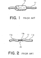
- Fig. 1 is a partial perspective view for use in explaining a method of measures against noise of a conventional antenna device, which mainly illustrates a ferrite core portion.
- Fig. 2 is a partial perspective view for use in explaining another method of measures against noise of the conventional antenna device, which mainly illustrates a soldered portion.
- Fig. 3 is a plan view showing an antenna device according to a first embodiment of the present invention.
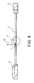
- Fig. 4 is a front view of the antenna device shown in Fig. 3.
- Fig. 5 is an enlarged view of a portion A shown in Fig. 4.
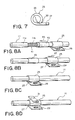
- Figs. 6A, 6B, and 6C are partially enlarged perspective views sequentially showing the assembling the antenna device shown in Figs. 3 and 4.
- Fig. 7 is a side view showing a ground fitting in an antenna device according to a second embodiment of the present invention.
- Figs. 8A, 8B, and 8C are partially enlarged perspective views sequential showing the assembling of the antenna device according to the second embodiment of the present invention.
- a method of decreasing noises In the conventional antenna device, when a signal is received from an antenna main body (not shown) through a coaxial cable 11 in a signal processor (not shown), noises produced by the antenna main body may, in some cases, be picked up by the signal processor through the coaxial cable 11.
- One of methods of decreasing noises according to the prior art is a method of mounting a cylindrical ferrite core 13 on the coaxial cable 11.
- the ferrite core 13 shown in Fig. 1 is high in cost and is large. Therefore, there is a malfunction in space-saving wiring.
- an antenna device 17 includes an antenna main body 19 provided with a GPS antenna (not shown) and a coaxial cable 11 drawn from the antenna main body 19.
- a plug or connector 21 for connection to a signal processor or a GPS processor (not shown) is provided at a front end of the coaxial cable 11.
- a cylindrical ground fitting or shielding fitting 25 is mounted halfway in the coaxial cable 11.
- the ground fitting 25 has a cylindrical connection portion 23 provided at its-one end so as to cover the periphery of a part or a shield portion of the coaxial cable 11.
- the ground fitting 25 is provided with a mounting portion 27 composed of a plate member extending outward in the radial direction of the cable 11 from the connection portion 23.
- the mounting portion 27 has a screw hole 29 provided near its tip end.
- connection portion 23 is mounted on and fixed to the coaxial cable 11 by caulking, as described in detail below.
- the outer conductor 11 b of the coaxial cable 11 from which the outer skin 11 a composed of an insulating material is stripped is exposed to an intermediate part of the coaxial cable 11.
- the outer conductor 11b is a conductor forming a shield, as is well known, and is generally composed of a thin conductive wire braded into a cylindrical mesh shape.
- the connection portion 23 having an opening 35 is inserted into an exposed part of the outer conductor 11 b, to mount the ground fitting 25 such that the outer conductor 11b to which the coaxial cable 11 is exposed is positioned within a cylinder of the connection portion 23.
- connection portion 23 is then caulked by applying a force, as indicated by an arrow 33, with a jig 31 applied to a part of the outer periphery of the connection portion 23.
- the opening 35 is closed, and a recess 37 in a direction crossing the axial direction is formed in the outer periphery of the cylinder of the connection portion 23. Consequently, the ground fitting 25 is firmly fixed to the exposed part of the outer conductor 11 b of the coaxial cable 11.
- the ground fitting 25 is mounted by being screwed to a desired grounded area of a vehicle (not shown) through the screw hole 29 provided in the mounting portion 27.
- the antenna device according to the second embodiment of the present invention has approximately the same configuration as that of the antenna device according to the first embodiment shown in Figs. 3 and 4 except that it differs in the shape of the ground fitting and a mounting method thereof. Consequently, the same parts as those in the first embodiment are assigned the same reference numerals.
- a connection portion 23 in a ground fitting 25 includes a joining portion 39 having a front end folded in a cylindrical shape and a base end previously joined to each other by welding or the like, and has no cuts. Further, the connection portion 23 is formed in the shape of a cylinder comprising a hole having approximately the same thickness as that of the coaxial cable 11.
- an outer conductor exposed portion 41 is formed in an intermediate part of the coaxial cable 11.
- An outer conductor 11b in the coaxial cable 11 is exposed because an outer skin 11 a composed of an insulating material is stripped.
- the outer conductor 11b is a conductor forming a shield, as is well known, and is generally composed of a thin conductive wire braded into a cylindrical mesh shape.
- a cylindrical member 43 composed of a copper cylinder is previously inserted from one end of the coaxial table 11, and the connection portion 23 is further similarly inserted from one end of the coaxial cable 11.
- the cylindrical member 43 is slid and moved to a position of the outer conductor exposed portion 41 in the axial direction of the coaxial cable 11 as indicted by an arrow 45 of Fig. 8A.
- the outer conductor exposed portion 41 in the coaxial cable 11 is positioned in a cylinder of the connection portion 23 in the ground fitting 25, and the ground fitting 25 is slid and moved in the axial direction indicated by an arrow 47 of Fig. 8B such that the connection portion 23 covers the cylindrical member 43.
- both the cylindrical member 43 and the connection portion 23 are then caulked by applying a force with a jig 31 applied to a part of the outer periphery of the connection portion 23.
- a recess (37 in Fig. 6C) in a direction crossing the axial direction is formed in the outer periphery of the cylinder of the connection portion 23, similarly to that shown in Fig. 6C. Consequently, the ground fitting 25 is firmly fixed to the exposed part of the outer conductor 11b of the coaxial cable 11 through the cylindrical member 43.
- the ground fitting 25 is screwed to a desired grounded area of a vehicle (not shown) through a screw hole 29 provided in a mounting portion 27, as in the above-mentioned first embodiment.
- an antenna device can be provided which is capable of reducing the costs of materials for components and the number of steps and a method of decreasing noises produced by an antenna main body.
- an antenna device can be provided which is capable of avoiding stresses at the time of folding and bending of a cable and a method of decreasing noises produced by an antenna main body.
- the antenna device and the method of decreasing noises produced by the antenna according to the present invention can be applied to measures of decreasing noises of a GPS receiving device of a vehicle and an antenna device which has been subjected to the measures of decreasing noises.
Landscapes
- Details Of Aerials (AREA)
- Position Fixing By Use Of Radio Waves (AREA)
Abstract
Description
- The present invention relates generally to an antenna device and a method of decreasing noises produced by an antenna main body, and more specifically, to an on-vehicle antenna device and a method of decreasing noises produced by an antenna main body.
- An antenna device according to the prior art is used as an antenna outside a vehicle. The antenna device comprises an antenna main body which is connected to a plug or connector through a coaxial cable. The antenna main body is provided with a GPS (Global Positioning System) antenna. The plug is connected to a GPS processor.
- In such an antenna device, when the GPS signal is received from the antenna main body through the coaxial cable in the GPS processor, noises produced by the antenna main body may, in some cases, be picked up by the GPS processor through the coaxial cable. Methods for decreasing the noises include a method of mounting a cylindrical ferrite core on the coaxial cable and a method of directly making GND connection by soldering from the coaxial cable.
- In the method using the ferrite core, however, the ferrite core is high in cost and is large. Therefore, there is a malfunction in space-saving wiring.
- Furthermore, in a case where the soldering is used, when stresses such as bending are applied, disconnection occurs.
- Accordingly, it is an object of the present invention to provide an antenna device capable of reducing the costs of materials for components and the number of steps and a method of decreasing noises produced by an antenna main body.
- It is another object of the present invention to provide an antenna device capable of avoiding stresses at the time of folding and bending of a cable and a method of decreasing noises produced by an antenna main body.
- According to one aspect of the present invention, there is provided an antenna device which comprises an antenna main body, a cable for connecting between the antenna main body and a signal processor for processing a signal received from the antenna main body. The antenna device is characterized in that the cable comprises a shielding fitting, the shielding fitting comprising a connection portion to be connected and fixed to a shield portion of the cable and a mounting portion for making connection and fixing to a ground.
- According to another aspect of the present invention, there is provided a method of decreasing noises produced by an antenna device. The antenna device includes an antenna main body and a cable for connecting between the antenna main body and a signal processor for processing a signal received from the antenna main body. The method is characterized by comprising the steps of: preparing a shielding fitting including a mounting portion for making connection and fitting to a ground and a connection portion to be connected and fixed to a shield portion of the cable; and connecting and fixing the connection portion in the shielding fitting to the shield portion of the cable.
- The foregoing and other objects, features, aspects and advantages of the present invention will become more apparent from the following detailed description of the present invention when taken in conjunction with the accompanying drawings.
- Preferred embodiments according to the present invention will be described in detail with reference to the accompanying drawings.
- Fig. 1 is a partial perspective view for use in explaining a method of measures against noise of a conventional antenna device, which mainly illustrates a ferrite core portion.
- Fig. 2 is a partial perspective view for use in explaining another method of measures against noise of the conventional antenna device, which mainly illustrates a soldered portion.
- Fig. 3 is a plan view showing an antenna device according to a first embodiment of the present invention.
- Fig. 4 is a front view of the antenna device shown in Fig. 3.
- Fig. 5 is an enlarged view of a portion A shown in Fig. 4.
- Figs. 6A, 6B, and 6C are partially enlarged perspective views sequentially showing the assembling the antenna device shown in Figs. 3 and 4.
- Fig. 7 is a side view showing a ground fitting in an antenna device according to a second embodiment of the present invention.
- Figs. 8A, 8B, and 8C are partially enlarged perspective views sequential showing the assembling of the antenna device according to the second embodiment of the present invention.
- Before describing embodiments of the present invention, description will be made as regards a method of decreasing noises produced by an antenna main body according to the prior art in order to facilitate the understanding of the present invention with reference to Figs. 1 and 2.
- Referring to Fig. 1, description will be made as regards a method of decreasing noises according to the prior art. In the conventional antenna device, when a signal is received from an antenna main body (not shown) through a
coaxial cable 11 in a signal processor (not shown), noises produced by the antenna main body may, in some cases, be picked up by the signal processor through thecoaxial cable 11. One of methods of decreasing noises according to the prior art is a method of mounting acylindrical ferrite core 13 on thecoaxial cable 11. However, theferrite core 13 shown in Fig. 1 is high in cost and is large. Therefore, there is a malfunction in space-saving wiring. - Referring to Fig. 2, description will be made as regards another method of decreasing noises according to the prior art. A part of an outer skin 11a, composed of an insulating material such as synthetic resin, of the
coaxial cable 11 is removed. In this state, aportion 15 to which anouter conductor 11 b for shielding is exposed by removing the outer skin 11a is directly soldered to a set plate or the like, to make GND connection. In the case of the method using the soldering shown in Fig. 2, when stresses such as bending are applied to a soldered portion, disconnection occurs. - With reference now to Figs. 3 to 5, an embodiment of the present invention will be described.
- Referring to Figs. 3 and 4, an
antenna device 17 according to a first embodiment of the present invention includes an antennamain body 19 provided with a GPS antenna (not shown) and acoaxial cable 11 drawn from the antennamain body 19. A plug orconnector 21 for connection to a signal processor or a GPS processor (not shown) is provided at a front end of thecoaxial cable 11. - A cylindrical ground fitting or shielding fitting 25 is mounted halfway in the
coaxial cable 11. The ground fitting 25 has acylindrical connection portion 23 provided at its-one end so as to cover the periphery of a part or a shield portion of thecoaxial cable 11. The ground fitting 25 is provided with amounting portion 27 composed of a plate member extending outward in the radial direction of thecable 11 from theconnection portion 23. Themounting portion 27 has ascrew hole 29 provided near its tip end. - The
connection portion 23 is mounted on and fixed to thecoaxial cable 11 by caulking, as described in detail below. - Description will be now made as regards a method of mounting the ground fitting 25 on the
coaxial cable 11. - Referring to Fig. 6A, the
outer conductor 11 b of thecoaxial cable 11 from which the outer skin 11 a composed of an insulating material is stripped is exposed to an intermediate part of thecoaxial cable 11. Theouter conductor 11b is a conductor forming a shield, as is well known, and is generally composed of a thin conductive wire braded into a cylindrical mesh shape. Theconnection portion 23 having anopening 35 is inserted into an exposed part of theouter conductor 11 b, to mount the ground fitting 25 such that theouter conductor 11b to which thecoaxial cable 11 is exposed is positioned within a cylinder of theconnection portion 23. - As shown in Fig. 6B, the
connection portion 23 is then caulked by applying a force, as indicated by anarrow 33, with ajig 31 applied to a part of the outer periphery of theconnection portion 23. - As shown in Fig. 6C, the
opening 35 is closed, and arecess 37 in a direction crossing the axial direction is formed in the outer periphery of the cylinder of theconnection portion 23. Consequently, theground fitting 25 is firmly fixed to the exposed part of theouter conductor 11 b of thecoaxial cable 11. - The ground fitting 25 is mounted by being screwed to a desired grounded area of a vehicle (not shown) through the
screw hole 29 provided in themounting portion 27. - An antenna device according to a second embodiment of the present invention will be then described using Fig. 7, 8A, 8B, 8C, and 8D. The antenna device according to the second embodiment of the present invention has approximately the same configuration as that of the antenna device according to the first embodiment shown in Figs. 3 and 4 except that it differs in the shape of the ground fitting and a mounting method thereof. Consequently, the same parts as those in the first embodiment are assigned the same reference numerals.
- Referring to Fig. 7, a
connection portion 23 in aground fitting 25 includes a joiningportion 39 having a front end folded in a cylindrical shape and a base end previously joined to each other by welding or the like, and has no cuts. Further, theconnection portion 23 is formed in the shape of a cylinder comprising a hole having approximately the same thickness as that of thecoaxial cable 11. - Referring to Figs. 8A to 8D, description will be made as regards a method of mounting the ground fitting 25 on the
coaxial cable 11. - Referring to Fig. 8A, an outer conductor exposed
portion 41 is formed in an intermediate part of thecoaxial cable 11. Anouter conductor 11b in thecoaxial cable 11 is exposed because an outer skin 11 a composed of an insulating material is stripped. Theouter conductor 11b is a conductor forming a shield, as is well known, and is generally composed of a thin conductive wire braded into a cylindrical mesh shape. In order to cover an exposed part of theouter conductor 11 b, acylindrical member 43 composed of a copper cylinder is previously inserted from one end of the coaxial table 11, and theconnection portion 23 is further similarly inserted from one end of thecoaxial cable 11. As shown in Fig. 8B, thecylindrical member 43 is slid and moved to a position of the outer conductor exposedportion 41 in the axial direction of thecoaxial cable 11 as indicted by anarrow 45 of Fig. 8A. - As shown in Fig. 8C, the outer conductor exposed
portion 41 in thecoaxial cable 11 is positioned in a cylinder of theconnection portion 23 in the ground fitting 25, and the ground fitting 25 is slid and moved in the axial direction indicated by anarrow 47 of Fig. 8B such that theconnection portion 23 covers thecylindrical member 43. - As shown in Fig. 8D, both the
cylindrical member 43 and theconnection portion 23 are then caulked by applying a force with ajig 31 applied to a part of the outer periphery of theconnection portion 23. - A recess (37 in Fig. 6C) in a direction crossing the axial direction is formed in the outer periphery of the cylinder of the
connection portion 23, similarly to that shown in Fig. 6C. Consequently, the ground fitting 25 is firmly fixed to the exposed part of theouter conductor 11b of thecoaxial cable 11 through thecylindrical member 43. - The ground fitting 25 is screwed to a desired grounded area of a vehicle (not shown) through a
screw hole 29 provided in a mountingportion 27, as in the above-mentioned first embodiment. - As described in the foregoing, according to the first and second embodiments of the present invention, an antenna device can be provided which is capable of reducing the costs of materials for components and the number of steps and a method of decreasing noises produced by an antenna main body.
- According to the first and second embodiments of the present invention, an antenna device can be provided which is capable of avoiding stresses at the time of folding and bending of a cable and a method of decreasing noises produced by an antenna main body.
- As described in the foregoing, the antenna device and the method of decreasing noises produced by the antenna according to the present invention can be applied to measures of decreasing noises of a GPS receiving device of a vehicle and an antenna device which has been subjected to the measures of decreasing noises.
- Although the present invention has been described and illustrated in detail, it is clearly understood that the same is by way of illustration and example only and is not to be taken by way of limitation, the spirit and scope of the present invention being limited only by the terms of the appended claims. For example, in the above-embodiment, use is made of the coaxial cable as a cable, the present invention is not limited to the coaxial cable. Further, in the above-embodiment, use is made of the GPS antenna device as an antenna device, the present invention is not limited to the GPS antenna device.
Claims (10)
- An antenna device (17) comprising an antenna main body (19), a cable (11) for connecting between the antenna main body (19) and a signal processor for processing a signal received from the antenna main body (19), characterized in that the cable (11) comprises a shielding fitting (25), the shielding fitting (25) comprising a connection portion (23) to be connected and fixed to a shield portion of the cable (11) and a mounting portion (27) for making connection and fixing to a ground.
- The antenna device (17) according to claim 1, characterized in that the cable (11) is a coaxial cable (11) comprising an outer conductor (11b) as the shield portion, the-connection portion (23) in the shielding fitting (25) being in a cylindrical shape, the mounting portion (27) comprising a plate member extending from the connection portion (23), and the connection portion (23) being caulked and mounted so as to cover the outer conductor (11b) exposed to a part of the coaxial cable (11).
- The antenna device (17) according to claim 2, characterized in that the mounting portion (27) comprises a screw hole (29).
- The antenna device (17) according to any one of claims 1 to 3, further comprising a conductive cylindrical member (43) mounted on the periphery of the outer conductor (11b), and characterized in that the connection portion (23) is caulked and mounted so as to cover the exposed outer conductor (11b) through the conductive cylindrical member (43).
- The antenna device (17) according to any one of claims 1 to 4, characterized in that the antenna device (17) is mounted on a vehicle.
- A method of decreasing noises produced by an antenna device (17), said antenna device (17) including an antenna main body (19) and a cable (11) for connecting between the antenna main body (19) and a signal processor for processing a signal received from the antenna main body (19), the method is characterized by comprising the steps of:preparing a shielding fitting (25) including a mounting portion (23) for making connection and fitting to a ground and a connection portion to be connected and fixed to a shield portion of the cable (11); andconnecting and fixing the connection portion (23) in the shielding fitting (25) to the shield portion of the cable (11).
- The method according to claim 6, the cable (11) being a coaxial cable (11) comprising an outer conductor (11b) as the shield portion, the connection portion (23) in the shielding fitting (25) being in a cylindrical shape, the mounting portion (27) comprising a plate member extending from the connection portion (23), characterized in that the connecting and fixing step comprises the step of caulking and mounting the connection portion (23) so as to cover the outer conductor (11 b) exposed to a part of the coaxial cable (11)..
- The method according to claim 7, characterized by using the shielding fitting (25) comprising the mounting portion (27) provided with a screw hole (29).
- The method according to any one of claims 7 to 8, characterized in that said connecting and fitting step comprises the steps of mounting a conductive cylindrical member (43) mounted on the periphery of the outer conductor (11b), and of caulking and mounting the connection portion (23) so as to cover the exposed outer conductor (11 b) through the cylindrical member (43).
- The method according to any one of claims 6 to 9, characterized in that the method is used for a vehicle.
Applications Claiming Priority (2)
| Application Number | Priority Date | Filing Date | Title |
|---|---|---|---|
| JP2004110323A JP2005295398A (en) | 2004-04-02 | 2004-04-02 | ANTENNA DEVICE AND ANTENNA NOISE MEASUREMENT METHOD |
| JP2004110323 | 2004-04-02 |
Publications (2)
| Publication Number | Publication Date |
|---|---|
| EP1583173A1 true EP1583173A1 (en) | 2005-10-05 |
| EP1583173B1 EP1583173B1 (en) | 2008-04-16 |
Family
ID=34880137
Family Applications (1)
| Application Number | Title | Priority Date | Filing Date |
|---|---|---|---|
| EP05250497A Expired - Lifetime EP1583173B1 (en) | 2004-04-02 | 2005-01-31 | Antenna device and protection against antenna noise |
Country Status (4)
| Country | Link |
|---|---|
| EP (1) | EP1583173B1 (en) |
| JP (1) | JP2005295398A (en) |
| CN (1) | CN1677750A (en) |
| DE (1) | DE602005006040T2 (en) |
Cited By (1)
| Publication number | Priority date | Publication date | Assignee | Title |
|---|---|---|---|---|
| WO2008133992A1 (en) * | 2007-04-30 | 2008-11-06 | Hewlett-Packard Development Company, L.P. | Antenna grounding system and method |
Families Citing this family (8)
| Publication number | Priority date | Publication date | Assignee | Title |
|---|---|---|---|---|
| JP4820671B2 (en) * | 2005-06-28 | 2011-11-24 | ミツミ電機株式会社 | Compound antenna device |
| WO2007138670A1 (en) * | 2006-05-29 | 2007-12-06 | Panasonic Corporation | Ac adaptor and mobile terminal apparatus |
| JP5685823B2 (en) * | 2010-03-19 | 2015-03-18 | ソニー株式会社 | High frequency receiving transmission cable and receiving device |
| CN103579756B (en) * | 2012-07-19 | 2016-08-03 | 启碁科技股份有限公司 | Antenna device |
| CN107425260B (en) * | 2017-04-17 | 2022-04-19 | 上海安费诺永亿通讯电子有限公司 | Linear metal antenna |
| CN109802219A (en) * | 2017-11-17 | 2019-05-24 | 神讯电脑(昆山)有限公司 | Antenna ground location structure |
| CN113226854B (en) * | 2018-12-26 | 2022-03-15 | 原田工业株式会社 | Composite antenna device for vehicle |
| CN114094333B (en) * | 2021-11-23 | 2026-03-17 | 维沃移动通信有限公司 | electronic devices |
Citations (4)
| Publication number | Priority date | Publication date | Assignee | Title |
|---|---|---|---|---|
| EP0262755A1 (en) * | 1986-07-25 | 1988-04-06 | General Motors Corporation | Vehicle roof mounted slot antenna with am and fm grounding |
| EP1006667A1 (en) * | 1998-05-25 | 2000-06-07 | Mitsubishi Denki Kabushiki Kaisha | Receiver |
| US20020027532A1 (en) * | 1999-07-08 | 2002-03-07 | Walton Eric K. | On-glass impedance matching antenna connector |
| JP2003309413A (en) * | 2002-04-18 | 2003-10-31 | Kojima Press Co Ltd | Vehicle antenna |
Family Cites Families (3)
| Publication number | Priority date | Publication date | Assignee | Title |
|---|---|---|---|---|
| JPS6338283A (en) * | 1986-08-04 | 1988-02-18 | 松下電器産業株式会社 | Printed circuit board manufacturing equipment |
| JP3491326B2 (en) * | 1994-03-31 | 2004-01-26 | マツダ株式会社 | Feeder wire mounting structure |
| JPH11176527A (en) * | 1997-12-10 | 1999-07-02 | Harness Syst Tech Res Ltd | Connector connection structure |
-
2004
- 2004-04-02 JP JP2004110323A patent/JP2005295398A/en active Pending
-
2005
- 2005-01-10 CN CN200510000389.0A patent/CN1677750A/en active Pending
- 2005-01-31 DE DE602005006040T patent/DE602005006040T2/en not_active Expired - Lifetime
- 2005-01-31 EP EP05250497A patent/EP1583173B1/en not_active Expired - Lifetime
Patent Citations (4)
| Publication number | Priority date | Publication date | Assignee | Title |
|---|---|---|---|---|
| EP0262755A1 (en) * | 1986-07-25 | 1988-04-06 | General Motors Corporation | Vehicle roof mounted slot antenna with am and fm grounding |
| EP1006667A1 (en) * | 1998-05-25 | 2000-06-07 | Mitsubishi Denki Kabushiki Kaisha | Receiver |
| US20020027532A1 (en) * | 1999-07-08 | 2002-03-07 | Walton Eric K. | On-glass impedance matching antenna connector |
| JP2003309413A (en) * | 2002-04-18 | 2003-10-31 | Kojima Press Co Ltd | Vehicle antenna |
Non-Patent Citations (1)
| Title |
|---|
| PATENT ABSTRACTS OF JAPAN vol. 2003, no. 12 5 December 2003 (2003-12-05) * |
Cited By (1)
| Publication number | Priority date | Publication date | Assignee | Title |
|---|---|---|---|---|
| WO2008133992A1 (en) * | 2007-04-30 | 2008-11-06 | Hewlett-Packard Development Company, L.P. | Antenna grounding system and method |
Also Published As
| Publication number | Publication date |
|---|---|
| DE602005006040D1 (en) | 2008-05-29 |
| JP2005295398A (en) | 2005-10-20 |
| CN1677750A (en) | 2005-10-05 |
| DE602005006040T2 (en) | 2008-08-14 |
| EP1583173B1 (en) | 2008-04-16 |
Similar Documents
| Publication | Publication Date | Title |
|---|---|---|
| JP5960797B2 (en) | Roof antenna apparatus for vehicle having roof antenna apparatus or connecting apparatus | |
| US7500878B2 (en) | Microphone connector and method of shielding the same | |
| US6464538B2 (en) | Shield connector and terminal connecting device for shielding electric wire | |
| US7318742B2 (en) | Shield terminal for coaxial cable | |
| KR101616631B1 (en) | Electrical coaxial connector | |
| US20060121758A1 (en) | Method of grounding shielded wire and structure for grounding shielded wire | |
| JP4832384B2 (en) | Antenna connection structure and antenna connection method | |
| JP2012015061A (en) | Shield connector | |
| JP2000294344A (en) | Shield connector structure | |
| JP3738388B2 (en) | Coaxial connector | |
| EP1583173B1 (en) | Antenna device and protection against antenna noise | |
| US9601875B2 (en) | Multi-wire shielded cable and method for manufacturing such a cable | |
| US8299372B2 (en) | Antenna universal mount joint connectors | |
| CN116073162A (en) | Terminals and Connectors | |
| CN100585945C (en) | Antenna device | |
| JP3257202B2 (en) | Earth structure of shielded wire | |
| CN112615177B (en) | Connector and electronic device | |
| JP4836393B2 (en) | Automotive antenna and its component set | |
| CN110036537A (en) | The electric component including coaxial cable and electric terminal for motor vehicles | |
| JP4036671B2 (en) | Vehicle antenna | |
| JP2003308898A (en) | Connection structure of heterogeneous electric wires | |
| JP2003308897A (en) | Connection portion structure for different-type wire | |
| JP3910479B2 (en) | Vehicle antenna | |
| JPH07218536A (en) | Contact probe mounting holder | |
| JP2003317879A (en) | Connector with built-in electronic element |
Legal Events
| Date | Code | Title | Description |
|---|---|---|---|
| PUAI | Public reference made under article 153(3) epc to a published international application that has entered the european phase |
Free format text: ORIGINAL CODE: 0009012 |
|
| AK | Designated contracting states |
Kind code of ref document: A1 Designated state(s): AT BE BG CH CY CZ DE DK EE ES FI FR GB GR HU IE IS IT LI LT LU MC NL PL PT RO SE SI SK TR |
|
| AX | Request for extension of the european patent |
Extension state: AL BA HR LV MK YU |
|
| 17P | Request for examination filed |
Effective date: 20060328 |
|
| AKX | Designation fees paid |
Designated state(s): DE ES FR GB IT |
|
| GRAP | Despatch of communication of intention to grant a patent |
Free format text: ORIGINAL CODE: EPIDOSNIGR1 |
|
| RIN1 | Information on inventor provided before grant (corrected) |
Inventor name: ITO, TSUTOMU,C/O MITSUMI ELECTRIC CO. LTD. Inventor name: KUSANAGI, KANENARI,C/O MITSUMI ELECTRIC CO. LTD. Inventor name: YONEYA, AKIRA,C/O MITSUMI ELECTRIC CO. LTD. Inventor name: IMANO, YOSHIAKI,C/O MITSUMI ELECTRIC CO. LTD. |
|
| GRAS | Grant fee paid |
Free format text: ORIGINAL CODE: EPIDOSNIGR3 |
|
| GRAA | (expected) grant |
Free format text: ORIGINAL CODE: 0009210 |
|
| AK | Designated contracting states |
Kind code of ref document: B1 Designated state(s): DE ES FR GB IT |
|
| REF | Corresponds to: |
Ref document number: 602005006040 Country of ref document: DE Date of ref document: 20080529 Kind code of ref document: P |
|
| PG25 | Lapsed in a contracting state [announced via postgrant information from national office to epo] |
Ref country code: ES Free format text: LAPSE BECAUSE OF FAILURE TO SUBMIT A TRANSLATION OF THE DESCRIPTION OR TO PAY THE FEE WITHIN THE PRESCRIBED TIME-LIMIT Effective date: 20080727 |
|
| PLBE | No opposition filed within time limit |
Free format text: ORIGINAL CODE: 0009261 |
|
| STAA | Information on the status of an ep patent application or granted ep patent |
Free format text: STATUS: NO OPPOSITION FILED WITHIN TIME LIMIT |
|
| EN | Fr: translation not filed | ||
| 26N | No opposition filed |
Effective date: 20090119 |
|
| PGFP | Annual fee paid to national office [announced via postgrant information from national office to epo] |
Ref country code: DE Payment date: 20110126 Year of fee payment: 7 Ref country code: IT Payment date: 20110120 Year of fee payment: 7 |
|
| PGFP | Annual fee paid to national office [announced via postgrant information from national office to epo] |
Ref country code: GB Payment date: 20110126 Year of fee payment: 7 |
|
| PG25 | Lapsed in a contracting state [announced via postgrant information from national office to epo] |
Ref country code: FR Free format text: LAPSE BECAUSE OF FAILURE TO SUBMIT A TRANSLATION OF THE DESCRIPTION OR TO PAY THE FEE WITHIN THE PRESCRIBED TIME-LIMIT Effective date: 20090227 |
|
| GBPC | Gb: european patent ceased through non-payment of renewal fee |
Effective date: 20120131 |
|
| PG25 | Lapsed in a contracting state [announced via postgrant information from national office to epo] |
Ref country code: GB Free format text: LAPSE BECAUSE OF NON-PAYMENT OF DUE FEES Effective date: 20120131 Ref country code: DE Free format text: LAPSE BECAUSE OF NON-PAYMENT OF DUE FEES Effective date: 20120801 |
|
| REG | Reference to a national code |
Ref country code: DE Ref legal event code: R119 Ref document number: 602005006040 Country of ref document: DE Effective date: 20120801 |
|
| PG25 | Lapsed in a contracting state [announced via postgrant information from national office to epo] |
Ref country code: IT Free format text: LAPSE BECAUSE OF NON-PAYMENT OF DUE FEES Effective date: 20120131 |