EP1583119B1 - Système de verrouillage pour une commande linéaire - Google Patents
Système de verrouillage pour une commande linéaire Download PDFInfo
- Publication number
- EP1583119B1 EP1583119B1 EP20050102351 EP05102351A EP1583119B1 EP 1583119 B1 EP1583119 B1 EP 1583119B1 EP 20050102351 EP20050102351 EP 20050102351 EP 05102351 A EP05102351 A EP 05102351A EP 1583119 B1 EP1583119 B1 EP 1583119B1
- Authority
- EP
- European Patent Office
- Prior art keywords
- rod
- locking system
- movement
- translation
- balls
- Prior art date
- Legal status (The legal status is an assumption and is not a legal conclusion. Google has not performed a legal analysis and makes no representation as to the accuracy of the status listed.)
- Expired - Lifetime
Links
- 230000000694 effects Effects 0.000 claims description 4
- 230000003100 immobilizing effect Effects 0.000 description 3
- 230000003993 interaction Effects 0.000 description 3
- 125000006850 spacer group Chemical group 0.000 description 3
- 230000006835 compression Effects 0.000 description 2
- 238000007906 compression Methods 0.000 description 2
- 230000000903 blocking effect Effects 0.000 description 1
- 238000005096 rolling process Methods 0.000 description 1
Images


Classifications
-
- H—ELECTRICITY
- H01—ELECTRIC ELEMENTS
- H01H—ELECTRIC SWITCHES; RELAYS; SELECTORS; EMERGENCY PROTECTIVE DEVICES
- H01H3/00—Mechanisms for operating contacts
- H01H3/22—Power arrangements internal to the switch for operating the driving mechanism
- H01H3/30—Power arrangements internal to the switch for operating the driving mechanism using spring motor
- H01H3/3031—Means for locking the spring in a charged state
-
- H—ELECTRICITY
- H01—ELECTRIC ELEMENTS
- H01H—ELECTRIC SWITCHES; RELAYS; SELECTORS; EMERGENCY PROTECTIVE DEVICES
- H01H3/00—Mechanisms for operating contacts
- H01H3/22—Power arrangements internal to the switch for operating the driving mechanism
- H01H3/30—Power arrangements internal to the switch for operating the driving mechanism using spring motor
- H01H3/3052—Linear spring motors
-
- H—ELECTRICITY
- H01—ELECTRIC ELEMENTS
- H01H—ELECTRIC SWITCHES; RELAYS; SELECTORS; EMERGENCY PROTECTIVE DEVICES
- H01H3/00—Mechanisms for operating contacts
- H01H3/22—Power arrangements internal to the switch for operating the driving mechanism
- H01H3/30—Power arrangements internal to the switch for operating the driving mechanism using spring motor
- H01H3/3031—Means for locking the spring in a charged state
- H01H2003/3036—Means for locking the spring in a charged state using of balls or rollers in the locking device
Definitions
- the present invention relates to a locking system for immobilizing or releasing the translation movement of a rod of a linear control, the rod being movable in an axial direction between a first position and a second position spaced a certain distance according to the axial direction of the first position.
- the invention more particularly relates to a locking system for a linear mechanical spring control used to move the moving contact crew of a high or medium voltage circuit breaker.
- the two positions of the rod of the linear control correspond to the two positions of the movable contact equipment of the circuit breaker.
- the first position of the rod corresponds to the position of the moving contact crew when the circuit breaker is open and the second position of the rod corresponds to the position of the moving contact crew when the circuit breaker is closed.
- the translation movement of the rod in the axial direction is maintained by springs and in particular helical springs which serve to store the kinetic energy to perform successive switching of the circuit breaker.
- Patent document is known US2003 / 0034331 , a linear control of the type indicated above with a locking system to immobilize or release the translation movement of the rod.
- This locking system is constituted by a pawl controlled by an electric coil.
- a snap locking system is not suitable for spring loaded controls with springs exerting significant forces on the rod.
- this type of locking system is not adapted to lock the position of the rod in both directions of movement of the rod in the axial direction.
- the object of the invention is to provide a locking system for immobilizing or releasing the translational movement of a rod of a linear control for high or medium voltage circuit breaker for example, which is reliable and fast and which supports axial forces the rod during switching operations of the circuit-breaker.
- the subject of the invention is a locking system for immobilizing or releasing the translational movement of a rod of a linear control, the rod being movable in an axial direction between a first position and a second position spaced apart by a certain distance in the axial direction of the first position, characterized in that it comprises two circumferential grooves formed on the rod and spaced from each other in the axial direction of said certain distance and a plurality of balls distributed over the periphery of the rod to cooperate with said circumferential grooves, said balls being mounted in an annular cage surrounding the rod, said annular cage comprising a first annular portion fixed in the axial direction, surrounding the rod and traversed by the balls and a second movable portion relative to the fixed annular portion, surrounding the first annular portion with the balls and ag enco rotational or translationally driven relative to the first annular portion under the effect of an axial force exerted on the rod to release the translational movement of the rod.
- the cage is arranged so that a rotational movement of the mobile part around the rod in a first angular direction causes the release of the translation movement of the rod. in one direction and a rotational movement of the moving part around the rod in a reverse direction causes immobilization of the translation movement of the rod.
- the cage is arranged so that a translational movement in the axial direction of the movable part in a first direction causes the release of the translation movement of the rod. and that a translational movement of the movable part in a reverse direction causes immobilization of the translation movement of the rod.
- the mobile part comprises grooves in which the balls are introduced when the moving part occupies an angular position which causes the release of the translational movement of the rod and wherein the movable portion has between two consecutive grooves an inner surface which forms a ramp on which the balls move.
- the mobile part comprises a circumferential groove in which the balls are introduced when the movable part occupies a position in the axial direction A which causes the release of the movement of translation of the rod and wherein a flank of the circumferential groove is interrupted to extend into a frustoconical bore which forms a ramp on which the balls move.
- the circumferential grooves have inclined flanks with respect to the axis of the rod.
- the mobile part is immobilized and mobilized by means of an electromagnet.
- the locking system comprises a return spring which opposes the rotational movement or translation of the movable part.
- an axial force exerted on the rod of the linear control creates a torque by the interaction of the balls on the inclined sides of the grooves and on the ramps between the grooves of the cage which tends to drive the mobile part of the cage in a rotary movement around the rod so that it is sufficient to release the rotary movement of the movable part of the cage to release the translational movement of the rod.
- the release of the translation movement of the rod can be performed in both directions of the axial direction and this quickly with little energy.
- the figure 1 shows very schematically a linear mechanical control springs fitted to a high-voltage circuit breaker and provided with a locking system according to the invention.
- the figure 2 shows in an enlarged way the linear mechanical control with springs of the figure 1 with the locking system according to a first embodiment of the invention.
- the figure 3 is a partial schematic sectional view along AA on the figure 4 of the annular cage of the locking system according to a first embodiment of the invention.
- the figure 4 is a radial sectional view of the annular cage of the locking system according to a first embodiment of the invention.
- the figure 5 is an enlarged view in radial section of a portion of the cage of the locking system according to a first embodiment of the invention.
- the figure 6 schematically illustrates the locking system with an electromagnet for blocking the rotary movement of the annular cage according to a first embodiment of the invention.
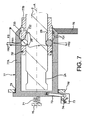
- the figure 7 is a partial schematic sectional view along the axial direction A of the locking system according to a second embodiment of the invention.
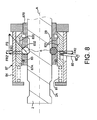
- the figure 8 illustrates a schematic partial sectional view along the axial direction A of the locking system according to a third embodiment of the invention.
- FIG. 1 very schematically, an example of application of the locking system according to the invention for a linear mechanical control springs fitted to a high-voltage circuit breaker 1.
- the circuit breaker 1 is shown here in the open position.
- the rod 2 of the linear mechanical control 3 is integral in motion of the movable contact 4 of the circuit breaker 1 which is separated here from the fixed contact of the circuit breaker.
- the locking system 5 blocks the translational movement of the rod 2 in the axial direction A.
- the figure 2 is an enlargement of the linear spring control 3 shown on the figure 1 according to a first embodiment of the invention.
- the rod 2 is provided with two circumferential grooves 2A, 2B spaced apart from one another in the axial direction A by a distance corresponding to the distance traveled by the rod 2 when it is displaced between a first position corresponding to the closing position of the circuit breaker and a second position corresponding to the opening position of the circuit breaker.
- the locking system 5 is shown according to the first embodiment. However, it will be seen later that a locking system according to a second and a third embodiment of the invention can be applied to the linear control 3.
- the locking system 5 comprises a plurality of balls 6 distributed over the circular periphery of the rod 2 to cooperate with one of the grooves 2A or 2B of the rod.
- the balls 6 are mounted in an annular cage 7 fixed via a disk 8 to the tubular housing 9 of the control 3.
- two bearing discs 10 and 11 are fixedly mounted in the axial direction A, being spaced apart from each other in the axial direction A, between the two springs 3A and 3B. These two disks 10, 11 are engaged in the tubular housing 9 of the control 3. Furthermore, two other support discs 12, 13 are arranged on either side of the pair of disks 10 and 11 in the direction axial A, these discs 12, 13 being integral and movable in the axial direction A with the rod 2.
- the two springs 3A, 3B are helical springs which are arranged coaxially with respect to each other around the rod 2
- the trip spring 3A which is disposed here between the locking system 5 and the spring 3B, is maintained between the discs 10 and 12 while the engagement spring 3B is held between the discs 11 and 13.
- the interengagement spring 3B maintained compressed between the disks 11 and 13 exerts on the rod 2 an axial force which tends to move the rod 2 in the axial direction upwards on the figure 2 so that a loosening of the locking system 5 (release of the balls 6 of the groove 2B) will cause the switching of the circuit breaker 1 in the closed position parallel to the compression of the spring 3A between the discs 10 and 12.
- the groove 2A is in front of the locking system 5 which can be operated as described below to lock the translational movement of the rod.
- the figure 3 illustrates a partial schematic sectional view along AA on the figure 4 of the annular cage 7 of a first embodiment of the locking system 5 according to the invention.
- the annular cage 7 comprises a first ring-shaped annular portion 7A which is rotatable about a second annular ring-shaped fixed portion 7B, the latter surrounding the rod 2 and is integral with the control box 9 via the disc 8 (not shown in this figure).
- the rotatable annular portion 7A is disposed between a circumferential outer rib 7B 'of the fixed annular portion 7B and a set of clamping rings 7B "which abut the annular portion 7A against the rib 7B'.
- the annular portion 7B comprises a set of radial holes 7C 'in which are housed respectively the balls 6.
- the balls 6 are engaged both in the holes 7C 'and in the groove 2B to immobilize the movement of the rod 2 in the axial direction A.
- the circumferential groove 2B (like the groove 2A) has flanks 2B 'which are not perpendicular with respect to the axis of the rod 2 but which are inclined by an angle ⁇ (of the order of 60 °) by relative to the axis of the rod 2. More particularly, in section the groove forms a U whose branches flare towards the opening of the U so as to form each a sort of ramp for the balls 6.
- the arrow FS is shown the force exerted by the engagement spring 3B on the rod 2.
- the arrow FR1 represents a radial reaction force exerted on each ball 6 by the inclined flank 2B 'of the groove 2B. It is understood that the direction of the force FR1 is perpendicular to the axial direction A.
- FIG 4 a schematic radial sectional view of the annular cage 7 of the locking system 5 according to the first embodiment of the invention is shown, in which the fixed annular portion 7B and the annular mobile ring portion 7A are seen.
- the movable annular portion 7A comprises splines 30 distributed on the inner periphery whose number is identical to the number of balls 6 and in each of which a ball is retracted to clear the circumferential groove 2B (or the groove 2A).
- Each groove extends perpendicular to the axis of the rod 2.
- Each groove 30 extends perpendicularly to the axis of the rod 2.
- the depth of the grooves 30 is slightly greater than the depth of the groove 2B (or throat 2A).
- each groove has a U-shaped cross-section, the branches of the "U” flaring towards the opening of the "U". More particularly, each groove has two flanks 31 which are inclined relative to a radial direction of an angle of 30 °, for example.
- the junction zone between two consecutive grooves on the inner surface of the movable annular part 7A also defines a kind of ramp 32 which rises on the inside of the part 7A of the cage to join the edge of a inclined side 31 of a groove 30 (the left flank on the figure 5 ).
- the ramp 32 is arranged so that the axial reaction force FR1, transmitted via each of the balls 6 to the corresponding ramp 32, generates a tangential component FR2. The latter tends to impose a rotational movement on the mobile part 7A of the annular cage 7.
- the direction of the force FR2 is the line perpendicular to the direction of FR1.
- the force FR2 is applied to the point of contact between the ball 6 and the corresponding ramp 32.
- said ramp is an inclined plane of angle ⁇ (of a few degrees) with respect to the line perpendicular to the direction of FR1.
- ⁇ of a few degrees
- the balls 6 are held in the holes of the part 7B on one side by the groove 2B (or 2A) and on the other by the ramp 32.
- the ramp 32 could not not have a flat surface.
- the combination of all the FR2 forces produced by the balls 6 on the ramps 32 is a pair MR2 which acts to rotate the movable portion 7A of the annular cage 7 in the direction indicated by the arrow MR2 (trigonometric direction).
- MR2 trigonometric direction
- the rotation of the movable portion 7A of the annular cage 7 in the direction of MR2 causes the balls 6 to coincide with the splines 30, which allows the balls 6 to be released from the groove 2B and thus release the movement in translation of the rod 2.
- an electromagnet 40 and a return spring 41 are respectively used to block the rotational movement of the portion 7A of the annular cage and to return to a locking position this portion 7A of the annular cage .
- the electromagnet 40 is fixed to a frame 42 disposed inside the housing 9 and comprises for example a "U" shaped magnet 43, a rotating part 44 arranged in the air gap of the magnet, a finger 45 and a return spring 46.
- the mobile part 7A of the annular cage 7 has a radial handle on its outer periphery whose end is in abutment against the workpiece 44.
- the torque MR2 exerted on the annular cage is indicated on the figure 6 and it is seen that the return spring 41 exerts a force on the handle of the movable part 7A which opposes the MR2 pair.
- the piece 44 is locked in position, pressing the support of the electromagnet on one side and pulled by the return spring 46 on the other side.
- the part 44 In response to an electrical pulse applied to the magnet 43, the part 44 is rotated in the air gap of the magnet 43, which consequently releases the rotary movement of the annular cage 7 in the trigonometrical direction indicated by the arrow MR2.
- the rotation of the annular cage in the direction of MR2 causes a rise of the balls 6 in the grooves 30 and thus the release of the translational movement of the rod 2. This results in a circuit breaker switching in a closed position. In this position of the circuit breaker, the annular cage 7 surrounds the annular groove 2A.
- the locking system 5 operates in the same way for switching the circuit breaker from a closed position to an open position.
- an axial force exerted on the rod of the linear control creates a torque by the interaction of the balls on the inclined sides of the grooves of the rod and on the ramp in the extension of a flank of the groove of the movable part which tends to drive the moving part of the cage in a translation movement in the axial direction so that it is sufficient to release the translational movement of the movable part of the cage to release the translational movement of the rod.
- the release of the translation movement of the rod can be performed in both directions of the axial direction and this quickly with little energy.
- the figure 7 illustrates a schematic partial sectional view along the axial direction A of the locking system according to a second embodiment of the invention.
- the locking system according to the second embodiment of the invention is applied to a mechanical spring drive for a high and medium voltage circuit breaker as described in the first embodiment and illustrated above by the figures 1 and 2 .
- the rod 2 of the control is shown with the grooves 2A and 2B.
- the locking system 5 here comprises an annular cage 77 surrounding the rod 2 and in which the balls 6 are arranged.
- the annular cage 77 comprises a ring-shaped fixed annular portion 77B having radial holes distributed over its circular periphery in which are the annular portion 77B is attached to the housing 9 (not shown on the figure 7 )
- the annular cage 77 also comprises a cylindrical sleeve shaped annular portion 77A fitted on the end of the rod 2 and surrounding the annular ring-shaped portion 77B.
- the part in sleeve form 77A is movable in the axial direction A.
- the sleeve-shaped movable portion 77A includes an inner circumferential groove 730 that surrounds the fixed ring 77B and wherein the plurality of balls 6 retract when the movable bushing 77A occupies a certain position along the axis A corresponding to the release of the translation movement of the rod 2.
- the depth of the groove 730 is slightly greater than the depth of the groove 2B (or the groove 2A).
- This groove 730 has flanks 731 inclined at an angle of 30 °, for example, with respect to a radial direction.
- One of the flanks 731 is interrupted to extend into a frustoconical bore which tapers toward the axis A towards the bottom of the movable bushing 77A to form an annular ramp 732.
- said ramp 732 is a plane inclined a few degrees with respect to the axial direction A and a function similar to the plane 32 on the figure 5 .
- the plurality of balls 6 is engaged, on one side, in the groove 2B and maintained on the other by the ramp 732.
- the rod 2 of the control is thus maintained in the stationary position.
- the arrow FS is shown the force exerted by the engagement spring 3B on the rod 2.
- the arrow FR1 represents the reaction force transmitted through the plurality of balls 6 to the movable sleeve 77A. It is understood that the direction of the force FR1 is the radial direction at the point of contact between the corresponding ball 6 and the ramp 732.
- This force FR1 is thus applied to the ramp 732 so that it generates an axial force FR2 'acting to cause the translational movement of the movable sleeve 77A in the opposite direction of the force FS of the engagement spring 3B.
- This translational movement of the movable bushing 77A is blocked by an electromagnet 73, similar to that of the first embodiment and fixed to the housing 9 (not shown in FIG. figure 7 ).
- the electromagnet 73 controls, by means of a rotating part 74, the rotation of a rod-shaped rod 75 mounted on a pivot and connected by an oblong hole to the movable bushing 77A, so that Rotation of the rotating part 74 causes, via the rod 75, the release of the translational movement of the movable sleeve 77A driven under the effect of the force FR2 '.
- the balls 6 then move in the holes of the fixed ring 77B and retract in the groove 730 of the movable sleeve 77A.
- the rod 2 is released and undergoes a translation movement driven by the force FS. This results in a circuit breaker switching in the closed position.
- the groove 730 of the movable sleeve 77A faces the circumferential groove 2A.
- a return spring 71 disposed coaxially with the rod 2 between an abutment 76, integral with the housing 9, and the outer bottom of the bushing 77A, acts to return the latter to the position of immobilization of the rod, that is to say in the direction of the FS force.
- the bottom of the mobile socket 77A is widened so as to abut on a disc 76 ', integral with the housing 9, thus limiting its stroke in the direction of the force FS.
- the disc 76 ' surrounds and guides the movable sleeve 77A through a spacer 79 with a low coefficient of friction.
- a second spacer 79 'with a low coefficient of friction secured to the fixed ring 77B guides and facilitates the sliding of the movable sleeve 77A.
- the balls 6 move in the holes of the fixed ring 77B and retract into the groove 2A of the rod 2, pushed by the ramps 731 and 732 of the movable sleeve 77A.
- the electromagnet acts to hold still the rod 2 of the control in this closed position of the circuit breaker.
- the locking system according to the second embodiment operates in a similar manner for switching the circuit breaker from a closed position to an open position.
- an axial force exerted on the rod of the linear control creates a torque by the interaction of the balls on the inclined flanks of the grooves of the rod and on the ramp in the extension of a flank of the groove of the movable part which tends to drive the mobile part of the cage in a translation movement in the axial direction so that it is sufficient to release the translational movement of the moving part of the cage to release the translational movement of the rod.
- the release of the translation movement of the rod can be made in both directions of the axial direction and this quickly with little energy.
- the figure 8 illustrates a schematic partial sectional view along the axial direction A of the locking system according to a third embodiment of the invention.
- the locking system according to the third embodiment of the invention is applied to a mechanical spring drive for a high and medium voltage circuit breaker as described in the first embodiment and illustrated above by the figures 1 and 2 .
- the rod 2 of the control is shown with the grooves 2A and 2B.
- the locking system 5 here comprises an annular cage 87 surrounding the rod 2 and in which the balls 6 are arranged.
- the annular cage 87 comprises a ring-shaped first annular portion 87B having radial holes distributed over its circular periphery in which the balls 6 are arranged.
- the annular portion 87B is fixed to the casing 9 (not shown in FIG. figure 8 ) by means not shown on the figure 8 .
- the annular cage 87 also comprises a second ring-shaped cylindrical movable portion 87A surrounding the fixed annular portion 87B.
- the cylindrical movable portion 87A is movable in translation in the axial direction A.
- a third fixed portion 84 in the form of an open bottom sleeve surrounds the movable portion 87A.
- the bushing 84 fitted by the end of the rod 2 has its bottom open to allow the rod 2 to pass during its movement. translation and is integral with the fixed annular portion 87B.
- the movable ring 87A is provided with an inner circumferential groove 830 which surrounds the fixed ring 87B and in which the plurality of balls 6 retract when the movable ring 87A occupies a certain position along the axis A corresponding to the release the translation movement of the rod 2.
- the depth of the groove 830 is slightly greater than the depth of the groove 2B (or the groove 2A).
- This groove 830 has flanks 831 inclined at an angle of 30 °, for example, with respect to a radial direction.
- One of the flanks 831 is interrupted to extend into a frustoconical bore which tapers towards the axis A going towards the bottom of the bushing 84 to form an annular ramp 832.
- said ramp 832 is a inclined plane of a few degrees with respect to the axial direction A.
- An annular spacer 83 with a low coefficient of friction fixed to the fixed ring 87B promotes the sliding of the movable ring 87A.
- the plurality of balls 6 is engaged, on one side, in the groove 2B and maintained on the other by the ramp 832.
- the control rod 2 is thus maintained in the stationary position.
- the arrow FS is shown the force exerted by the engagement spring 3B on the rod 2.
- the arrow FR1 represents the reaction force transmitted through the plurality of balls 6 to the movable ring 87A.
- the direction of the FR1 force is the radial direction at the point of contact between the corresponding ball 6 and the ramp 832.
- This force FR1 is therefore applied to the ramp 832 so that it generates an axial force FR2 'acting to drive the translational movement of the movable sleeve 87A in the opposite direction of the force FS of the engagement spring 3B.
- This translational movement of the movable bushing 87A is blocked by an electromagnet (not shown on the figure 8 ) fixed to the housing 9.
- the open-bottomed bushing 84 comprises an opening arranged to allow an "L" -shaped rod 85 connected to the movable ring 87A to move.
- the connecting rod 85 is connected outside the cage 87A to the electromagnet (not shown on the figure 8 ) by means of a rotating part (not shown on the figure 8 ), so that a rotation of the latter causes, via the connecting rod 85, the release of the translational movement of the movable ring 87A driven under the effect of the force FR2 '.
- the balls 6 then move in the holes of the fixed ring 87B and retract in the groove 830 of the movable ring 87A.
- the rod 2 is released and undergoes a translational movement driven by the force FS. This results in a circuit breaker switching in the closed position.
- the groove 830 of the movable ring 87A faces the circumferential groove 2A.
- the balls 6 move in the holes of the fixed ring 87B and retract into the groove 2A of the rod 2, pushed by the ramps 831 and 832 of the movable ring 87A.
- the electromagnet acts to hold still the rod 2 of the control in this closed position of the circuit breaker.
- the locking system according to the third embodiment operates in a similar manner for switching the circuit breaker from a closed position to an open position.
- the locking system according to the invention can be applied to a linear mechanical spring control for high or medium voltage disconnector or to a linear mechanical control with springs for high or medium voltage earthing switches.
- the linear electrical equipment 14 for driving and controlling the movement of the control rod 2 may be, for example, a servomotor connected to a rack. It is possible to replace the springs of the control completely and to control and control the movement of the rod by this servomotor only.
- the angle of inclination of the flanks of the grooves 2A, 2B and 32, 732, 832 planes may be chosen so as to obtain a rolling of the balls in the annular cage rather than sliding.
Landscapes
- Driving Mechanisms And Operating Circuits Of Arc-Extinguishing High-Tension Switches (AREA)
- Bearings For Parts Moving Linearly (AREA)
- Transmission Devices (AREA)
Description
- La présente invention concerne un système de verrouillage pour immobiliser ou libérer le mouvement de translation d'une tige d'une commande linéaire, la tige étant mobile selon une direction axiale entre une première position et une deuxième position espacée d'une certaine distance selon la direction axiale de la première position.
- L'invention concerne plus particulièrement un système de verrouillage pour une commande mécanique linéaire à ressorts utilisée pour déplacer l'équipage de contacts mobiles d'un disjoncteur à haute ou moyenne tension.
- Dans un tel agencement, les deux positions de la tige de la commande linéaire correspondent aux deux positions de l'équipage de contacts mobiles du disjoncteur. Par exemple, la première position de la tige correspond à la position de l'équipage de contacts mobiles quand le disjoncteur est ouvert et la seconde position de la tige correspond à la position de l'équipage de contacts mobiles quand le disjoncteur est fermé. Par ailleurs, le mouvement de translation de la tige selon la direction axiale est entretenu par des ressorts et notamment des ressorts hélicoïdaux qui servent à stocker l'énergie cinétique pour réaliser des commutations successives du disjoncteur.
- On connaît du document de brevet
US2003/0034331 , une commande linéaire du type indiqué ci-dessus avec un système de verrouillage pour immobiliser ou libérer le mouvement de translation de la tige. Ce système de verrouillage est constitué par un cliquet commandé par une bobine électrique. Un système de verrouillage par encliquetage n'est pas adapté à des commandes à ressorts avec des ressorts exerçant sur la tige des forces importantes. En plus, ce type de système de verrouillage n'est pas adapté pour verrouiller la position de la tige dans les deux sens de déplacement de la tige selon la direction axiale. - On connaît aussi du document de
brevet EP0801406 , une commande mécanique linéaire à ressorts pour disjoncteur à haute tension qui comprend un système de verrouillage à plusieurs cliquets commandés par des bobines électriques. - On connaît encore du document de
brevet EP1123571 , une commande pour disjoncteur haute tension dans lequel le système de verrouillage est constitué par un moteur électrique qui met en mouvement une tige de la commande par l'intermédiaire d'une chaîne cinématique compliquée pour transformer un mouvement rotatif du moteur en un mouvement de translation de la tige. Un tel agencement présente en outre l'inconvénient d'être instable pour verrouiller la position de la tige. - Le but de l'invention est de proposer un système de verrouillage pour immobiliser ou libérer le mouvement de translation d'une tige d'une commande linéaire pour disjoncteur haute ou moyenne tension par exemple, qui soit fiable et rapide et qui supporte des forces axiales importantes exercées sur la tige lors des opérations de commutation du disjoncteur.
- A cet effet, l'invention a pour objet un système de verrouillage pour immobiliser ou libérer le mouvement de translation d'une tige d'une commande linéaire, la tige étant mobile selon une direction axiale entre une première position et une deuxième position espacée d'une certaine distance selon la direction axiale de la première position, caractérisé en ce qu'il comprend deux gorges circonférentielles formées sur la tige et espacées l'une de l'autre selon la direction axiale de la dite certaine distance et une pluralité de billes réparties sur la périphérie de la tige pour coopérer avec lesdites gorges circonférentielles, lesdites billes étant montées dans une cage annulaire entourant la tige, ladite cage annulaire comprenant une première partie annulaire fixe selon la direction axiale, entourant la tige et traversée par les billes et une deuxième partie mobile par rapport à la partie annulaire fixe, entourant la première partie annulaire avec les billes et agencée de manière à être entraînée en rotation ou en translation par rapport à la première partie annulaire sous l'effet d'une force axiale exercée sur la tige pour libérer le mouvement de translation de la tige.
- Selon un mode de réalisation particulier du système de verrouillage selon l'invention, la cage est agencée de sorte qu'un mouvement de rotation de la partie mobile autour de la tige selon un premier sens angulaire provoque la libération du mouvement de translation de la tige dans un sens et un mouvement de rotation de la partie mobile autour de la tige selon un sens inverse provoque l'immobilisation du mouvement de translation de la tige.
- Selon un autre mode de réalisation particulier du système de verrouillage selon l'invention, la cage est agencée de sorte qu'un mouvement de translation selon la direction axiale de la partie mobile selon un premier sens provoque la libération du mouvement de translation de la tige et qu'un mouvement de translation de la partie mobile selon un sens inverse provoque l'immobilisation du mouvement de translation de la tige.
- Selon un autre mode de réalisation particulier du système de verrouillage selon l'invention, la partie mobile comprend des cannelures dans lesquelles viennent s'introduire les billes quand la partie mobile occupe une position angulaire qui provoque la libération du mouvement de translation de la tige et dans lequel la partie mobile présente entre deux cannelures consécutives une surface intérieure qui forme une rampe sur laquelle se déplacent les billes.
- Selon un autre mode de réalisation particulier du système de verrouillage selon l'invention, la partie mobile comprend une gorge circonférentielle dans laquelle vient s'introduire les billes quand la partie mobile occupe une position selon la direction axiale A qui provoque la libération du mouvement de translation de la tige et dans laquelle un flanc de la gorge circonférentielle s'interrompt pour se prolonger en un alésage tronconique qui forme une rampe sur laquelle se déplacent les billes.
- Selon un autre mode de réalisation particulier du système de verrouillage selon l'invention, les gorges circonférentielles ont des flancs inclinés par rapport à l'axe de la tige.
- Selon encore un mode de réalisation particulier du système de verrouillage selon l'invention, la partie mobile est immobilisée et mobilisée par l'intermédiaire d'un électro-aimant.
- Selon un mode de réalisation particulier du système de verrouillage selon l'invention, le système de verrouillage comprend un ressort de rappel qui s'oppose au mouvement de rotation ou de translation de la partie mobile.
- Avec l'agencement du système de verrouillage selon l'invention, une force axiale exercée sur la tige de la commande linéaire crée un couple par l'interaction des billes sur les flancs inclinés des gorges et sur les rampes entre les cannelures de la cage qui tend à entraîner la partie mobile de la cage dans un mouvement rotatif autour de la tige ce qui fait qu'il suffit de libérer le mouvement rotatif de la partie mobile de la cage pour libérer le mouvement de translation de la tige. Il en résulte que la libération du mouvement de translation de la tige peut être effectuée dans les deux sens de la direction axiale et ceci de façon rapide avec peu d'énergie.
- Un exemple d'un premier mode de réalisation du système de verrouillage selon l'invention est décrit plus en détail ci-après et illustré par les dessins.
- La
figure 1 montre de façon très schématique une commande mécanique linéaire à ressorts équipant un disjoncteur à haute tension et munie d'un système de verrouillage selon l'invention. - La
figure 2 montre de façon agrandie la commande mécanique linéaire à ressorts de lafigure 1 avec le système de verrouillage selon un premier mode de réalisation de l'invention. - La
figure 3 est une vue partielle en coupe schématique selon A-A sur lafigure 4 de la cage annulaire du système de verrouillage selon un premier mode de réalisation de l'invention. - La
figure 4 est une vue en coupe radiale de la cage annulaire du système de verrouillage selon un premier mode de réalisation de l'invention. - La
figure 5 est une vue agrandie en coupe radiale d'une partie de la cage du système de verrouillage selon un premier mode de réalisation de l'invention. - La
figure 6 illustre de façon schématique le système de verrouillage avec un électro-aimant servant au blocage du mouvement rotatif de la cage annulaire selon un premier mode de réalisation de l'invention. - La
figure 7 est une vue partielle en coupe schématique selon la direction axiale A du système de verrouillage selon un deuxième mode de réalisation de l'invention. - La
figure 8 illustre une vue partielle en coupe schématique selon la direction axiale A du système de verrouillage selon un troisième mode de réalisation de l'invention. - Sur la
figure 1 , on a représenté de façon très schématique un exemple d'application du système de verrouillage selon l'invention pour une commande mécanique linéaire à ressorts équipant un disjoncteur haute tension 1. Le disjoncteur 1 est montré ici en position ouverte. La tige 2 de la commande mécanique linéaire 3 est solidaire en mouvement du contact mobile 4 du disjoncteur 1 qui est donc séparé ici du contact fixe du disjoncteur. - On a représenté sur la
figure 1 deux ressorts 3A et 3B de la commande mécanique linéaire 3 qui sont respectivement le ressort de déclenchement pour l'ouverture du disjoncteur et le ressort d'enclenchement pour la fermeture du disjoncteur. Comme visible sur lafigure 1 , le ressort de déclenchement 3A est détendu tandis que le ressort d'enclenchement 3B est comprimé et prêt à entraîner la tige 2 selon la direction axiale A pour une commutation du disjoncteur en position de fermeture. Le système de verrouillage 5 selon l'invention bloque le mouvement de translation de la tige 2 selon la direction axiale A. - La
figure 2 est un agrandissement de la commande linéaire à ressorts 3 montrée sur lafigure 1 , selon un premier mode de réalisation de l'invention. - Comme visible sur la
figure 2 , la tige 2 est munie de deux gorges circonférentielles 2A, 2B espacées l'une de l'autre selon la direction axiale A d'une distance correspondant à la distance parcourue par la tige 2 lorsqu'elle est déplacée entre une première position correspondant à la position de fermeture du disjoncteur et une seconde position correspondant à la position d'ouverture du disjoncteur. - Sur la
figure 2 , on voit que le système de verrouillage 5 est engagé dans la gorge 2B de la tige 2 et maintient le disjoncteur en position d'ouverture. - Le système de verrouillage 5 est représenté selon le premier mode de réalisation. Toutefois, il sera vu par la suite qu'un système de verrouillage selon un deuxième et un troisième mode de réalisation de l'invention peut être appliqué à la commande linéaire 3. Le système de verrouillage 5 comprend une pluralité de billes 6 réparties sur la périphérie circulaire de la tige 2 pour coopérer avec l'une des gorges 2A ou 2B de la tige. Les billes 6 sont montées dans une cage annulaire 7 fixée par l'intermédiaire d'un disque 8 au boîtier tubulaire 9 de la commande 3.
- Comme visible sur la
figure 2 , deux disques d'appui 10 et 11 sont montés fixes selon la direction axiale A, en étant espacés l'un de l'autre selon la direction axiale A, entre les deux ressorts 3A et 3B. Ces deux disques 10, 11 sont en prise dans le boîtier tubulaire 9 de la commande 3. Par ailleurs, deux autres disques d'appui 12,13 sont disposés de part et d'autre de la paire de disques 10 et 11 selon la direction axiale A, ces disques 12, 13 étant solidaires et mobiles selon la direction axiale A avec la tige 2. Les deux ressorts 3A, 3B sont des ressorts hélicoïdaux qui sont disposés coaxialement l'un par rapport à l'autre autour de la tige 2. Le ressort de déclenchement 3A, qui est disposé ici entre le système de verrouillage 5 et le ressort d'enclenchement 3B, est maintenu entre les disques 10 et 12 tandis que le ressort d'enclenchement 3B est maintenu entre les disques 11 et 13. Du fait de la position de la tige 2 sur lafigure 1 par rapport aux disques fixes 10 et 11, le ressort d'enclenchement 3B maintenu comprimé entre les disques 11 et 13 exerce sur la tige 2 une force axiale qui tend à déplacer la tige 2 selon la direction axiale vers le haut sur lafigure 2 de sorte qu'un relâchement du système de verrouillage 5 (libération des billes 6 de la gorge 2B) provoquera la commutation du disjoncteur 1 dans la position de fermeture parallèlement à la compression du ressort 3A entre les disques 10 et 12. En position de fermeture du disjoncteur 1, la gorge 2A se présente en face du système de verrouillage 5 qui pourra être actionné comme décrit plus loin pour verrouiller le mouvement de translation de la tige. - On comprend donc que la détente du ressort de déclenchement 3A entraîne la compression du ressort d'enclenchement 3B et vice versa et que de l'énergie cinétique est transférée d'un ressort à l'autre. Les pertes d'énergie cinétique lors des commutations successives du disjoncteur sont compensées par un équipement électrique 14 placé fixe entre les deux ressorts 3A, 3B pour entraîner et contrôler le mouvement de translation de la tige 2 selon la direction axiale A.
- La
figure 3 illustre une vue partielle en coupe schématique selon A-A sur lafigure 4 de la cage annulaire 7 d'un premier exemple de réalisation du système de verrouillage 5 selon l'invention. Comme visible sur lafigure 3 , la cage annulaire 7 comprend une première partie annulaire 7A en forme de bague qui est mobile en rotation autour d'une seconde partie annulaire fixe 7B également en forme de bague, cette dernière entoure la tige 2 et est solidaire du boîtier 9 de la commande par l'intermédiaire du disque 8 (non représenté sur cette figure). - Comme visible sur la
figure 3 , la partie annulaire mobile en rotation 7A est disposée entre une nervure extérieure circonférentielle 7B' de la partie annulaire fixe 7B et un jeu d'anneaux de serrage 7B" qui mettent en appui la partie annulaire 7A contre la nervure 7B' . - La partie annulaire 7B comprend un ensemble de trous radiaux 7C' dans lesquels sont logées respectivement les billes 6. Sur la
figure 3 , on voit que les billes 6 sont engagées à la fois dans les trous 7C' et dans la gorge 2B pour réaliser un blocage du mouvement de la tige 2 selon la direction axiale A. - Comme visible sur la
figure 3 , la gorge circonférentielle 2B (comme la gorge 2A) comporte des flancs 2B' qui ne sont pas perpendiculaires par rapport à l'axe de la tige 2 mais qui sont inclinés d'un angle β (de l'ordre de 60°) par rapport à l'axe de la tige 2. Plus particulièrement, en section la gorge forme un U dont les branches vont en s'évasant vers l'ouverture du U de sorte à former chacune une sorte de rampe pour les billes 6. - On a représenté par la flèche FS, la force exercée par le ressort d'enclenchement 3B sur la tige 2. La flèche FR1 représente une force de réaction radiale exercée sur chaque bille 6 par le flanc incliné 2B' de la gorge 2B. On comprend que la direction de la force FR1 est perpendiculaire a la direction axiale A.
- Sur la
figure 4 , on a représenté une vue schématique en coupe radiale de la cage annulaire 7 du système de verrouillage 5 selon le premier mode de réalisation de l'invention où l'on voit la partie annulaire fixe 7B et la partie annulaire mobile 7A en forme de bague. La partie annulaire mobile 7A comprend des cannelures 30 réparties sur la périphérie intérieure dont le nombre est identique au nombre de billes 6 et dans chacune desquelles une bille s'escamote pour dégager la gorge circonférentielle 2B (ou la gorge 2A). Chaque cannelure s'étend perpendiculairement à l'axe de la tige 2. Chaque cannelure 30 s'étend perpendiculairement à l'axe de la tige 2. La profondeur des cannelures 30 est légèrement supérieure à la profondeur de la gorge 2B (ou la gorge 2A). - Comme visible sur la
figure 4 , chaque cannelure a une section transversale en forme de "U", les branches du "U" allant en s'évasant vers l'ouverture du "U". Plus particulièrement, chaque cannelure présente deux flancs 31 qui sont inclinés par rapport à une direction radiale d'un angle de 30°, par exemple. - Par ailleurs, comme cela apparaît encore mieux sur la
figure 5 , on voit que la zone de jonction entre deux cannelures consécutives sur la surface intérieure de la partie annulaire mobile 7A définit également une sorte de rampe 32 qui s'élève du côté intérieur de la partie 7A de la cage pour rejoindre le bord d'un flanc incliné 31 d'une cannelure 30 (le flanc gauche sur lafigure 5 ). La rampe 32 est agencée de sorte que la force de réaction axiale FR1, transmise par l'intermédiaire de chacune des billes 6 à la rampe 32 correspondante, engendre une composante tangentielle FR2. Cette dernière tend à imposer un mouvement de rotation à la partie mobile 7A de la cage annulaire 7. La direction de la force FR2 est la droite perpendiculaire à la direction de FR1. La force FR2 est appliquée au point de contact entre la bille 6 et la rampe 32 correspondante. - Dans notre premier exemple de réalisation, ladite rampe est un plan incliné d' angle α (de quelques degrés) par rapport à la droite perpendiculaire à la direction de FR1. En position immobile de la tige 2, les billes 6 sont maintenues dans les trous de la partie 7B d'un côté par la gorge 2B (ou 2A) et de l'autre par la rampe 32. Bien entendu, la rampe 32 pourrait ne pas avoir une surface plane.
- La combinaison de l'ensemble des forces FR2 produites par les billes 6 sur les rampes 32 est un couple MR2 qui agit pour entraîner en rotation la partie mobile 7A de la cage annulaire 7 selon le sens indiqué par la flèche MR2 (sens trigonométrique). Comme on peut le comprendre sur la
figure 4 , la rotation de la partie mobile 7A de la cage annulaire 7 selon le sens de MR2 provoque la mise en coïncidence des billes 6 avec les cannelures 30 ce qui permet le dégagement des billes 6 hors de la gorge 2B et donc la libération du mouvement en translation de la tige 2. La valeur du couple MR2 peut être optimisée par le choix des angles α et β, selon la relation simplifiée suivante :
- Cette relation ne prend pas en compte les coefficients de frottement.
- Sur la
figure 6 , on a représenté de façon schématique un électro-aimant 40 et un ressort de rappel 41 qui servent respectivement à bloquer le mouvement de rotation de la partie 7A de la cage annulaire et à ramener à une position de blocage cette partie 7A de la cage annulaire. L'électro-aimant 40 est fixé à un bâti 42 disposé à l'intérieur du boîtier 9 et comprend par exemple un aimant en forme de "U" 43, une pièce rotative 44 disposée dans l'entrefer de l'aimant, un doigt d'appui 45 et un ressort de rappel 46. Comme visible sur lafigure 6 , la partie mobile 7A de la cage annulaire 7 présente un manche radial sur sa périphérie extérieure dont l'extrémité est en butée contre la pièce 44. Le couple MR2 exercé sur la cage annulaire est indiqué sur lafigure 6 et on voit que le ressort de rappel 41 exerce une force sur le manche de la partie mobile 7A qui s'oppose au couple MR2. Sur lafigure 6 , la pièce 44 est bloquée en position, appuyant sur le support de l'électro-aimant d'un côté et tiré par le ressort de rappel 46 de l'autre côté. - En réponse à une impulsion électrique appliquée à l'aimant 43, la pièce 44 est entraînée en rotation dans l'entrefer de l'aimant 43 ce qui libère en conséquence le mouvement rotatif de la cage annulaire 7 dans le sens trigonométrique indiqué par la flèche MR2. La rotation de la cage annulaire selon le sens de MR2 entraîne une remontée des billes 6 dans les cannelures 30 et donc la libération du mouvement en translation de la tige 2. Il en résulte une commutation du disjoncteur dans une position de fermeture. Dans cette position du disjoncteur, la cage annulaire 7 entoure la gorge annulaire 2A. Sous l'action du ressort de rappel 41 tendant à faire tourner la partie mobile 7A de la cage annulaire 7 dans le sens inverse du sens trigonométrique, les billes 6 sont engagées dans la gorge circonférentielle 2A pour un nouveau blocage du mouvement en translation de la tige 2 tandis que la pièce rotative 44 est amenée dans une position de blocage sous l'action du ressort de rappel 46 tendu entre la pièce 44 et le doigt 45.
- Le système de verrouillage 5 fonctionne de la même manière pour une commutation du disjoncteur d'une position de fermeture à une position d'ouverture.
- Avec l'agencement du système de verrouillage selon un deuxième mode de réalisation de l'invention, une force axiale exercée sur la tige de la commande linéaire crée un couple par l'interaction des billes sur les flancs inclinés des gorges de la tige et sur la rampe dans le prolongement d'un flanc de la gorge de la partie mobile qui tend à entraîner la partie mobile de la cage dans un mouvement de translation selon la direction axiale ce qui fait qu'il suffit de libérer le mouvement de translation de la partie mobile de la cage pour libérer le mouvement de translation de la tige. Il en résulte que la libération du mouvement de translation de la tige peut être effectuée dans les deux sens de la direction axiale et ceci de façon rapide avec peu d'énergie.
- La
figure 7 illustre une vue partielle en coupe schématique selon la direction axiale A du système de verrouillage selon un deuxième mode de réalisation de l'invention. - Le système de verrouillage selon le deuxième mode de réalisation de l'invention est appliqué à une commande mécanique à ressorts pour un disjoncteur haute et moyenne tension comme décrite dans le premier mode de réalisation et illustrée ci-dessus par les
figures 1 et2 . Sur lafigure 7 , on a représenté la tige 2 de la commande avec les gorges 2A et 2B. Le système de verrouillage 5 comprend ici une cage annulaire 77 entourant la tige 2 et dans laquelle sont disposées les billes 6. La cage annulaire 77 comprend une partie annulaire fixe 77B en forme de bague comportant des trous radiaux répartis sur sa périphérie circulaire dans lesquels sont disposées les billes 6. La partie annulaire 77B est fixée au boîtier 9 (non montré sur lafigure 7 ) par l'intermédiaire du disque 78. La cage annulaire 77 comprend également une partie annulaire en forme de douille cylindrique 77A emmanchée sur l'extrémité de la tige 2 et qui entoure la partie annulaire en forme de bague 77B. La partie en forme de douille 77A est mobile selon la direction axiale A. - La partie mobile en forme de douille 77A comprend une gorge circonférentielle intérieure 730 qui entoure la bague fixe 77B et dans laquelle la pluralité de billes 6 s'escamotent quand la douille mobile 77A occupe une certaine position le long de l'axe A correspondant à la libération du mouvement de translation de la tige 2. La profondeur de la gorge 730 est légèrement supérieure à la profondeur de la gorge 2B (ou la gorge 2A). Cette gorge 730 présente des flancs 731 inclinés d'un angle de 30°, par exemple, par rapport à une direction radiale. Un des flancs 731 est interrompu pour se prolonger en un alésage tronconique qui va en se resserrant vers l'axe A en allant vers le fond de la douille mobile 77A pour former une rampe annulaire 732. Dans notre exemple de réalisation, ladite rampe 732 est un plan incliné de quelques degrés par rapport à la direction axiale A et à une fonction analogue au plan 32 sur la
figure 5 . - On voit sur la
figure 7 que la pluralité de billes 6 est engagée, d'un côté, dans la gorge 2B et maintenue de l'autre par la rampe 732. La tige 2 de la commande est donc maintenue en position immobile. On a représenté par la flèche FS, la force exercée par le ressort d'enclenchement 3B sur la tige 2. La flèche FR1 représente la force de réaction transmise par l'intermédiaire de la pluralité de billes 6 à la douille mobile 77A. On comprend que la direction de la force FR1 est la direction radiale au point de contact entre la bille 6 correspondante et la rampe 732. Cette force FR1 est donc appliquée à la rampe 732 de sorte qu'elle engendre une force axiale FR2' agissant pour entraîner le mouvement de translation de la douille mobile 77A dans le sens opposé de la force FS du ressort d'enclenchement 3B. Ce mouvement de translation de la douille mobile 77A est bloqué par un électroaimant 73, similaire à celui du premier mode de réalisation et fixé au boîtier 9 (non montré sur lafigure 7 ). - L'électroaimant 73 commande, par l'intermédiaire d'une pièce rotative 74, la rotation d'une bielle 75 en forme de "L" montée sur pivot et reliée par un trou oblong à la douille mobile 77A, de sorte qu'une rotation de la pièce rotative 74 entraîne, par l'intermédiaire de la bielle 75, la libération du mouvement de translation de la douille mobile 77A entraîné sous l'effet de la force FR2'.
- Les billes 6 se déplacent alors dans les trous de la bague fixe 77B et s'escamotent dans la gorge 730 de la douille mobile 77A. La tige 2 est libérée et subit un mouvement de translation entraînée par la force FS. Il en résulte une commutation du disjoncteur en position de fermeture. Dans cette position du disjoncteur, la gorge 730 de la douille mobile 77A fait face à la gorge circonférentielle 2A.
- Un ressort de rappel 71, disposé coaxialement à la tige 2 entre une butée 76, solidaire du boîtier 9, et le fond extérieur de la douille 77A, agit pour ramener cette dernière en position d'immobilisation de la tige, c'est à dire dans le sens de la force FS. Comme visible sur la
figure 7 , le fond de la douille mobile 77A est élargie de manière à venir en butée sur un disque 76', solidaire du boîtier 9, limitant ainsi sa course dans le sens de la force FS. Le disque 76' entoure et guide la douille mobile 77A par l'intermédiaire d'une entretoise 79 à faible coefficient de frottement. Une deuxième entretoise 79' à faible coefficient de frottement solidaire de la bague fixe 77B guide et facilite le glissement de la douille mobile 77A. - Les billes 6 se déplacent dans les trous de la bague fixe 77B et s'escamotent dans la gorge 2A de la tige 2, poussées par les rampes 731 et 732 de la douille mobile 77A. L'électroaimant agit pour maintenir immobile la tige 2 de la commande dans cette position de fermeture du disjoncteur.
- Le système de verrouillage selon le deuxième mode de réalisation fonctionne de manière similaire pour une commutation du disjoncteur d'une position de fermeture à une position d'ouverture.
- Avec l'agencement du système de verrouillage selon un troisième mode de réalisation de l'invention, une force axiale exercée sur la tige de la commande linéaire crée un couple par l'interaction des billes sur les flancs inclinés des gorges de la tige et sur la rampe dans le prolongement d'un flanc de la gorge de la partie mobile qui tend à entraîner la partie mobile de la cage dans un mouvement de translation selon la direction axiale ce qui fait qu'il suffit de libérer le mouvement de translation de la partie mobile de la cage pour libérer le mouvement de translation de la tige. Il en résulte que la libération du mouvement de translation de la tige peut être effectuée dans les deux sens de la direction axiale et ceci de façon rapide avec peu d'énergie.
- La
figure 8 illustre une vue partielle en coupe schématique selon la direction axiale A du système de verrouillage selon un troisième mode de réalisation de l'invention. - Le système de verrouillage selon le troisième mode de réalisation de l'invention est appliqué à une commande mécanique à ressorts pour un disjoncteur haute et moyenne tension comme décrit dans le premier mode de réalisation et illustrée ci-dessus par les
figures 1 et2 . Sur lafigure 8 , on a représenté la tige 2 de la commande avec les gorges 2A et 2B. Le système de verrouillage 5 comprend ici une cage annulaire 87 entourant la tige 2 et dans laquelle sont disposées les billes 6. La cage annulaire 87 comprend une première partie annulaire fixe 87B en forme de bague comportant des trous radiaux répartis sur sa périphérie circulaire dans lesquels sont disposées les billes 6. La partie annulaire 87B est fixée au boîtier 9 (non montré sur lafigure 8 ) par un moyen non montré sur lafigure 8 . La cage annulaire 87 comprend également une deuxième partie mobile cylindrique 87A en forme de bague entourant la partie annulaire fixe 87B. La partie mobile cylindrique 87A est mobile en translation selon la direction axiale A. Une troisième partie fixe 84 en forme de douille à fond ouvert entoure la partie mobile 87A. La douille 84 emmanchée par l'extrémité de la tige 2 a son fond ouvert pour laisser passer la tige 2 lors de son mouvement de translation et est solidaire de la partie annulaire fixe 87B. - La bague mobile 87A est munie d'une gorge circonférentielle intérieure 830 qui entoure la bague fixe 87B et dans laquelle la pluralité de billes 6 s'escamotent quand la bague mobile 87A occupe une certaine position le long de l'axe A correspondant à la libération du mouvement de translation de la tige 2. La profondeur de la gorge 830 est légèrement supérieure à la profondeur de la gorge 2B (ou la gorge 2A). Cette gorge 830 présente des flancs 831 inclinés d'un angle de 30°, par exemple, par rapport à une direction radiale. Un des flancs 831 est interrompu pour se prolonger en un alésage tronconique qui va en se resserrant vers l'axe A en allant vers le fond de la douille 84 pour former une rampe annulaire 832. Dans notre exemple de réalisation, ladite rampe 832 est un plan incliné de quelques degrés par rapport à la direction axiale A. Une entretoise annulaire 83 à faible coefficient de frottement fixée à la bague fixe 87B favorise le glissement de la bague mobile 87A.
- On voit sur la
figure 8 que la pluralité de billes 6 est engagée, d'un côté, dans la gorge 2B et maintenue de l'autre par la rampe 832. La tige de commande 2 est donc maintenue en position immobile. On a représenté par la flèche FS, la force exercée par le ressort d'enclenchement 3B sur la tige 2. La flèche FR1 représente la force de réaction transmise par l'intermédiaire de la pluralité de billes 6 à la bague mobile 87A. On comprend que la direction de la force FR1 est la direction radiale au point de contact entre la bille 6 correspondante et la rampe 832. Cette force FR1 est donc appliquée à la rampe 832 de sorte qu'elle engendre une force axiale FR2' agissant pour entraîner le mouvement de translation de la douille mobile 87A dans le sens opposé de la force FS du ressort d'enclenchement 3B. Ce mouvement de translation de la douille mobile 87A est bloqué par un électroaimant (non montré sur lafigure 8 ) fixé au boîtier 9. - Dans ce troisième mode de réalisation, la douille à fond ouvert 84 comprend une ouverture agencée pour laisser se déplacer une bielle 85 en forme de "L" reliée à la bague mobile 87A. La bielle 85 est reliée à l'extérieur de la cage 87A à l'électroaimant (non montré sur la
figure 8 ) par l'intermédiaire d'une pièce rotative (non montré sur lafigure 8 ), de sorte qu'une rotation de cette dernière entraîne, par l'intermédiaire de la bielle 85, la libération du mouvement de translation de la bague mobile 87A entraîné sous l'effet de la force FR2'. - Les billes 6 se déplacent alors dans les trous de la bague fixe 87B et s'escamotent dans la gorge 830 de la bague mobile 87A. La tige 2 est libérée et subit un mouvement de translation entraîné par la force FS. Il en résulte une commutation du disjoncteur en position de fermeture. Dans cette position du disjoncteur, la gorge 830 de la bague mobile 87A fait face à la gorge circonférentielle 2A.
- Un ressort de rappel 81, disposé de façon coaxiale à la tige 82 entre le fond de la douille 84 et la bague mobile 87A, agit pour ramener la bague mobile 87A dans le sens de la force FS.
- Les billes 6 se déplacent dans les trous de la bague fixe 87B et s'escamotent dans la gorge 2A de la tige 2, poussées par les rampes 831 et 832 de la bague mobile 87A. L'électroaimant agit pour maintenir immobile la tige 2 de la commande dans cette position de fermeture du disjoncteur.
- Le système de verrouillage selon le troisième mode de réalisation fonctionne de manière similaire pour une commutation du disjoncteur d'une position de fermeture à une position d'ouverture.
- Le système de verrouillage selon l'invention peut s'appliquer à une commande mécanique linéaire à ressorts pour sectionneur haute ou moyenne tension ou encore à une commande mécanique linéaire à ressorts pour sectionneurs de terre haute ou moyenne tension.
- L'équipement linéaire électrique 14 pour entraîner et contrôler le mouvement de la tige de commande 2 peut être, par exemple, un servomoteur relié à une crémaillère. Il est possible de remplacer les ressorts de la commande complètement et de commander et contrôler le mouvement de la tige par ce servomoteur uniquement.
- L'angle d'inclinaison des flancs des gorges 2A, 2B et des plans 32, 732, 832 pourra être choisi de manière à obtenir un roulement des billes dans la cage annulaire plutôt qu'un glissement.
Claims (11)
- Système de verrouillage pour immobiliser ou libérer le mouvement de translation d'une tige (2) d'une commande linéaire, la tige étant mobile selon une direction axiale (A) entre une première position et une deuxième position espacée d'une certaine distance selon la direction axiale de la première position, caractérisé en ce qu'il comprend deux gorges circonférentielles (2A, 2B) formées sur la tige et espacées l'une de l'autre selon la direction axiale de la dite certaine distance et une pluralité de billes (6) réparties sur la périphérie de la tige pour coopérer avec lesdites gorges circonférentielles, lesdites billes étant montées dans une cage annulaire (7, 77, 87) entourant la tige, ladite cage annulaire comprenant une première partie annulaire (7B, 77B, 87B) fixe selon la direction axiale, entourant la tige et traversée par les billes et une deuxième partie (7A, 77A, 87A) mobile par rapport à la partie annulaire fixe (7B, 77B, 87B), entourant la première partie annulaire avec les billes et agencée de manière à être entraînée en rotation ou en translation par rapport à la première partie annulaire sous l'effet d'une force axiale exercée sur la tige pour libérer le mouvement de translation de la tige.
- Système de verrouillage selon la revendication 1, dans lequel la cage (7) est agencée de sorte qu'un mouvement de rotation de la partie mobile (7A) autour de la tige selon un premier sens angulaire provoque la libération du mouvement de translation de la tige dans un sens et un mouvement de rotation de la partie mobile (7A) autour de la tige selon un sens inverse provoque l'immobilisation du mouvement de translation de la tige.
- Système de verrouillage selon la revendication 1, dans lequel la cage (77, 87) est agencée de sorte qu'un mouvement de translation selon la direction axiale (A) de la partie mobile (77A, 87A) selon un premier sens provoque la libération du mouvement de translation de la tige et qu'un mouvement de translation de la partie mobile (77A, 87A) selon un sens inverse provoque l'immobilisation du mouvement de translation de la tige.
- Système de verrouillage selon la revendication 2, dans lequel la partie mobile (7B) comprend des cannelures (30) dans lesquelles viennent s'introduire les billes (6) quand la partie mobile occupe une position angulaire qui provoque la libération du mouvement de translation de la tige et dans lequel la partie mobile présente entre deux cannelures consécutives une surface intérieure qui forme une rampe (32) sur laquelle se déplacent les billes.
- Système de verrouillage selon la revendication 2, dans lequel la partie mobile (77A, 87A) comprend une gorge circonférentielle (730, 830) dans laquelle vient s'introduire les billes (6) quand la partie mobile occupe une position selon la direction axiale A qui provoque la libération du mouvement de translation de la tige et dans lequel un flanc de la gorge circonférentielle (730, 830) s'interrompt pour se prolonger en un alésage tronconique qui forme une rampe (732, 832) sur laquelle se déplacent les billes.
- Système de verrouillage selon l'une des revendications 1 à 5, dans lequel les gorges circonférentielles (2A, 2B) de la tige ont des flancs inclinés par rapport à l'axe de la tige.
- Système de verrouillage selon les revendications 1 à 6, dans lequel la partie mobile (7A, 77A, 87A) est immobilisée par l'intermédiaire d'un électro-aimant (40, 70).
- Système de verrouillage selon les revendications 1 à 7, comprenant un ressort de rappel (41, 71, 81) qui exerce une force dans une direction opposée au mouvement de rotation ou de translation de la partie mobile (7A, 77A, 87A).
- Commande mécanique linéaire pour disjoncteur haute ou moyenne tension comprenant un système de verrouillage selon l'une des revendications 1 à 8.
- Commande mécanique linéaire pour sectionneur haute ou moyenne tension comprenant un système de verrouillage selon l'une des revendications 1 à 8.
- Commande mécanique linéaire pour sectionneurs de terre haute ou moyenne tension comprenant un système de verrouillage selon l'une des revendications 1 à 8.
Applications Claiming Priority (2)
| Application Number | Priority Date | Filing Date | Title |
|---|---|---|---|
| FR0450611A FR2868198B1 (fr) | 2004-03-29 | 2004-03-29 | Systeme de verrouillage pour une commande lineaire |
| FR0450611 | 2004-03-29 |
Publications (3)
| Publication Number | Publication Date |
|---|---|
| EP1583119A2 EP1583119A2 (fr) | 2005-10-05 |
| EP1583119A3 EP1583119A3 (fr) | 2008-03-05 |
| EP1583119B1 true EP1583119B1 (fr) | 2009-07-15 |
Family
ID=34878493
Family Applications (1)
| Application Number | Title | Priority Date | Filing Date |
|---|---|---|---|
| EP20050102351 Expired - Lifetime EP1583119B1 (fr) | 2004-03-29 | 2005-03-23 | Système de verrouillage pour une commande linéaire |
Country Status (3)
| Country | Link |
|---|---|
| EP (1) | EP1583119B1 (fr) |
| DE (1) | DE602005015372D1 (fr) |
| FR (1) | FR2868198B1 (fr) |
Families Citing this family (8)
| Publication number | Priority date | Publication date | Assignee | Title |
|---|---|---|---|---|
| EP1744338B1 (fr) * | 2005-07-13 | 2010-03-31 | Siemens Aktiengesellschaft | Méchanisme de commande und procédé de commutation pour un appareil de commutation |
| FR2971080B1 (fr) | 2011-02-02 | 2013-03-01 | Alstom Grid Sas | Appareillage d'ampoule a vide comprenant un moyen de verrouillage |
| FR2971079B1 (fr) | 2011-02-02 | 2013-03-01 | Alstom Grid Sas | Appareillage electrique comprenant une partie mobile a dynamique amelioree |
| EP2654056A1 (fr) * | 2012-04-17 | 2013-10-23 | ABB Technology AG | Dispositif d'ouverture d'urgence |
| WO2019145017A1 (fr) | 2018-01-23 | 2019-08-01 | Renesas Electronics Corporation | Circuit de protection contre la surchauffe |
| EP3671794B1 (fr) * | 2018-12-20 | 2023-02-08 | ABB Schweiz AG | Pôle de commutation moyenne tension |
| DE102021206036A1 (de) * | 2021-06-14 | 2022-12-15 | MAGENTA GmbH Mechatronische und Kinematische Systeme | Auslöseeinrichtung und Anordnung mit einer Auslöseeinrichtung |
| CN113898689A (zh) * | 2021-11-11 | 2022-01-07 | 鞍山电磁阀有限责任公司 | 驱动齿条锁紧装置 |
Family Cites Families (4)
| Publication number | Priority date | Publication date | Assignee | Title |
|---|---|---|---|---|
| US3008479A (en) * | 1959-02-10 | 1961-11-14 | Altair Inc | Valves |
| NL163050C (nl) * | 1976-06-23 | 1980-07-15 | Hazemeijer Bv | Veeraandrijfmechanisme voor een elektrische schakelaar. |
| FR2714522B1 (fr) * | 1993-12-27 | 1996-02-02 | Gec Alsthom T & D Sa | Dispositif de commande linéaire pour disjoncteur. |
| BR0015522A (pt) * | 1999-11-13 | 2002-07-02 | S & C Electric Co | Interruptor de circuito e mecanismo de operação para o mesmo |
-
2004
- 2004-03-29 FR FR0450611A patent/FR2868198B1/fr not_active Expired - Fee Related
-
2005
- 2005-03-23 EP EP20050102351 patent/EP1583119B1/fr not_active Expired - Lifetime
- 2005-03-23 DE DE200560015372 patent/DE602005015372D1/de not_active Expired - Lifetime
Also Published As
| Publication number | Publication date |
|---|---|
| FR2868198A1 (fr) | 2005-09-30 |
| DE602005015372D1 (de) | 2009-08-27 |
| EP1583119A2 (fr) | 2005-10-05 |
| FR2868198B1 (fr) | 2006-05-19 |
| EP1583119A3 (fr) | 2008-03-05 |
Similar Documents
| Publication | Publication Date | Title |
|---|---|---|
| FR2865492A1 (fr) | Ensemble de verrouillage, notamment d'un element mobile de fermeture, et combinaison l'utilisant | |
| EP1648008B1 (fr) | Appareil de coupure électrique à commande frontale ou latérale | |
| EP0768469A1 (fr) | Dispositif de fixation rapide sur un arbre fileté d'entraînement en rotation | |
| FR2868198A1 (fr) | Systeme de verrouillage pour une commande lineaire | |
| CH405728A (fr) | Tambour rotatif commandé par une manivelle repliable | |
| EP1709655B1 (fr) | Dispositif de manoeuvre bistable d'un arbre mobile non traversant et coupe-circuit de batterie comprenant un tel dispositif | |
| EP2398029B1 (fr) | Interrupteur à commande monostable et à contact bistable | |
| EP0194179A1 (fr) | Commande mécanique par câble à dispositif de réglage automatique comprenant un détecteur électrique de mise en oeuvre | |
| FR2793945A1 (fr) | Sectionneur haute tension a contact mobile deplace a grande vitesse | |
| EP2168867A1 (fr) | Actionneur télescopique à tige principale et à tige auxiliaire | |
| FR2757585A1 (fr) | Limiteur mecanique de force pour verin electrique lineaire a vis | |
| FR2655187A1 (fr) | Mobile d'actionnement a cle pour interrupteur de securite. | |
| WO2000030136A1 (fr) | Detecteur de position avec mecanisme d'orientation | |
| EP0895260A1 (fr) | Dispositif de commande rapide pour un appareil de connexion à haute tension, notamment un sectionneur de terre | |
| EP2034209A1 (fr) | Coussinet élastique pour frein à disque | |
| EP2068332B1 (fr) | Dipositif d'accrochage pour mécanisme de commande d'appareillage électrique et mécanisme de commande équipe d'un tel dispositif | |
| EP1746301A1 (fr) | Etrier de frein à disque électromécanique | |
| FR3144387A1 (fr) | Contacteur de puissance normalement fermé | |
| EP4253786B1 (fr) | Dispositif de freinage électromagnétique configuré pour bloquer un arbre rotatif et système de mobilité comportant le dispositif et l'arbre rotatif | |
| FR2916542A1 (fr) | Mecanisme de commande a levier basculant et a configurations multiples,et application | |
| EP1670009B1 (fr) | Mecanisme de commande d'un interrupteur électrique multipolaire | |
| EP4465326A1 (fr) | Mécanisme de commande d'un dispositif de coupure du courant | |
| EP1213730B1 (fr) | Perfectionnements aux dispositifs de coupure élecrique | |
| EP0663499A1 (fr) | Clé à barillet de sûreté de manoeuvre d'une serrure et barillet actionnable par une telle clé | |
| FR2992248A1 (fr) | Systeme de machine-outil portative |
Legal Events
| Date | Code | Title | Description |
|---|---|---|---|
| PUAI | Public reference made under article 153(3) epc to a published international application that has entered the european phase |
Free format text: ORIGINAL CODE: 0009012 |
|
| AK | Designated contracting states |
Kind code of ref document: A2 Designated state(s): AT BE BG CH CY CZ DE DK EE ES FI FR GB GR HU IE IS IT LI LT LU MC NL PL PT RO SE SI SK TR |
|
| AX | Request for extension of the european patent |
Extension state: AL BA HR LV MK YU |
|
| PUAL | Search report despatched |
Free format text: ORIGINAL CODE: 0009013 |
|
| AK | Designated contracting states |
Kind code of ref document: A3 Designated state(s): AT BE BG CH CY CZ DE DK EE ES FI FR GB GR HU IE IS IT LI LT LU MC NL PL PT RO SE SI SK TR |
|
| AX | Request for extension of the european patent |
Extension state: AL BA HR LV MK YU |
|
| 17P | Request for examination filed |
Effective date: 20080821 |
|
| AKX | Designation fees paid |
Designated state(s): AT BE BG CH CY CZ DE DK EE ES FI FR GB GR HU IE IS IT LI LT LU MC NL PL PT RO SE SI SK TR |
|
| GRAP | Despatch of communication of intention to grant a patent |
Free format text: ORIGINAL CODE: EPIDOSNIGR1 |
|
| GRAS | Grant fee paid |
Free format text: ORIGINAL CODE: EPIDOSNIGR3 |
|
| GRAA | (expected) grant |
Free format text: ORIGINAL CODE: 0009210 |
|
| AK | Designated contracting states |
Kind code of ref document: B1 Designated state(s): AT BE BG CH CY CZ DE DK EE ES FI FR GB GR HU IE IS IT LI LT LU MC NL PL PT RO SE SI SK TR |
|
| REG | Reference to a national code |
Ref country code: CH Ref legal event code: EP Ref country code: GB Ref legal event code: FG4D Free format text: NOT ENGLISH |
|
| REG | Reference to a national code |
Ref country code: IE Ref legal event code: FG4D |
|
| REF | Corresponds to: |
Ref document number: 602005015372 Country of ref document: DE Date of ref document: 20090827 Kind code of ref document: P |
|
| NLV1 | Nl: lapsed or annulled due to failure to fulfill the requirements of art. 29p and 29m of the patents act | ||
| PG25 | Lapsed in a contracting state [announced via postgrant information from national office to epo] |
Ref country code: LT Free format text: LAPSE BECAUSE OF FAILURE TO SUBMIT A TRANSLATION OF THE DESCRIPTION OR TO PAY THE FEE WITHIN THE PRESCRIBED TIME-LIMIT Effective date: 20090715 Ref country code: IS Free format text: LAPSE BECAUSE OF FAILURE TO SUBMIT A TRANSLATION OF THE DESCRIPTION OR TO PAY THE FEE WITHIN THE PRESCRIBED TIME-LIMIT Effective date: 20091115 Ref country code: AT Free format text: LAPSE BECAUSE OF FAILURE TO SUBMIT A TRANSLATION OF THE DESCRIPTION OR TO PAY THE FEE WITHIN THE PRESCRIBED TIME-LIMIT Effective date: 20090715 Ref country code: ES Free format text: LAPSE BECAUSE OF FAILURE TO SUBMIT A TRANSLATION OF THE DESCRIPTION OR TO PAY THE FEE WITHIN THE PRESCRIBED TIME-LIMIT Effective date: 20091026 Ref country code: FI Free format text: LAPSE BECAUSE OF FAILURE TO SUBMIT A TRANSLATION OF THE DESCRIPTION OR TO PAY THE FEE WITHIN THE PRESCRIBED TIME-LIMIT Effective date: 20090715 Ref country code: SE Free format text: LAPSE BECAUSE OF FAILURE TO SUBMIT A TRANSLATION OF THE DESCRIPTION OR TO PAY THE FEE WITHIN THE PRESCRIBED TIME-LIMIT Effective date: 20090715 |
|
| REG | Reference to a national code |
Ref country code: IE Ref legal event code: FD4D |
|
| PG25 | Lapsed in a contracting state [announced via postgrant information from national office to epo] |
Ref country code: SI Free format text: LAPSE BECAUSE OF FAILURE TO SUBMIT A TRANSLATION OF THE DESCRIPTION OR TO PAY THE FEE WITHIN THE PRESCRIBED TIME-LIMIT Effective date: 20090715 Ref country code: PL Free format text: LAPSE BECAUSE OF FAILURE TO SUBMIT A TRANSLATION OF THE DESCRIPTION OR TO PAY THE FEE WITHIN THE PRESCRIBED TIME-LIMIT Effective date: 20090715 Ref country code: NL Free format text: LAPSE BECAUSE OF FAILURE TO SUBMIT A TRANSLATION OF THE DESCRIPTION OR TO PAY THE FEE WITHIN THE PRESCRIBED TIME-LIMIT Effective date: 20090715 |
|
| PG25 | Lapsed in a contracting state [announced via postgrant information from national office to epo] |
Ref country code: PT Free format text: LAPSE BECAUSE OF FAILURE TO SUBMIT A TRANSLATION OF THE DESCRIPTION OR TO PAY THE FEE WITHIN THE PRESCRIBED TIME-LIMIT Effective date: 20091115 Ref country code: BG Free format text: LAPSE BECAUSE OF FAILURE TO SUBMIT A TRANSLATION OF THE DESCRIPTION OR TO PAY THE FEE WITHIN THE PRESCRIBED TIME-LIMIT Effective date: 20091015 |
|
| PG25 | Lapsed in a contracting state [announced via postgrant information from national office to epo] |
Ref country code: RO Free format text: LAPSE BECAUSE OF FAILURE TO SUBMIT A TRANSLATION OF THE DESCRIPTION OR TO PAY THE FEE WITHIN THE PRESCRIBED TIME-LIMIT Effective date: 20090715 Ref country code: DK Free format text: LAPSE BECAUSE OF FAILURE TO SUBMIT A TRANSLATION OF THE DESCRIPTION OR TO PAY THE FEE WITHIN THE PRESCRIBED TIME-LIMIT Effective date: 20090715 Ref country code: CZ Free format text: LAPSE BECAUSE OF FAILURE TO SUBMIT A TRANSLATION OF THE DESCRIPTION OR TO PAY THE FEE WITHIN THE PRESCRIBED TIME-LIMIT Effective date: 20090715 Ref country code: IE Free format text: LAPSE BECAUSE OF FAILURE TO SUBMIT A TRANSLATION OF THE DESCRIPTION OR TO PAY THE FEE WITHIN THE PRESCRIBED TIME-LIMIT Effective date: 20090715 Ref country code: EE Free format text: LAPSE BECAUSE OF FAILURE TO SUBMIT A TRANSLATION OF THE DESCRIPTION OR TO PAY THE FEE WITHIN THE PRESCRIBED TIME-LIMIT Effective date: 20090715 |
|
| PLBE | No opposition filed within time limit |
Free format text: ORIGINAL CODE: 0009261 |
|
| STAA | Information on the status of an ep patent application or granted ep patent |
Free format text: STATUS: NO OPPOSITION FILED WITHIN TIME LIMIT |
|
| PG25 | Lapsed in a contracting state [announced via postgrant information from national office to epo] |
Ref country code: SK Free format text: LAPSE BECAUSE OF FAILURE TO SUBMIT A TRANSLATION OF THE DESCRIPTION OR TO PAY THE FEE WITHIN THE PRESCRIBED TIME-LIMIT Effective date: 20090715 |
|
| 26N | No opposition filed |
Effective date: 20100416 |
|
| BERE | Be: lapsed |
Owner name: AREVA T&D A.G. Effective date: 20100331 |
|
| PG25 | Lapsed in a contracting state [announced via postgrant information from national office to epo] |
Ref country code: GR Free format text: LAPSE BECAUSE OF FAILURE TO SUBMIT A TRANSLATION OF THE DESCRIPTION OR TO PAY THE FEE WITHIN THE PRESCRIBED TIME-LIMIT Effective date: 20091016 Ref country code: MC Free format text: LAPSE BECAUSE OF NON-PAYMENT OF DUE FEES Effective date: 20100331 |
|
| GBPC | Gb: european patent ceased through non-payment of renewal fee |
Effective date: 20100323 |
|
| PG25 | Lapsed in a contracting state [announced via postgrant information from national office to epo] |
Ref country code: BE Free format text: LAPSE BECAUSE OF NON-PAYMENT OF DUE FEES Effective date: 20100331 |
|
| PG25 | Lapsed in a contracting state [announced via postgrant information from national office to epo] |
Ref country code: GB Free format text: LAPSE BECAUSE OF NON-PAYMENT OF DUE FEES Effective date: 20100323 Ref country code: IT Free format text: LAPSE BECAUSE OF FAILURE TO SUBMIT A TRANSLATION OF THE DESCRIPTION OR TO PAY THE FEE WITHIN THE PRESCRIBED TIME-LIMIT Effective date: 20090715 |
|
| PG25 | Lapsed in a contracting state [announced via postgrant information from national office to epo] |
Ref country code: CY Free format text: LAPSE BECAUSE OF FAILURE TO SUBMIT A TRANSLATION OF THE DESCRIPTION OR TO PAY THE FEE WITHIN THE PRESCRIBED TIME-LIMIT Effective date: 20090715 |
|
| PG25 | Lapsed in a contracting state [announced via postgrant information from national office to epo] |
Ref country code: HU Free format text: LAPSE BECAUSE OF FAILURE TO SUBMIT A TRANSLATION OF THE DESCRIPTION OR TO PAY THE FEE WITHIN THE PRESCRIBED TIME-LIMIT Effective date: 20100116 Ref country code: LU Free format text: LAPSE BECAUSE OF NON-PAYMENT OF DUE FEES Effective date: 20100323 |
|
| PG25 | Lapsed in a contracting state [announced via postgrant information from national office to epo] |
Ref country code: TR Free format text: LAPSE BECAUSE OF FAILURE TO SUBMIT A TRANSLATION OF THE DESCRIPTION OR TO PAY THE FEE WITHIN THE PRESCRIBED TIME-LIMIT Effective date: 20090715 |
|
| REG | Reference to a national code |
Ref country code: FR Ref legal event code: CD Owner name: ALSTOM GRID AG, FR Effective date: 20121204 |
|
| REG | Reference to a national code |
Ref country code: DE Ref legal event code: R081 Ref document number: 602005015372 Country of ref document: DE Owner name: ALSTOM TECHNOLOGY LTD., CH Free format text: FORMER OWNER: AREVA T&D AG, OBERENTFELDEN, CH Effective date: 20121220 Ref country code: DE Ref legal event code: R082 Ref document number: 602005015372 Country of ref document: DE Representative=s name: ZEITLER VOLPERT KANDLBINDER, DE Effective date: 20121220 Ref country code: DE Ref legal event code: R081 Ref document number: 602005015372 Country of ref document: DE Owner name: ALSTOM GRID AG, CH Free format text: FORMER OWNER: AREVA T&D AG, OBERENTFELDEN, CH Effective date: 20121220 Ref country code: DE Ref legal event code: R082 Ref document number: 602005015372 Country of ref document: DE Representative=s name: ZEITLER VOLPERT KANDLBINDER PATENTANWAELTE PAR, DE Effective date: 20121220 Ref country code: DE Ref legal event code: R082 Ref document number: 602005015372 Country of ref document: DE Representative=s name: ZEITLER VOLPERT KANDLBINDER PATENT- UND RECHTS, DE Effective date: 20121220 |
|
| REG | Reference to a national code |
Ref country code: DE Ref legal event code: R082 Ref document number: 602005015372 Country of ref document: DE Representative=s name: ZEITLER VOLPERT KANDLBINDER, DE |
|
| REG | Reference to a national code |
Ref country code: CH Ref legal event code: PUE Owner name: ALSTOM TECHNOLOGY LTD, CH Free format text: FORMER OWNER: AREVA T&D AG, CH |
|
| REG | Reference to a national code |
Ref country code: DE Ref legal event code: R082 Ref document number: 602005015372 Country of ref document: DE Representative=s name: ZEITLER VOLPERT KANDLBINDER, DE Effective date: 20130807 Ref country code: DE Ref legal event code: R081 Ref document number: 602005015372 Country of ref document: DE Owner name: ALSTOM TECHNOLOGY LTD., CH Free format text: FORMER OWNER: ALSTOM GRID AG, 5036 OBERENTFELDEN, CH Effective date: 20130807 Ref country code: DE Ref legal event code: R082 Ref document number: 602005015372 Country of ref document: DE Representative=s name: ZEITLER VOLPERT KANDLBINDER PATENTANWAELTE PAR, DE Effective date: 20130807 Ref country code: DE Ref legal event code: R082 Ref document number: 602005015372 Country of ref document: DE Representative=s name: ZEITLER VOLPERT KANDLBINDER PATENT- UND RECHTS, DE Effective date: 20130807 |
|
| REG | Reference to a national code |
Ref country code: FR Ref legal event code: TP Owner name: ALSTOM TECHNOLOGY LTD, CH Effective date: 20130916 |
|
| REG | Reference to a national code |
Ref country code: FR Ref legal event code: PLFP Year of fee payment: 12 |
|
| REG | Reference to a national code |
Ref country code: FR Ref legal event code: PLFP Year of fee payment: 13 |
|
| PGFP | Annual fee paid to national office [announced via postgrant information from national office to epo] |
Ref country code: FR Payment date: 20170327 Year of fee payment: 13 Ref country code: CH Payment date: 20170327 Year of fee payment: 13 |
|
| PGFP | Annual fee paid to national office [announced via postgrant information from national office to epo] |
Ref country code: DE Payment date: 20170329 Year of fee payment: 13 |
|
| REG | Reference to a national code |
Ref country code: DE Ref legal event code: R119 Ref document number: 602005015372 Country of ref document: DE |
|
| REG | Reference to a national code |
Ref country code: CH Ref legal event code: PL |
|
| PG25 | Lapsed in a contracting state [announced via postgrant information from national office to epo] |
Ref country code: DE Free format text: LAPSE BECAUSE OF NON-PAYMENT OF DUE FEES Effective date: 20181002 |
|
| PG25 | Lapsed in a contracting state [announced via postgrant information from national office to epo] |
Ref country code: LI Free format text: LAPSE BECAUSE OF NON-PAYMENT OF DUE FEES Effective date: 20180331 Ref country code: CH Free format text: LAPSE BECAUSE OF NON-PAYMENT OF DUE FEES Effective date: 20180331 |
|
| PG25 | Lapsed in a contracting state [announced via postgrant information from national office to epo] |
Ref country code: FR Free format text: LAPSE BECAUSE OF NON-PAYMENT OF DUE FEES Effective date: 20180331 |