EP1583077A2 - Magnetic head structure with enlarged insulating layer - Google Patents
Magnetic head structure with enlarged insulating layer Download PDFInfo
- Publication number
- EP1583077A2 EP1583077A2 EP05251780A EP05251780A EP1583077A2 EP 1583077 A2 EP1583077 A2 EP 1583077A2 EP 05251780 A EP05251780 A EP 05251780A EP 05251780 A EP05251780 A EP 05251780A EP 1583077 A2 EP1583077 A2 EP 1583077A2
- Authority
- EP
- European Patent Office
- Prior art keywords
- coil
- insulating layer
- protective layer
- magnetic head
- magnetic
- Prior art date
- Legal status (The legal status is an assumption and is not a legal conclusion. Google has not performed a legal analysis and makes no representation as to the accuracy of the status listed.)
- Withdrawn
Links
Images




Classifications
-
- G—PHYSICS
- G11—INFORMATION STORAGE
- G11B—INFORMATION STORAGE BASED ON RELATIVE MOVEMENT BETWEEN RECORD CARRIER AND TRANSDUCER
- G11B5/00—Recording by magnetisation or demagnetisation of a record carrier; Reproducing by magnetic means; Record carriers therefor
- G11B5/127—Structure or manufacture of heads, e.g. inductive
- G11B5/31—Structure or manufacture of heads, e.g. inductive using thin films
-
- G—PHYSICS
- G11—INFORMATION STORAGE
- G11B—INFORMATION STORAGE BASED ON RELATIVE MOVEMENT BETWEEN RECORD CARRIER AND TRANSDUCER
- G11B5/00—Recording by magnetisation or demagnetisation of a record carrier; Reproducing by magnetic means; Record carriers therefor
- G11B5/127—Structure or manufacture of heads, e.g. inductive
-
- G—PHYSICS
- G11—INFORMATION STORAGE
- G11B—INFORMATION STORAGE BASED ON RELATIVE MOVEMENT BETWEEN RECORD CARRIER AND TRANSDUCER
- G11B5/00—Recording by magnetisation or demagnetisation of a record carrier; Reproducing by magnetic means; Record carriers therefor
- G11B5/127—Structure or manufacture of heads, e.g. inductive
- G11B5/17—Construction or disposition of windings
-
- G—PHYSICS
- G11—INFORMATION STORAGE
- G11B—INFORMATION STORAGE BASED ON RELATIVE MOVEMENT BETWEEN RECORD CARRIER AND TRANSDUCER
- G11B5/00—Recording by magnetisation or demagnetisation of a record carrier; Reproducing by magnetic means; Record carriers therefor
- G11B5/127—Structure or manufacture of heads, e.g. inductive
- G11B5/31—Structure or manufacture of heads, e.g. inductive using thin films
- G11B5/3103—Structure or manufacture of integrated heads or heads mechanically assembled and electrically connected to a support or housing
- G11B5/3106—Structure or manufacture of integrated heads or heads mechanically assembled and electrically connected to a support or housing where the integrated or assembled structure comprises means for conditioning against physical detrimental influence, e.g. wear, contamination
-
- G—PHYSICS
- G11—INFORMATION STORAGE
- G11B—INFORMATION STORAGE BASED ON RELATIVE MOVEMENT BETWEEN RECORD CARRIER AND TRANSDUCER
- G11B5/00—Recording by magnetisation or demagnetisation of a record carrier; Reproducing by magnetic means; Record carriers therefor
- G11B5/127—Structure or manufacture of heads, e.g. inductive
- G11B5/31—Structure or manufacture of heads, e.g. inductive using thin films
- G11B5/3109—Details
- G11B5/312—Details for reducing flux leakage between the electrical coil layers and the magnetic cores or poles or between the magnetic cores or poles
- G11B5/3123—Details for reducing flux leakage between the electrical coil layers and the magnetic cores or poles or between the magnetic cores or poles by using special coil configurations or conductors
-
- G—PHYSICS
- G11—INFORMATION STORAGE
- G11B—INFORMATION STORAGE BASED ON RELATIVE MOVEMENT BETWEEN RECORD CARRIER AND TRANSDUCER
- G11B5/00—Recording by magnetisation or demagnetisation of a record carrier; Reproducing by magnetic means; Record carriers therefor
- G11B5/127—Structure or manufacture of heads, e.g. inductive
- G11B5/31—Structure or manufacture of heads, e.g. inductive using thin films
- G11B5/3109—Details
- G11B5/313—Disposition of layers
- G11B5/3133—Disposition of layers including layers not usually being a part of the electromagnetic transducer structure and providing additional features, e.g. for improving heat radiation, reduction of power dissipation, adaptations for measurement or indication of gap depth or other properties of the structure
-
- G—PHYSICS
- G11—INFORMATION STORAGE
- G11B—INFORMATION STORAGE BASED ON RELATIVE MOVEMENT BETWEEN RECORD CARRIER AND TRANSDUCER
- G11B5/00—Recording by magnetisation or demagnetisation of a record carrier; Reproducing by magnetic means; Record carriers therefor
- G11B5/127—Structure or manufacture of heads, e.g. inductive
- G11B5/31—Structure or manufacture of heads, e.g. inductive using thin films
- G11B5/3109—Details
- G11B5/313—Disposition of layers
- G11B5/3133—Disposition of layers including layers not usually being a part of the electromagnetic transducer structure and providing additional features, e.g. for improving heat radiation, reduction of power dissipation, adaptations for measurement or indication of gap depth or other properties of the structure
- G11B5/3136—Disposition of layers including layers not usually being a part of the electromagnetic transducer structure and providing additional features, e.g. for improving heat radiation, reduction of power dissipation, adaptations for measurement or indication of gap depth or other properties of the structure for reducing the pole-tip-protrusion at the head transducing surface, e.g. caused by thermal expansion of dissimilar materials
-
- G—PHYSICS
- G11—INFORMATION STORAGE
- G11B—INFORMATION STORAGE BASED ON RELATIVE MOVEMENT BETWEEN RECORD CARRIER AND TRANSDUCER
- G11B5/00—Recording by magnetisation or demagnetisation of a record carrier; Reproducing by magnetic means; Record carriers therefor
- G11B5/48—Disposition or mounting of heads or head supports relative to record carriers ; arrangements of heads, e.g. for scanning the record carrier to increase the relative speed
- G11B5/58—Disposition or mounting of heads or head supports relative to record carriers ; arrangements of heads, e.g. for scanning the record carrier to increase the relative speed with provision for moving the head for the purpose of maintaining alignment of the head relative to the record carrier during transducing operation, e.g. to compensate for surface irregularities of the latter or for track following
- G11B5/60—Fluid-dynamic spacing of heads from record-carriers
- G11B5/6005—Specially adapted for spacing from a rotating disc using a fluid cushion
Definitions
- the present invention relates to a magnetic head structure.
- a magnetic disk apparatus includes a plurality of disks and a plurality of magnetic head structures arranged between the disks.
- the magnetic head structure is arranged in a magnetic head slider.
- the surface of the magnetic head slider facing the disk is called a floating surface.
- the magnetic head structure comprises a coil, a magnetic pole allowing a magnetic flux generated by the coil to be transmitted therethrough and forming a magnetic gap, an insulating layer surrounding the coil, and a protective layer covering the insulating layer and the magnetic pole, with these members being provided on a substrate forming the magnetic head slider.
- a shield and a reading element (MR element) are arranged on the substrate.
- the flying height (amount of the floating) of the magnetic head slider has been reduced in order to increase the recording density, and the flying height is ten and several nm, for example.
- the substrate is made of Al 2 O 3 -TiC
- the coil is made of copper
- the magnetic pole and the shield are made of a magnetic material such as NiFe
- the protective layer is made of alumina
- the insulating layer is made of a resin material such as a photoresist.
- the coefficient of thermal expansion of alumina is 5.8 ⁇ 10 -6
- the coefficient of thermal expansion of copper is 17.2 ⁇ 10 -6
- the coefficient of thermal expansion of Permalloy as a magnetic material is 10 ⁇ 10 -6
- the coefficient of thermal expansion of a photoresist is 30 - 70 ⁇ 10 -6 .
- the coefficient of thermal expansion of copper or a magnetic material is approximately two or three times greater than that of alumina.
- the coefficient of thermal expansion of photoresist is approximately 10 times greater than that of alumina.
- thermal deformation may occur in the magnetic head structure due to the difference in coefficients of thermal expansion of the constituent materials of the magnetic head structure. Such thermal deformation may cause deformation of the floating surface.
- the insulating layer comprising a photoresist and having the greatest coefficient of thermal expansion expands to the greatest degree, and therefore, such a phenomena occurs that a portion of the floating surface where the magnetic pole protrudes toward the disk. If the deformation in the floating surface occurs, the minimum amount of the floating of the magnetic head slider is substantially reduced, and it is possible that a portion of the floating surface near the magnetic pole contacts the disk, and the reliability may be reduced.
- the protective layer is divided into two portions, in which a material having higher Young's modulus is used for the portion near the floating surface and a material having lower Young's modulus is used for the portion remote from the floating surface (refer to Japanese Unexamined Patent Publication (Kokai) No. 2000-306213, for example). Also, these is a proposal to use a resin having a lower glass transition temperature for the insulating layer (refer to Japanese Unexamined Patent Publication (Kokai) No. 2000-306215, for example).
- the object of the present invention is to provide a magnetic head structure by which the protrusion of a portion of a floating surface near a magnetic pole toward a disk can be reduced.
- a magnetic head structure comprises a coil, a magnetic pole allowing a magnetic flux generated by the coil to be transmitted therethrough and forming a magnetic gap, an insulating layer surrounding the coil, and a protective layer covering the insulating layer and the magnetic pole, wherein the insulating layer has a volume equal to or greater than a value which is determined with respect to a thickness of the protective layer.
- a magnetic head structure comprises a coil, a magnetic pole allowing a magnetic flux generated by the coil to be transmitted therethrough and forming a magnetic gap, an insulating layer surrounding the coil, and a protective layer covering the insulating layer and the magnetic pole, wherein the coil has an inner coil part and an outer coil part and the width of the outer coil part is greater than two times the width of the inner coil part.
- the coil has a wider portion (the outer coil part), and the resistance of the coil is reduced.
- the resistance of the coil is reduced, the amount of the heat generated by the coil is reduced, and as a result, the amount of the expansion of the insulating layer is reduced and the thermal deformation of the magnetic head structure is also reduced. Therefore, it is possible to reduce the protrusion of the portion of the floating surface, near the magnetic pole, toward the disk.
- a magnetic head structure comprises a coil, a magnetic pole allowing a magnetic flux generated by the coil to be transmitted therethrough and forming a magnetic gap, an insulating layer surrounding the coil, a protective layer covering the insulating layer and the magnetic pole, and a material layer arranged in or on the protective layer and having coefficient of thermal expansion smaller than that of the protective layer.
- the material layer having coefficient of thermal expansion smaller than that of the protective layer suppresses the thermal expansion of the whole magnetic head structure, and therefore, it is possible to reduce the protrusion of a portion of a floating surface, near a magnetic pole, toward a disk.
- Fig. 1 is a schematic view illustrating a part of a magnetic disk apparatus according to an embodiment of the present invention.
- Fig. 2 is a perspective view illustrating the magnetic head slider.
- the magnetic disk apparatus 10 includes magnetic disks 12 and magnetic head sliders 14.
- the magnetic head slider 14 has a floating surface 16 and a floating rail (not shown). In operation, the disk rotates in the direction shown by the arrow X, and the magnetic head slider 14 floats with respect to the disk 14 with the floating amount Y and the pitch angle Z.
- the floating amount Y is approximately 10 nm, for example.
- the magnetic head slider 14 comprises a substrate 18 forming a slider body and a magnetic head structure 20 provided on the substrate 18.
- the magnetic head structure 20 is formed by laminating thin films of several materials.
- the magnetic head structure 20 has a coil 22 formed on the end of the substrate 18, and a magnetic pole 26 allowing a magnetic flux generated by the coil 22 to be transmitted therethrough and forming a magnetic gap 24.
- a shield 28 and a reading element (MR element) 30 are arranged on the substrate 18.
- Fig. 3 is a cross-sectional view illustrating the magnetic head structure 20.
- the substrate 18 corresponds to only a part of the substrate 18 shown in Figs. 1 and 2.
- the magnetic head structure 20 has the coil 22 and the magnetic pole 26.
- the coil 22 is of a two-layered structure comprising an upper coil 22U and a lower coil 22L, and the central portions of the upper coil 22U and the lower coil 22L are connected to each other.
- two layers of the shield 28 are provided on the substrate 18, and the reading element (MR element) 30 is arranged between the two layers of the shield 28.
- the magnetic head structure 20 includes an insulating layer 32 surrounding the coil 22, and a protective layer 34 covering the insulating layer 32 and the magnetic pole 22.
- the insulating layer 32 comprises a two-layered structure corresponding to the two-layered coil 22 (22U and 22L). These elements are formed by laminating thin films of respective materials.
- the protective layer 34 has a considerable thickness and is also formed between the above described several layers.
- the substrate 18 is made of Al 2 O 3 -TiC
- the coil 22 is made of copper
- the magnetic pole 26 and the shield 28 are made of a magnetic material such as NiFe
- the protective layer 34 is made of alumina
- the insulating layer 32 is made of a resin material such as a photoresist.
- the whole magnetic head structure 20 is covered by the protective layer 34 such as alumina, and the coil 22 and the insulating layer 32, which have coefficients of thermal expansion different from that of the protective layer 34, are arranged within the magnetic head structure 20.
- the coefficient of thermal expansion of alumina forming the protective layer 34 is 5.8 ⁇ 10 -6
- the coefficient of thermal expansion of copper forming the coil 22 is 17.2 ⁇ 10 -6
- the coefficient of thermal expansion of Permalloy as a magnetic material forming the magnetic pole 26 and the shield 28 is 10 ⁇ 10 -6
- the coefficient of thermal expansion of a photoresist forming the insulating layer 32 is 30 - 70 ⁇ 10 -6 .
- the coefficient of thermal expansion of copper or a magnetic material is approximately two or three times greater than that of alumina.
- the coefficient of thermal expansion of photoresist is approximately 10 times greater than that of alumina.
- the insulating layer 32 has a volume equal to or greater than a value which is determined with respect to a thickness of the protective layer 34, so that the protrusion of a portion of the floating surface 16 where the magnetic pole 26 is positioned is reduced.
- the insulating layer 32 has a uniform thickness and is formed longer than the region where the coil 22 is provided in the cross-section of Fig. 3. That is, the insulating layer 32 has a volume considerably greater than a volume necessary to insulate the coil 22.
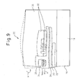
- Fig. 9 is a view illustrating a thermal deformation of a magnetic head structure according to the prior art and illustrating the principle of the present invention.
- the constituent elements of the magnetic head structure are represented by reference numerals identical to those of Fig. 3.
- the volume of the insulating layer 32 of Fig. 9 is smaller than that of the insulating layer 32 of Fig. 3.
- Fig. 9 is a view in which the thermal deformation is calculated, using the definite element method.
- a thermal deformation occurs, due to mainly the difference between the coefficient of thermal expansion of the insulating layer 32 and that of the protective layer 34.
- the deformation occurs such that a portion 16A of the floating surface 16 near the magnetic pole 26 protrudes to the greatest degree toward the disk 12, as shown by the arrow A.
- the amount of the floating of the magnetic head slider 14 is about ten and several nm, and if the amount of the protrusion of the portion 16A becomes greater, it can be said that the minimum amount of the floating of the magnetic head slider 14 is substantially reduced, and the portion 16A of the floating surface 16 where the coil 22 is positioned may contact the disk 12.
- the protective layer 34 is deformed in a manner as shown by the broken line in Fig. 9, by increasing the volume of the insulating layer more than a certain value, and it is possible to reduce the protrusion of the portion 16A of the floating surface 16 near the magnetic pole 26 in the direction shown by the arrow A. Therefore, the reliability of the operation of the magnetic head structure 20 is further improved.
- the amount of the thermal expansion of the insulating layer 32 may increase when the volume of the insulating layer 32 is increased, so that the amount of the protrusion of the portion 16A of the floating surface 16 near the magnetic pole 26 will be increased.
- the inventors of the present application have found that the expansion of the insulating layer 32 in the high temperature state occurs not only in the direction toward the floating surface 16 but also in the direction transverse to the floating surface 16.
- the volume of the insulating layer 32 having a greater coefficient of thermal expansion it is possible to reduce the protrusion of the portion 16A of the floating surface 16 near the magnetic pole 26 toward the disk 12. Also, it is necessary to increase the volume of the material of the insulating layer 32, as the thickness of the protective layer 34 covering the insulating layer 32 is greater, in order to deform the protective layer 34 so as to reduce the protrusion of the portion 16A of the floating surface 16 near the magnetic pole 26 toward the disk 12.
- Fig. 10 is a view illustrating the relationship between the volume of the insulating layer 32 (insulator volume) and the displacement of the portion 16A of the floating surface 16 near the magnetic pole 26 (displacement of point A) when the thickness of the protective layer 34 is changed.
- the displacement of the portion 16A is the amount of the protrusion, measured in the direction of the arrow A in Fig. 9.
- the thicknesses of the protective layer 32 are 6.25 ⁇ m, 12.5 ⁇ m, and 25 ⁇ m. From the result shown in Fig. 10, it will be understood that the amount of the protrusion of the portion 16A has a local minimum value at a certain value of the volume of the protective layer 34. Also, the local minimum value of the protrusion of the portion 16A shifts to the side where the volume of the protective layer 34 becomes greater, as the thickness of the protective layer 34 is greater.
- the characteristic feature of the present invention is to aim for a reduction of the amount of the protrusion of the portion 16A, using this mechanism.
- the volume of the insulating layer (photoresist) 32 is too large, the effect of reducing the amount of the protrusion of the portion 16A cannot be expected, and it is important to set the volume of the insulating layer 32 within the certain range including the local minimum value, in accordance with the thickness of the protective layer 34.
- the volume of the insulating layer 32 is in the range of 10 times to 40 times of a value defined by the cube of L, where L is the thickness of the protective layer 34 and is smaller than 25 ⁇ m
- the thickness L is a thickness of a portion of the protective layer 34 above the magnetic pole 26, as shown in Fig. 3. Note that this result is optimum in the magnetic head structure 20 in which the thickness of the protective layer 34 is smaller than 25 ⁇ m.
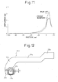
- Fig. 11 is a view illustrating the displacement of the portion of the floating surface of the present invention and that of the prior art.
- the magnetic head structure 20 of the present invention is constructed such that the thickness of the protective layer 34 is 12.5 ⁇ m and the volume of the insulating layer 32 is 3.26E-05 mm 3 .
- the conventional magnetic head structure is constructed such that the thickness of the protective layer 34 is 12.5 ⁇ m and the volume of the insulating layer 32 is 2.85E-06 mm 3 (standard volume of the insulating layer arranged around the coil 22). According to the present invention, the amount of the protrusion of the portion 16A is reduced by approximately 30%.
- Figs. 4 to 8 show examples of the magnetic head structure in which the material of the insulating layer 32 is differently arranged and the volume of the insulating layer 32 is increased.
- Fig. 4 is a cross-sectional view of the magnetic head structure.
- the volume of the upper part of the insulating layer 32 surrounding the upper coil 22U is increased, and the volume of the lower part of the insulating layer 32 surrounding the lower coil 22L is maintained unchanged with respect to the conventional one.
- Fig. 5 is a cross-sectional view of the magnetic head structure.
- the volume of the upper part of the insulating layer 32 surrounding the upper coil 22U is maintained unchanged with respect to the conventional one, and the volume of the lower part of the insulating layer 32 surrounding the lower coil 22L is increased.
- Fig. 6 is a cross-sectional view of the magnetic head structure.
- the volume of the upper part of the insulating layer 32 surrounding the upper coil 22U and the volume of the lower part of the insulating layer 32 surrounding the lower coil 22L are maintained unchanged with respect to conventional ones, and an additional insulating layer 32A is provided in a plane substantially coplanar with the plane of the insulating layer 32.
- Fig. 7 is a cross-sectional view of the magnetic head structure.
- the volume of the upper part of the insulating layer 32 surrounding the upper coil 22U and the volume of the lower part of the insulating layer 32 surrounding the lower coil 22L are maintained unchanged with respect to the conventional ones, and an additional insulating layer 32B is provided above the insulating layer 32.
- the additional insulating layer 32A or 32B does not directly insulate the coil 22, but is made from the same material as the insulating layer 32 and has the effect similar to that when the volume of the insulating layer 32 is increased.
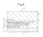
- Fig. 8 is a cross-sectional view of the magnetic head structure.
- the single layer coil 22 is provided, and the volume of the single layer insulating layer 32 surrounding the coil 22U is increased.
- the single layer coil 22 too, an effect similar to that of the multi-layered coil 22 is obtained.
- Fig. 12 is a view illustrating the upper coil of the two-layered coil
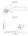
- Fig. 13 is a view illustrating the lower coil of the two-layered coil.
- the inner end of the upper coil 22U and the inner end of the lower coil 22L are connected to each other.
- the upper coil 22U and the lower coil 22L of Figs. 12 and 13 can be used as the upper coil 22U and the lower coil 22L of Figs. 3 to 7, or they can be used as the conventional two-layered coil.
- Each of the upper coil 22U and the lower coil 22L has a connecting line 22a and a coil portion 22b.
- the coil portion 22b has an outer coil part 22i and an outer coil part 22o.
- Each of the upper coil 22U and the lower coil 22L is formed such that the width W of the outer coil part 22o is greater than two times of the width w of the inner coil part 22i.
- the width of a portion 22n of the connecting line 22a near the outer coil part 22o is greater than the width of the outer coil part 22o.
- the width of a portion 22n of the connecting line 22a near the outer coil part 22o is greater than the width of other portion 22p of the connecting line 22a.
- the coil 22 has a wider portion (the outer coil part 22o), and the resistance of the coil 22 is reduced.
- the resistance of the coil 22 is reduced, the amount of the heat generated by the coil 22 is reduced and, as a result, the amount of the expansion of the insulating layer 32 is reduced and the thermal deformation of the magnetic head structure 20 is also reduced. Therefore, it is possible to reduce the protrusion of the portion 16A of the floating surface 16 at which the coil 22 is positioned (see Fig. 9).
- the coil 22 when an electric current is supplied to the coil 22, the coil 22 generates heat due to the resistance thereof, the temperature rises and, as a result, the portion 16A protrudes.
- the amount of the protrusion of the portion 16A when an electric current is supplied to the coil 22 is proportional to the amount of the generated heat (temperature rise). Therefore, the reduction of the resistance of the coil 22 leads to the reduction of the amount of the generated heat, i.e., to the reduction of the amount of the protrusion.
- the resistance of the coil 22 is reduced, by adopting such a structure that the connecting line 22a and the outer coil part 22o of the coil 22 are widely spread.
- the width of the outer coil part 22o is greater than two times of the width of the inner coil part 22i, and the size of the connecting line 22a is maintained substantially constant from its leading end to a position near the connecting point to the outer coil part 22o, and the size of the connecting line 22a is enlarged at a position just before the connecting point to the outer coil part 22o.
- Fig. 14 is a view illustrating the displacement of the portion of the floating surface of the present invention and that of the prior art.
- Fig. 15 is a cross-sectional view illustrating the magnetic head structure according to another embodiment of the present invention.
- the magnetic head structure 20 of this embodiment has a coil 22, a magnetic pole 26 allowing a magnetic flux generated by the coil 22 to be transmitted therethrough and forming a magnetic gap 24, an insulating layer 32 surrounding the coil 22, and a protective layer 34 covering the insulating layer 32 and the magnetic pole 26.
- a two-layered shield 28 is arranged on the substrate 18 and a reading element (MR element) 30 is arranged between two layers of the shield 28.
- the coil 22 is formed on the substrate 18 via the shield 28 and a part of the protective layer 34.
- the magnetic head structure 20 comprises at least one material layer 36 arranged in or on the protective layer 34 and having coefficient of thermal expansion smaller than that of the protective layer 34.
- the material layer 36 having smaller coefficient of thermal expansion is preferably arranged in one continuous layer, rather than being discontinuously arranged in one layer.
- one material layer 36 having smaller coefficient of thermal expansion is arranged on the surface of the substrate 18.
- a part of the protective layer 34 is formed on the material layer 36 having smaller coefficient of thermal expansion
- the shield 28 is formed on the part of the protective layer 34.
- another one material layer 36 having smaller coefficient of thermal expansion is arranged on the surface of the protective layer 34.
- the material layer 36 having smaller coefficient of thermal expansion comprises Invar.
- the material layer 36 having smaller coefficient of thermal expansion comprises a material having smaller coefficient of thermal expansion such as aluminum nitride (A1N), or a composite structure of an insulating material and Invar.
- the thermal expansion of the material layer 36 having smaller coefficient of thermal expansion is small when the temperature rises because the amount of thermal expansion is small, and suppresses the thermal expansion of the insulating layer 32 in the direction perpendicular to the floating surface 16, whereby it is possible to reduce the protrusion of the portion 16A of the floating surface 16 near the magnetic pole. That is, by providing the material layer 36 having smaller coefficient of thermal expansion, the insulating layer 32 the amount of the thermal expansion of which is greater is prevented from expanding to the greater extent in the direction perpendicular to the floating surface 16, and the protrusion of of the portion 16A of the floating surface 16 near the magnetic pole is reduced. The insulating layer 32 can expand in the direction parallel to the floating surface 16.
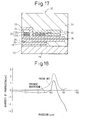
- Fig. 18 is a view illustrating the displacement of the portion of the floating surface of the present invention and that of the prior art. According to the embodiment of the present invention, the displacement (the amount of the protrusion) of of the portion 16A of the floating surface 16 near the magnetic pole is greatly reduced, compared with that of the prior art.
- Fig. 16 is a cross-sectional view illustrating a modified example of the magnetic head structure.
- the magnetic head structure of Fig. 16 is similar to that of Fig. 15, except for the material layer 36 having smaller coefficient of thermal expansion.
- the material layer 36 having smaller coefficient of thermal expansion is arranged within the protective layer.
- the operation and the effect of this example are similar to those of the example of Fig. 15.
- Fig. 17 is a cross-sectional view illustrating a modified example of the magnetic head structure.
- the magnetic head structure of Fig. 16 is similar to that of Fig. 15, except for the material layer 36 having smaller coefficient of thermal expansion.
- the material layer 36 having smaller coefficient of thermal expansion is arranged between the magnetic pole 26 and the upper shield 28.
- the operation and the effect of this example are similar to those of the example of Fig. 15.
- the material layer 36 having smaller coefficient of thermal expansion is arranged on the surface of the protective layer 34.
- the material layer 36 having smaller coefficient of thermal expansion is arranged within the protective layer.
- the material layers 36 having smaller coefficient of thermal expansion are arranged on the surface of the protective layer 34 and between the substrate 18 and the protective layer 34.
- the material layer 36 having smaller coefficient of thermal expansion is arranged on the surface of the protective layer 34 and between the magnetic pole 26 and the shield 28.
- the material layer 36 having smaller coefficient of thermal expansion is arranged at any position within the protective layer 34 as a layer parallel to the insulating layer 32.
Landscapes
- Engineering & Computer Science (AREA)
- Manufacturing & Machinery (AREA)
- Physics & Mathematics (AREA)
- Electromagnetism (AREA)
- Magnetic Heads (AREA)
Abstract
Description
Also, it is necessary to increase the volume of the material of the insulating layer as the thickness of the protective layer covering the insulating layer is greater, in order to deform the protective layer to reduce the protrusion of a portion of a floating surface near a magnetic pole toward a disk.
| No Coil Enlargement | Coil Enlargement | |
| Resistance (Ω) | 3.0 | 2.4 |
| Amount of Generated Heat (mW) | 10.8 | 8.6 |
| Maximum Rising Temperature (°C) | 13.0 | 10.3 |
Claims (10)
- A magnetic head structure comprising:wherein the insulating layer has a volume equal to or greater than a value which is determined with respect to a thickness of the protective layer.a coil;a magnetic pole allowing a magnetic flux generated by the coil to be transmitted therethrough and forming a magnetic gap;an insulating layer surrounding the coil; anda protective layer covering the insulating layer and the magnetic pole;
- The magnetic head structure according to claim 1, wherein the volume of the insulating layer is in the range of 10 times to 40 times of a value defined by the cube of L, where L is the thickness of the protective layer and is smaller than 25 µm.
- The magnetic head structure according to claim 1, wherein the insulating layer comprises a layer surrounding the coil and a layer arranged differently from the layer surrounding the coil.
- A magnetic head structure comprising:wherein the coil has an inner coil part and an outer coil part, and a width of the outer coil part is greater than two times of a width of the inner coil part.a coil;a magnetic pole allowing a magnetic flux generated by the coil to be transmitted therethrough and forming a magnetic gap;an insulating layer surrounding the coil; anda protective layer covering the insulating layer and the magnetic pole;
- The magnetic head structure according to claim 4, wherein the coil has a connecting line, and a width of a portion of the connecting line near the outer coil part is greater than the width of the outer coil part.
- A magnetic head structure comprising:a coil;a magnetic pole allowing a magnetic flux generated by the coil to be transmitted therethrough and forming a magnetic gap;an insulating layer surrounding the coil;a protective layer covering the insulating layer and the magnetic pole; anda material layer arranged in or on the protective layer and having coefficient of thermal expansion smaller than that of the protective layer.
- The magnetic head structure according to claim 6, wherein the material layer having coefficient of thermal expansion smaller than that of the protective layer is arranged on the protective layer.
- The magnetic head structure according to claim 6, wherein the material layer having coefficient of thermal expansion smaller than that of the protective layer is arranged in the protective layer.
- The magnetic head structure according to claim 6, wherein the material layer having coefficient of thermal expansion smaller than that of the protective layer is arranged between the magnetic pole and a shield.
- The magnetic head structure according to claim 6, wherein the material layers having coefficient of thermal expansion smaller than that of the protective layer are arranged on the protective layer, in the protective layer and between the magnetic pole and a shield.
Applications Claiming Priority (2)
| Application Number | Priority Date | Filing Date | Title |
|---|---|---|---|
| JP2004099055 | 2004-03-30 | ||
| JP2004099055A JP2005285236A (en) | 2004-03-30 | 2004-03-30 | Magnetic head structure |
Publications (2)
| Publication Number | Publication Date |
|---|---|
| EP1583077A2 true EP1583077A2 (en) | 2005-10-05 |
| EP1583077A3 EP1583077A3 (en) | 2007-07-25 |
Family
ID=34879965
Family Applications (1)
| Application Number | Title | Priority Date | Filing Date |
|---|---|---|---|
| EP05251780A Withdrawn EP1583077A3 (en) | 2004-03-30 | 2005-03-23 | Magnetic head structure with enlarged insulating layer |
Country Status (5)
| Country | Link |
|---|---|
| US (3) | US7414810B2 (en) |
| EP (1) | EP1583077A3 (en) |
| JP (1) | JP2005285236A (en) |
| KR (1) | KR100733442B1 (en) |
| CN (3) | CN101034554A (en) |
Cited By (1)
| Publication number | Priority date | Publication date | Assignee | Title |
|---|---|---|---|---|
| EP1705646A1 (en) | 2005-03-23 | 2006-09-27 | Fujitsu Limited | Magnetic head structure |
Families Citing this family (11)
| Publication number | Priority date | Publication date | Assignee | Title |
|---|---|---|---|---|
| JP4226976B2 (en) * | 2003-08-29 | 2009-02-18 | Tdk株式会社 | Thin film magnetic head and magnetic recording apparatus |
| US20060221498A1 (en) * | 2005-03-30 | 2006-10-05 | Hitachi Global Storage Technologies Netherlands, B.V | Head design with low coefficient of thermal expansion insert layer |
| JP2007213749A (en) * | 2006-02-13 | 2007-08-23 | Fujitsu Ltd | Thin film magnetic head |
| JP2007323761A (en) | 2006-06-02 | 2007-12-13 | Tdk Corp | Thin-film magnetic head equipped with coil insulating layer with regulated coefficient of thermal expansion and young's modulus |
| JP2008077719A (en) | 2006-09-20 | 2008-04-03 | Alps Electric Co Ltd | Thin-film magnetic head |
| US8222087B2 (en) | 2006-12-19 | 2012-07-17 | HGST Netherlands, B.V. | Seed layer for a heat spreader in a magnetic recording head |
| JP2009099219A (en) * | 2007-10-17 | 2009-05-07 | Fujitsu Ltd | Magnetic head |
| US8031432B2 (en) * | 2007-12-12 | 2011-10-04 | Hitachi Global Storage Technologies Netherlands B.V. | Magnetic write head having helical coil with a fin structure for reduced heat induced protrusion |
| JP5826987B2 (en) | 2008-12-19 | 2015-12-02 | エイチジーエスティーネザーランドビーブイ | Magnetic head slider |
| JP2010238314A (en) | 2009-03-31 | 2010-10-21 | Toshiba Storage Device Corp | Magnetic head and information storage device |
| JP2016054013A (en) * | 2014-09-03 | 2016-04-14 | 株式会社東芝 | Magnetic head and magnetic disk device |
Family Cites Families (28)
| Publication number | Priority date | Publication date | Assignee | Title |
|---|---|---|---|---|
| JPS58128012A (en) * | 1982-01-27 | 1983-07-30 | Hitachi Ltd | Thin film magnetic head and its manufacture |
| JPS63108516A (en) | 1986-10-24 | 1988-05-13 | Yamaha Corp | Structure of protecting film for thin film magnetic head |
| JPH01109507A (en) * | 1987-10-23 | 1989-04-26 | Hitachi Ltd | Thin film coil for magnetic head |
| US5173826A (en) * | 1991-06-03 | 1992-12-22 | Read-Rite Corp. | Thin film head with coils of varying thickness |
| JPH04366411A (en) * | 1991-06-13 | 1992-12-18 | Ngk Insulators Ltd | Thin-film magnetic head |
| US6166880A (en) * | 1991-08-13 | 2000-12-26 | Tdk Corporation | Thin film magnetic head which prevents errors due to electric discharge |
| US5949627A (en) * | 1993-02-19 | 1999-09-07 | Read-Rite Corporation | Thin film magnetic head with stress relief layering |
| JPH0757217A (en) * | 1993-08-10 | 1995-03-03 | Fuji Elelctrochem Co Ltd | Thin film magnetic head |
| US5710683A (en) * | 1996-04-18 | 1998-01-20 | Storage Technology Corporation | Thin film tape head with substrate for reduced pole-tip recession |
| JPH117608A (en) * | 1997-04-25 | 1999-01-12 | Fujitsu Ltd | Magnetic head and method of manufacturing the same |
| JP2000132803A (en) | 1998-10-23 | 2000-05-12 | Yamaha Corp | Optic-magnetro-optical head |
| JP3349975B2 (en) * | 1999-01-13 | 2002-11-25 | アルプス電気株式会社 | Thin film magnetic head and method of manufacturing the same |
| JP2000268321A (en) | 1999-03-18 | 2000-09-29 | Alps Electric Co Ltd | Thin film magnetic head |
| JP3920496B2 (en) | 1999-04-16 | 2007-05-30 | 株式会社東芝 | Magnetic head and magnetic disk device using the same |
| JP2000306215A (en) * | 1999-04-16 | 2000-11-02 | Toshiba Corp | Magnetic head and magnetic disk drive using the same |
| JP3455155B2 (en) * | 1999-06-28 | 2003-10-14 | アルプス電気株式会社 | Thin film magnetic head and method of manufacturing the same |
| JP3599235B2 (en) * | 1999-07-19 | 2004-12-08 | Tdk株式会社 | Thin-film magnetic head, magnetic head device, and magnetic disk device |
| CN1246829C (en) | 2000-06-20 | 2006-03-22 | 西加特技术有限责任公司 | Disc drive with layered write coil |
| JP2002123910A (en) * | 2000-10-16 | 2002-04-26 | Alps Electric Co Ltd | Thin-film magnetic head, and its manufacturing method |
| JP2003091802A (en) | 2001-09-18 | 2003-03-28 | Alps Electric Co Ltd | Thin film magnetic head |
| JP3636133B2 (en) | 2001-11-29 | 2005-04-06 | Tdk株式会社 | Thin film magnetic head, head gimbal assembly including the thin film magnetic head, and magnetic disk apparatus including the head gimbal assembly |
| US6977796B2 (en) * | 2002-02-08 | 2005-12-20 | Headway Technologies, Inc. | Wiring pattern and method of manufacturing the same and thin film magnetic head and method of manufacturing the same |
| US7035046B1 (en) * | 2002-03-19 | 2006-04-25 | Western Digital (Fremont), Inc. | System and method for minimizing thermal pole tip protrusion |
| US7092208B2 (en) * | 2002-07-11 | 2006-08-15 | Seagate Technology Llc | Magnetic transducers with reduced thermal pole-tip protrusion/recession |
| US6989963B2 (en) * | 2002-09-13 | 2006-01-24 | Seagate Technology Llc | Writer core structures having improved thermal dissipation properties |
| US6980395B2 (en) * | 2002-10-31 | 2005-12-27 | International Business Machines Corporation | Enhanced coplanar conductance structure for inductive heads |
| US6950279B2 (en) | 2003-01-30 | 2005-09-27 | Headway Technologies, Inc. | Thin-film magnetic head with thin-film coil of low resistance |
| US7085099B2 (en) * | 2004-01-20 | 2006-08-01 | Headway Technologies, Inc. | Thin film magnetic head having spiral coils and manufacturing method thereof |
-
2004
- 2004-03-30 JP JP2004099055A patent/JP2005285236A/en active Pending
- 2004-08-25 US US10/925,564 patent/US7414810B2/en not_active Expired - Fee Related
-
2005
- 2005-03-23 EP EP05251780A patent/EP1583077A3/en not_active Withdrawn
- 2005-03-28 CN CNA2007100883508A patent/CN101034554A/en active Pending
- 2005-03-28 CN CNA2007100883512A patent/CN101038746A/en active Pending
- 2005-03-28 CN CNB2005100588264A patent/CN100339888C/en not_active Expired - Fee Related
- 2005-03-30 KR KR1020050026585A patent/KR100733442B1/en not_active Expired - Fee Related
-
2007
- 2007-02-07 US US11/703,447 patent/US20070165329A1/en not_active Abandoned
- 2007-02-07 US US11/703,503 patent/US20070133126A1/en not_active Abandoned
Cited By (1)
| Publication number | Priority date | Publication date | Assignee | Title |
|---|---|---|---|---|
| EP1705646A1 (en) | 2005-03-23 | 2006-09-27 | Fujitsu Limited | Magnetic head structure |
Also Published As
| Publication number | Publication date |
|---|---|
| JP2005285236A (en) | 2005-10-13 |
| US20050219749A1 (en) | 2005-10-06 |
| CN101038746A (en) | 2007-09-19 |
| EP1583077A3 (en) | 2007-07-25 |
| US7414810B2 (en) | 2008-08-19 |
| US20070133126A1 (en) | 2007-06-14 |
| CN1677497A (en) | 2005-10-05 |
| US20070165329A1 (en) | 2007-07-19 |
| KR20060045015A (en) | 2006-05-16 |
| CN100339888C (en) | 2007-09-26 |
| CN101034554A (en) | 2007-09-12 |
| KR100733442B1 (en) | 2007-06-29 |
Similar Documents
| Publication | Publication Date | Title |
|---|---|---|
| US20070133126A1 (en) | Magnetic head structure with enlarged insulating layer | |
| US8810962B2 (en) | Insertion under read shield for improved read gap actuation in dynamic flying height | |
| US7110219B2 (en) | Flying type thin-film magnetic head | |
| US6813118B2 (en) | Transducing head having improved studs and bond pads to reduce thermal deformation | |
| US8159782B2 (en) | Thin film magnetic head having heating element | |
| US20090103208A1 (en) | Magnetic head | |
| US8045293B2 (en) | Thin film magnetic head including thermal deformation-preventing layer | |
| US6922311B2 (en) | Thin film magnetic head including coil insulated by organic and inorganic insulating materials | |
| US7733606B2 (en) | Thin film magnetic head with thermal flying height control pads located at both ends of all pads series on slider side plane | |
| US7123447B2 (en) | Patterned multi-material basecoat to reduce thermal protrusion | |
| US7061726B2 (en) | Thin film magnetic head | |
| US7259939B2 (en) | Thin-film magnetic head including a toroidal coil layer and connecting layer formed between a first and second magnetic cores disposed at a back side of the toroidal coil layer | |
| US7212378B2 (en) | Thin film magnetic head having toroidal coil | |
| US7346978B2 (en) | Process of making a thin film magnetic head | |
| US7382579B2 (en) | Magnetic head structure | |
| US8174791B2 (en) | Magnetic head and information storage device | |
| US7738216B2 (en) | Thin film magnetic head having a thermal plastic deformation portion and manufacturing the same | |
| US7262940B2 (en) | Separate read/write magnetic head | |
| US11735212B1 (en) | Thermally assisted magnetic head including a record/read separate protective structure, head gimbal assembly and hard disk drive each having the thermally assisted magnetic head | |
| US6898056B2 (en) | Thin-film magnetic head capable of suppressing side fringing | |
| JP2008004261A (en) | Thin film magnetic head | |
| JPH11232612A (en) | Composite magnetic head |
Legal Events
| Date | Code | Title | Description |
|---|---|---|---|
| PUAI | Public reference made under article 153(3) epc to a published international application that has entered the european phase |
Free format text: ORIGINAL CODE: 0009012 |
|
| AK | Designated contracting states |
Kind code of ref document: A2 Designated state(s): AT BE BG CH CY CZ DE DK EE ES FI FR GB GR HU IE IS IT LI LT LU MC NL PL PT RO SE SI SK TR |
|
| AX | Request for extension of the european patent |
Extension state: AL BA HR LV MK YU |
|
| RIC1 | Information provided on ipc code assigned before grant |
Ipc: G11B 5/31 20060101ALI20060616BHEP Ipc: G11B 5/60 20060101ALI20060616BHEP Ipc: G11B 5/127 20060101AFI20050630BHEP |
|
| PUAL | Search report despatched |
Free format text: ORIGINAL CODE: 0009013 |
|
| AK | Designated contracting states |
Kind code of ref document: A3 Designated state(s): AT BE BG CH CY CZ DE DK EE ES FI FR GB GR HU IE IS IT LI LT LU MC NL PL PT RO SE SI SK TR |
|
| AX | Request for extension of the european patent |
Extension state: AL BA HR LV MK YU |
|
| 17P | Request for examination filed |
Effective date: 20080121 |
|
| AKX | Designation fees paid |
Designated state(s): DE FR GB |
|
| 17Q | First examination report despatched |
Effective date: 20080408 |
|
| RAP1 | Party data changed (applicant data changed or rights of an application transferred) |
Owner name: TOSHIBA STORAGE DEVICE CORPORATION |
|
| STAA | Information on the status of an ep patent application or granted ep patent |
Free format text: STATUS: THE APPLICATION IS DEEMED TO BE WITHDRAWN |
|
| 18D | Application deemed to be withdrawn |
Effective date: 20111001 |