EP1582962A2 - Methods and systems for protecting media content - Google Patents
Methods and systems for protecting media content Download PDFInfo
- Publication number
- EP1582962A2 EP1582962A2 EP05101873A EP05101873A EP1582962A2 EP 1582962 A2 EP1582962 A2 EP 1582962A2 EP 05101873 A EP05101873 A EP 05101873A EP 05101873 A EP05101873 A EP 05101873A EP 1582962 A2 EP1582962 A2 EP 1582962A2
- Authority
- EP
- European Patent Office
- Prior art keywords
- playback application
- media playback
- component
- content protection
- status
- Prior art date
- Legal status (The legal status is an assumption and is not a legal conclusion. Google has not performed a legal analysis and makes no representation as to the accuracy of the status listed.)
- Granted
Links
Images



Classifications
-
- G—PHYSICS
- G06—COMPUTING OR CALCULATING; COUNTING
- G06F—ELECTRIC DIGITAL DATA PROCESSING
- G06F21/00—Security arrangements for protecting computers, components thereof, programs or data against unauthorised activity
- G06F21/60—Protecting data
- G06F21/606—Protecting data by securing the transmission between two devices or processes
-
- H—ELECTRICITY
- H04—ELECTRIC COMMUNICATION TECHNIQUE
- H04M—TELEPHONIC COMMUNICATION
- H04M1/00—Substation equipment, e.g. for use by subscribers
- H04M1/02—Constructional features of telephone sets
- H04M1/04—Supports for telephone transmitters or receivers
- H04M1/05—Supports for telephone transmitters or receivers specially adapted for use on head, throat or breast
-
- G—PHYSICS
- G06—COMPUTING OR CALCULATING; COUNTING
- G06F—ELECTRIC DIGITAL DATA PROCESSING
- G06F21/00—Security arrangements for protecting computers, components thereof, programs or data against unauthorised activity
- G06F21/10—Protecting distributed programs or content, e.g. vending or licensing of copyrighted material ; Digital rights management [DRM]
-
- H—ELECTRICITY
- H04—ELECTRIC COMMUNICATION TECHNIQUE
- H04N—PICTORIAL COMMUNICATION, e.g. TELEVISION
- H04N21/00—Selective content distribution, e.g. interactive television or video on demand [VOD]
- H04N21/40—Client devices specifically adapted for the reception of or interaction with content, e.g. set-top-box [STB]; Operations thereof
- H04N21/41—Structure of client; Structure of client peripherals
- H04N21/4104—Peripherals receiving signals from specially adapted client devices
- H04N21/4122—Peripherals receiving signals from specially adapted client devices additional display device, e.g. video projector
-
- H—ELECTRICITY
- H04—ELECTRIC COMMUNICATION TECHNIQUE
- H04N—PICTORIAL COMMUNICATION, e.g. TELEVISION
- H04N21/00—Selective content distribution, e.g. interactive television or video on demand [VOD]
- H04N21/40—Client devices specifically adapted for the reception of or interaction with content, e.g. set-top-box [STB]; Operations thereof
- H04N21/43—Processing of content or additional data, e.g. demultiplexing additional data from a digital video stream; Elementary client operations, e.g. monitoring of home network or synchronising decoder's clock; Client middleware
- H04N21/436—Interfacing a local distribution network, e.g. communicating with another STB or one or more peripheral devices inside the home
- H04N21/4367—Establishing a secure communication between the client and a peripheral device or smart card
-
- H—ELECTRICITY
- H04—ELECTRIC COMMUNICATION TECHNIQUE
- H04N—PICTORIAL COMMUNICATION, e.g. TELEVISION
- H04N21/00—Selective content distribution, e.g. interactive television or video on demand [VOD]
- H04N21/40—Client devices specifically adapted for the reception of or interaction with content, e.g. set-top-box [STB]; Operations thereof
- H04N21/43—Processing of content or additional data, e.g. demultiplexing additional data from a digital video stream; Elementary client operations, e.g. monitoring of home network or synchronising decoder's clock; Client middleware
- H04N21/44—Processing of video elementary streams, e.g. splicing a video clip retrieved from local storage with an incoming video stream or rendering scenes according to encoded video stream scene graphs
- H04N21/4405—Processing of video elementary streams, e.g. splicing a video clip retrieved from local storage with an incoming video stream or rendering scenes according to encoded video stream scene graphs involving video stream decryption
-
- H—ELECTRICITY
- H04—ELECTRIC COMMUNICATION TECHNIQUE
- H04N—PICTORIAL COMMUNICATION, e.g. TELEVISION
- H04N21/00—Selective content distribution, e.g. interactive television or video on demand [VOD]
- H04N21/40—Client devices specifically adapted for the reception of or interaction with content, e.g. set-top-box [STB]; Operations thereof
- H04N21/43—Processing of content or additional data, e.g. demultiplexing additional data from a digital video stream; Elementary client operations, e.g. monitoring of home network or synchronising decoder's clock; Client middleware
- H04N21/443—OS processes, e.g. booting an STB, implementing a Java virtual machine in an STB or power management in an STB
- H04N21/4431—OS processes, e.g. booting an STB, implementing a Java virtual machine in an STB or power management in an STB characterized by the use of Application Program Interface [API] libraries
-
- H—ELECTRICITY
- H04—ELECTRIC COMMUNICATION TECHNIQUE
- H04N—PICTORIAL COMMUNICATION, e.g. TELEVISION
- H04N21/00—Selective content distribution, e.g. interactive television or video on demand [VOD]
- H04N21/80—Generation or processing of content or additional data by content creator independently of the distribution process; Content per se
- H04N21/83—Generation or processing of protective or descriptive data associated with content; Content structuring
- H04N21/835—Generation of protective data, e.g. certificates
-
- H—ELECTRICITY
- H04—ELECTRIC COMMUNICATION TECHNIQUE
- H04R—LOUDSPEAKERS, MICROPHONES, GRAMOPHONE PICK-UPS OR LIKE ACOUSTIC ELECTROMECHANICAL TRANSDUCERS; ELECTRIC HEARING AIDS; PUBLIC ADDRESS SYSTEMS
- H04R1/00—Details of transducers, loudspeakers or microphones
- H04R1/10—Earpieces; Attachments therefor ; Earphones; Monophonic headphones
-
- H—ELECTRICITY
- H04—ELECTRIC COMMUNICATION TECHNIQUE
- H04R—LOUDSPEAKERS, MICROPHONES, GRAMOPHONE PICK-UPS OR LIKE ACOUSTIC ELECTROMECHANICAL TRANSDUCERS; ELECTRIC HEARING AIDS; PUBLIC ADDRESS SYSTEMS
- H04R5/00—Stereophonic arrangements
- H04R5/033—Headphones for stereophonic communication
- H04R5/0335—Earpiece support, e.g. headbands or neckrests
Definitions
- This invention relates to methods and systems for protecting media content.
- Content providers such as those that provide audio and/or video data in the form of data streams, application vendors that provide applications to render such data, and others often desire to protect such data from being ascertained, used or otherwise rendered by unauthorized entities. Such protection is typically desired from the point where the data resides, in some protected form and on some type of readable medium, along the chain of components that will handle or otherwise process such data, up to and including both the physical output connector that provides the data to a device such as a display or speakers, as well as these devices themselves.
- FIG. 1 illustrates, at a high level, an exemplary system 10 into which protected content 12, e.g. compressed and encrypted content, can be received and processed.
- protected content 12 is provided into a consumer device 14 such as a personal computer.
- an application 16 typically processes the protected content by, for example, using a decryption component 18 to decrypt the content and a decoder component 20 to decode or decompress the content.
- a decryption component 18 to decrypt the content
- a decoder component 20 to decode or decompress the content.
- the processed content is provided to a renderer component 22 which then ensures that the data is provided to a device, such as a display 24 (in the case of video data) and/or speakers 26 (in the case of audio data).
- the data in order for the data to get to the appropriate hardware device such as the display or speaker, the data has to transit some type of bus, such as a PCI/AGP bus, and then has to travel through a physical connector and over a cable, such as an S-Video cable or a DVI cable.
- some type of bus such as a PCI/AGP bus
- the application typically does not communicate directly to the hardware that is to render the data. Rather, there is typically a software stack in the user mode with which the application communicates, and then a driver stack in the kernel mode below the user mode software stack that actually communicates with the hardware. Effectively, any one of these components in the chain can actually tamper with the data and/or communications being passed along the chain.
- this invention arose out of concerns associated with providing secure channels for both communications and data to flow from the application to downstream components.
- Various embodiments pertain to methods and systems that utilize a protocol which enables media content protection by establishing a secure communication channel and, in some embodiments, a secure data channel, between a device such as a computer running a protected content playback application, and an associated driver, such as a graphics driver, of an associated display device such as a monitor, flat panel LCD, television and the like.
- Various embodiments are directed to addressing the needs of content providers and application vendors to signal that content protection should be applied to data that is output over a physical connector to a device such as a display device.
- the various embodiments described below provide a means for securely passing commands from a user mode playback application to a driver, such as a graphics driver, and securely returning status information from the driver to the user mode application.
- a driver such as a graphics driver
- the user mode application can instruct an associated driver to enable content output protection on the physical connector between the computer and the display device.
- Exclusivity of the secure channel session can prevent attackers from recording the protected content as it is transmitted from the computer to the display.
- At least some embodiments are described that can be used to provide a secure signaling mechanism from an application to various downstream components so that the application can communicate which of a potential number of content protection technologies should be applied, and how at least some of those content protection technologies should be applied to protect media content output.
- at least some of the embodiments are agnostic with respect to the type of content protection technology that is used to protect the media output. This is advantageous in that the described system and protocol are adaptively flexible and be used in connection with many different types of current and future content protection technologies, as will become apparent below.
- FIG. 2 shows a computing system in the form of a consumer device 200.
- Consumer device 200 can comprise any suitable type of consumer device that can be utilized to render protected media content.
- One example of such a device is a personal computer.
- Other types of devices can include personal video recorder (PVR) devices, digital video recorder (DVR) devices and the like.
- Consumer device 200 comprises a playback application 202 that can acquire protected media content from a protected media content source, system software 204 that facilitates processing of the protected media content, and driver software 206 (or the software representation of associated hardware) that is utilized to interface with hardware 208 (such as a video card) that provides the processed media content over some type of physical connector 210 to an associated output device 212 over which the media content is rendered for a user.
- driver software 206 or the software representation of associated hardware
- hardware 208 such as a video card
- Examples of output devices include display devices and speakers, as noted above.
- various different types of content protection technologies that can be utilized to protect the media content between the physical connector 210 and the output device 212.
- various content protection types can include Analog Content Protection (ACP), Copy Generation Management System - Analog (CGMS-A), and High-bandwidth Digital Content Protection (HDCP), as will be appreciated by the skilled artisan.
- ACP Analog Content Protection
- CGMS-A Copy Generation Management System - Analog
- HDCP High-bandwidth Digital Content Protection
- a secure link or channel is established between application 202 and one or more downstream components.
- two different secure channels are illustrated, although only one channel of either type need be implemented.
- a secure communication channel 216 is established between application 202 and driver software 206.
- a secure channel 218 is established between application 202 and hardware 208.
- channel 216 can be utilized primarily for communication between the application and the driver. Such communication can include communicating commands, status requests and associated statuses between the application and the driver. Channel 218 can be used not only for this type of communication, but for providing the actual media data, such as audio and video data, to the hardware.
- a command is an instruction and can comprise, among other characteristics, the following characteristics.
- a command can alter or otherwise impact the configuration of the hardware 208. Alternately or additionally, a command can signal the hardware to process the media content in some specific way.
- a status request can effectively retrieve, from the hardware, two sets of information.
- a status request can retrieve information that pertains to any commands that were sent from the application to a downstream component. For example, if the application sent a command to perform some task-for example setting a particular type of content protection technology-an associated status request might retrieve information as to whether the task was performed.
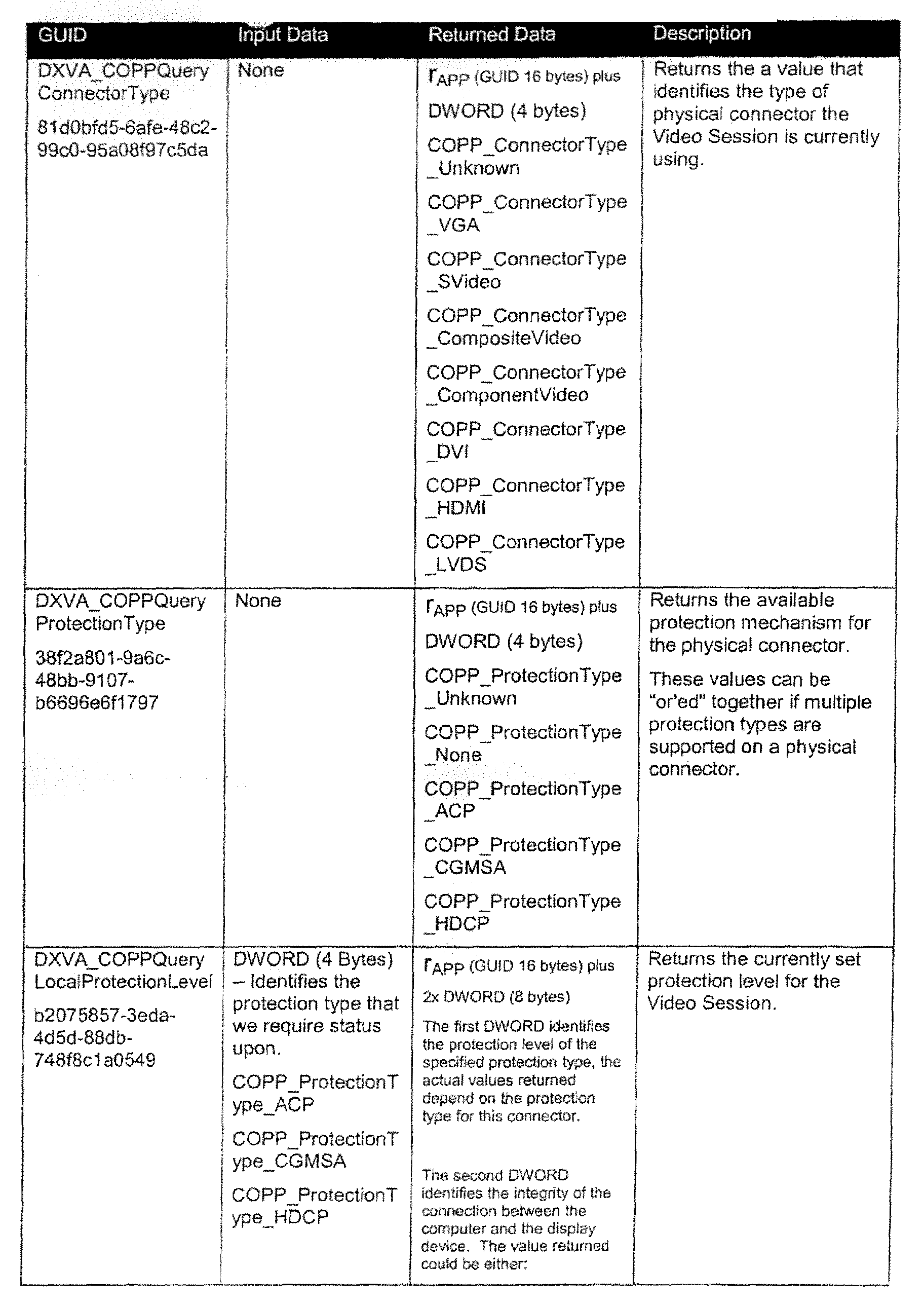
- a status request can retrieve information that is not necessarily associated with whether a command was sent. For example, a status request might retrieve additional hardware configuration information that might be intrinsic to a particular device, e.g. the type of physical connector that is being utilized. Such status requests can also be used to ascertain which content protection technologies are supported by the hardware for a particular physical connector.
- a physical connector may be a DVI connector, but there may not be HDCP support in the graphics hardware.
- the application might then make an intelligent choice to either play a down-sampled or lower resolution version of the video data or perhaps not play the video data at all.
- a one-way trust model and key transport protocol are utilized to establish trust between two endpoints of a communication chain.
- key transport carries with it a couple of advantages, as will be appreciated by the skilled artisan.
- Second, key transport provides the ability to do what is called "pass through”. Pass through can allow content data to be encrypted all of the way along the chain to the graphics hardware. This, in turn, can allow the graphics hardware to decrypt the content data, decode the content data into an associated surface, and then process the content data onto a display, as will be appreciated by the skilled artisan.
- a one-way authenticated channel is established between application 202 and driver software 206 using, for example, Public Key Infrastructure (PKI) techniques. More specifically, in this example, a channel key in the form of a data integrity key is established between application 202 and driver software 206. Once the channel key is established, commands and status messages can be passed unencrypted and message authentication codes or MACs can be created with the data integrity key.
- PKI Public Key Infrastructure
- application 202 To establish trust with a downstream component, application 202 first calls driver software 206 and receives from the driver software a random number r GH and a digital certificate Cert GH associated with the hardware 208 (Fig. 2). When the application 202 receives the digital certificate Cert GH , the application processes the certificate to verify that the signature on the digital certificate is provided by a trusted entity and to retrieve the public key (P GH ) of the driver software 206 (in the event channel 216 is utilized) or graphics hardware 208 (in the event channel 218 is utilized). The public key P GH can now be used by the application to encrypt data that can only be decrypted by an associated private key which is kept secure by the driver software or the graphics hardware. The process just described establishes trust between the application and the driver software.
- P GH public key
- application 202 concatenates the random number r GH provided by the driver software, a data integrity key k DI (also called a session key), a random starting status sequence number (status_start) and a random starting command sequence number (command_start), encrypts the concatenation of values using the public key P GH of the driver software, and sends the encrypted data to the driver software 206.
- k DI also called a session key
- status_start also called a session key
- command_start random starting command sequence number
- the random starting status sequence number (status_start) and random starting command sequence number (command_start) are utilized to ensure that if a particular message is lost, whether the message is a status request or a reported status (in the case of the starting status sequence number) or a command (in the case of the starting command sequence number), the intended message receiver can ascertain this fact. More specifically, each time a command is sent by the application, the random starting command sequence number is incremented by one. Similarly, each time a status message is sent, the sending entity increments the starting status sequence number by one. On the receiving end, the receiver of the message can ascertain whether a message has been lost by simply checking to see whether the sequence numbers occur in order. If there is a missing sequence number, then an associated message has been lost and appropriate action can be taken. In this manner, using random starting sequence numbers ensures the integrity and the order of the messages.
- command portion of the protocol enables the system's hardware, such as hardware 208 (Fig. 2), to be instructed by the application to turn on and in some instances configure a particular content protection technology such as HDCP or CGMS-A.
- command messages are contained in an envelope that has two sections: a data section and a message authentication code or MAC section.
- the data section of the command message contains a command and an associated command sequence number.
- the message authentication code or MAC section contains what can be considered as a keyed hash of the command and associated command sequence number.
- the key that is used to produce the keyed hash is the data integrity key k DI described above.
- MAC kDI Communication kDI
- the "MAC kDI (Command)" portion of the message comprises a MAC of the "Command” portion that was computed by the application.
- the driver software 206 can run the MAC algorithm over the command portion of the message using the negotiated session key k DI . Once the MAC algorithm has been run over the command portion of the command message, the driver software can compare this value with the MAC value received in the command message. If the two values compare favorably, then the integrity of the command message is established.
- Value Description Command Variable length command data.
- MAC kDI Communication Protocol 128-bit MAC of the command data and command sequence number using the data integrity session key k DI .
- status messages are contained in an envelope that has two sections: a data section and a message authentication code or MAC section.
- the message sender calculates a MAC of the status data using the session key k DI and an associated MAC algorithm.
- Fig. 5 As an example of how the status protocol can be implemented, consider Fig. 5. There, application 202 makes a request for status information in the form: r APP , Status Request where r APP is a random number generated by the application and "Status Request" is the actual request for status information.
- driver software 206 In response to receiving the status request from the application, driver software 206 ascertain whatever status information is appropriate and provides the status information, along with the appropriate status sequence number, into the data section of the envelope. In addition, the driver software also computes a MAC of the status information along with the random number provided by the application.
- the status message is then provided back to the application in the following form: r APP , Status, MAC kDI (r APP , Status) where "Status" includes not only the status information, but the status sequence number as well.
- the MAC kDI (r APP , Status) portion of the message comprises a MAC of the random number provided by the application and the status information.
- the application can compute a MAC of the random number and the status information by running the MAC algorithm over the random number and the status information and then can compare this value with the value in the MAC kDI (r APP , Status) section of the message. By doing this, the application can confirm that the status message is genuine.
- the application can then use the contents of the message to verify that the status message is in the proper sequence (by virtue of the sequence number) and that the status information pertains to the status request that was previously sent by the application (by virtue of the random number r APP ).
- r APP 128-bit random number generated by the application.
- Status Variable length status data.
- MAC kDI 128-bit MAC of the status data, status sequence number and the random number provided by the application using the data integrity session key k DI .
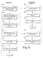
- Fig. 6 illustrates steps in a method in accordance with one embodiment.
- the method can be implemented in connection with any suitable hardware, software, firmware or combination thereof.
- aspects of the method can be implemented as computer-readable instructions that reside on one or more computer-readable media and which are executed to perform the described methodology.
- the illustrated method is separated into two sections-one of which is labeled "Application", the other of which is labeled "Downstream Component". This is done to illustrate which entities perform the acts about to be described. Accordingly, those acts that appear under the label "Application” are performed by the application, and those acts that appear under the label "Downstream Component" are performed by a component that resides downstream of the application.
- the downstream component can comprise driver software or a software representation of associated hardware that processes media data.
- the downstream component can comprise hardware componentry itself.
- Step 600 ascertains a public key associated with a component downstream from a playback application. Examples of how this can be done are provided above.
- Step 602 uses the public key to establish a secure channel between the playback application and the downstream component. Collectively, steps 600 and 602 establish trust between the playback application and the downstream component. One example of how this trust can be established is described in connection with Fig. 3 above. Other ways can, of course, be used without departing from the spirit and scope of the claimed subject matter.
- Step 604 uses the secure channel to send a command message to the downstream component.
- Any suitable command message structure can be utilized with but one example being given above in connection with Fig. 4.
- any suitable and/or appropriate types of commands can be sent from the application to the downstream component.
- commands that can be sent direct the downstream component to enable a particular type of content protection technology to protect media content or data that is to be processed by the system.
- Step 606 receives the command message via the secure channel. This step is performed by the downstream component to which the command message is sent. Step 608 then verifies the integrity of the command message. Any suitable method can be used to verify the integrity of the command message with but one example being given in connection with Fig. 4. Once the integrity of the command message is verified, step 610 implements an associated command contained in the command message.
- Step 612 uses the secure channel to send a status request to the downstream component.
- Any suitable type of status request structure can be utilized with but one example being given above in connection with Fig. 5.
- Step 614 receives the status request via the secure channel and step 616 responsively prepares a status message and sends the status message to the application using the secure channel.
- Any suitable status message structure can be utilized with but one example being given above in connection with Fig. 5.
- Step 618 receives the status message via the secure channel and step 620 verifies the integrity of the status message.
- Any suitable method can be used to verify the integrity of the status message, with but one example being given above.
- Fig. 7 illustrates a system, generally at 700, which can be utilized to implement the secure channel protocol described above.
- the inventive protocol is referred to as the Certified Output Protection Protocol or "COPP".
- COP Certified Output Protection Protocol
- Microsoft® DirectShow® which is an architecture for streaming media, is used as an example.
- Microsoft® DirectShow® provides for high quality playback of multimedia streams and supports a wide variety of formats including Advanced Streaming Format (ASF), Motion Picture Experts Group (MPEG), Audio-Video Interleaved (AVI), MPEG Audio Layer-3 (MP3), and WAV files.
- ASF Advanced Streaming Format
- MPEG Motion Picture Experts Group
- AVI Audio-Video Interleaved
- MP3 MPEG Audio Layer-3
- DirectShow® uses Microsoft® DirectDraw® and Microsoft® DirectSound® to render data efficiently to the system's sound and graphics cards.
- DirectDraw® is a display component of DirectX® that allows software designers to directly manipulate display memory, hardware blitters, hardware overlays, and flipping surfaces, as will be appreciated by the skilled artisan, DirectDraw® provides device-independent access to the device-specific display functionality in a direct 32-bit path. A 64-bit path also exists in the 64-bit versions of Windows®. DirectDraw® calls important functions in a driver that accesses the display card directly, without the intervention of the Windows® graphics device interface (GDI) or the device-independent bitmap (DIB) engine.
- GDI Windows® graphics device interface
- DIB device-independent bitmap
- DirectShow® synchronization is achieved by encapsulating the multimedia data in time-stamped media samples.
- DirectShow® uses a modular architecture in which operating system components called filters can be mixed and matched to provide support for many different scenarios.
- these filters can be assembled into a filter graph 704 that is utilized by a playback application 702 to cause multimedia data to be processed and rendered by a hardware device.
- filter graph 704 comprises a source filter 706 that reads media content and a decoder 708 (e.g. a WMV or MPEG-2 decoder) that decompresses the content.
- a video rendering component 710 receives the decompressed content or data and understands the hardware on which the content is to be rendered.
- a user mode DirectDraw® component 712 is provided and is a system-supplied dynamic-link library (DLL) that is loaded and called by DirectDraw® applications.
- DLL system-supplied dynamic-link library
- This component provides hardware emulation, manages the various DirectDraw® objects, and provides display memory and display management services, as will be appreciated by the skilled artisan.
- Kernel mode component 714 is the system-supplied graphics engine that is loaded by a kernel-mode display driver. This component performs parameter validation for the driver, thus making it easier to implement more robust drivers.
- a DirectDraw® graphics driver 716 is provided and is typically implemented by a third party hardware vendor.
- the protected content typically has some set of policies associated with it.
- the policies can establish the type and level of content protection that is to be used when the associated content is rendered. For example, if the content is going to be played out over a DVI connector, then a policy might establish that HDCP has to be enabled or the content will not be played.
- application 702 is aware of the policies that are associated with the content.
- the source filter 706 can include a component that is responsible for ascertaining the policy associated with the content and then notifying the application.
- API Application Program Interface
- system 700 first ascertains whether the policy can be enforced in this specific system.
- the way that this is accomplished, in this particular example, is through a user mode application program interface (API) called IAMCertifiedOutputProtection which is exposed by the video rendering component 710.
- API application program interface
- the IAMCertifiedOutputProtection interface consists of the following methods which can be called by the application:
- the AMCOPPCommand structure is the data structure that the application uses to send a command to a downstream component and would be used in an exchange such as the one illustrated in Fig. 4.
- the AMCOPPStatusInput structure is the data structure that the application uses to make a status request and would be used in an exchange such as the one illustrated on the left side of Fig. 5.
- the AMCOPPStatusOutput structure is the data structure that the graphics driver uses to provide status information back to the application and would be used in an exchange such as the one illustrated on the right side of Fig. 5.
- the DX-VA Certified Output Protection Protocol provides a means for passing commands from User mode applications, such as playback application 702, to a driver such as graphics driver 716, and for returning status from the driver to the user mode applications. As noted above, the channel through which the commands and status flow is protected.
- the Content Output Protection Protocol utilizes a DX-VA COPP device which is described in more detail below.
- DX-VA COPP device which is described in more detail below.
- a single component known as a DX-VA COPP device is created for each video session.
- two exemplary DX-VA COPP devices are shown within driver 716.
- the OX-VA COPP device represents an end point for COPP commands and status requests.
- a DX-VA COPP device can virtualize the protection settings of a physical connector. It is possible that a single physical connector can support multiple content protection types. For example, an S-Video connector may support Analog Content Protection and well as CGMS-A Line20 protection and CGMS-A Line21 protection.
- the COPP sample device driver code that appears later in this document shows one example of how a COPP device can be implemented by a driver.
- each DX-VA COPP device is configured to act appropriately when multiple video sessions are active on the computer.
- the driver 716 is asked to create multiple instances of the COPP DX-VA device as different processes try to configure the output display adapter settings via COPP.
- two instances of a DX-VA COPP devices have been created by driver 716.
- driver 716 For each physical connector that supports content protection, driver 716 should maintain a global reference count for each type and for each level. In the illustrated and described embodiment, driver 716 comprises a global state component that maintains this global state.
- the device When a COPP DX-VA device is created for a video session, the device should contain a local reference count for each protection type at each protection level. This is represented by the current protection level component inside each of the devices. A default level counter for the protection type should be set to the value 1, and all the other protection level counters for that type should be set to the value zero.
- the driver should inspect all the counters for that connector and ensure that the protection level is set to level that corresponds with highest level counter whose value is greater than zero.
- level B is the higher of the protection levels that can be applied to the physical connector.
- DX-VA COPP device 2 terminates, then the global state component will apply protection level A to the physical connector. Exemplary code samples below illustrate how this might be done.
- While the global reference counter is greater than zero, content protection should be applied to the output connector. As soon as the global reference counter reaches zero, content protection should be removed from the output connector. Whenever a driver receives a DestroyDevice call, the global reference counter should be decremented by the current level of the devices local reference counter. The connector protection should only be removed if the global reference counter for that connector reaches zero.
- DestroyDevice may be called while the device still has local reference counter greater than zero, one example of this would be if the user mode process terminated abnormally.
- video sessions are tied to a particular physical output connector.
- a video session, at the display driver level, is initialized by the following steps:
- the driver should decrement the global protection level count by the current local protection level count for the device being destroyed.
- the changed global protection level should be examined and the protection applied to the output connector should be adjusted accordingly.
- This function initializes the COPP DX-VA device that is being used for a particular video session.
- This function terminates the COPP DX-VA device that is being used for the video session.
- this function may be called while there is output protection still applied by the video session.
- the driver should undo the protection settings of this DX-VA COPP device and adjust the global protection settings accordingly.
- the driver should return the variable length digital certificate of the graphics hardware.
- the lpOutputData field of the DD_RENDERMOCOMPDATA structure points to a DXVA_COPPKeyExchangeOutput structure; the DXVA_COPPVariableLengthData field will have the required amount of space for the certificate as indicated in the previous COPPGetCertificateLength DXVA command.
- the driver will receive a concatenation of a 128-bit random data integrity session key, 32-bit random starting status sequence number, and 32-bit random starting command sequence number encrypted with the public key of the graphic hardware.
- the driver should return E_UNEXPECTED if it receives this function call before it receives the COPPKeyExchange function call or if it receives a subsequent COPPSequenceStart call.
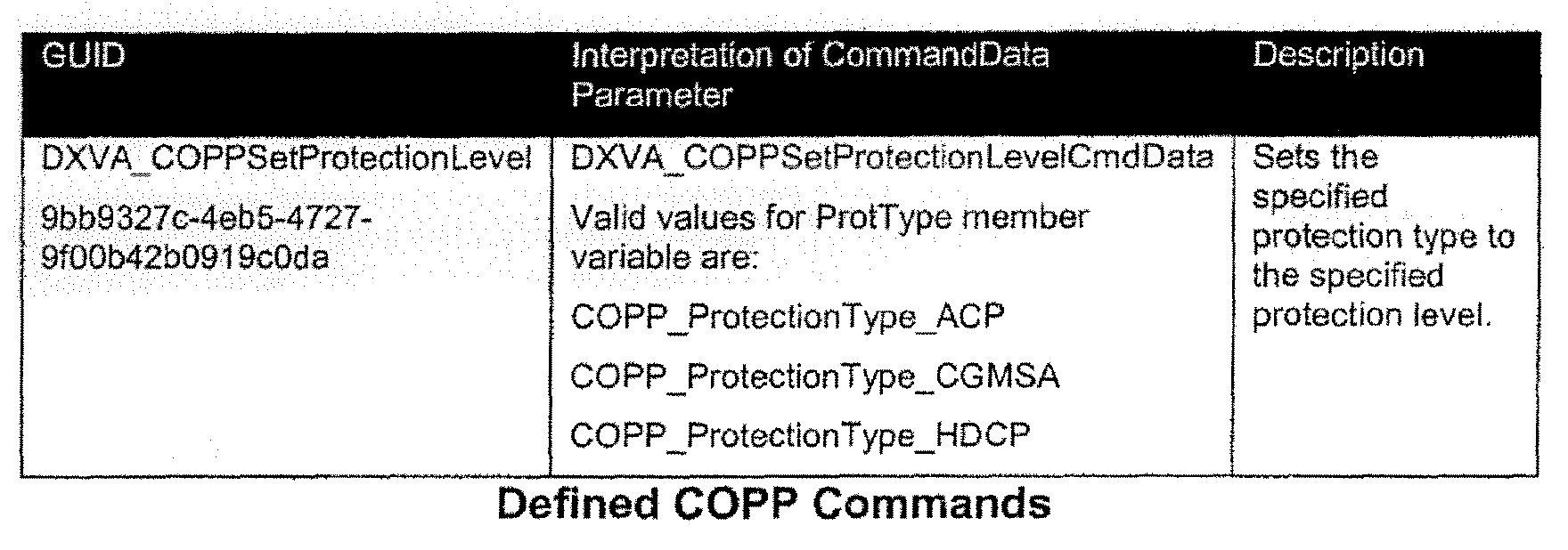
- a COPP command can comprise an instruction from the video session to change a protection level on the physical connector associated with the DX-VA COPP device.
- the driver should be able to support multiple video sessions all playing back content through the same physical connector, as noted above.
- the driver should return E_UNEXPECTED if it receives this function call before it receives the COPPKeyExchange or COPPSequenceStart function calls. Also, the driver should ensure that the parameters passed to it are valid for the given physical connector being used. The driver should return E_INVALIDARG if one or more of the parameters passed in the COPPCommand are not valid.
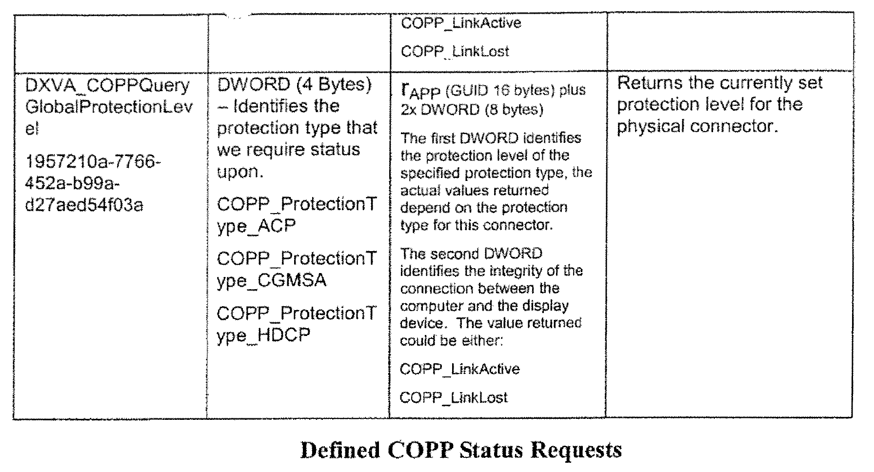
- a COPPQueryStatus is a request from the video session to retrieve information about the physical connector being used, the type of protection that can be applied to the content being transmitted through the physical connector, and the current protection level that is active on the physical connector.
- the driver should return E_UNEXPECTED if it receives this call before either COPPKeyExchange or COPPSequenceStart calls for this VideoSession.
- the table below lists a set of DX-VA status requests that a driver should expect to see in accordance with this embodiment.
- the DX-VA DDI is itself split into two functional groups: the "DX-VA container" and the "DX-VA device.”
- the purpose of the DX-VA container DDI group is to determine the number and capabilities of the various DX-VA devices contained by the display hardware. Therefore, in this implementation example, a DX-VA driver can only have a single container, but it can support multiple DX-VA devices.
- the sequence of steps to use the DDI from a user-mode component, such as the video rendering component 710 (Fig. 7) is as follows:
- This method maps directly to a CreateMoComp method of the DD_MOTIONCOMPCALLBACKS structure, where the GUID is the COPP Device GUID, pUncompData points to a structure that contains no data (all zeros), and pData points to NULL.
- the video rendering component will call the driver to create two DX-VA devices-one to perform the actual video decoding work as defined by the DirectX VA Video Decoding specification, and the other to be used strictly for applying protection to output connectors following the Content Output Protection Protocol.
- the sample code provide just below shows how a driver should map the CreateMoComp DDI call into calls to COPPOpenVideoSession .
- the sample code shows only how the CreateMoComp function is used for COPP. If a driver supports other DX-VA functions, such as decoding MPEG-2 video streams, the sample code below can be extended to include processing of additional DX-VA GUIDs.
- the driver should also implement the GetMoCompGuids method of the DD_MOTIONCOMPCALLBACKS structure.
- the following sample code shows one possible way of implementing this function in your driver.
- RenderMoComp will be called without calling BeginMoCompFrame or EndMoCompFrame .
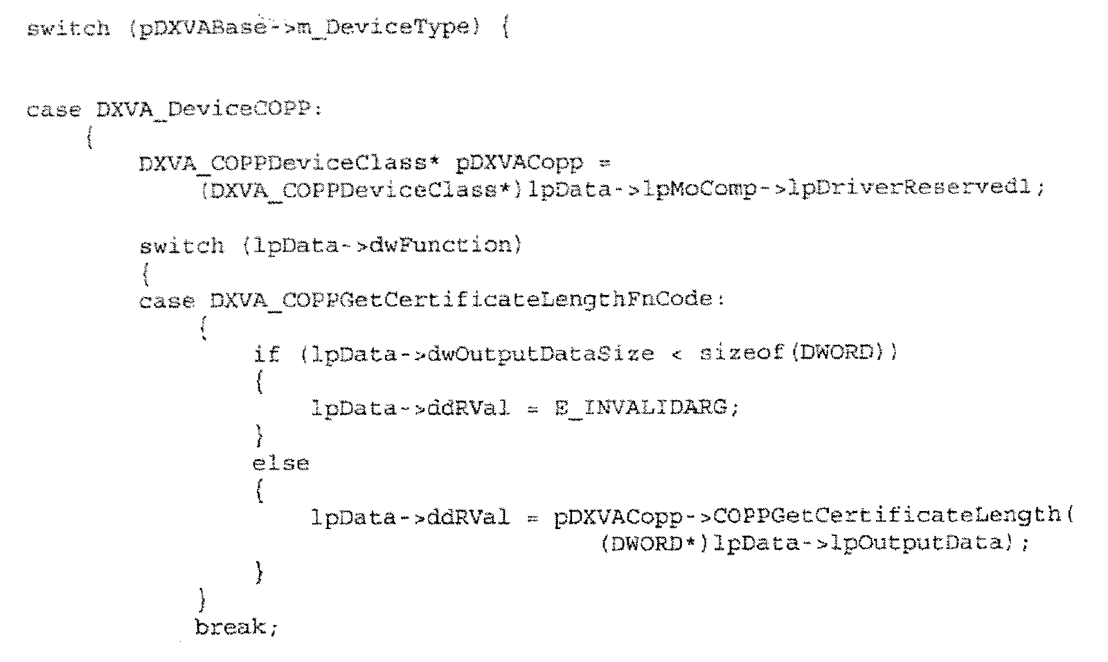
- the sample code below shows how a driver should map the RenderMoComp DDI call into calls to COPPGetCertificateLength .
- the sample code only shows how the RenderMoComp function is used for COPP control. If a driver supports other DX-VA functions, such as decoding MPEG-2 video streams, the sample code can be extended to include processing of additional DX-VA GUIDs.
- RenderMoComp will be called without calling BeginMoCompFrame or EndMoCompFrame .
- the sample code below shows how a driver should map the RenderMoComp DDI call into calls to COPPKeyExchange .
- the sample code only shows how the RenderMoComp function is used for COPP control. If a driver supports other DX-VA functions, such as decoding MPBG-2 video streams, the sample code can be extended to include processing of additional DX-VA GUIDs.
- RenderMoComp will be called without calling BeginMoCompFrame or EndMoCompFrame .
- the sample code below shows how a driver should map the RenderMoComp DDI call into calls to COPPSequenceStart .
- the sample code only shows how the RenderMoComp function is used for COPP control. If a driver supports other DX-VA functions, such as decoding MPEG-2 video streams, the sample code can be extended to include processing of additional DX-VA GUIDs.
- RenderMoComp will be called without calling BeginMoCompFrame or EndMoCompFrame.
- the sample code below shows how a driver should map the RenderMoComp DDI call into calls to COPPCommand .
- the sample code only shows how the RenderMoComp function is used for COPP control. If a driver supports other DX-VA functions, such as decoding MPEG-2 video streams, the sample code can be extended to include processing of additional DX-VA GUIDs.
- RenderMoComp will be called without calling BeginMoCompFrame or EndMoCompFrame .
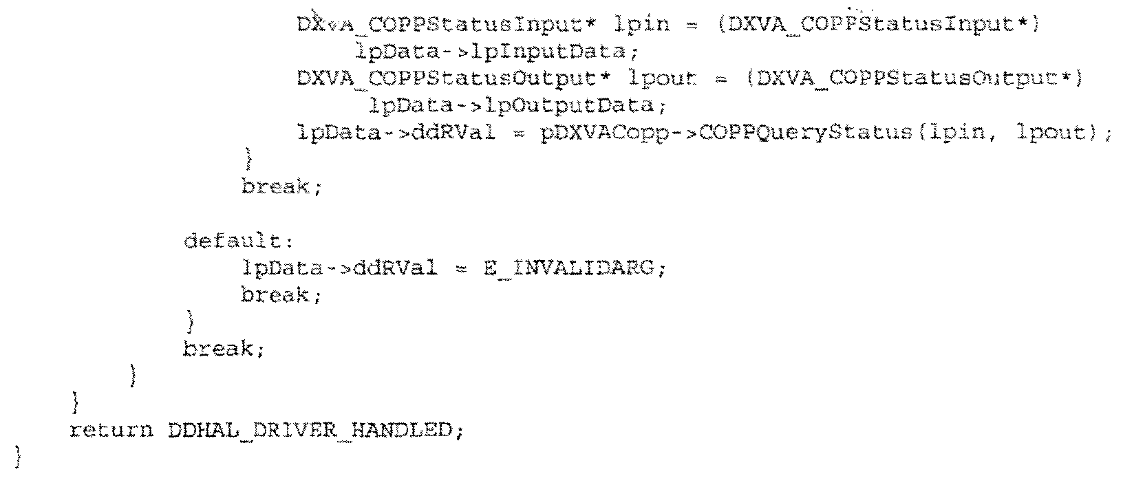
- the sample code below shows how your driver should map the RenderMoComp DDI call into calls to COPPQueryStatus .
- the sample code only shows how the RenderMoComp function is used for COPP control. If a driver supports other DX-VA functions, such as decoding MPEG-2 video streams, the sample code can be extended to include processing of additional DX-VA GUIDs.
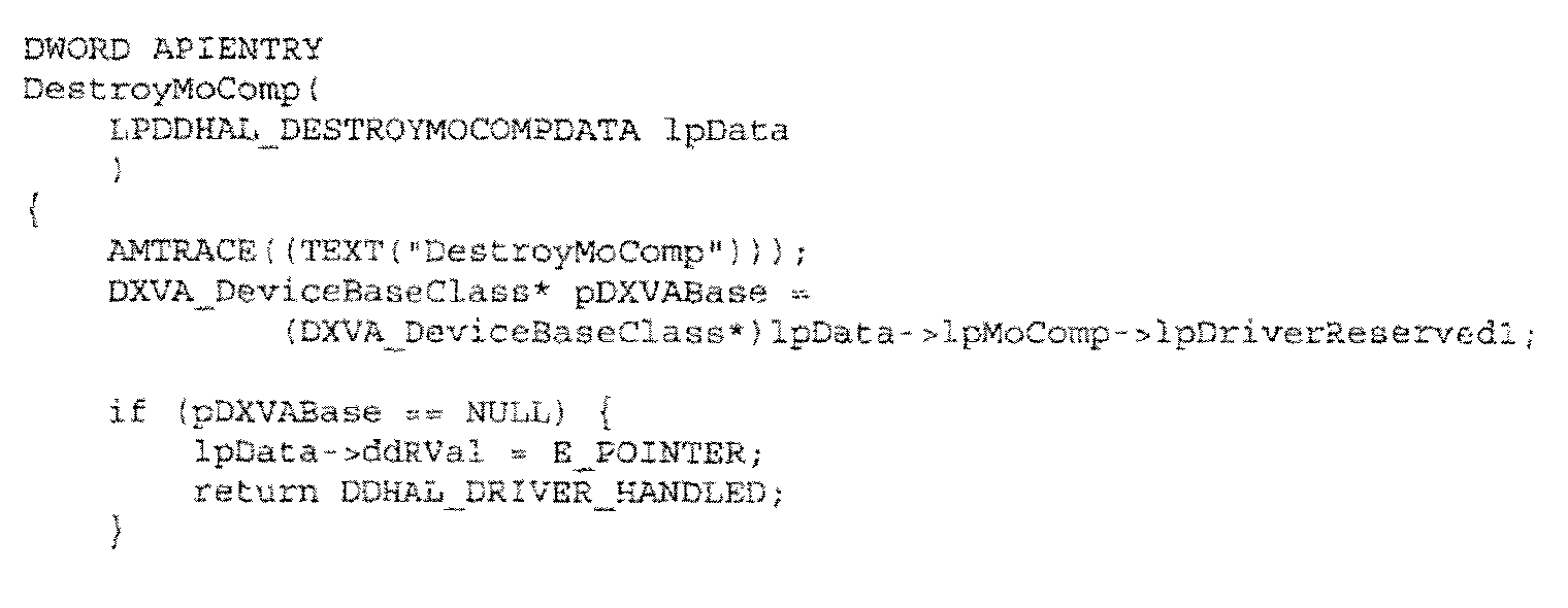
- This method maps directly to a DestroyMoComp method of the DD_MOTIONCOMPCALLBACKS structure.
- the following sample code shows how a driver should map the DestroyMoComp DDI call into calls to COPPCloseVideoSession .
- the sample code shows only how the DestroyMoComp function is used for the COPP device. If a driver supports other DX-VA functions, such as decoding MPEG-2 video streams, the sample code can be extended below to include processing of additional DX-VA GUIDs.
- Various embodiments described above enable media content protection by establishing a secure communication channel and, in some embodiments, a secure data channel, between a device such as a computer running a protected content playback application, and an associated driver, such as a graphics driver, of an associated display device such as a monitor, flat panel LCD, television and the like.
- Various embodiments address the needs of content providers and application vendors to signal that content protection should be applied to media output by utilizing an output adapter which physically links the computer and its display device as the gateway for the protected video path.
- the various embodiments provide a means for securely passing commands from a user mode playback application to a driver, such as a graphics driver, and securely returning status from the driver to the user mode application.
- a driver such as a graphics driver
- the described embodiments establish a secure communication channel and allow a user mode application to instruct an associated driver to enable content output protection on the physical connector between the computer and the display device.
Landscapes
- Engineering & Computer Science (AREA)
- Signal Processing (AREA)
- Multimedia (AREA)
- Theoretical Computer Science (AREA)
- Software Systems (AREA)
- Physics & Mathematics (AREA)
- Computer Security & Cryptography (AREA)
- General Physics & Mathematics (AREA)
- General Engineering & Computer Science (AREA)
- Computer Hardware Design (AREA)
- Health & Medical Sciences (AREA)
- Technology Law (AREA)
- General Health & Medical Sciences (AREA)
- Bioethics (AREA)
- Library & Information Science (AREA)
- Acoustics & Sound (AREA)
- Otolaryngology (AREA)
- Two-Way Televisions, Distribution Of Moving Picture Or The Like (AREA)
- Storage Device Security (AREA)
- Circuits Of Receivers In General (AREA)
Abstract
Description
| Value | Description |
| rGH | Random 32-bit random number generated by the graphics driver. |
| CertGH | Variable length digital certificate of graphics hardware. |
| PGH(rGH, kDI, status_start, command_start) | Concatenation of 32-bit random number from the graphics driver, 128-bit random data integrity session key, 32-bit random starting status sequence number and 32-bit random starting command sequence number encrypted with the public key of the graphic hardware. This value is 2048 bits long. |
Command, MACkDI (Command)
where the "Command" portion of the message includes not only an associated command from the application, but the associated command sequence number as well. The "MACkDI (Command)" portion of the message comprises a MAC of the "Command" portion that was computed by the application. When the
| Value | Description |
| Command | Variable length command data. |
| MACkDI (Command) | 128-bit MAC of the command data and command sequence number using the data integrity session key kDI. |
rAPP, Status Request
where rAPP is a random number generated by the application and "Status Request" is the actual request for status information. In response to receiving the status request from the application,
rAPP, Status, MACkDI(rAPP , Status)
where "Status" includes not only the status information, but the status sequence number as well. The MACkDI(rAPP , Status) portion of the message comprises a MAC of the random number provided by the application and the status information. When the application receives the status message, it can compute a MAC of the random number and the status information by running the MAC algorithm over the random number and the status information and then can compare this value with the value in the MACkDI(rAPP , Status) section of the message. By doing this, the application can confirm that the status message is genuine. The application can then use the contents of the message to verify that the status message is in the proper sequence (by virtue of the sequence number) and that the status information pertains to the status request that was previously sent by the application (by virtue of the random number rAPP).
| Value | Description |
| rAPP | 128-bit random number generated by the application. |
| Status | Variable length status data. |
| MACkDI (rAPP , Status) | 128-bit MAC of the status data, status sequence number and the random number provided by the application using the data integrity session key kDI. |


- Video Stream: A Video Stream is the principal image data that comprises a displayed video frame. Pixels from the Video Stream are always opaque and do not contain any per-pixel alpha data.
- Video Sub-stream: A Video Sub-stream is a channel of auxiliary image data that is required to be composited with a sample from the Video Stream prior to display of the combined Video frame. Examples of Video Sub-streams are NTSC Closed Caption images, DVD Sub-Picture images and PAL Teletext images. Another characteristic of Video Sub-streams is that they contain limited color range and per-pixel alpha information.
- Video Session: A video session consists of a Video Stream and possibly one or more Video Sub-streams which get combined with the video stream before it is displayed on an output device connected to the computer. There may be several Video Sessions active on the computer at any particular time, there may also be several Video Sessions active within a single process.
- DX-VA COPP Device: A new DX-VA device that supports receiving commands and status requests via the Content Output Protection Protocol.
- Connector: The physical output connection between the graphics hardware and a display device.
- Protection Type: The type of protection that can be applied to the signal being passed through a connector; more than one type of protection can be applied to a single connector.
- Protection Level: The level of protection that is applied to signal being passed through a connector. This value is dependent on the protection type - some protections types, for example HDCP, have only two protection levels, these being "on" and "off".
- GetMoCompGuids is called to determine if a driver supports a DX-VA COPP device for the output connector.
- Assuming the driver does support a DX-VA COPP device for the output connector CreateMoComp is called to create the DX-VA COPP device.
- RenderMoComp is the called with a DXVA_COPPGetCertificateLengthFnCode function code to determine the length of the variable length graphics hardware certificate that should be used for this session.
- RenderMoComp is called with a DXVA_COPPKeyExchangeFnCode function code to pass the Video Sessions Application certificate to the driver. The driver returns a 128 bit privacy key and a copy of its variable length graphics hardware certificate.
- Finally, RenderMoComp is called with a DXVA_COPPSequenceStartFnCode function code to indicate that the Video Session has started with a 32 bit Command Sequence start code and 32 bit Status Sequence start code.
- Display Mode changes;
- Attaching or detaching a monitor from the Windows® desktop;
- Entering a full screen DOS box;
- Starting any DDraw or D3D exclusive mode application;
- Fast User Switching;
- Adding or removing monitors from the Windows® desktop;
- Locking the workstation or pressing Alt-Ctrl-Del on Windows® XP professional edition;
- Attaching to the workstation via "Remote Desktop Connection";
- Entering a power saving mode, for example "Suspend" or "Hibernate"; and
- Unexpected application termination, for example a "page fault".










- dwNumBuffers is zero.
- lpBufferInfo is NULL.
- dwFunction is defined as DXVA_COPPGetCertificateLengthFnCode.
- lpInputData is NULL.
- lpOutputData will point to a single DWORD.

- dwNumBuffers is zero.
- lpBufferInfo is NULL.
- dwFunction is defined as DXVA_COPPKeyExchangeFnCode.
- lpInputData is NULL.
- IpOutputData will point to a DXVA_COPPKeyExchangeOutput data structure.

- dwNumBuffers is zero.
- lpBufferInfo is NULL.
- dwFunction is defined as DXVA_COPPSequenceStartFnCode.
- IpInputData will point to a DXVA_COPPSignature data structure.
- lpOutputData is NULL.

- dwNumBuffers is zero.
- IpBufferInfo is NULL.
- dwFunction is defined as DXVA_COPPCommandFnCode.
- lplnputData will point to a DXVA_COPPCommand data structure.
- lpOutputData is NULL.

- dwNumBuffers is zero.
- lpBufferInfo is NULL.
- dwFunction is defined as DXVA_COPPQueryStatusFnCode.
- lpInputData will point to a DXVA_COPPStatusInput data structure.
- lpOutputData will point to a DXVA_COPPStatusOutput data structure.


Claims (46)
- A method comprising:establishing a secure communication channel between a media playback application and a component downstream from the media playback application; andusing the secure communication channel to at least enable the media playback application to instruct the downstream component to enable one or more of a number of different types of content protection technologies to protect media content that is provided over a physical connector.
- The method of claim 1 further comprising using the secure communication channel to enable the media playback application to instruct the downstream component as to how to apply one or more of the different types of content protection technologies.
- The method of claim 1, wherein the downstream component comprises a software component.
- The method of claim 1 further comprising using the secure communication channel to enable the media playback application to request status information from the downstream component.
- The method of claim 1 further comprising:using the secure communication channel to enable the media playback application to request status information from the downstream component; andusing the secure communication channel to receive status information from the downstream component.
- The method of claim 1 further comprising:using the secure communication channel to enable the media playback application to request status information from the downstream component; andusing the secure communication channel to receive status information from the downstream component, wherein the status information pertains to instructions that were previously sent by the media playback application.
- The method of claim 1 further comprising:using the secure communication channel to enable the media playback application to request status information from the downstream component; andusing the secure communication channel to receive status information from the downstream component, wherein the status information does not pertain to instructions that were previously sent by the media playback application.
- One or more computer-readable media having computer-readable instructions which, when executed, implement the method of claim 1.
- A computing system embodying the one or more computer-readable media of claim 8.
- A system comprising:one or more computer-readable media;a software component resident on the media and configured to:establish a secure communication channel with a media playback application;use the secure communication channel to receive instructions from the media playback application to enable one or more of a number of different types of content protection technologies to protect media content that is provided over a physical connector; andfor at least some of the content protection technologies, receive instructions to configure the content protection technologies.
- The system of claim 10, wherein the software component comprises a software driver.
- The system of claim 10, wherein the software component is further configured to use the secure communication channel to receive status requests from the media playback application.
- The system of claim 10, wherein the software component is further configured to use the secure communication channel to receive status requests from the media playback application, and wherein the software component is further configured to use the secure communication channel to send status information to the media playback application.
- The system of claim 10, wherein the software component is further configured to use the secure communication channel to receive status requests from the media playback application, and wherein the software component is further configured to use the secure communication channel to send status information to the media playback application, wherein the status information pertains to instructions that were previously received from the media playback application.
- The system of claim 10, wherein the software component is further configured to use the secure communication channel to receive status requests from the media playback application, and wherein the software component is further configured to use the secure communication channel to send status information to the media playback application, wherein the status information does not pertain to instructions that were previously received from the media playback application.
- A computing system embodying the system of claim 10.
- A method comprising:establishing trust between a media playback application and a downstream component;establishing a secure channel between the media playback application and the downstream component using a public key associated with the downstream component to encrypt:a random number provided by the downstream component;a data integrity key; andone or more starting numbers;sending the encrypted data to the downstream component;using the secure channel to send a command message to the downstream component, the command message comprising a data section that contains a command, and an authentication section that contains data that can be used to authenticate the command;using the secure channel to request status information from the downstream component; andusing the secure channel to receive a status message from the downstream component, the status message comprising a data section that contains status information, and an authentication section that contains data that can be used to authenticate the status information.
- The method of claim 17, wherein said one or more starting numbers comprise a starting status sequence number and a starting command sequence number, said numbers being useable to ascertain, respectively, whether a status message or a command message has been lost.
- The method of claim 17, wherein the act of using the secure channel to request status information from the downstream component comprises sending, with the request, a random number, and wherein the authentication section of the status message comprises data associated with the random number.
- The method of claim 17, wherein the authentication sections of the command message and the status message comprise data that has been processed using the data integrity key.
- The method of claim 17, wherein the command message contains a command instructing the downstream component to enable one or more of a number of different types of content protection technologies to protect media content that is provided over a physical connector.
- The method of claim 17, wherein the downstream component comprises a software driver.
- One or more computer-readable media having computer-readable instructions which, when executed, implement the method of claim 17.
- A computing system embodying the one or more computer-readable media of claim 23.
- The method of claim 17 further comprising using the secure channel to provide protected media content to the downstream component.
- A system comprising:one or more computer-readable media;a software component resident on the media and configured to:establish trust with a media playback application;establish a secure channel with the media playback application by providing a public key associated with the software component to the media playback application and receiving back, from the media playback application, encrypted data that has been encrypted with the public key, the encrypted data comprising:a random number previously provided by the software component;a data integrity key; andone or more starting numbers;use the secure channel to receive a command message from the media playback application, the command message comprising a data section that contains a command, and an authentication section that contains data that can be used to authenticate the command;use the secure channel to receive status requests from the media playback application; anduse the secure channel to send a status message to the media playback application, the status message comprising a data section that contains status information, and an authentication section that contains data that can be used to authenticate the status information.
- The system of claim 26, wherein said one or more starting numbers comprise a starting status sequence number and a starting command sequence number, said numbers being useable to ascertain, respectively, whether a status message or a command message has been lost.
- The system of claim 26, wherein the authentication sections of the command message and the status message comprise data that has been processed using the data integrity key.
- The system of claim 26, wherein the command message contains a command instructing the software component to enable one or more of a number of different types of content protection technologies to protect media content that is provided over a physical connector.
- The system of claim 26, wherein the command message contains a command instructing the software component to enable one or more of a number of different types of content protection technologies to protect media content that is provided over a physical connector, and wherein the software component is configured to enable a plurality of different types of content protection technologies.
- A computing system embodying the system of claim 26.
- An application program interface (API) embodied on a computer-readable media, the API comprising:a first method that is callable by a media playback application for establishing trust between the media playback application and a software driver component;a second method callable by the media playback application for setting up a session key between the media playback application and the software driver component;a third method that is callable by the media playback application to instruct the software driver component to enable one or more of a number of different types of content protection technologies to protect media content that is provided over a physical connector; anda fourth method that is callable by the media playback application to request status information from the software driver component.
- The API of claim 32, wherein the first method receives back a random number generated by the software driver and a digital certificate.
- The API of claim 32, wherein the second method provides an encrypted concatenation of a random number provided by graphics hardware, one or more session keys, a starting status sequence number, a starting command sequence number.
- The API of claim 32, wherein the API is exposed by a video rendering component.
- A method comprising:calling a device driver to create an instance of a content protection device, individual content protection devices being associated with individual video sessions and serving as an endpoint for communication with a playback application that can send commands and status requests to the content protection devices;maintaining, with the device driver, a global reference count for each type and level of content protection that is applied to protect content;maintaining, with at least one content protection device, a local reference count for each type and level of content protection applied through the content protection device; andadjusting the global and local reference counts in accordance with changing content protection types or levels.
- A software architecture comprising:wherein individual content protection devices support callable methods comprising:one or more computer-readable media;software driver code embodied on the computer-readable media and configured to implement multiple content protection devices that are associated with individual video sessions and which serve as an endpoint for communication with a playback application that can send commands and status requests to the content protection devices, wherein the software driver code comprises:a first method that can be called to determine if a driver supports content protection devices for a given output connector;a second method that can be called to create an associated content protection device; anda third method that can be called to determine a length associated with a graphics hardware certificate and to start a video session;a first method to query a graphics hardware certificate length;a second method to return a variable length graphics hardware digital certificate;a third method for receiving a concatenation of a data integrity session key, a starting status sequence number and a starting command sequence number all of which are encrypted with a public key associated with the graphics hardware;a fourth method for receiving a command to change content protection on a physical connector associated with the content protection device; anda fifth method for querying information about the physical connector being used, the type of protection that can be applied to content being transmitted through the physical connector, and the current protection level that is active on the physical connector.
- The architecture of claim 37, wherein the content protection device's first method maps directly to the software driver code's third method.
- The architecture of claim 37, wherein the content protection device's second method maps directly to the software driver code's third method.
- The architecture of claim 37, wherein the content protection device's third method maps directly to the software driver cade's third method.
- The architecture of claim 37, wherein the content protection device's fourth method maps directly to the software driver code's third method.
- The architecture of claim 37, wherein the content protection device's fifth method maps directly to the software driver code's third method.
- A system comprising:means for establishing a secure communication channel between a media playback application and a component downstream from the media playback application; andmeans for using the secure communication channel to at least enable the media playback application to instruct the downstream component to enable one or more of a number of different types of content protection technologies to protect media content that is provided over a physical connector.
- The system of claim 43, wherein said downstream component comprises a software component.
- The system of claim 43, wherein said downstream component comprises a hardware component.
- The system of claim 43, wherein said downstream component comprises a graphics hardware component.
Applications Claiming Priority (2)
| Application Number | Priority Date | Filing Date | Title |
|---|---|---|---|
| US798688 | 1997-02-12 | ||
| US10/798,688 US7703141B2 (en) | 2004-03-11 | 2004-03-11 | Methods and systems for protecting media content |
Publications (3)
| Publication Number | Publication Date |
|---|---|
| EP1582962A2 true EP1582962A2 (en) | 2005-10-05 |
| EP1582962A3 EP1582962A3 (en) | 2006-05-17 |
| EP1582962B1 EP1582962B1 (en) | 2019-08-07 |
Family
ID=34887641
Family Applications (1)
| Application Number | Title | Priority Date | Filing Date |
|---|---|---|---|
| EP05101873.7A Expired - Lifetime EP1582962B1 (en) | 2004-03-11 | 2005-03-10 | System and method for protecting media content |
Country Status (5)
| Country | Link |
|---|---|
| US (2) | US7703141B2 (en) |
| EP (1) | EP1582962B1 (en) |
| JP (1) | JP4809616B2 (en) |
| KR (1) | KR101099311B1 (en) |
| CN (2) | CN1677920B (en) |
Cited By (1)
| Publication number | Priority date | Publication date | Assignee | Title |
|---|---|---|---|---|
| CN108124731A (en) * | 2017-12-22 | 2018-06-08 | 兰溪市沉默生物科技有限公司 | A kind of preparation method of potting environment-friendly substrate |
Families Citing this family (40)
| Publication number | Priority date | Publication date | Assignee | Title |
|---|---|---|---|---|
| US7370212B2 (en) | 2003-02-25 | 2008-05-06 | Microsoft Corporation | Issuing a publisher use license off-line in a digital rights management (DRM) system |
| US20060242406A1 (en) * | 2005-04-22 | 2006-10-26 | Microsoft Corporation | Protected computing environment |
| US8074287B2 (en) * | 2004-04-30 | 2011-12-06 | Microsoft Corporation | Renewable and individualizable elements of a protected environment |
| KR101049129B1 (en) * | 2004-07-30 | 2011-07-15 | 엘지전자 주식회사 | Cable broadcast receiver and its status information processing method |
| KR101092438B1 (en) * | 2004-08-05 | 2011-12-13 | 엘지전자 주식회사 | Cable broadcast receiver and its diagnostic method |
| US8347078B2 (en) | 2004-10-18 | 2013-01-01 | Microsoft Corporation | Device certificate individualization |
| US8336085B2 (en) | 2004-11-15 | 2012-12-18 | Microsoft Corporation | Tuning product policy using observed evidence of customer behavior |
| US8438645B2 (en) | 2005-04-27 | 2013-05-07 | Microsoft Corporation | Secure clock with grace periods |
| US8725646B2 (en) | 2005-04-15 | 2014-05-13 | Microsoft Corporation | Output protection levels |
| US9363481B2 (en) * | 2005-04-22 | 2016-06-07 | Microsoft Technology Licensing, Llc | Protected media pipeline |
| US9436804B2 (en) | 2005-04-22 | 2016-09-06 | Microsoft Technology Licensing, Llc | Establishing a unique session key using a hardware functionality scan |
| US20060265758A1 (en) | 2005-05-20 | 2006-11-23 | Microsoft Corporation | Extensible media rights |
| US8139768B2 (en) * | 2006-01-19 | 2012-03-20 | Microsoft Corporation | Encrypting content in a tuner device and analyzing content protection policy |
| US8302200B2 (en) * | 2007-04-27 | 2012-10-30 | Tl Digital Systems L.L.C. | Protected intra-system interconnect for digital rights management in electrical computers and digital data processing systems |
| US7934083B2 (en) * | 2007-09-14 | 2011-04-26 | Kevin Norman Taylor | Configurable access kernel |
| US8059820B2 (en) * | 2007-10-11 | 2011-11-15 | Microsoft Corporation | Multi-factor content protection |
| US20100262961A1 (en) * | 2007-10-30 | 2010-10-14 | Lg Electronics Inc. | Method and system for downloading software |
| JP5266330B2 (en) * | 2007-11-01 | 2013-08-21 | エルジー エレクトロニクス インコーポレイティド | Data processing method and IPTV receiving device |
| US8046586B1 (en) * | 2007-12-14 | 2011-10-25 | Nvidia Corporation | Method and system for determining the compliance of encrypted and non-encrypted display outputs |
| US8291501B2 (en) * | 2008-02-08 | 2012-10-16 | Cheng Holdings, Llc | Validation of protected intra-system interconnects for digital rights management in electrical computers and digital data processing systems |
| US8837737B2 (en) * | 2008-09-16 | 2014-09-16 | Telefonaktiebolaget Lm Ericsson (Publ) | Key management in a communication network |
| JP2011188111A (en) * | 2010-03-05 | 2011-09-22 | Sony Corp | Communication terminal device, network device, communication system, and communication method |
| US9767840B2 (en) * | 2011-08-18 | 2017-09-19 | Apple Inc. | Securing protected content during video playback |
| CN102522100A (en) * | 2011-11-29 | 2012-06-27 | 邹中奇 | Video learning system and processing method |
| US8874926B1 (en) * | 2012-03-08 | 2014-10-28 | Sandia Corporation | Increasing security in inter-chip communication |
| US9094733B2 (en) * | 2012-03-31 | 2015-07-28 | Intel Corporation | Methods and systems for cryptographic access control of video |
| US9848218B2 (en) | 2013-01-28 | 2017-12-19 | Samsung Electronics Co., Ltd. | Source device, content providing method using the source device, sink device and controlling method of the sink device |
| US9740886B2 (en) * | 2013-03-15 | 2017-08-22 | Sony Interactive Entertainment Inc. | Enhanced security for hardware decoder accelerator |
| US10142108B2 (en) * | 2013-06-17 | 2018-11-27 | Qube Cinema, Inc. | Copy protection scheme for digital audio and video content authenticated HDCP receivers |
| US20150355818A1 (en) | 2014-06-04 | 2015-12-10 | Sonos, Inc. | Continuous Playback Queue |
| US9654536B2 (en) * | 2014-06-04 | 2017-05-16 | Sonos, Inc. | Cloud queue playback policy |
| CN104092690B (en) * | 2014-07-15 | 2017-03-01 | 金亚科技股份有限公司 | Streaming Media review Media Stream bandwidth control system and method |
| US9430619B2 (en) * | 2014-09-10 | 2016-08-30 | Microsoft Technology Licensing, Llc | Media decoding control with hardware-protected digital rights management |
| WO2016049219A1 (en) * | 2014-09-25 | 2016-03-31 | Good Technology Corporation | Retrieving media content |
| US10103872B2 (en) * | 2014-09-26 | 2018-10-16 | Intel Corporation | Securing audio communications |
| US9742780B2 (en) * | 2015-02-06 | 2017-08-22 | Microsoft Technology Licensing, Llc | Audio based discovery and connection to a service controller |
| FR3046000B1 (en) * | 2015-12-21 | 2018-02-16 | Oberthur Technologies | METHOD FOR RECEIVING DATA WITHIN AN ELECTRONIC ENTITY AND ELECTRONIC ENTITY THEREFOR |
| US10819526B2 (en) * | 2018-02-19 | 2020-10-27 | Microsoft Technology Licensing, Llc | Identity-based certificate authority system architecture |
| KR101996333B1 (en) * | 2018-04-04 | 2019-07-04 | 이니텍(주) | Method of Key Agreement and Authentication for Communicating with IoT Device and Method for Tranceiving Message Using the Same |
| US12067135B2 (en) * | 2020-12-14 | 2024-08-20 | Netflix, Inc. | Secure video capture platform |
Family Cites Families (12)
| Publication number | Priority date | Publication date | Assignee | Title |
|---|---|---|---|---|
| US5812930A (en) * | 1996-07-10 | 1998-09-22 | International Business Machines Corp. | Information handling systems with broadband and narrowband communication channels between repository and display systems |
| US5825879A (en) * | 1996-09-30 | 1998-10-20 | Intel Corporation | System and method for copy-protecting distributed video content |
| JP2001075870A (en) * | 1999-09-02 | 2001-03-23 | Sony Corp | Information signal transmission method, information signal transmission system, information signal transmission device, and information signal reception device |
| CN1277364C (en) * | 1999-12-02 | 2006-09-27 | 三洋电机株式会社 | Data recording device, data supply device and data transmission system |
| US7353209B1 (en) | 2000-01-14 | 2008-04-01 | Microsoft Corporation | Releasing decrypted digital content to an authenticated path |
| US20020057795A1 (en) * | 2000-11-10 | 2002-05-16 | Spurgat Jeffrey Jonathan | Content protection through the audio and video decrypting and decoding device |
| US7499545B1 (en) * | 2001-02-05 | 2009-03-03 | Ati Technologies, Inc. | Method and system for dual link communications encryption |
| US7131004B1 (en) * | 2001-08-31 | 2006-10-31 | Silicon Image, Inc. | Method and apparatus for encrypting data transmitted over a serial link |
| US7203310B2 (en) * | 2001-12-04 | 2007-04-10 | Microsoft Corporation | Methods and systems for cryptographically protecting secure content |
| US7296154B2 (en) * | 2002-06-24 | 2007-11-13 | Microsoft Corporation | Secure media path methods, systems, and architectures |
| US7233666B2 (en) * | 2003-05-29 | 2007-06-19 | Intel Corporation | Method and apparatus for increasing the entropy of a pseudorandom number |
| US7584353B2 (en) * | 2003-09-12 | 2009-09-01 | Trimble Navigation Limited | Preventing unauthorized distribution of media content within a global network |
-
2004
- 2004-03-11 US US10/798,688 patent/US7703141B2/en active Active
-
2005
- 2005-03-10 JP JP2005067120A patent/JP4809616B2/en not_active Expired - Fee Related
- 2005-03-10 EP EP05101873.7A patent/EP1582962B1/en not_active Expired - Lifetime
- 2005-03-11 KR KR1020050020623A patent/KR101099311B1/en not_active Expired - Fee Related
- 2005-03-11 CN CN2005100563286A patent/CN1677920B/en not_active Expired - Fee Related
- 2005-03-11 CN CN2010101924526A patent/CN101859358B/en not_active Expired - Fee Related
-
2010
- 2010-03-02 US US12/715,529 patent/US8397069B2/en not_active Expired - Fee Related
Cited By (1)
| Publication number | Priority date | Publication date | Assignee | Title |
|---|---|---|---|---|
| CN108124731A (en) * | 2017-12-22 | 2018-06-08 | 兰溪市沉默生物科技有限公司 | A kind of preparation method of potting environment-friendly substrate |
Also Published As
| Publication number | Publication date |
|---|---|
| EP1582962A3 (en) | 2006-05-17 |
| JP4809616B2 (en) | 2011-11-09 |
| US20100161985A1 (en) | 2010-06-24 |
| KR101099311B1 (en) | 2011-12-26 |
| EP1582962B1 (en) | 2019-08-07 |
| JP2005304000A (en) | 2005-10-27 |
| US8397069B2 (en) | 2013-03-12 |
| CN101859358A (en) | 2010-10-13 |
| KR20060044315A (en) | 2006-05-16 |
| US20050204163A1 (en) | 2005-09-15 |
| CN1677920B (en) | 2011-01-19 |
| US7703141B2 (en) | 2010-04-20 |
| CN101859358B (en) | 2013-08-21 |
| CN1677920A (en) | 2005-10-05 |
Similar Documents
| Publication | Publication Date | Title |
|---|---|---|
| US8397069B2 (en) | Methods and systems for protecting media content | |
| JP4807925B2 (en) | Graphic system component authentication method and system | |
| JP4522645B2 (en) | Method and system for cryptographically protecting secure content | |
| US7634090B2 (en) | Packet based high definition high-bandwidth digital content protection | |
| CN100397896C (en) | Source device and method of controlling output to sink device according to each content | |
| US7752674B2 (en) | Secure media path methods, systems, and architectures | |
| JP2005051558A (en) | Transmission device, reception device, and transmission / reception system | |
| US8473750B2 (en) | Chipset security offload engine | |
| US7920701B1 (en) | System and method for digital content protection | |
| EP1801725A2 (en) | Chipset security offload engine |
Legal Events
| Date | Code | Title | Description |
|---|---|---|---|
| PUAI | Public reference made under article 153(3) epc to a published international application that has entered the european phase |
Free format text: ORIGINAL CODE: 0009012 |
|
| AK | Designated contracting states |
Kind code of ref document: A2 Designated state(s): AT BE BG CH CY CZ DE DK EE ES FI FR GB GR HU IE IS IT LI LT LU MC NL PL PT RO SE SI SK TR |
|
| AX | Request for extension of the european patent |
Extension state: AL BA HR LV MK YU |
|
| RTI1 | Title (correction) |
Free format text: SYSTEM AND METHOD FOR PROTECTING MEDIA CONTENT |
|
| PUAL | Search report despatched |
Free format text: ORIGINAL CODE: 0009013 |
|
| AK | Designated contracting states |
Kind code of ref document: A3 Designated state(s): AT BE BG CH CY CZ DE DK EE ES FI FR GB GR HU IE IS IT LI LT LU MC NL PL PT RO SE SI SK TR |
|
| AX | Request for extension of the european patent |
Extension state: AL BA HR LV MK YU |
|
| 17P | Request for examination filed |
Effective date: 20061019 |
|
| 17Q | First examination report despatched |
Effective date: 20061219 |
|
| AKX | Designation fees paid |
Designated state(s): AT BE BG CH CY CZ DE DK EE ES FI FR GB GR HU IE IS IT LI LT LU MC NL PL PT RO SE SI SK TR |
|
| RAP1 | Party data changed (applicant data changed or rights of an application transferred) |
Owner name: MICROSOFT TECHNOLOGY LICENSING, LLC |
|
| STAA | Information on the status of an ep patent application or granted ep patent |
Free format text: STATUS: EXAMINATION IS IN PROGRESS |
|
| REG | Reference to a national code |
Ref country code: DE Ref legal event code: R079 Ref document number: 602005056107 Country of ref document: DE Free format text: PREVIOUS MAIN CLASS: G06F0001000000 Ipc: G06F0021100000 |
|
| RIC1 | Information provided on ipc code assigned before grant |
Ipc: H04N 21/835 20110101ALI20181219BHEP Ipc: G06F 21/60 20130101ALI20181219BHEP Ipc: H04N 21/4367 20110101ALI20181219BHEP Ipc: H04N 21/443 20110101ALI20181219BHEP Ipc: H04N 21/41 20110101ALI20181219BHEP Ipc: G06F 21/10 20130101AFI20181219BHEP Ipc: H04N 21/4405 20110101ALI20181219BHEP |
|
| GRAP | Despatch of communication of intention to grant a patent |
Free format text: ORIGINAL CODE: EPIDOSNIGR1 |
|
| STAA | Information on the status of an ep patent application or granted ep patent |
Free format text: STATUS: GRANT OF PATENT IS INTENDED |
|
| INTG | Intention to grant announced |
Effective date: 20190301 |
|
| GRAS | Grant fee paid |
Free format text: ORIGINAL CODE: EPIDOSNIGR3 |
|
| GRAA | (expected) grant |
Free format text: ORIGINAL CODE: 0009210 |
|
| STAA | Information on the status of an ep patent application or granted ep patent |
Free format text: STATUS: THE PATENT HAS BEEN GRANTED |
|
| AK | Designated contracting states |
Kind code of ref document: B1 Designated state(s): AT BE BG CH CY CZ DE DK EE ES FI FR GB GR HU IE IS IT LI LT LU MC NL PL PT RO SE SI SK TR |
|
| REG | Reference to a national code |
Ref country code: GB Ref legal event code: FG4D |
|
| REG | Reference to a national code |
Ref country code: CH Ref legal event code: EP Ref country code: AT Ref legal event code: REF Ref document number: 1164948 Country of ref document: AT Kind code of ref document: T Effective date: 20190815 |
|
| REG | Reference to a national code |
Ref country code: DE Ref legal event code: R096 Ref document number: 602005056107 Country of ref document: DE |
|
| REG | Reference to a national code |
Ref country code: IE Ref legal event code: FG4D |
|
| REG | Reference to a national code |
Ref country code: NL Ref legal event code: FP |
|
| REG | Reference to a national code |
Ref country code: LT Ref legal event code: MG4D |
|
| PG25 | Lapsed in a contracting state [announced via postgrant information from national office to epo] |
Ref country code: SE Free format text: LAPSE BECAUSE OF FAILURE TO SUBMIT A TRANSLATION OF THE DESCRIPTION OR TO PAY THE FEE WITHIN THE PRESCRIBED TIME-LIMIT Effective date: 20190807 Ref country code: FI Free format text: LAPSE BECAUSE OF FAILURE TO SUBMIT A TRANSLATION OF THE DESCRIPTION OR TO PAY THE FEE WITHIN THE PRESCRIBED TIME-LIMIT Effective date: 20190807 Ref country code: PT Free format text: LAPSE BECAUSE OF FAILURE TO SUBMIT A TRANSLATION OF THE DESCRIPTION OR TO PAY THE FEE WITHIN THE PRESCRIBED TIME-LIMIT Effective date: 20191209 Ref country code: BG Free format text: LAPSE BECAUSE OF FAILURE TO SUBMIT A TRANSLATION OF THE DESCRIPTION OR TO PAY THE FEE WITHIN THE PRESCRIBED TIME-LIMIT Effective date: 20191107 Ref country code: LT Free format text: LAPSE BECAUSE OF FAILURE TO SUBMIT A TRANSLATION OF THE DESCRIPTION OR TO PAY THE FEE WITHIN THE PRESCRIBED TIME-LIMIT Effective date: 20190807 |
|
| REG | Reference to a national code |
Ref country code: AT Ref legal event code: MK05 Ref document number: 1164948 Country of ref document: AT Kind code of ref document: T Effective date: 20190807 |
|
| PG25 | Lapsed in a contracting state [announced via postgrant information from national office to epo] |
Ref country code: ES Free format text: LAPSE BECAUSE OF FAILURE TO SUBMIT A TRANSLATION OF THE DESCRIPTION OR TO PAY THE FEE WITHIN THE PRESCRIBED TIME-LIMIT Effective date: 20190807 Ref country code: GR Free format text: LAPSE BECAUSE OF FAILURE TO SUBMIT A TRANSLATION OF THE DESCRIPTION OR TO PAY THE FEE WITHIN THE PRESCRIBED TIME-LIMIT Effective date: 20191108 Ref country code: IS Free format text: LAPSE BECAUSE OF FAILURE TO SUBMIT A TRANSLATION OF THE DESCRIPTION OR TO PAY THE FEE WITHIN THE PRESCRIBED TIME-LIMIT Effective date: 20191207 |
|
| PG25 | Lapsed in a contracting state [announced via postgrant information from national office to epo] |
Ref country code: TR Free format text: LAPSE BECAUSE OF FAILURE TO SUBMIT A TRANSLATION OF THE DESCRIPTION OR TO PAY THE FEE WITHIN THE PRESCRIBED TIME-LIMIT Effective date: 20190807 |
|
| PG25 | Lapsed in a contracting state [announced via postgrant information from national office to epo] |
Ref country code: AT Free format text: LAPSE BECAUSE OF FAILURE TO SUBMIT A TRANSLATION OF THE DESCRIPTION OR TO PAY THE FEE WITHIN THE PRESCRIBED TIME-LIMIT Effective date: 20190807 Ref country code: EE Free format text: LAPSE BECAUSE OF FAILURE TO SUBMIT A TRANSLATION OF THE DESCRIPTION OR TO PAY THE FEE WITHIN THE PRESCRIBED TIME-LIMIT Effective date: 20190807 Ref country code: PL Free format text: LAPSE BECAUSE OF FAILURE TO SUBMIT A TRANSLATION OF THE DESCRIPTION OR TO PAY THE FEE WITHIN THE PRESCRIBED TIME-LIMIT Effective date: 20190807 Ref country code: RO Free format text: LAPSE BECAUSE OF FAILURE TO SUBMIT A TRANSLATION OF THE DESCRIPTION OR TO PAY THE FEE WITHIN THE PRESCRIBED TIME-LIMIT Effective date: 20190807 Ref country code: IT Free format text: LAPSE BECAUSE OF FAILURE TO SUBMIT A TRANSLATION OF THE DESCRIPTION OR TO PAY THE FEE WITHIN THE PRESCRIBED TIME-LIMIT Effective date: 20190807 Ref country code: DK Free format text: LAPSE BECAUSE OF FAILURE TO SUBMIT A TRANSLATION OF THE DESCRIPTION OR TO PAY THE FEE WITHIN THE PRESCRIBED TIME-LIMIT Effective date: 20190807 |
|
| PGFP | Annual fee paid to national office [announced via postgrant information from national office to epo] |
Ref country code: GB Payment date: 20200226 Year of fee payment: 16 Ref country code: DE Payment date: 20200225 Year of fee payment: 16 |
|
| PG25 | Lapsed in a contracting state [announced via postgrant information from national office to epo] |
Ref country code: CZ Free format text: LAPSE BECAUSE OF FAILURE TO SUBMIT A TRANSLATION OF THE DESCRIPTION OR TO PAY THE FEE WITHIN THE PRESCRIBED TIME-LIMIT Effective date: 20190807 Ref country code: IS Free format text: LAPSE BECAUSE OF FAILURE TO SUBMIT A TRANSLATION OF THE DESCRIPTION OR TO PAY THE FEE WITHIN THE PRESCRIBED TIME-LIMIT Effective date: 20200224 Ref country code: SK Free format text: LAPSE BECAUSE OF FAILURE TO SUBMIT A TRANSLATION OF THE DESCRIPTION OR TO PAY THE FEE WITHIN THE PRESCRIBED TIME-LIMIT Effective date: 20190807 |
|
| REG | Reference to a national code |
Ref country code: DE Ref legal event code: R097 Ref document number: 602005056107 Country of ref document: DE |
|
| PGFP | Annual fee paid to national office [announced via postgrant information from national office to epo] |
Ref country code: FR Payment date: 20200214 Year of fee payment: 16 |
|
| PLBE | No opposition filed within time limit |
Free format text: ORIGINAL CODE: 0009261 |
|
| STAA | Information on the status of an ep patent application or granted ep patent |
Free format text: STATUS: NO OPPOSITION FILED WITHIN TIME LIMIT |
|
| PG2D | Information on lapse in contracting state deleted |
Ref country code: IS |
|
| 26N | No opposition filed |
Effective date: 20200603 |
|
| PG25 | Lapsed in a contracting state [announced via postgrant information from national office to epo] |
Ref country code: SI Free format text: LAPSE BECAUSE OF FAILURE TO SUBMIT A TRANSLATION OF THE DESCRIPTION OR TO PAY THE FEE WITHIN THE PRESCRIBED TIME-LIMIT Effective date: 20190807 |
|
| PG25 | Lapsed in a contracting state [announced via postgrant information from national office to epo] |
Ref country code: MC Free format text: LAPSE BECAUSE OF FAILURE TO SUBMIT A TRANSLATION OF THE DESCRIPTION OR TO PAY THE FEE WITHIN THE PRESCRIBED TIME-LIMIT Effective date: 20190807 |
|
| REG | Reference to a national code |
Ref country code: CH Ref legal event code: PL |
|
| REG | Reference to a national code |
Ref country code: BE Ref legal event code: MM Effective date: 20200331 |
|
| PG25 | Lapsed in a contracting state [announced via postgrant information from national office to epo] |
Ref country code: LU Free format text: LAPSE BECAUSE OF NON-PAYMENT OF DUE FEES Effective date: 20200310 |
|
| PG25 | Lapsed in a contracting state [announced via postgrant information from national office to epo] |
Ref country code: CH Free format text: LAPSE BECAUSE OF NON-PAYMENT OF DUE FEES Effective date: 20200331 Ref country code: IE Free format text: LAPSE BECAUSE OF NON-PAYMENT OF DUE FEES Effective date: 20200310 Ref country code: LI Free format text: LAPSE BECAUSE OF NON-PAYMENT OF DUE FEES Effective date: 20200331 |
|
| PG25 | Lapsed in a contracting state [announced via postgrant information from national office to epo] |
Ref country code: BE Free format text: LAPSE BECAUSE OF NON-PAYMENT OF DUE FEES Effective date: 20200331 |
|
| REG | Reference to a national code |
Ref country code: DE Ref legal event code: R119 Ref document number: 602005056107 Country of ref document: DE |
|
| GBPC | Gb: european patent ceased through non-payment of renewal fee |
Effective date: 20210310 |
|
| PG25 | Lapsed in a contracting state [announced via postgrant information from national office to epo] |
Ref country code: DE Free format text: LAPSE BECAUSE OF NON-PAYMENT OF DUE FEES Effective date: 20211001 Ref country code: GB Free format text: LAPSE BECAUSE OF NON-PAYMENT OF DUE FEES Effective date: 20210310 Ref country code: FR Free format text: LAPSE BECAUSE OF NON-PAYMENT OF DUE FEES Effective date: 20210331 |
|
| PG25 | Lapsed in a contracting state [announced via postgrant information from national office to epo] |
Ref country code: CY Free format text: LAPSE BECAUSE OF FAILURE TO SUBMIT A TRANSLATION OF THE DESCRIPTION OR TO PAY THE FEE WITHIN THE PRESCRIBED TIME-LIMIT Effective date: 20190807 |
|
| PGFP | Annual fee paid to national office [announced via postgrant information from national office to epo] |
Ref country code: NL Payment date: 20220215 Year of fee payment: 18 |
|
| P01 | Opt-out of the competence of the unified patent court (upc) registered |
Effective date: 20230505 |
|
| REG | Reference to a national code |
Ref country code: NL Ref legal event code: MM Effective date: 20230401 |
|
| PG25 | Lapsed in a contracting state [announced via postgrant information from national office to epo] |
Ref country code: NL Free format text: LAPSE BECAUSE OF NON-PAYMENT OF DUE FEES Effective date: 20230401 |