EP1582837A1 - Enveloppe de fragmentation pour charge explosive - Google Patents
Enveloppe de fragmentation pour charge explosive Download PDFInfo
- Publication number
- EP1582837A1 EP1582837A1 EP05290558A EP05290558A EP1582837A1 EP 1582837 A1 EP1582837 A1 EP 1582837A1 EP 05290558 A EP05290558 A EP 05290558A EP 05290558 A EP05290558 A EP 05290558A EP 1582837 A1 EP1582837 A1 EP 1582837A1
- Authority
- EP
- European Patent Office
- Prior art keywords
- envelope
- fragmentation
- intermediate zone
- network
- profile
- Prior art date
- Legal status (The legal status is an assumption and is not a legal conclusion. Google has not performed a legal analysis and makes no representation as to the accuracy of the status listed.)
- Granted
Links
- 238000013467 fragmentation Methods 0.000 title claims abstract description 29
- 238000006062 fragmentation reaction Methods 0.000 title claims abstract description 29
- 239000002360 explosive Substances 0.000 title claims abstract description 15
- 230000003313 weakening effect Effects 0.000 claims description 13
- 239000011324 bead Substances 0.000 claims description 8
- 230000007423 decrease Effects 0.000 claims description 4
- 238000005474 detonation Methods 0.000 description 6
- 239000003999 initiator Substances 0.000 description 6
- 230000000977 initiatory effect Effects 0.000 description 5
- 238000003754 machining Methods 0.000 description 4
- 230000000694 effects Effects 0.000 description 3
- 239000012634 fragment Substances 0.000 description 3
- 239000000463 material Substances 0.000 description 3
- 208000012868 Overgrowth Diseases 0.000 description 1
- 230000000881 depressing effect Effects 0.000 description 1
- 230000009977 dual effect Effects 0.000 description 1
- 238000004093 laser heating Methods 0.000 description 1
- 238000000034 method Methods 0.000 description 1
- 230000037452 priming Effects 0.000 description 1
- 230000002787 reinforcement Effects 0.000 description 1
Images


Classifications
-
- F—MECHANICAL ENGINEERING; LIGHTING; HEATING; WEAPONS; BLASTING
- F42—AMMUNITION; BLASTING
- F42B—EXPLOSIVE CHARGES, e.g. FOR BLASTING, FIREWORKS, AMMUNITION
- F42B12/00—Projectiles, missiles or mines characterised by the warhead, the intended effect, or the material
- F42B12/02—Projectiles, missiles or mines characterised by the warhead, the intended effect, or the material characterised by the warhead or the intended effect
- F42B12/20—Projectiles, missiles or mines characterised by the warhead, the intended effect, or the material characterised by the warhead or the intended effect of high-explosive type
- F42B12/22—Projectiles, missiles or mines characterised by the warhead, the intended effect, or the material characterised by the warhead or the intended effect of high-explosive type with fragmentation-hull construction
- F42B12/24—Projectiles, missiles or mines characterised by the warhead, the intended effect, or the material characterised by the warhead or the intended effect of high-explosive type with fragmentation-hull construction with grooves, recesses or other wall weakenings
Definitions
- the technical field of the invention is that of fragmentation envelopes for explosive charge.
- Fragmentation envelopes are usually metallic cylindrical parts with or without a network fragilization.
- envelopes are intended to receive a load explosive and they cause splinters when loading is initiated.
- the combination of the detonation waves can indeed lead to a Mach wave effect that causes at the level of desired projection plan over-fragmentation of the material of the envelope. Splinters generated in this area have too small dimensions. This results in a loss of perforating efficiency for the load compared to an initiation at one end only.
- the subject of the invention is an envelope of fragmentation for an explosive charge intended to be initiated at both ends, envelope comprising a profile externally generally cylindrical and characterized in that it includes means to modify the fragmentation characteristics of an intermediate zone compared to those of the end zones.
- the means allowing to modify the characteristics of fragmentation include an internal profile of the envelope that is such that the thickness of the envelope at an intermediate zone is greater than it is at each end of the envelope.
- the intermediate zone at the level of which the thickness of the envelope is maximum may be disposed substantially equidistant from each end of the envelope.
- the internal profile may be such that the thickness increases steadily between each end and the area intermediate.
- the internal profile may thus be a toric surface.
- the internal profile may include a bead disposed at the intermediate zone and which will be located between two substantially cylindrical surfaces extending from the bead at each end of the envelope.
- the envelope may also include a network of lines of weakness on the external profile and / or internal.
- This network can be formed by a set of lines helicals extending from one end to the other of the envelope.
- Each helical line may have a variable pitch which will grow between each end of the envelope and the area intermediary so as to create a network whose meshes located in the intermediate zone will have a size which will be greater than that of the meshes located at the level of two ends.
- the weakening lines can be realized under the form of furrows.
- the furrows may have a greater depth in the vicinity of the intermediate zone
- the envelope can have a constant thickness and the means to modify the fragmentation characteristics can then have a network of weakening lines on the external and / or internal profile, network formed by a set of helical lines extending from one end to the other of the envelope, each helical line having a variable pitch which decreases between each end of the envelope and the area intermediary so as to create a network whose meshes located at the intermediate zone are of a size that is smaller than the meshes at the level of the two ends.
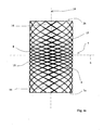
- Figures 1a, 1b and 1c show an envelope 1 of fragmentation for an explosive charge.
- the envelope 1 is here represented alone. She presents a external profile the cylindrical and its internal profile 1b delimits an internal volume 9 intended to receive a load explosive.
- Dotted lines have two lids end 3a and 3b each carrying an initiator 4a, 4b.
- the initiators are connected to a non-boot device represent.
- the envelope loaded and bearing the initiators constitutes an explosive charge generating splinters. initiation simultaneous operation of the two initiators 4a and 4b will lead to progression in the explosive charge of two fronts detonation waves 5a and 5b converging towards one another.
- Such a dual priming charge leads to a projection of shards that are directed in a way preferential following a radial plane 6 intersecting the envelope 1 at an intermediate zone 7 arranged to equal distance of the two ends 2a and 2b of the envelope 1.
- these means are constituted by a particular machining of the internal profile 1 1b, machining such that the thickness of the envelope 1 is growing between each end 2a or 2b of the envelope 1 and the intermediate zone 7.
- the thickness of the envelope 1 is thus maximum at level of intermediate zone 7 and minimum at the level of ends 2a and 2b.
- the profile internal is such that the thickness of the envelope 1 increases by regular way between each end 2a, 2b and the zone intermediate 7.
- This internal profile is constituted here by a toric surface portion of axis 10.
- the rate of variation of thickness along the envelope will be determined by the skilled person according to the mechanical characteristics of the material of the envelope 1 as well as detonation features of the explosive used.
- This reinforcement of the envelope 1 at the level of the zone intermediate 7 makes it possible to improve its mechanical resistance to level of an area where the Mach effect engendered by the combination of detonation waves 5a and 5b from each detonator 4a, 4b is maximum.
- a network of weakening lines 8 This network can be realized on the external profile la and / or internal 1b.
- the lines can be made by any method of known embrittlement: mechanical or laser machining, electronic bombardment, laser heating ...
- the network is formed in a conventional way by a set of helical lines 8 having as axis the axis 10 of the envelope 1 and which extend from one end 2a to the other end 2b of the envelope 1. These lines are here grooves machined along the helical lines.
- the lines 8 delimit meshes 11, 12 corresponding to the desired size for the chips that will be generated by the envelope 1.
- each helical line 8 a a variable step. This step is steadily increasing between end 2a (or 2b) of the envelope 1 and the zone intermediate 7, then it decreases between the intermediate zone 7 and the other end 2b (or 2a).
- weakening lines 8 are closer to the each other in the vicinity of the ends 2a and 2b that they are not at intermediate zone 7.
- the splinters produced by the envelope 1 at the level of median zone 7 are therefore larger in size than chips generated near the ends 2a and 2b.
- Such an arrangement allows, despite the presence of wave of Mach, to better control the dimensions of splinters generated.
- a line of helical embrittlement is usually performed using a tool animated by a translational motion while the envelope is animated of a rotation movement.
- a machine to numerical control it is therefore sufficient to use a machine to numerical control in which it will be possible to program (as a function of time) the feed speed in translation of the tool or the speed of rotation of the envelope.
- Figures 2a, 2b and 2c show a second mode of embodiment of the invention.
- This mode differs from the previous one by the geometry of the profile internal 1b.
- the thickness of the envelope 1 is maximum intermediate zone level 7.
- the internal profile 1b here comprises a bead 13 which is disposed at the intermediate zone 7. This bead is located between two substantially cylindrical surfaces 14a and 14b extending from the bead to each end 2a, 2b of the envelope 1.
- the total length of the bead depends on the nature of the explosive used.
- This embodiment makes it possible to control more specifies the focus of the splinters at the zone level intermediate 7.
- FIGS. 2a, 2b and 2c show one such network, which, as in the previous example, consists of machined helical lines 8 extending from one end 2a at the other end 2b of the envelope 1.
- Each helical line 8 has a variable pitch which is steadily growing between each end 2a or 2b of the envelope 1 and the intermediate zone 7.
- the meshes 11 of the weakening network which are located at the intermediate zone 7 therefore have a size which is greater than that of meshes 12 located at level of the two ends 2a, 2b.
- the skilled person will choose the shape of the internal profile 1b, the number of lines of weakness and the variation of steps, depending on the size of the fragments desired, mechanical characteristics of the material of the envelope 1 as well as detonation features of the explosive set implemented.
- Figure 3 shows such a variant in which the furrows 8 are thus deeper at the zone level intermediate 7.
- a given groove 8 extending in a manner continues from one end 2a to the other end 2b of envelope 1, it will suffice to realize this variant of vary the machining depth during the turning. This variation will be achieved continuously by depressing the grooving tool more and more up to the area intermediate 7 and then withdrawing it gradually after this intermediate zone.
- This variant will be implemented when there is a delay between the initiation of each end detonator. Indeed in this case the Mach wave reaches its maximum closer to the detonator initiated last. The thickness must be more important in this area where the Mach wave is the stronger.
- Figures 4a, 4b and 4c show a third mode of embodiment of the invention.
- profile internal 1b of the envelope is cylindrical.
- the means for change the fragmentation features include a network of particular weakening lines.
- This network is formed of helical lines 8 machined which extend from one end 2a to the other end 2b of the envelope 1.
- Each helical line 8 still has a variable pitch, but this not decreases here between one end 2a (or 2b) of the envelope and the intermediate zone 7 then he believes between the intermediate zone 7 and the other end 2b (or 2a).
- the mesh configuration here is the opposite of that described above with reference to Figures 1c and 2c. This choice is due to the fact that the envelope here has a thickness constant. The effects of Mach are maximal at the level of intermediate zone 7 and, the thickness of the envelope being not reinforced, it is then necessary to control the fragmentation characteristics at this area of play on the size of the mesh separating the lines of fragilization 8.
- the network of weakening lines 8 may well heard to be realized on the external profile or on the profile internal and the depth of the lines may also be variable, the maximum depth being provided at the level of the intermediate zone 7.
Landscapes
- Engineering & Computer Science (AREA)
- Chemical & Material Sciences (AREA)
- Combustion & Propulsion (AREA)
- General Engineering & Computer Science (AREA)
- Earth Drilling (AREA)
- Drilling And Exploitation, And Mining Machines And Methods (AREA)
- Crushing And Pulverization Processes (AREA)
Abstract
Description
- la figure 1a est une vue en coupe longitudinale d'une enveloppe de charge selon un premier mode de réalisation de l'invention,
- la figure 1b est une vue d'une extrémité de l'enveloppe de charge selon la figure 1a,
- la figure 1c est une vue de la surface externe de ce premier mode de réalisation de l'enveloppe de charge,
- la figure 2a est une vue en coupe longitudinale d'une enveloppe de charge selon un deuxième mode de réalisation de l'invention,
- la figure 2b est une vue d'une extrémité de l'enveloppe de charge selon la figure 2a,
- la figure 2c est une vue de la surface externe de ce deuxième mode de réalisation de l'enveloppe de charge.
- la figure 3 est une vue partielle d'une variante de réalisation de l'invention,
- la figure 4a est une vue en coupe longitudinale d'une enveloppe de charge selon un troisième mode de réalisation de l'invention,
- la figure 4b est une vue d'une extrémité de l'enveloppe de charge selon la figure 4a,
- la figure 4c est une vue de la surface externe de ce troisième mode de réalisation de l'enveloppe de charge.
Claims (12)
- Enveloppe de fragmentation (1) pour une charge explosive destinée à être amorcée à ses deux extrémités (2a,2b), enveloppe comprenant un profil externe (1a) globalement cylindrique et caractérisée en ce qu'elle comprend des moyens permettant de modifier les caractéristiques de fragmentation d'une zone intermédiaire (7) par rapport à celles des zones d'extrémité (2a,2b).
- Enveloppe de fragmentation selon la revendication 1, caractérisée en ce que les moyens permettant de modifier les caractéristiques de fragmentation comprennent un profil interne (1b) de l'enveloppe (1) qui est tel que l'épaisseur de l'enveloppe au niveau d'une zone intermédiaire (7) est supérieure à ce qu'elle est au niveau de chaque extrémité (2a,2b) de l'enveloppe.
- Enveloppe de fragmentation selon la revendication 2, caractérisée en ce que la zone intermédiaire (7) au niveau de laquelle l'épaisseur de l'enveloppe (1) est maximale est disposée sensiblement à égale distance de chaque extrémité (2a,2b) de l'enveloppe.
- Enveloppe de fragmentation selon la revendication 3, caractérisée en ce que le profil interne (1b) est tel que l'épaisseur croit de façon régulière entre chaque extrémité (2a,2b) et la zone intermédiaire (7).
- Enveloppe de fragmentation selon la revendication 4, caractérisée en ce que le profil interne (1b) est une surface torique.
- Enveloppe de fragmentation selon la revendication 3, caractérisée en ce que le profil interne (1b) comprend un bourrelet (13) disposé au niveau de la zone intermédiaire (7) et qui est situé entre deux surfaces sensiblement cylindriques (14a,14b) s'étendant du bourrelet (13) à chaque extrémité (2a,2b) de l'enveloppe.
- Enveloppe de fragmentation selon une des revendications 2 à 6, caractérisée en ce qu'elle comporte un réseau de lignes de fragilisation (8) réalisé sur le profil externe (1a) et/ou interne (1b).
- Enveloppe de fragmentation selon la revendication 7, caractérisée en ce que le réseau est formé par un ensemble de lignes hélicoïdales (8) s'étendant d'une extrémité (2a) à l'autre (2b) de l'enveloppe (1).
- Enveloppe de fragmentation selon la revendication 8, caractérisée en ce que chaque ligne hélicoïdale (8) a un pas variable qui croit entre chaque extrémité (2a,2b) de l'enveloppe et la zone intermédiaire (7) de façon à réaliser un réseau dont les mailles (11) situées au niveau de la zone intermédiaire (7) ont une taille qui est supérieure à celle des mailles (12) situées au niveau des deux extrémités (2a,2b).
- Enveloppe de fragmentation selon une des revendications 7 à 9, caractérisée en ce que les lignes de fragilisation (8) sont réalisées sous la forme de sillons.
- Enveloppe de fragmentation selon la revendication 10, caractérisée en ce que les sillons ont une profondeur plus importante au voisinage de la zone intermédiaire (7).
- Enveloppe de fragmentation selon la revendication 1, caractérisée en ce que l'enveloppe (1) a une épaisseur constante et en ce que les moyens permettant de modifier les caractéristiques de fragmentation comportent un réseau (8) de lignes de fragilisation réalisé sur le profil externe (1a) et/ou interne (1b), réseau formé par un ensemble de lignes hélicoïdales (8) s'étendant d'une extrémité (2a) à l'autre (2b) de l'enveloppe, chaque ligne hélicoïdale ayant un pas variable qui décroít entre chaque extrémité (2a,2b) de l'enveloppe et la zone intermédiaire (7) de façon à réaliser un réseau dont les mailles (15) situées au niveau de la zone intermédiaire (7) ont une taille qui est inférieure à celle des mailles (16) situées au niveau des deux extrémités (2a, 2b) .
Applications Claiming Priority (2)
| Application Number | Priority Date | Filing Date | Title |
|---|---|---|---|
| FR0403408A FR2868523B1 (fr) | 2004-03-30 | 2004-03-30 | Enveloppe de fragmentation pour charge explosive |
| FR0403408 | 2004-03-30 |
Publications (2)
| Publication Number | Publication Date |
|---|---|
| EP1582837A1 true EP1582837A1 (fr) | 2005-10-05 |
| EP1582837B1 EP1582837B1 (fr) | 2014-01-01 |
Family
ID=34878479
Family Applications (1)
| Application Number | Title | Priority Date | Filing Date |
|---|---|---|---|
| EP20050290558 Expired - Lifetime EP1582837B1 (fr) | 2004-03-30 | 2005-03-14 | Enveloppe de fragmentation pour charge explosive |
Country Status (3)
| Country | Link |
|---|---|
| EP (1) | EP1582837B1 (fr) |
| ES (1) | ES2447017T3 (fr) |
| FR (1) | FR2868523B1 (fr) |
Cited By (7)
| Publication number | Priority date | Publication date | Assignee | Title |
|---|---|---|---|---|
| WO2008145259A1 (fr) * | 2007-05-30 | 2008-12-04 | Rheinmetall Waffe Munition Gmbh | Ogive |
| DE102008060737A1 (de) * | 2008-12-05 | 2010-06-10 | TDW Gesellschaft für verteidigungstechnische Wirksysteme mbH | Verfahren und Vorrichtung zur Erzeugung unterschiedlicher Splittergrößen |
| FR2961590A1 (fr) * | 2010-06-16 | 2011-12-23 | Nexter Munitions | Obus comportant une enveloppe fragmentable. |
| WO2012097790A1 (fr) * | 2010-12-15 | 2012-07-26 | Krauss-Maffei Wegmann Gmbh & Co. Kg | Enveloppe de projectile pour un projectile explosif et procédé de traitement d'une enveloppe de projectile |
| EP2963377A3 (fr) * | 2014-06-30 | 2016-04-13 | Marc Hartmann | Appareil de libération de fluide dans l'atmosphère |
| US9329009B1 (en) | 2013-03-15 | 2016-05-03 | Vista Outdoor Operations Llc | Manufacturing process to produce programmed terminal performance projectiles |
| CN112556512A (zh) * | 2020-11-12 | 2021-03-26 | 中国兵器装备研究院 | 预控破片的制造方法及预控破片 |
Families Citing this family (1)
| Publication number | Priority date | Publication date | Assignee | Title |
|---|---|---|---|---|
| PL423968A1 (pl) * | 2017-12-20 | 2019-07-01 | Wojskowy Instytut Techniczny Uzbrojenia | 122 mm niekierowany pocisk rakietowy |
Citations (3)
| Publication number | Priority date | Publication date | Assignee | Title |
|---|---|---|---|---|
| US5040464A (en) * | 1977-05-31 | 1991-08-20 | The United States Of America As Represented By The Secretary Of The Navy | Controlled fragmentation with fragment mix |
| US5157225A (en) * | 1983-04-19 | 1992-10-20 | The United States Of America As Represented By The Secretary Of The Navy | Controlled fragmentation warhead |
| FR2685077A1 (fr) | 1991-12-13 | 1993-06-18 | Thomson Brandt Armements | Dispositif explosif a fragmentation programmable. |
-
2004
- 2004-03-30 FR FR0403408A patent/FR2868523B1/fr not_active Expired - Fee Related
-
2005
- 2005-03-14 ES ES05290558T patent/ES2447017T3/es not_active Expired - Lifetime
- 2005-03-14 EP EP20050290558 patent/EP1582837B1/fr not_active Expired - Lifetime
Patent Citations (3)
| Publication number | Priority date | Publication date | Assignee | Title |
|---|---|---|---|---|
| US5040464A (en) * | 1977-05-31 | 1991-08-20 | The United States Of America As Represented By The Secretary Of The Navy | Controlled fragmentation with fragment mix |
| US5157225A (en) * | 1983-04-19 | 1992-10-20 | The United States Of America As Represented By The Secretary Of The Navy | Controlled fragmentation warhead |
| FR2685077A1 (fr) | 1991-12-13 | 1993-06-18 | Thomson Brandt Armements | Dispositif explosif a fragmentation programmable. |
Cited By (11)
| Publication number | Priority date | Publication date | Assignee | Title |
|---|---|---|---|---|
| WO2008145259A1 (fr) * | 2007-05-30 | 2008-12-04 | Rheinmetall Waffe Munition Gmbh | Ogive |
| AU2008255286B2 (en) * | 2007-05-30 | 2012-07-05 | Rheinmetall Waffe Munition Gmbh | Warhead |
| US8528480B2 (en) | 2007-05-30 | 2013-09-10 | Rheinmetall Waffe Munition Gmbh | Warhead |
| DE102008060737A1 (de) * | 2008-12-05 | 2010-06-10 | TDW Gesellschaft für verteidigungstechnische Wirksysteme mbH | Verfahren und Vorrichtung zur Erzeugung unterschiedlicher Splittergrößen |
| FR2961590A1 (fr) * | 2010-06-16 | 2011-12-23 | Nexter Munitions | Obus comportant une enveloppe fragmentable. |
| WO2012097790A1 (fr) * | 2010-12-15 | 2012-07-26 | Krauss-Maffei Wegmann Gmbh & Co. Kg | Enveloppe de projectile pour un projectile explosif et procédé de traitement d'une enveloppe de projectile |
| US9568291B2 (en) | 2010-12-15 | 2017-02-14 | Krauss-Maffei Wegmann Gmbh & Co. Kg | Projectile casing for an explosive projectile and method for handling a projectile casing |
| US9329009B1 (en) | 2013-03-15 | 2016-05-03 | Vista Outdoor Operations Llc | Manufacturing process to produce programmed terminal performance projectiles |
| US9360284B1 (en) | 2013-03-15 | 2016-06-07 | Vista Outdoor Operations Llc | Manufacturing process to produce metalurgically programmed terminal performance projectiles |
| EP2963377A3 (fr) * | 2014-06-30 | 2016-04-13 | Marc Hartmann | Appareil de libération de fluide dans l'atmosphère |
| CN112556512A (zh) * | 2020-11-12 | 2021-03-26 | 中国兵器装备研究院 | 预控破片的制造方法及预控破片 |
Also Published As
| Publication number | Publication date |
|---|---|
| ES2447017T3 (es) | 2014-03-11 |
| FR2868523A1 (fr) | 2005-10-07 |
| FR2868523B1 (fr) | 2008-06-27 |
| EP1582837B1 (fr) | 2014-01-01 |
Similar Documents
| Publication | Publication Date | Title |
|---|---|---|
| EP0279732B1 (fr) | Projectile perforant à noyau dur et guide ductile et son procédé de fabrication | |
| BE1010801A3 (fr) | Outil de forage et/ou de carottage. | |
| EP0099307B1 (fr) | Procédé et dispositif de formage local en expansion de précision pour tubes métalliques de grande longueur | |
| EP0059142A1 (fr) | Chargement propulsif birégime à canal en trompette comportant une section en étoile | |
| CA2439977C (fr) | Element filete pour joint filete tubulaire resistant a la fatigue | |
| EP1582837A1 (fr) | Enveloppe de fragmentation pour charge explosive | |
| FR2771167A1 (fr) | Balle expansive | |
| EP0134169B1 (fr) | Procédé et dispositif pour la conformation d'une onde de détonation | |
| FR2793314A1 (fr) | Charge generatrice de noyau a performances ameliorees | |
| EP0329530B1 (fr) | Procédé permettant d'obtenir un noyau comportant des ailettes stabilisatrices et charge militaire faisant application | |
| EP2372295B1 (fr) | Pénétrateur à énergie cinétique à profil étagé | |
| FR3011919A1 (fr) | Dispositif de freinage en rotation d'une enveloppe d'une charge utile, et projectile gyrostabilise equipe d'un tel dispositif | |
| FR2917130A1 (fr) | Propulseur a performance amelioree | |
| EP2426455A1 (fr) | Procédé de compression d'un matériau explosif dans un corps de projectile et outillage permettant la mise en oeuvre d'un tel procédé | |
| EP2863818B1 (fr) | Vis d'osteosynthese a compression radiale reduite | |
| FR2550857A1 (fr) | Charge militaire explosive | |
| FR2659138A1 (fr) | Charge creuse double, notamment pour projectiles anti-blindage. | |
| WO2012160271A1 (fr) | Elément de jonction pour un corps en matériau composite d'un projectile militaire de perforation | |
| EP0752572B1 (fr) | Tête militaire à charge formée et munition équipée d'une telle tête militaire | |
| FR2961590A1 (fr) | Obus comportant une enveloppe fragmentable. | |
| FR2665525A1 (fr) | Charge creuse. | |
| WO2016181067A1 (fr) | Procede et systeme de simulation d'usure d'une dent d'une broche destinee au brochage d'alveoles, notamment pour disque de rotors ou de compresseurs de turbomachines | |
| EP1384970B1 (fr) | Projectile sous calibré à appuis multiples | |
| FR2774420A1 (fr) | Piece de coupe dissymetrique destinee a un outil de forage | |
| FR2713328A1 (fr) | Conteneur pour charge propulsive pouvant être rendu solidaire d'un autre conteneur. |
Legal Events
| Date | Code | Title | Description |
|---|---|---|---|
| PUAI | Public reference made under article 153(3) epc to a published international application that has entered the european phase |
Free format text: ORIGINAL CODE: 0009012 |
|
| AK | Designated contracting states |
Kind code of ref document: A1 Designated state(s): AT BE BG CH CY CZ DE DK EE ES FI FR GB GR HU IE IS IT LI LT LU MC NL PL PT RO SE SI SK TR |
|
| AX | Request for extension of the european patent |
Extension state: AL BA HR LV MK YU |
|
| 17P | Request for examination filed |
Effective date: 20060320 |
|
| AKX | Designation fees paid |
Designated state(s): AT BE BG CH CY CZ DE DK EE ES FI FR GB GR HU IE IS IT LI LT LU MC NL PL PT RO SE SI SK TR |
|
| RAP1 | Party data changed (applicant data changed or rights of an application transferred) |
Owner name: NEXTER MUNITIONS |
|
| 17Q | First examination report despatched |
Effective date: 20090403 |
|
| GRAP | Despatch of communication of intention to grant a patent |
Free format text: ORIGINAL CODE: EPIDOSNIGR1 |
|
| INTG | Intention to grant announced |
Effective date: 20130724 |
|
| GRAS | Grant fee paid |
Free format text: ORIGINAL CODE: EPIDOSNIGR3 |
|
| GRAA | (expected) grant |
Free format text: ORIGINAL CODE: 0009210 |
|
| AK | Designated contracting states |
Kind code of ref document: B1 Designated state(s): AT BE BG CH CY CZ DE DK EE ES FI FR GB GR HU IE IS IT LI LT LU MC NL PL PT RO SE SI SK TR |
|
| REG | Reference to a national code |
Ref country code: GB Ref legal event code: FG4D Free format text: NOT ENGLISH |
|
| REG | Reference to a national code |
Ref country code: CH Ref legal event code: EP |
|
| REG | Reference to a national code |
Ref country code: IE Ref legal event code: FG4D Free format text: LANGUAGE OF EP DOCUMENT: FRENCH |
|
| REG | Reference to a national code |
Ref country code: AT Ref legal event code: REF Ref document number: 647785 Country of ref document: AT Kind code of ref document: T Effective date: 20140215 |
|
| REG | Reference to a national code |
Ref country code: DE Ref legal event code: R096 Ref document number: 602005042331 Country of ref document: DE Effective date: 20140220 |
|
| REG | Reference to a national code |
Ref country code: ES Ref legal event code: FG2A Ref document number: 2447017 Country of ref document: ES Kind code of ref document: T3 Effective date: 20140311 |
|
| REG | Reference to a national code |
Ref country code: SE Ref legal event code: TRGR |
|
| REG | Reference to a national code |
Ref country code: NL Ref legal event code: VDEP Effective date: 20140101 |
|
| REG | Reference to a national code |
Ref country code: AT Ref legal event code: MK05 Ref document number: 647785 Country of ref document: AT Kind code of ref document: T Effective date: 20140101 |
|
| REG | Reference to a national code |
Ref country code: LT Ref legal event code: MG4D |
|
| PG25 | Lapsed in a contracting state [announced via postgrant information from national office to epo] |
Ref country code: LT Free format text: LAPSE BECAUSE OF FAILURE TO SUBMIT A TRANSLATION OF THE DESCRIPTION OR TO PAY THE FEE WITHIN THE PRESCRIBED TIME-LIMIT Effective date: 20140101 Ref country code: IS Free format text: LAPSE BECAUSE OF FAILURE TO SUBMIT A TRANSLATION OF THE DESCRIPTION OR TO PAY THE FEE WITHIN THE PRESCRIBED TIME-LIMIT Effective date: 20140501 |
|
| PG25 | Lapsed in a contracting state [announced via postgrant information from national office to epo] |
Ref country code: PT Free format text: LAPSE BECAUSE OF FAILURE TO SUBMIT A TRANSLATION OF THE DESCRIPTION OR TO PAY THE FEE WITHIN THE PRESCRIBED TIME-LIMIT Effective date: 20140502 Ref country code: CY Free format text: LAPSE BECAUSE OF FAILURE TO SUBMIT A TRANSLATION OF THE DESCRIPTION OR TO PAY THE FEE WITHIN THE PRESCRIBED TIME-LIMIT Effective date: 20140101 Ref country code: NL Free format text: LAPSE BECAUSE OF FAILURE TO SUBMIT A TRANSLATION OF THE DESCRIPTION OR TO PAY THE FEE WITHIN THE PRESCRIBED TIME-LIMIT Effective date: 20140101 Ref country code: FI Free format text: LAPSE BECAUSE OF FAILURE TO SUBMIT A TRANSLATION OF THE DESCRIPTION OR TO PAY THE FEE WITHIN THE PRESCRIBED TIME-LIMIT Effective date: 20140101 Ref country code: AT Free format text: LAPSE BECAUSE OF FAILURE TO SUBMIT A TRANSLATION OF THE DESCRIPTION OR TO PAY THE FEE WITHIN THE PRESCRIBED TIME-LIMIT Effective date: 20140101 |
|
| REG | Reference to a national code |
Ref country code: DE Ref legal event code: R097 Ref document number: 602005042331 Country of ref document: DE |
|
| PG25 | Lapsed in a contracting state [announced via postgrant information from national office to epo] |
Ref country code: EE Free format text: LAPSE BECAUSE OF FAILURE TO SUBMIT A TRANSLATION OF THE DESCRIPTION OR TO PAY THE FEE WITHIN THE PRESCRIBED TIME-LIMIT Effective date: 20140101 Ref country code: CZ Free format text: LAPSE BECAUSE OF FAILURE TO SUBMIT A TRANSLATION OF THE DESCRIPTION OR TO PAY THE FEE WITHIN THE PRESCRIBED TIME-LIMIT Effective date: 20140101 Ref country code: LU Free format text: LAPSE BECAUSE OF FAILURE TO SUBMIT A TRANSLATION OF THE DESCRIPTION OR TO PAY THE FEE WITHIN THE PRESCRIBED TIME-LIMIT Effective date: 20140314 Ref country code: DK Free format text: LAPSE BECAUSE OF FAILURE TO SUBMIT A TRANSLATION OF THE DESCRIPTION OR TO PAY THE FEE WITHIN THE PRESCRIBED TIME-LIMIT Effective date: 20140101 Ref country code: RO Free format text: LAPSE BECAUSE OF FAILURE TO SUBMIT A TRANSLATION OF THE DESCRIPTION OR TO PAY THE FEE WITHIN THE PRESCRIBED TIME-LIMIT Effective date: 20140101 |
|
| PLBE | No opposition filed within time limit |
Free format text: ORIGINAL CODE: 0009261 |
|
| STAA | Information on the status of an ep patent application or granted ep patent |
Free format text: STATUS: NO OPPOSITION FILED WITHIN TIME LIMIT |
|
| PG25 | Lapsed in a contracting state [announced via postgrant information from national office to epo] |
Ref country code: SK Free format text: LAPSE BECAUSE OF FAILURE TO SUBMIT A TRANSLATION OF THE DESCRIPTION OR TO PAY THE FEE WITHIN THE PRESCRIBED TIME-LIMIT Effective date: 20140101 Ref country code: PL Free format text: LAPSE BECAUSE OF FAILURE TO SUBMIT A TRANSLATION OF THE DESCRIPTION OR TO PAY THE FEE WITHIN THE PRESCRIBED TIME-LIMIT Effective date: 20140101 |
|
| 26N | No opposition filed |
Effective date: 20141002 |
|
| REG | Reference to a national code |
Ref country code: IE Ref legal event code: MM4A |
|
| REG | Reference to a national code |
Ref country code: DE Ref legal event code: R097 Ref document number: 602005042331 Country of ref document: DE Effective date: 20141002 |
|
| PG25 | Lapsed in a contracting state [announced via postgrant information from national office to epo] |
Ref country code: IE Free format text: LAPSE BECAUSE OF NON-PAYMENT OF DUE FEES Effective date: 20140314 |
|
| PG25 | Lapsed in a contracting state [announced via postgrant information from national office to epo] |
Ref country code: SI Free format text: LAPSE BECAUSE OF FAILURE TO SUBMIT A TRANSLATION OF THE DESCRIPTION OR TO PAY THE FEE WITHIN THE PRESCRIBED TIME-LIMIT Effective date: 20140101 |
|
| REG | Reference to a national code |
Ref country code: FR Ref legal event code: PLFP Year of fee payment: 12 |
|
| PG25 | Lapsed in a contracting state [announced via postgrant information from national office to epo] |
Ref country code: MC Free format text: LAPSE BECAUSE OF FAILURE TO SUBMIT A TRANSLATION OF THE DESCRIPTION OR TO PAY THE FEE WITHIN THE PRESCRIBED TIME-LIMIT Effective date: 20140101 Ref country code: BG Free format text: LAPSE BECAUSE OF FAILURE TO SUBMIT A TRANSLATION OF THE DESCRIPTION OR TO PAY THE FEE WITHIN THE PRESCRIBED TIME-LIMIT Effective date: 20140101 |
|
| PG25 | Lapsed in a contracting state [announced via postgrant information from national office to epo] |
Ref country code: GR Free format text: LAPSE BECAUSE OF FAILURE TO SUBMIT A TRANSLATION OF THE DESCRIPTION OR TO PAY THE FEE WITHIN THE PRESCRIBED TIME-LIMIT Effective date: 20140402 |
|
| PG25 | Lapsed in a contracting state [announced via postgrant information from national office to epo] |
Ref country code: BE Free format text: LAPSE BECAUSE OF FAILURE TO SUBMIT A TRANSLATION OF THE DESCRIPTION OR TO PAY THE FEE WITHIN THE PRESCRIBED TIME-LIMIT Effective date: 20140331 Ref country code: HU Free format text: LAPSE BECAUSE OF FAILURE TO SUBMIT A TRANSLATION OF THE DESCRIPTION OR TO PAY THE FEE WITHIN THE PRESCRIBED TIME-LIMIT; INVALID AB INITIO Effective date: 20050314 |
|
| REG | Reference to a national code |
Ref country code: FR Ref legal event code: PLFP Year of fee payment: 13 |
|
| REG | Reference to a national code |
Ref country code: FR Ref legal event code: PLFP Year of fee payment: 14 |
|
| PGFP | Annual fee paid to national office [announced via postgrant information from national office to epo] |
Ref country code: SE Payment date: 20200227 Year of fee payment: 16 |
|
| PGFP | Annual fee paid to national office [announced via postgrant information from national office to epo] |
Ref country code: CH Payment date: 20200221 Year of fee payment: 16 |
|
| PGFP | Annual fee paid to national office [announced via postgrant information from national office to epo] |
Ref country code: TR Payment date: 20200303 Year of fee payment: 16 |
|
| REG | Reference to a national code |
Ref country code: CH Ref legal event code: PL |
|
| PG25 | Lapsed in a contracting state [announced via postgrant information from national office to epo] |
Ref country code: LI Free format text: LAPSE BECAUSE OF NON-PAYMENT OF DUE FEES Effective date: 20210331 Ref country code: CH Free format text: LAPSE BECAUSE OF NON-PAYMENT OF DUE FEES Effective date: 20210331 Ref country code: SE Free format text: LAPSE BECAUSE OF NON-PAYMENT OF DUE FEES Effective date: 20210315 |
|
| PGFP | Annual fee paid to national office [announced via postgrant information from national office to epo] |
Ref country code: DE Payment date: 20240220 Year of fee payment: 20 Ref country code: GB Payment date: 20240221 Year of fee payment: 20 |
|
| PGFP | Annual fee paid to national office [announced via postgrant information from national office to epo] |
Ref country code: IT Payment date: 20240220 Year of fee payment: 20 Ref country code: FR Payment date: 20240220 Year of fee payment: 20 |
|
| PGFP | Annual fee paid to national office [announced via postgrant information from national office to epo] |
Ref country code: ES Payment date: 20240402 Year of fee payment: 20 |
|
| PG25 | Lapsed in a contracting state [announced via postgrant information from national office to epo] |
Ref country code: TR Free format text: LAPSE BECAUSE OF NON-PAYMENT OF DUE FEES Effective date: 20210314 |
|
| REG | Reference to a national code |
Ref country code: DE Ref legal event code: R071 Ref document number: 602005042331 Country of ref document: DE |
|
| REG | Reference to a national code |
Ref country code: ES Ref legal event code: FD2A Effective date: 20250326 |
|
| REG | Reference to a national code |
Ref country code: GB Ref legal event code: PE20 Expiry date: 20250313 |
|
| PG25 | Lapsed in a contracting state [announced via postgrant information from national office to epo] |
Ref country code: ES Free format text: LAPSE BECAUSE OF EXPIRATION OF PROTECTION Effective date: 20250315 |
|
| PG25 | Lapsed in a contracting state [announced via postgrant information from national office to epo] |
Ref country code: GB Free format text: LAPSE BECAUSE OF EXPIRATION OF PROTECTION Effective date: 20250313 |