EP1582804A2 - Recessed lamp structure - Google Patents
Recessed lamp structure Download PDFInfo
- Publication number
- EP1582804A2 EP1582804A2 EP05102484A EP05102484A EP1582804A2 EP 1582804 A2 EP1582804 A2 EP 1582804A2 EP 05102484 A EP05102484 A EP 05102484A EP 05102484 A EP05102484 A EP 05102484A EP 1582804 A2 EP1582804 A2 EP 1582804A2
- Authority
- EP
- European Patent Office
- Prior art keywords
- plate
- panel
- lamp structure
- recessed lamp
- structure according
- Prior art date
- Legal status (The legal status is an assumption and is not a legal conclusion. Google has not performed a legal analysis and makes no representation as to the accuracy of the status listed.)
- Withdrawn
Links
- 230000000284 resting effect Effects 0.000 claims description 4
- 238000012423 maintenance Methods 0.000 description 3
- 238000009434 installation Methods 0.000 description 2
- 239000000463 material Substances 0.000 description 2
- CETPSERCERDGAM-UHFFFAOYSA-N ceric oxide Chemical compound O=[Ce]=O CETPSERCERDGAM-UHFFFAOYSA-N 0.000 description 1
- 230000000694 effects Effects 0.000 description 1
- 230000005484 gravity Effects 0.000 description 1
- 239000002184 metal Substances 0.000 description 1
- 238000000034 method Methods 0.000 description 1
- 238000012986 modification Methods 0.000 description 1
- 230000004048 modification Effects 0.000 description 1
Images

Classifications
-
- F—MECHANICAL ENGINEERING; LIGHTING; HEATING; WEAPONS; BLASTING
- F21—LIGHTING
- F21V—FUNCTIONAL FEATURES OR DETAILS OF LIGHTING DEVICES OR SYSTEMS THEREOF; STRUCTURAL COMBINATIONS OF LIGHTING DEVICES WITH OTHER ARTICLES, NOT OTHERWISE PROVIDED FOR
- F21V21/00—Supporting, suspending, or attaching arrangements for lighting devices; Hand grips
- F21V21/02—Wall, ceiling, or floor bases; Fixing pendants or arms to the bases
- F21V21/04—Recessed bases
-
- F—MECHANICAL ENGINEERING; LIGHTING; HEATING; WEAPONS; BLASTING
- F21—LIGHTING
- F21S—NON-PORTABLE LIGHTING DEVICES; SYSTEMS THEREOF; VEHICLE LIGHTING DEVICES SPECIALLY ADAPTED FOR VEHICLE EXTERIORS
- F21S8/00—Lighting devices intended for fixed installation
- F21S8/02—Lighting devices intended for fixed installation of recess-mounted type, e.g. downlighters
-
- F—MECHANICAL ENGINEERING; LIGHTING; HEATING; WEAPONS; BLASTING
- F21—LIGHTING
- F21V—FUNCTIONAL FEATURES OR DETAILS OF LIGHTING DEVICES OR SYSTEMS THEREOF; STRUCTURAL COMBINATIONS OF LIGHTING DEVICES WITH OTHER ARTICLES, NOT OTHERWISE PROVIDED FOR
- F21V17/00—Fastening of component parts of lighting devices, e.g. shades, globes, refractors, reflectors, filters, screens, grids or protective cages
- F21V17/10—Fastening of component parts of lighting devices, e.g. shades, globes, refractors, reflectors, filters, screens, grids or protective cages characterised by specific fastening means or way of fastening
- F21V17/107—Fastening of component parts of lighting devices, e.g. shades, globes, refractors, reflectors, filters, screens, grids or protective cages characterised by specific fastening means or way of fastening using hinge joints
-
- F—MECHANICAL ENGINEERING; LIGHTING; HEATING; WEAPONS; BLASTING
- F21—LIGHTING
- F21Y—INDEXING SCHEME ASSOCIATED WITH SUBCLASSES F21K, F21L, F21S and F21V, RELATING TO THE FORM OR THE KIND OF THE LIGHT SOURCES OR OF THE COLOUR OF THE LIGHT EMITTED
- F21Y2103/00—Elongate light sources, e.g. fluorescent tubes
Definitions
- the edge 2a and the wall 4 therefore define a cavity 5 on the plate 2.
Landscapes
- Engineering & Computer Science (AREA)
- General Engineering & Computer Science (AREA)
- Arrangements Of Lighting Devices For Vehicle Interiors, Mounting And Supporting Thereof, Circuits Therefore (AREA)
- Non-Portable Lighting Devices Or Systems Thereof (AREA)
Abstract
Description
- The present invention relates in general to the area of lighting fixtures and relates more particularly to a recessed lamp structure, that is to say of the type suitable for being recessed in a panel forming a false ceiling, a wall or a false wall.
- It is known that the structure of conventional recessed lamps is designed to meet, in addition to the primary function of supporting the light source, also the need for easy assembly and maintenance. For this purpose the most common structural solution in conventional recessed lamps provides for the reflector, wherein the light source is placed, to be connected to a generally tubular support ending in a flange suitable for engaging in the recessing hole made in the panel forming the false ceiling, the wall or the false wall, in such a way as to make the flange abut on the external side of the panel. The lamp may therefore be attached to the false ceiling, the wall or the false wall by means of screws which connect the flange to the panel or via elastic means, integral with the tubular part of the support, which act on the internal side of the panel and maintain the flange in forced contact against the external side.
- The attachment flange is therefore an essential functional element in the recessed lamps proposed hitherto. Nevertheless the presence of the attachment flange often constitutes an element which interferes with the aesthetic "purity" of the false ceiling, the wall or the false wall wherein the lamp is recessed. The effects of the discontinuity caused by the attachment flange may if necessary be limited by colour techniques (for example by making the flange the same colour as the back panel), yet cannot be completely eliminated. Traditional recessed lamps cannot therefore meet this aesthetic requirement.
- The object of the present invention is to provide a recessed lamp structure able to meet the aesthetic requirement mentioned above and which, in particular, does not require the presence of an external attachment flange for its installation.
- Another object of the present invention is to provide a recessed lamp structure of the type mentioned above, wherein access to the recessed part of the lamp to allow maintenance can be achieved by simple operations and without the use of tools.
- These objects are achieved with the recessed lamp structure according to the invention whose basic features consist in that the support of the light source is integral with a plate having a window at which the light source is positioned and in that the plate is rotatingly mounted on a frame engaged in the recessing hole and attached to the panel forming the false ceiling, the wall or the false wall. The height of the frame is substantially the same as the thickness of the panel and around the window of the plate a seat is provided for housing a shim such as to be flush with the panel.
- In this way, when the plate is locked in a position substantially coplanar to the panel in the frame, the illuminating window is visible from the outside only, surrounded by a narrow slot separating the plate from the frame.
- Further features and advantages of the recessed lamp structure according to the present invention will be made clearer by the following description of one of its embodiments, given by way of a non-limiting example, with reference to the accompanying drawings in which:
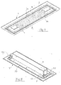
- Figure 1 is a schematic, axonometric bottom view of the recessed lamp structure according to the present invention;
- Figure 2 is an axonometric top view of the recessed lamp structure of Figure 1;
- Figure 3 is a top plan view of the recessed lamp structure according to the present invention;
- Figure 4 is a cross section of the recessed lamp structure of Figure 3 along line IV-IV;
- Figure 5 is a cross section similar to that of Figure 4, but with the plate in an open position.
-
- Referring to Figures 1 and 2, 1 denotes generically a metal frame formed by a
tubular profile 1a and aflange 1b projecting outwardly from one of its ends. It has been indicated at 2 a plate placed in thetubular profile 1a and having a perimeter edge 2a extending perpendicularly therefrom. The shape and size of theplate 2 are substantially the same as those of thetubular profile 1a in such a way that theplate 2, once inserted therein, can close it in a substantially complete manner. - More particularly, in the present embodiment of the invention, the
tubular profile 1a has a rectangular shape and theplate 2 is rotatingly mounted on the frame 1, being able to rotate along an axis parallel to the longer sides. According to the shape of the tubular profile the configuration of the rotating connection between it and theplate 2 will vary in a manner evident to a person skilled in the art. The plate 1 is placed in thetubular profile 1a so as to be substantially coplanar to theflange 1b and the height of its edge 2a is substantially the same as the height of thetubular profile 1a in such a way that the respective free ends are coplanar to the panel forming the false ceiling, the wall or the false wall (denoted by 12 in Figures 4 and 5). - A
window 3, defined by a perimeter wall 4 extending from the same side as the edge 2a and having the same height, is formed on theplate 2. The edge 2a and the wall 4 therefore define acavity 5 on theplate 2. - With reference also to Figures 3, 4 and 5, a box-
shaped body 6 wherein a light source 7 is placed (formed by two tubular elements in the embodiment illustrated in the drawings) and apower supply device 8 connected to the electrical network are mounted on the side of theplate 2 opposite to that where thecavity 5 is formed. The light source 7 is placed at thewindow 3 behind an opaline diffusing panel 9 and is supported by conventional lampholders, not shown, attached to the box-shaped body 6. - The
plate 2 can be hinged to the tubular structure 1 in any suitable known manner. In particular, in the present embodiment of the invention, the pivotable assembly of theplate 2 is achieved by means of a pair ofsquare elements 10, attached by one of their arms along its smaller sides and resting with the other arm on theflange 1b of the tubular framework 1. Theplate 2 is locked in the closure position, i.e. coplanar to theflange 1b, by means of a pressure releasable, snap closure device, generically denoted by 11 and of a known type. The male element 11a of the closure device is attached to theflange 1b, while thefemale element 11b is correspondingly attached to the respective arm of thesquare elements 10 integral with theplate 2. Naturally, equivalent locking devices, for example with a spring, can be used as an alternative. - In the use of the recessed lamp structure according to the present invention, the frame 1 is first engaged in the recessing hole made in the
panel 12, forming a false ceiling, a wall or a false wall, and attached to the latter by means of self-threading screws whose heads are then plastered. Theplate 2, on which the box-shaped body and thesquare elements 10 have already been attached, is inserted in thetubular profile 1a and fastened therein, resting the respective arms of thesquare elements 10 on theflange 1b and locking the plate in a position coplanar to the latter through theclosure device 11. - The
cavity 5 is advantageously filled with the same material constituting thepanel 12 as far as the edge so that, with the installation complete, the only visible gaps in the false ceiling or the wall are thewindow 3 and the narrow slot which remains between thetubular profile 1a and the edge 2a of theplate 2. - The recessed lamp structure according to the present invention is particularly albeit not exclusively designed for use with false ceilings, walls or false walls of considerable thickness, formed for example by panels in covered plasterboard, whose standard thickness is normally 12.5-15-18-20-25 mm. In this case the
cavity 5 is also filled with plasterboard or a similar material. - The
window 3 may have a different shape from that illustrated, also according to the shape and arrangement of the light sources. More particularly its shape may be generically polygonal, circular or elliptical and of any width, even in the form of one or more slots or notches of various lengths and development. - Access for maintenance purposes to the box-
shaped body 6, where the power supply unit and light source are housed, is particularly simple, it being sufficient for this purpose to exert a light pressure from the outside on the plate at the twoclosure devices 11 to actuate their release and allow rotation of the plate outwards through gravity. - Variations and/or modifications may be made to the recessed lamp structure according to the invention, without departing from the scope and spirit of the invention as set forth in the following claims.
Claims (7)
- Recessed lamp structure, suitable for being housed in a recessing hole formed in a panel (12) of a wall, a false ceiling or a false wall, said lamp comprising a light source (7) and a box-shaped support (6) wherein said light source is housed, characterised in that said support is integral with a plate (2) having a window (3) at which said light source is positioned and in that said plate is pivotably mounted on a frame (1) engaged in said recessing hole and attached to said panel, said plate being lockable in a position substantially coplanar to said panel in said frame and having a cavity (5) around said window for housing a shim so as to be flush with said panel.
- Recessed lamp structure according to claim 1, wherein said frame (1) is formed by a tubular profile (1a) and a flange (1b) projecting outwardly from one of its ends, said flange resting on said panel (12) and being attachable to the latter.
- Recessed lamp structure according to claims 1 or 2, wherein said plate (2) has a perimeter edge (2a) extending perpendicular therefrom and the window (3) formed thereon is defined by a perimeter wall extending from the same side as said edge and having substantially the same height as it.
- Recessed lamp structure according to any one of the previous claims, wherein the heights of said tubular profile (1a), of the perimeter edge (2a) of said plate (2) and of the perimeter wall of said window (3) are such that, when said plate (2) is mounted on said frame (1), their respective free ends are coplanar and flush with the external side of said panel (12).
- Recessed lamp structure according to any one of the previous claims, wherein said plate (2) and said tubular profile (1a) have a rectangular shape and said plate is pivotable around an axis parallel to the longer sides, a closure device (11) also being provided, for maintaining said plate (2) in a position substantially coplanar to said flange (1b) .
- Recessed lamp structure according to claim 5, wherein the closure device (11) is of the pressure releasable, snap type or of the spring type or equivalent.
- Recessed lamp structure according to any one of the previous claims, wherein at the two smaller sides of said plate (2) respective square elements (10) are attached by one of their arms, the other arm resting on said flange (1b) .
Applications Claiming Priority (2)
| Application Number | Priority Date | Filing Date | Title |
|---|---|---|---|
| ITFI20040081 | 2004-04-02 | ||
| IT000081A ITFI20040081A1 (en) | 2004-04-02 | 2004-04-02 | BUILT-IN LAMP STRUCTURE |
Publications (2)
| Publication Number | Publication Date |
|---|---|
| EP1582804A2 true EP1582804A2 (en) | 2005-10-05 |
| EP1582804A3 EP1582804A3 (en) | 2008-08-27 |
Family
ID=34878825
Family Applications (1)
| Application Number | Title | Priority Date | Filing Date |
|---|---|---|---|
| EP05102484A Withdrawn EP1582804A3 (en) | 2004-04-02 | 2005-03-30 | Recessed lamp structure |
Country Status (2)
| Country | Link |
|---|---|
| EP (1) | EP1582804A3 (en) |
| IT (1) | ITFI20040081A1 (en) |
Cited By (2)
| Publication number | Priority date | Publication date | Assignee | Title |
|---|---|---|---|---|
| WO2010078741A1 (en) * | 2008-12-29 | 2010-07-15 | Xu Jianguang | Decorative structure of ceiling of building |
| US8115639B2 (en) | 2005-07-29 | 2012-02-14 | Stay Put Systems Limited | Laundry tag |
Family Cites Families (7)
| Publication number | Priority date | Publication date | Assignee | Title |
|---|---|---|---|---|
| US3555668A (en) * | 1966-08-08 | 1971-01-19 | Aluminum Processing Corp | Method of forming a bowl-shaped reflector |
| US4967324A (en) * | 1987-06-26 | 1990-10-30 | Lascon Lighting Industries (Proprietary) Limited | Pivotable luminaire |
| GB2241055A (en) * | 1989-12-28 | 1991-08-21 | Moorlite Electrical Ltd | Structures for mounting lamp fittings |
| JPH0817231A (en) * | 1994-06-30 | 1996-01-19 | Sekisui Chem Co Ltd | lighting equipment |
| IT237980Y1 (en) * | 1997-10-16 | 2000-09-29 | Iguzzini Illuminazione Srl | BOXING FRAME FOR FALSE CEILING SLOTS |
| DE19910469A1 (en) * | 1999-03-10 | 2000-09-21 | Wila Leuchten Ag Sevelen | Luminaire arrangement |
| DE20012688U1 (en) * | 2000-07-21 | 2000-09-21 | RIDI-Leuchten GmbH, 72417 Jungingen | Luminaire arrangement |
-
2004
- 2004-04-02 IT IT000081A patent/ITFI20040081A1/en unknown
-
2005
- 2005-03-30 EP EP05102484A patent/EP1582804A3/en not_active Withdrawn
Non-Patent Citations (1)
| Title |
|---|
| None |
Cited By (2)
| Publication number | Priority date | Publication date | Assignee | Title |
|---|---|---|---|---|
| US8115639B2 (en) | 2005-07-29 | 2012-02-14 | Stay Put Systems Limited | Laundry tag |
| WO2010078741A1 (en) * | 2008-12-29 | 2010-07-15 | Xu Jianguang | Decorative structure of ceiling of building |
Also Published As
| Publication number | Publication date |
|---|---|
| ITFI20040081A1 (en) | 2004-07-02 |
| EP1582804A3 (en) | 2008-08-27 |
Similar Documents
| Publication | Publication Date | Title |
|---|---|---|
| US6530681B2 (en) | Surface-mounted decorative trim ceiling fixture | |
| CA2655346C (en) | Lighting device and lens assembly | |
| TWI422775B (en) | Lamp | |
| US7866843B2 (en) | Corner mounted light fixture | |
| JP2001110228A (en) | Apparatus and method for lighting | |
| CN108386774B (en) | Panel light | |
| EP1582804A2 (en) | Recessed lamp structure | |
| KR200376109Y1 (en) | Frame construction for indirect lighting | |
| US10859242B2 (en) | Downlight for ceiling system | |
| KR20200104482A (en) | Edge type led slim lighting apparatus | |
| JP3968027B2 (en) | Clean room lighting | |
| JPH0332005Y2 (en) | ||
| CN218494849U (en) | Ceiling lamp | |
| JP5695238B2 (en) | LED lighting device | |
| JP2003045221A (en) | Illumination apparatus | |
| CN211925522U (en) | Simple wall lamp | |
| JPH1012022A (en) | Luminaire | |
| JPH079293Y2 (en) | lighting equipment | |
| US11226071B1 (en) | Retrofit light fixture for ceiling swing frame | |
| JPS6328803Y2 (en) | ||
| JPH07320527A (en) | Indirect lighting | |
| JP2617045B2 (en) | lighting equipment | |
| KR200179619Y1 (en) | Inter installation type fluorescence light | |
| JPH0451369Y2 (en) | ||
| JPH0743852Y2 (en) | lighting equipment |
Legal Events
| Date | Code | Title | Description |
|---|---|---|---|
| PUAI | Public reference made under article 153(3) epc to a published international application that has entered the european phase |
Free format text: ORIGINAL CODE: 0009012 |
|
| AK | Designated contracting states |
Kind code of ref document: A2 Designated state(s): AT BE BG CH CY CZ DE DK EE ES FI FR GB GR HU IE IS IT LI LT LU MC NL PL PT RO SE SI SK TR |
|
| AX | Request for extension of the european patent |
Extension state: AL BA HR LV MK YU |
|
| PUAL | Search report despatched |
Free format text: ORIGINAL CODE: 0009013 |
|
| AK | Designated contracting states |
Kind code of ref document: A3 Designated state(s): AT BE BG CH CY CZ DE DK EE ES FI FR GB GR HU IE IS IT LI LT LU MC NL PL PT RO SE SI SK TR |
|
| AX | Request for extension of the european patent |
Extension state: AL BA HR LV MK YU |
|
| AKX | Designation fees paid | ||
| REG | Reference to a national code |
Ref country code: DE Ref legal event code: 8566 |
|
| STAA | Information on the status of an ep patent application or granted ep patent |
Free format text: STATUS: THE APPLICATION IS DEEMED TO BE WITHDRAWN |
|
| 18D | Application deemed to be withdrawn |
Effective date: 20090228 |