EP1582777A2 - Oil propeller wheel and shaft for power transmissions - Google Patents
Oil propeller wheel and shaft for power transmissions Download PDFInfo
- Publication number
- EP1582777A2 EP1582777A2 EP04027541A EP04027541A EP1582777A2 EP 1582777 A2 EP1582777 A2 EP 1582777A2 EP 04027541 A EP04027541 A EP 04027541A EP 04027541 A EP04027541 A EP 04027541A EP 1582777 A2 EP1582777 A2 EP 1582777A2
- Authority
- EP
- European Patent Office
- Prior art keywords
- shaft
- lubricant
- transfer device
- power transfer
- lubricant reservoir
- Prior art date
- Legal status (The legal status is an assumption and is not a legal conclusion. Google has not performed a legal analysis and makes no representation as to the accuracy of the status listed.)
- Granted
Links
Images


Classifications
-
- F—MECHANICAL ENGINEERING; LIGHTING; HEATING; WEAPONS; BLASTING
- F16—ENGINEERING ELEMENTS AND UNITS; GENERAL MEASURES FOR PRODUCING AND MAINTAINING EFFECTIVE FUNCTIONING OF MACHINES OR INSTALLATIONS; THERMAL INSULATION IN GENERAL
- F16H—GEARING
- F16H57/00—General details of gearing
- F16H57/04—Features relating to lubrication or cooling or heating
-
- F—MECHANICAL ENGINEERING; LIGHTING; HEATING; WEAPONS; BLASTING
- F16—ENGINEERING ELEMENTS AND UNITS; GENERAL MEASURES FOR PRODUCING AND MAINTAINING EFFECTIVE FUNCTIONING OF MACHINES OR INSTALLATIONS; THERMAL INSULATION IN GENERAL
- F16H—GEARING
- F16H57/00—General details of gearing
- F16H57/04—Features relating to lubrication or cooling or heating
- F16H57/048—Type of gearings to be lubricated, cooled or heated
- F16H57/0482—Gearings with gears having orbital motion
- F16H57/0483—Axle or inter-axle differentials
-
- B—PERFORMING OPERATIONS; TRANSPORTING
- B60—VEHICLES IN GENERAL
- B60K—ARRANGEMENT OR MOUNTING OF PROPULSION UNITS OR OF TRANSMISSIONS IN VEHICLES; ARRANGEMENT OR MOUNTING OF PLURAL DIVERSE PRIME-MOVERS IN VEHICLES; AUXILIARY DRIVES FOR VEHICLES; INSTRUMENTATION OR DASHBOARDS FOR VEHICLES; ARRANGEMENTS IN CONNECTION WITH COOLING, AIR INTAKE, GAS EXHAUST OR FUEL SUPPLY OF PROPULSION UNITS IN VEHICLES
- B60K17/00—Arrangement or mounting of transmissions in vehicles
- B60K17/34—Arrangement or mounting of transmissions in vehicles for driving both front and rear wheels, e.g. four wheel drive vehicles
- B60K17/344—Arrangement or mounting of transmissions in vehicles for driving both front and rear wheels, e.g. four wheel drive vehicles having a transfer gear
-
- F—MECHANICAL ENGINEERING; LIGHTING; HEATING; WEAPONS; BLASTING
- F16—ENGINEERING ELEMENTS AND UNITS; GENERAL MEASURES FOR PRODUCING AND MAINTAINING EFFECTIVE FUNCTIONING OF MACHINES OR INSTALLATIONS; THERMAL INSULATION IN GENERAL
- F16N—LUBRICATING
- F16N7/00—Arrangements for supplying oil or unspecified lubricant from a stationary reservoir or the equivalent in or on the machine or member to be lubricated
- F16N7/14—Arrangements for supplying oil or unspecified lubricant from a stationary reservoir or the equivalent in or on the machine or member to be lubricated the lubricant being conveyed from the reservoir by mechanical means
- F16N7/16—Arrangements for supplying oil or unspecified lubricant from a stationary reservoir or the equivalent in or on the machine or member to be lubricated the lubricant being conveyed from the reservoir by mechanical means the oil being carried up by a lifting device
- F16N7/18—Arrangements for supplying oil or unspecified lubricant from a stationary reservoir or the equivalent in or on the machine or member to be lubricated the lubricant being conveyed from the reservoir by mechanical means the oil being carried up by a lifting device with one or more feed members fixed on a shaft
-
- F—MECHANICAL ENGINEERING; LIGHTING; HEATING; WEAPONS; BLASTING
- F16—ENGINEERING ELEMENTS AND UNITS; GENERAL MEASURES FOR PRODUCING AND MAINTAINING EFFECTIVE FUNCTIONING OF MACHINES OR INSTALLATIONS; THERMAL INSULATION IN GENERAL
- F16H—GEARING
- F16H57/00—General details of gearing
- F16H57/04—Features relating to lubrication or cooling or heating
- F16H57/042—Guidance of lubricant
- F16H57/0427—Guidance of lubricant on rotary parts, e.g. using baffles for collecting lubricant by centrifugal force
- F16H57/0428—Grooves with pumping effect for supplying lubricants
Definitions
- the present invention relates to power transmission devices for use in automotive vehicles and more particularly to lubrication mechanisms for delivering lubrication to predetermined locations within a power transmission device.
- Lubrication is important for many mechanical systems. Lubrication may be employed in a given mechanical system to reduce the operating temperature, reduce noise level, reduce contact resistance of inter-working components, and increase overall longevity of the mechanical system.
- a power transfer device includes a casing, a lubricant reservoir in the casing and a shaft rotatably supported in the casing.
- the shaft extends into the lubricant reservoir, the lubricant reservoir having lubricant therein.
- a lubricant driving structure is coupled to the shaft for common rotation therewith.
- the lubricant driving structure includes at least one helically shaped member that extends longitudinally along and circumferentially about at least a portion of the shaft.
- the at least one helically shaped member is at least partially located in the lubricant reservoir. Rotation of the at least one helically shaped member drives a portion of the lubricant in an axial direction along the shaft and away from the lubricant reservoir.
- the at least one helically-shaped member comprises a plurality of circumferentially-spaced apart teeth that extend outwardly of the shaft.
- the teeth taper radially outwardly along a direction that is generally opposite an axial direction in which the portion of the lubricant is driven.
- the at least one helically shaped member is integrally formed with the shaft.
- the shaft extends into a hole formed into another component of the power transfer device and the at least one helically shaped member terminates axially along the shaft prior to a point at which the shaft enters the hole.
- a power transfer device includes a casing and a lubricant reservoir in the casing, the lubricant reservoir having lubricant therein.
- a shaft is rotatably supported within the casing and extends into the lubricant reservoir.
- a differential assembly is coupled to the shaft.
- An oil propeller wheel is fixedly mounted around the shaft for rotation therewith. The oil propeller wheel communicates with the lubrication in the lubricant reservoir and is operable to direct a portion of the lubricant from the lubricant reservoir in a direction axially along the shaft and toward the differential assembly.
- the shaft extends through a hold in the first member, the first member having a recessed portion for accommodating the oil propeller wheel.
- An annular space is defined between the first member and the shaft. The annular space forms a passage for delivering the lubrication from the oil propeller wheel to the differential assembly.
- the oil propeller wheel includes a main body portion having gear type teeth disposed radially therearound.
- the gear type teeth extend from a first end of the main body portion to a wall portion formed at a second end of the main body portion.
- the gear type teeth extend in a generally helical pattern tapering outwardly and defining blade portions from the first end of the body portion to the second end of the body portion.
- the wall portion is operable to inhibit lubrication from flowing from the second end portion in a direction away from the first end portion.
- the casing defines a passage adapted to deliver the lubricant from an area adjacent the differential assembly to the lubricant reservoir.
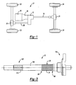
- FIG. 1 is a schematic view of an exemplary motor vehicle having an exemplary transfer case into which an oil propeller shaft and oil propeller wheel constructed in accordance with the teachings of the present invention are incorporated;
- FIG. 2 is a cross-sectional view of the transfer case of FIG. 1;
- FIG. 3 is a side view of a portion of the transfer case of FIG. 1 illustrating the oil propeller shaft;
- FIG. 4 is an enlarged view of the oil propeller shaft illustrating the threaded intermediate portion
- FIG. 5 is a cross-sectional view of the threaded intermediate view taken along line 5 - 5 of FIG. 4;
- FIG. 6 is a cross-sectional view of the exemplary transfer case of FIG. 1 incorporating an oil propeller wheel constructed in accordance with the teachings of the present invention
- FIG. 7 is an axial end view of the oil propeller wheel of FIG. 6.
- FIG. 8 is a cross-sectional view of the oil propeller wheel taken along line 8 - 8 of FIG. 7.
- a power transfer device or transfer case 10 constructed in accordance with the teachings of the present invention is shown in conjunction with an exemplary motor vehicle 12. While the power transfer device has been shown as a transfer case 10 assembly for exemplary purposes, those of ordinary skill in the art as will readily appreciate from the following discussion, that the power transfer device may be otherwise configured. As such, the scope of the present invention is not limited by the particular example provided but rather includes devices including, but not limited to, transmissions, differentials, axles, and power-take-offs.
- the vehicle 12 may include an engine 18 and a transmission 16.
- the transfer case 10 may be coupled to the transmission 16, which in turn operably coupled to the engine 18.
- a first propeller shaft 19 may be employed to transmit rotary power between the transfer case 10 and a first axle 21 for driving a first set of drive wheels 24.
- a second propeller shaft 26 may be employed to transmit rotary power between the transfer case 10 and a second axle 28 for driving a second set of drive wheels 30.
- the engine 18 produces drive torque that may be communicated to the transfer case 10 through a plurality of selectively engagable gear ratios that are provided by the transmission 16.
- the transfer case 10 may receive drive torque from the transmission 16 and selectively distribute rotary power to the first and second set of drive wheels 24 and 30. In this way, the transfer case 10 may be configured to provide an "on-demand" four-wheel-drive mode, providing rear or front wheel drive as a default operation and providing power to all four wheels when necessary. Alternatively, the transfer case 10 may be configured to provide a four-wheel-drive mode controlled automatically or by a vehicle operator.
- the transfer case 10 includes a shaft, such as the first output shaft 20, that may include an intermediate threaded portion 34 for facilitating lubrication within the transfer case 10 as will be described in greater detail herein.
- the intermediate threaded portion 34 is formed around a circumferential surface 36 of the first output shaft 20.
- the transfer case 10 may comprise a casing 40, an input shaft 42, a differential assembly 44, the first output shaft 20 and a second output shaft 48.
- the input shaft 42 may be drivingly connected to an output shaft (not shown) of the transmission 16 and is rotatably supported in the casing 40 by a bearing assembly 50.
- the first output shaft 20 is configured to transmit rotary power for driving the first set of drive wheels 24, or rear drive wheels as depicted in FIG. 1.
- the second output shaft 48 is configured to transmit rotary power for driving the second set of drive wheels 30, or front drive wheels as depicted in FIG. 1.
- the first output shaft 20 may be rotatably supported in the casing 40 by any appropriate means, such as a bearing assembly 54 and a needle bearing or bushing 72.
- the second output shaft 48 may also be rotatably supported in the casing 40 by any appropriate means, such as a pair of bearing assemblies 56.
- a torque transfer mechanism 60 is disposed in the transfer case 10 for selectively transferring drive torque from the differential assembly 44 to the second output shaft 48.
- the torque transfer mechanism 60 generally comprises a first drive sprocket 62 rotatably mounted about the first output shaft 20, a second driven sprocket 64 rotatably mounted to the second output shaft 48 and a torque transfer element 70, such as a chain or belt, interconnecting the sprockets 62 and 64.
- the first drive sprocket 62 has a pocket 76 that defines an annular space 74 about at least a portion of the threaded portion 34 of the first output shaft 20.
- the differential casing 40 may define a wall 80 adjacent to the transfer mechanism 60 and proximate to the drive sprocket 62.
- the wall 80 defines a lubricant reservoir 82 that is interconnected to at least one fluid passage 84.
- the lubricant reservoir 82 which may be defined by the casing 40, the shield bearings 54 and 58, and the drive sprocket 62, is adapted to store a predetermined amount of lubricant, such as oil, that is used for lubricating the differential assembly 44, the needle bearing or bushing 72 and the bearing assembly 50.
- the lubricant reservoir 82 may be sealed at the shield bearings 54 and 58 by seals 83.
- the intermediate threaded portion 34 of the first output shaft 20 extends into the lubricant reservoir 82 for communicating with the lubricant therein. More specifically, the threaded portion 34 defines an entry portion 86 on a first end, which is in communication with the lubricant reservoir 82, and a delivery portion 88 on a second end.
- the threaded portion 34 has a profile whereby rotation of the first output shaft 20 causes lubricant at the lubricant reservoir 82 to be directed axially along the threaded portion 34 toward the delivery portion 88 (leftward as viewed from FIG. 2). In this way, the threaded portion 34 of the first output shaft 20 urges lubrication in a direction toward the differential assembly 44.
- the lubrication passes through the annular space 74 and into the differential assembly 44 by way of an inlet path 90.
- the inlet path 90 is a space between the first output shaft 20 and an output of the differential assembly 44 that is coupled to the first drive sprocket 62.
- lubrication within the differential assembly 44 is forced through the oil passages 98 and the clearance 66 between the drive sprocket 62 and the differential assembly 44. From there, the lubricant may flow into an inner cavity 94, then through an oil passage 96 and back into the inner cavity 92 of the casing 40 proximate the driven sprocket 64. The lubricant may be forced out from the differential assembly 44 through the oil passages 98 to lubricate the bearing assembly 50. The lubrication, drawing from the inner cavity 92, may be splashed onto the drive sprocket 62 and the torque transfer element 70 and thereafter may pass through the fluid passage 84 and into the lubrication reservoir 82 whereby the cycle is repeated.
- the first output shaft 20 generally comprises a longitudinal shaft member 100 having first end portion 102, a second end portion 104 and the intermediate threaded portion 34.
- the first end portion 102 may include splines 110 for engaging complementary splines (not specifically shown) formed on the differential assembly 44.
- the second end portion 104 may have any desired configuration that permits it to transmit rotary power to the first prop shaft 19 (FIG. 1) for transmitting rotary motion to the first set of drive wheels 24 (FIG. 1).
- the threaded portion 34 is in the form of a continuous helically shaped member defining helical worm teeth 112 for communicating fluid in a desired direction (e.g., leftward as viewed in FIG. 4) to deliver lubrication to a desired location.
- a desired direction e.g., leftward as viewed in FIG. 4
- the helical worm teeth 112 each define a driving face 120 oriented on a forward side of the teeth 112.
- the respective driving faces 120 contact the lubrication to urge it axially along the output shaft 20 toward the differential assembly 44.
- the profile of the teeth 112 defines a pressure angle ⁇ (FIG. 5).
- the pressure angle ⁇ shown on the exemplary threaded portion 34 may comprise various angles.
- the fluid delivering capacity and capability of the threaded portion 34 increases as the pressure angle decreases.
- the lubrication transferring efficiency is controlled by many factors such as, the number of continuous teeth 112, the length of the threaded potion 34, the pressure angle ⁇ , the tooth pitch, and surface finish of the teeth 112 for example.
- FIG. 6 a second exemplary power transfer device, which may be a transfer case 200, incorporating an oil propeller wheel 202 according to other features of the present invention is shown.
- the transfer case 200 includes like components as described in relation to the transfer case 10 and as such, these components are designated with like reference numerals with two hundred (200) added thereto.
- the oil propeller wheel 202 is described in relation with a transfer case 200, the teachings of the present invention may be applied to other mechanical systems and power transfer devices for distributing lubrication to a working element.
- the transfer case 200 includes an input shaft 242, a differential assembly 244, a first output shaft 220 and a second output shaft 248.
- a torque transfer mechanism 260 generally comprises a first drive sprocket 262 rotatably mounted about the first output shaft 220, a second driven sprocket 264 rotatably mounted to the second output shaft 248 and a torque transfer element 270 interconnecting the sprockets 262 and 264.
- the differential casing 240 defines a wall 280 adjacent to the transfer mechanism 270 and proximate to the drive sprocket 262. This wall 280 defines a lubricant reservoir 282 that may be interconnected to at least one fluid passage 284.
- the lubrication reservoir 282 which may be defined by the casing 240, shield bearings 254 and 258, and the drive sprocket 262, is adapted to store a lubricant, such as oil, used for lubricating the differential assembly 244, the needle bearing or bushing 272, and the bearing assembly 250.
- the lubricant reservoir 282 may be sealed at the shield bearings 254 and 258 by seals 283.
- the oil propeller wheel 202 is mounted around an intermediate portion 234 of the first output shaft 220 and may be disposed in the lubricant of the lubricant reservoir 282.
- the oil propeller wheel 202 is securely attached to the first output shaft 220 for common rotation therewith.
- the oil propeller wheel 202 is operable to direct lubrication from the lubricant reservoir 282, through an annular space 274 provided between the first output shaft 220 and the drive sprocket 262 of the transfer mechanism 270 and into the differential assembly 244.
- the drive sprocket 262 may include a recess 278 for accommodating the oil propeller wheel 202.
- the oil propeller wheel 202 rotates with the first output shaft 220.
- the oil propeller wheel 202 causes lubrication to flow from the lubrication reservoir 282 in a desired direction (e.g., leftward as viewed in FIG. 6) to deliver lubrication to a desired location, such as the differential assembly 244.
- a desired direction e.g., leftward as viewed in FIG. 6
- excess lubrication exits the differential assembly 244 is forced through oil passages 298 and the clearance 266 between the drive sprocket 262 and the differential assembly 244 into the inner cavity 294, then through an oil passage 296, and back into the inner cavity 292 of the casing 240 proximate the driven sprocket 264.
- the lubrication may be forced out of the differential assembly 244 through the oil passages 298 to lubricate the bearing 250 assembly.
- the lubrication drawing from the inner cavity, may be splashed onto the drive sprocket 262 and the torque transfer element 270 and thereafter may pass through the fluid passage 284 and into the lubrication reservoir 282 whereby the cycle is repeated.
- the oil propeller wheel 202 generally includes a main body 300 having a plurality of helically-shaped circumferentially spaced-apart teeth 310 extending radially outwardly from the main body 300.
- the gear type teeth 310 may extend from a first axial end 312 of the body 300 to a wall portion 316 formed at a second axial end 320 of the body 300.
- the teeth 310 may be generally helical in shape and may taper in a radially outward direction between the ends 312 and 316 so as to define a blade portion 322 from the first end 312 of the body 300 to the second end 320 of the body 300.
- the teeth 310 may be arranged in a "right-hand" helical pattern as viewed from FIG. 7. Rotation of the propeller wheel 202 in the direction of arrow R' causes the helical blade portions 322 of the teeth 310 to urge lubrication toward the differential assembly (FIG. 6).
- the wall 316 inhibits lubrication from passing rightward beyond the body 300 and toward the bearing assembly 254 (FIG. 6).
- the oil propeller wheel 202 is comprised of a rigid material such as metal or plastic. It may be machined from metal such as cast iron or aluminum. Alternatively, it may be molded or cast from metal, powdered metal or plastic.
- the oil propeller wheel 202 may be rigidly attached to the first output gear 220 by any suitable mounting techniques, such as, but not limited to, fasteners such as a key or dowel for example, press-fit or splined with the first output shaft 220.
Landscapes
- Engineering & Computer Science (AREA)
- General Engineering & Computer Science (AREA)
- Mechanical Engineering (AREA)
- Chemical & Material Sciences (AREA)
- Combustion & Propulsion (AREA)
- Transportation (AREA)
- General Details Of Gearings (AREA)
- Arrangement And Driving Of Transmission Devices (AREA)
Abstract
Description
- The present invention relates to power transmission devices for use in automotive vehicles and more particularly to lubrication mechanisms for delivering lubrication to predetermined locations within a power transmission device.
- Effective oil lubrication is important for many mechanical systems. Lubrication may be employed in a given mechanical system to reduce the operating temperature, reduce noise level, reduce contact resistance of inter-working components, and increase overall longevity of the mechanical system.
- Many conventional mechanical systems, such as transmissions and transfer cases, incorporate an oil pump to facilitate lubrication to desired components. Alternatively, some mechanical systems may incorporate splash lubrication whereby oil is splashed onto a desired bearing or component by a gear or simple rotating disk incorporated in the mechanical system proximate the desired component.
- While such arrangements are satisfactory for their intended purpose, a need exists to develop simpler, more cost-effective alternatives that provide the desired function while advancing the art.
- A power transfer device includes a casing, a lubricant reservoir in the casing and a shaft rotatably supported in the casing. The shaft extends into the lubricant reservoir, the lubricant reservoir having lubricant therein. A lubricant driving structure is coupled to the shaft for common rotation therewith. The lubricant driving structure includes at least one helically shaped member that extends longitudinally along and circumferentially about at least a portion of the shaft. The at least one helically shaped member is at least partially located in the lubricant reservoir. Rotation of the at least one helically shaped member drives a portion of the lubricant in an axial direction along the shaft and away from the lubricant reservoir.
- According to other features, the at least one helically-shaped member comprises a plurality of circumferentially-spaced apart teeth that extend outwardly of the shaft. The teeth taper radially outwardly along a direction that is generally opposite an axial direction in which the portion of the lubricant is driven. The at least one helically shaped member is integrally formed with the shaft. The shaft extends into a hole formed into another component of the power transfer device and the at least one helically shaped member terminates axially along the shaft prior to a point at which the shaft enters the hole.
- A power transfer device includes a casing and a lubricant reservoir in the casing, the lubricant reservoir having lubricant therein. A shaft is rotatably supported within the casing and extends into the lubricant reservoir. A differential assembly is coupled to the shaft. An oil propeller wheel is fixedly mounted around the shaft for rotation therewith. The oil propeller wheel communicates with the lubrication in the lubricant reservoir and is operable to direct a portion of the lubricant from the lubricant reservoir in a direction axially along the shaft and toward the differential assembly.
- According to other features, the shaft extends through a hold in the first member, the first member having a recessed portion for accommodating the oil propeller wheel. An annular space is defined between the first member and the shaft. The annular space forms a passage for delivering the lubrication from the oil propeller wheel to the differential assembly.
- According to still other features, the oil propeller wheel includes a main body portion having gear type teeth disposed radially therearound. The gear type teeth extend from a first end of the main body portion to a wall portion formed at a second end of the main body portion. The gear type teeth extend in a generally helical pattern tapering outwardly and defining blade portions from the first end of the body portion to the second end of the body portion. The wall portion is operable to inhibit lubrication from flowing from the second end portion in a direction away from the first end portion. The casing defines a passage adapted to deliver the lubricant from an area adjacent the differential assembly to the lubricant reservoir.
- Further areas of applicability of the present invention will become apparent from the detailed description provided hereinafter. It should be understood that the detailed description and specific examples, while indicating the preferred embodiment of the invention, are intended for purposes of illustration only and are not intended to limit the scope of the invention.
- The present invention will become more fully understood from the detailed description and the accompanying drawings, wherein:
- FIG. 1 is a schematic view of an exemplary motor vehicle having an exemplary transfer case into which an oil propeller shaft and oil propeller wheel constructed in accordance with the teachings of the present invention are incorporated;
- FIG. 2 is a cross-sectional view of the transfer case of FIG. 1;
- FIG. 3 is a side view of a portion of the transfer case of FIG. 1 illustrating the oil propeller shaft;
- FIG. 4 is an enlarged view of the oil propeller shaft illustrating the threaded intermediate portion;
- FIG. 5 is a cross-sectional view of the threaded intermediate view taken along line 5 - 5 of FIG. 4;
- FIG. 6 is a cross-sectional view of the exemplary transfer case of FIG. 1 incorporating an oil propeller wheel constructed in accordance with the teachings of the present invention;
- FIG. 7 is an axial end view of the oil propeller wheel of FIG. 6; and
- FIG. 8 is a cross-sectional view of the oil propeller wheel taken along line 8 - 8 of FIG. 7.
- The following description of the preferred embodiment(s) is merely exemplary in nature and is in no way intended to limit the invention, its application, or uses. The differential assembly according to the present teachings may be utilized with a wide variety of applications and is not intended to be specifically limited to the particular application recited herein.
- With initial reference to FIG. 1, a power transfer device or
transfer case 10 constructed in accordance with the teachings of the present invention is shown in conjunction with anexemplary motor vehicle 12. While the power transfer device has been shown as atransfer case 10 assembly for exemplary purposes, those of ordinary skill in the art as will readily appreciate from the following discussion, that the power transfer device may be otherwise configured. As such, the scope of the present invention is not limited by the particular example provided but rather includes devices including, but not limited to, transmissions, differentials, axles, and power-take-offs. - The
vehicle 12 may include anengine 18 and atransmission 16. Thetransfer case 10 may be coupled to thetransmission 16, which in turn operably coupled to theengine 18. Afirst propeller shaft 19 may be employed to transmit rotary power between thetransfer case 10 and afirst axle 21 for driving a first set ofdrive wheels 24. Asecond propeller shaft 26 may be employed to transmit rotary power between thetransfer case 10 and a second axle 28 for driving a second set ofdrive wheels 30. Theengine 18 produces drive torque that may be communicated to thetransfer case 10 through a plurality of selectively engagable gear ratios that are provided by thetransmission 16. - The
transfer case 10 may receive drive torque from thetransmission 16 and selectively distribute rotary power to the first and second set ofdrive wheels transfer case 10 may be configured to provide an "on-demand" four-wheel-drive mode, providing rear or front wheel drive as a default operation and providing power to all four wheels when necessary. Alternatively, thetransfer case 10 may be configured to provide a four-wheel-drive mode controlled automatically or by a vehicle operator. - With continued reference to FIG. 1 and further reference to FIGS. 2 and 3, the
transfer case 10 includes a shaft, such as thefirst output shaft 20, that may include an intermediate threadedportion 34 for facilitating lubrication within thetransfer case 10 as will be described in greater detail herein. The intermediate threadedportion 34 is formed around acircumferential surface 36 of thefirst output shaft 20. - The
transfer case 10 may comprise acasing 40, aninput shaft 42, adifferential assembly 44, thefirst output shaft 20 and asecond output shaft 48. Theinput shaft 42 may be drivingly connected to an output shaft (not shown) of thetransmission 16 and is rotatably supported in thecasing 40 by abearing assembly 50. In theexemplary transfer case 10, thefirst output shaft 20 is configured to transmit rotary power for driving the first set ofdrive wheels 24, or rear drive wheels as depicted in FIG. 1. Likewise, thesecond output shaft 48 is configured to transmit rotary power for driving the second set ofdrive wheels 30, or front drive wheels as depicted in FIG. 1. Thefirst output shaft 20 may be rotatably supported in thecasing 40 by any appropriate means, such as abearing assembly 54 and a needle bearing or bushing 72. Thesecond output shaft 48 may also be rotatably supported in thecasing 40 by any appropriate means, such as a pair of bearingassemblies 56. - A
torque transfer mechanism 60 is disposed in thetransfer case 10 for selectively transferring drive torque from thedifferential assembly 44 to thesecond output shaft 48. Thetorque transfer mechanism 60 generally comprises afirst drive sprocket 62 rotatably mounted about thefirst output shaft 20, a second drivensprocket 64 rotatably mounted to thesecond output shaft 48 and atorque transfer element 70, such as a chain or belt, interconnecting thesprockets first drive sprocket 62 has apocket 76 that defines anannular space 74 about at least a portion of the threadedportion 34 of thefirst output shaft 20. - The
differential casing 40 may define awall 80 adjacent to thetransfer mechanism 60 and proximate to thedrive sprocket 62. Thewall 80 defines alubricant reservoir 82 that is interconnected to at least onefluid passage 84. Thelubricant reservoir 82, which may be defined by thecasing 40, theshield bearings drive sprocket 62, is adapted to store a predetermined amount of lubricant, such as oil, that is used for lubricating thedifferential assembly 44, the needle bearing orbushing 72 and the bearingassembly 50. Thelubricant reservoir 82 may be sealed at theshield bearings - The intermediate threaded
portion 34 of thefirst output shaft 20 extends into thelubricant reservoir 82 for communicating with the lubricant therein. More specifically, the threadedportion 34 defines anentry portion 86 on a first end, which is in communication with thelubricant reservoir 82, and adelivery portion 88 on a second end. The threadedportion 34 has a profile whereby rotation of thefirst output shaft 20 causes lubricant at thelubricant reservoir 82 to be directed axially along the threadedportion 34 toward the delivery portion 88 (leftward as viewed from FIG. 2). In this way, the threadedportion 34 of thefirst output shaft 20 urges lubrication in a direction toward thedifferential assembly 44. The lubrication passes through theannular space 74 and into thedifferential assembly 44 by way of aninlet path 90. In the example shown, theinlet path 90 is a space between thefirst output shaft 20 and an output of thedifferential assembly 44 that is coupled to thefirst drive sprocket 62. - As lubrication is urged into the
differential assembly 44, lubrication within thedifferential assembly 44 is forced through theoil passages 98 and theclearance 66 between thedrive sprocket 62 and thedifferential assembly 44. From there, the lubricant may flow into aninner cavity 94, then through anoil passage 96 and back into theinner cavity 92 of thecasing 40 proximate the drivensprocket 64. The lubricant may be forced out from thedifferential assembly 44 through theoil passages 98 to lubricate the bearingassembly 50. The lubrication, drawing from theinner cavity 92, may be splashed onto thedrive sprocket 62 and thetorque transfer element 70 and thereafter may pass through thefluid passage 84 and into thelubrication reservoir 82 whereby the cycle is repeated. - With reference to FIG. 3, the
first output shaft 20 will be described in greater detail. Thefirst output shaft 20 generally comprises alongitudinal shaft member 100 havingfirst end portion 102, asecond end portion 104 and the intermediate threadedportion 34. Thefirst end portion 102 may includesplines 110 for engaging complementary splines (not specifically shown) formed on thedifferential assembly 44. Thesecond end portion 104 may have any desired configuration that permits it to transmit rotary power to the first prop shaft 19 (FIG. 1) for transmitting rotary motion to the first set of drive wheels 24 (FIG. 1). - With reference to FIGS. 4 and 5, the detail of an exemplary threaded
portion 34 is shown. Specifically, the threadedportion 34 is in the form of a continuous helically shaped member defininghelical worm teeth 112 for communicating fluid in a desired direction (e.g., leftward as viewed in FIG. 4) to deliver lubrication to a desired location. In the example provided thefirst output shaft 20 rotates in the direction of arrow R. Thehelical worm teeth 112 each define a drivingface 120 oriented on a forward side of theteeth 112. The respective driving faces 120 contact the lubrication to urge it axially along theoutput shaft 20 toward thedifferential assembly 44. The profile of theteeth 112 defines a pressure angle α (FIG. 5). The pressure angle α shown on the exemplary threadedportion 34 may comprise various angles. For example, the threadedportion 34 may comprise square teeth presenting a constant pressure angle α = 0°, generally V-shaped teeth which present a constant pressure angle that is greater than 0° and less than 180°, or comprise curved teeth, such as those shown in FIGS. 4 and 5, having a variable pressure angle. In practice, the fluid delivering capacity and capability of the threadedportion 34 increases as the pressure angle decreases. The lubrication transferring efficiency is controlled by many factors such as, the number ofcontinuous teeth 112, the length of the threadedpotion 34, the pressure angle α, the tooth pitch, and surface finish of theteeth 112 for example. - Turning now to FIG. 6, a second exemplary power transfer device, which may be a
transfer case 200, incorporating anoil propeller wheel 202 according to other features of the present invention is shown. Thetransfer case 200 includes like components as described in relation to thetransfer case 10 and as such, these components are designated with like reference numerals with two hundred (200) added thereto. Again, as will become readily appreciated from the following discussion, while theoil propeller wheel 202 is described in relation with atransfer case 200, the teachings of the present invention may be applied to other mechanical systems and power transfer devices for distributing lubrication to a working element. - The
transfer case 200 includes an input shaft 242, adifferential assembly 244, afirst output shaft 220 and asecond output shaft 248. Atorque transfer mechanism 260 generally comprises afirst drive sprocket 262 rotatably mounted about thefirst output shaft 220, a second drivensprocket 264 rotatably mounted to thesecond output shaft 248 and atorque transfer element 270 interconnecting thesprockets differential casing 240 defines awall 280 adjacent to thetransfer mechanism 270 and proximate to thedrive sprocket 262. Thiswall 280 defines alubricant reservoir 282 that may be interconnected to at least onefluid passage 284. Thelubrication reservoir 282, which may be defined by thecasing 240,shield bearings drive sprocket 262, is adapted to store a lubricant, such as oil, used for lubricating thedifferential assembly 244, the needle bearing or bushing 272, and the bearingassembly 250. Thelubricant reservoir 282 may be sealed at theshield bearings seals 283. - The
oil propeller wheel 202 is mounted around anintermediate portion 234 of thefirst output shaft 220 and may be disposed in the lubricant of thelubricant reservoir 282. Theoil propeller wheel 202 is securely attached to thefirst output shaft 220 for common rotation therewith. As will be described, theoil propeller wheel 202 is operable to direct lubrication from thelubricant reservoir 282, through anannular space 274 provided between thefirst output shaft 220 and thedrive sprocket 262 of thetransfer mechanism 270 and into thedifferential assembly 244. Thedrive sprocket 262 may include arecess 278 for accommodating theoil propeller wheel 202. - During operation, the
oil propeller wheel 202 rotates with thefirst output shaft 220. Theoil propeller wheel 202 causes lubrication to flow from thelubrication reservoir 282 in a desired direction (e.g., leftward as viewed in FIG. 6) to deliver lubrication to a desired location, such as thedifferential assembly 244. As lubrication is urged into thedifferential assembly 244, excess lubrication exits thedifferential assembly 244 is forced throughoil passages 298 and theclearance 266 between thedrive sprocket 262 and thedifferential assembly 244 into theinner cavity 294, then through anoil passage 296, and back into theinner cavity 292 of thecasing 240 proximate the drivensprocket 264. The lubrication may be forced out of thedifferential assembly 244 through theoil passages 298 to lubricate thebearing 250 assembly. The lubrication, drawing from the inner cavity, may be splashed onto thedrive sprocket 262 and thetorque transfer element 270 and thereafter may pass through thefluid passage 284 and into thelubrication reservoir 282 whereby the cycle is repeated. - With reference to FIGS. 7 and 8, the
oil propeller wheel 202 will be described in greater detail. Theoil propeller wheel 202 generally includes amain body 300 having a plurality of helically-shaped circumferentially spaced-apartteeth 310 extending radially outwardly from themain body 300. Thegear type teeth 310 may extend from a firstaxial end 312 of thebody 300 to awall portion 316 formed at a secondaxial end 320 of thebody 300. Theteeth 310 may be generally helical in shape and may taper in a radially outward direction between theends blade portion 322 from thefirst end 312 of thebody 300 to thesecond end 320 of thebody 300. - The
teeth 310 may be arranged in a "right-hand" helical pattern as viewed from FIG. 7. Rotation of thepropeller wheel 202 in the direction of arrow R' causes thehelical blade portions 322 of theteeth 310 to urge lubrication toward the differential assembly (FIG. 6). When the first output shaft 220 (FIG. 6) is rotating in a clockwise direction (for example when the vehicle is operated in reverse), thewall 316 inhibits lubrication from passing rightward beyond thebody 300 and toward the bearing assembly 254 (FIG. 6). It will be appreciated from the disclosures that the "hand" of the helical lubrication moving element may be set for a desired application and as such, the scope of the present invention is not limited by the particular examples shown. - The
oil propeller wheel 202 is comprised of a rigid material such as metal or plastic. It may be machined from metal such as cast iron or aluminum. Alternatively, it may be molded or cast from metal, powdered metal or plastic. Theoil propeller wheel 202 may be rigidly attached to thefirst output gear 220 by any suitable mounting techniques, such as, but not limited to, fasteners such as a key or dowel for example, press-fit or splined with thefirst output shaft 220. - While the invention has been described in the specification and illustrated in the drawings with reference to various embodiments, it will be understood by those skilled in the art that various changes may be made and equivalents may be substituted for elements thereof without departing from the scope of the invention as defined in the claims. Furthermore, the mixing and matching of features, elements and/or functions between various embodiments is expressly contemplated herein so that one of ordinary skill in the art would appreciate from this disclosure that features, elements and/or functions of one embodiment may be incorporated into another embodiment as appropriate, unless described otherwise above. Moreover, many modifications may be made to adapt a particular situation or material to the teachings of the invention without departing from the essential scope thereof. Therefore, it is intended that the invention not be limited to the particular embodiment illustrated by the drawings and described in the specification as the best mode presently contemplated for carrying out this invention, but that the invention will include any embodiments falling within the foregoing description and the appended claims.
Claims (21)
- A power transfer device comprising:wherein rotation of said at least one helically shaped member drives a portion of said lubricant in an axial direction along said shaft and away from said lubricant reservoir.a casing;a lubricant reservoir in said casing;a shaft rotatably supported in said casing, the shaft extending into said lubricant reservoir;a lubricant in said lubricant reservoir; anda lubricant driving structure coupled to said shaft for common rotation therewith, the lubricant driving structure including at least one helically shaped member that extends longitudinally along and circumferentially about at least a portion of said shaft, said at least one helically shaped member being at least partially located in said lubricant reservoir;
- A power transfer device of Claim 1, wherein said at least one helically-shaped member comprises a plurality of circumferentially-spaced apart teeth that extend radially outwardly of said shaft.
- A power transfer device of Claim 2, wherein said teeth taper radially outwardly along a direction that is generally opposite an axial direction in which the portion of the lubricant is driven.
- A power transfer device of Claim 1 wherein said at least one helically shaped member is integrally formed with the shaft.
- A power transfer device of Claim 1, wherein said shaft extends into a hole formed into another component of the power transfer device and wherein said at least one helically shaped member terminates axially along said shaft prior to a point at which said shaft enters said hole.
- The power transfer device of Claim 5, wherein a recessed area is formed into said another component about said hole.
- The power transfer device of Claim 1, wherein said shaft extends into a hole formed into another component of the power transfer device and wherein said at least one helically shaped member extends through said hole.
- A power transfer device comprising:wherein said shaft includes threads defined along a circumferential surface thereof, said threads operable to direct a portion of said lubricant from said lubricant reservoir in a direction axially along said shaft and toward said differential assembly.a casing;a lubricant reservoir in said casing;a lubricant in said lubricant reservoir;a shaft rotatably supported within said casing and extending into said lubricant reservoir;a differential assembly coupled to said shaft;
- The power transfer device of claim 8 wherein said input shaft is mounted for rotation within a structure, said structure being spaced radially apart from said threads to form a fluid passage.
- The power transfer device of claim 8 wherein said threads are formed along an intermediate portion of said output shaft and define an entry portion wherein said lubricant comes into contact with said threads and a delivery portion wherein said lubricant is output in a direction toward said differential assembly.
- The power transfer device of claim 10 wherein said casing defines a passage adapted to permit said lubricant to return to said lubricant reservoir from said differential assembly.
- The power transfer device of claim 11 wherein said entry portion of said threads is disposed in said fluid reservoir.
- The power transfer device of claim 12 wherein said passage delivers lubricant to said lubricant reservoir proximate said entry portion of said threads.
- A power transfer device comprising:a casing;a lubricant reservoir in said casing;a lubricant in said lubricant reservoir;a shaft rotatably supported within said casing and extending into said lubricant reservoir;a differential assembly coupled to said shaft;an oil propeller wheel fixedly mounted around said shaft for rotation therewith, said oil propeller wheel communicating with said lubrication in said lubricant reservoir and operable to direct a portion of said lubricant from said lubricant reservoir in a direction axially along said shaft and toward said differential assembly.
- The power transfer device of claim 14 wherein said shaft extends through a hole in a first member, the first member having a recessed portion for accommodating said oil propeller wheel.
- The power transfer device of claim 16 wherein an annular space is defined between said first member and said shaft, the annular space forming a passage for delivering said lubrication from said oil propeller wheel to said differential assembly.
- The power transfer device of claim 16 wherein said oil propeller wheel includes a main body portion having gear type teeth disposed radially therearound.
- The power transfer device of claim 17 wherein said gear type teeth extend from a first end of said main body portion to a wall portion formed at a second end of said main body portion.
- The power transfer device of claim 18 wherein said gear type teeth extend in a generally helical pattern tapering outwardly and defining blade portions from said first end of said body portion to said second end of said body portion.
- The power transfer device of claim 18 wherein said wall portion is operable to inhibit lubrication from flowing from said second end portion in a direction away from said first end portion.
- The power transfer device of claim 14 wherein said casing defines a passage adapted to deliver said lubricant from an area adjacent said differential assembly to said lubricant reservoir.
Applications Claiming Priority (2)
| Application Number | Priority Date | Filing Date | Title |
|---|---|---|---|
| US10/813,578 US7025701B2 (en) | 2004-03-30 | 2004-03-30 | Oil propeller wheel and shaft for power transmission devices |
| US813578 | 2004-03-30 |
Publications (3)
| Publication Number | Publication Date |
|---|---|
| EP1582777A2 true EP1582777A2 (en) | 2005-10-05 |
| EP1582777A3 EP1582777A3 (en) | 2006-08-02 |
| EP1582777B1 EP1582777B1 (en) | 2008-08-20 |
Family
ID=34887709
Family Applications (1)
| Application Number | Title | Priority Date | Filing Date |
|---|---|---|---|
| EP04027541A Expired - Lifetime EP1582777B1 (en) | 2004-03-30 | 2004-11-19 | Power transfer device |
Country Status (6)
| Country | Link |
|---|---|
| US (1) | US7025701B2 (en) |
| EP (1) | EP1582777B1 (en) |
| JP (1) | JP2005282859A (en) |
| KR (1) | KR20050096818A (en) |
| BR (1) | BRPI0405145A (en) |
| DE (1) | DE602004015930D1 (en) |
Cited By (5)
| Publication number | Priority date | Publication date | Assignee | Title |
|---|---|---|---|---|
| WO2013181066A1 (en) * | 2012-05-31 | 2013-12-05 | Dana Heavy Vehicle Systems Group, Llc | Power distribution unit with a forced lubrication flow assembly |
| DE102013204921A1 (en) | 2013-02-06 | 2014-08-07 | Magna Powertrain Ag & Co. Kg | Distribution gearbox for distributing drive torque of drive unit on axles of motor car, has chain wheel for parallely transferring drive torque of input shaft to driven shaft, where wheel is supported on neck-shaped feeder of housing |
| US9512907B2 (en) | 2013-02-06 | 2016-12-06 | Magna Powertrain Ag & Co Kg | Power divider |
| US9863525B2 (en) | 2014-05-21 | 2018-01-09 | Magna Powertrain Ag & Co Kg | Transfer gear |
| DE102015200099B4 (en) * | 2015-01-08 | 2026-01-29 | Schaeffler Technologies AG & Co. KG | Drive arrangement, especially for a vehicle |
Families Citing this family (9)
| Publication number | Priority date | Publication date | Assignee | Title |
|---|---|---|---|---|
| USD531965S1 (en) * | 2004-10-28 | 2006-11-14 | Mushkin, Inc. | Memory card heat sink |
| US8021258B2 (en) * | 2008-08-22 | 2011-09-20 | American Axle & Manufacturing, Inc. | Axle assembly having mechanism for circulating lubricating fluid to wheel ends |
| US8475314B2 (en) * | 2010-01-28 | 2013-07-02 | American Axle & Manufacturing, Inc. | Differential assembly with features for improved lubrication |
| DE102015202711A1 (en) * | 2014-02-21 | 2015-08-27 | Borgwarner Inc. | Transfer case - Lubrication control method - Eco mode operation |
| US9764739B2 (en) * | 2014-11-25 | 2017-09-19 | Ford Global Technologies, Llc | Transmission and integrated transfer case |
| CN105667212B (en) * | 2016-01-07 | 2019-01-04 | 东风商用车有限公司 | Automobile-used transaxle semi-axis |
| KR101971840B1 (en) * | 2018-12-14 | 2019-04-23 | 정운상 | Laver roaster |
| US10808829B2 (en) * | 2018-12-21 | 2020-10-20 | Dana Automotive Systems Group, Llc | Integrated flow control member |
| DE102024204392B3 (en) * | 2024-05-13 | 2025-07-31 | Zf Friedrichshafen Ag | Bicycle with a drive device having a shaft arrangement |
Family Cites Families (34)
| Publication number | Priority date | Publication date | Assignee | Title |
|---|---|---|---|---|
| US2997897A (en) * | 1958-05-06 | 1961-08-29 | Rockwell Standard Co | Differential clutch mechanism |
| US3015970A (en) * | 1958-11-06 | 1962-01-09 | Mueller Otto | Fluid lock for differential |
| AT311189B (en) * | 1971-05-26 | 1973-11-12 | Steyr Daimler Puch Ag | Lubricating device for the differential gear of motor vehicles |
| US3848691A (en) * | 1972-11-30 | 1974-11-19 | Chrysler Corp | Full time four wheel drive |
| JPS52145669A (en) | 1976-05-31 | 1977-12-03 | Toyota Motor Corp | Lubricating device for extension housing rear bush of transmission for cars |
| US4183263A (en) * | 1976-07-01 | 1980-01-15 | Dana Corporation | Differential mechanism |
| DD127107A1 (en) * | 1976-07-27 | 1977-09-07 | ||
| DE2810945C2 (en) | 1978-03-14 | 1980-01-24 | Diehl Gmbh & Co, 8500 Nuernberg | Synchronizing ring |
| US4359142A (en) | 1979-02-08 | 1982-11-16 | Dana Corporation | Impeller lubrication system for transmission pocket bearing |
| JPS5662458U (en) | 1979-10-22 | 1981-05-26 | ||
| JPS5766020A (en) | 1980-10-07 | 1982-04-22 | Aisin Warner Ltd | Feeding device for lubricating oil for four-wheel driving transfer device |
| JPS60107450U (en) | 1983-12-23 | 1985-07-22 | トヨタ自動車株式会社 | Lubrication mechanism of automotive final reducer |
| AT387077B (en) * | 1984-02-29 | 1988-11-25 | Steyr Daimler Puch Ag | LUBRICATION DEVICE FOR DIFFERENTIAL GEARBOXES OF MOTOR VEHICLES |
| JPS6117561U (en) | 1984-07-06 | 1986-02-01 | トヨタ自動車株式会社 | Lubrication mechanism of automotive final reducer |
| JPS61153063A (en) | 1984-12-26 | 1986-07-11 | Aisin Warner Ltd | Lubricating device for chain for power transmission |
| JPS61286593A (en) | 1985-06-07 | 1986-12-17 | マネスマン レクスロ−ト ゲゼルシヤフトミツト ベシユレンクタ− ハフツング | Gearing |
| GB8707984D0 (en) | 1987-04-03 | 1987-05-07 | Gkn Axles | Lubrication of gearing |
| JPS63182354U (en) * | 1987-05-15 | 1988-11-24 | ||
| US4777838A (en) | 1987-09-02 | 1988-10-18 | Sundstrand Corporation | System for lubricating gear end faces |
| GB2237092A (en) | 1989-10-18 | 1991-04-24 | Rolls Royce Plc | Improvements in or relating to gear lubrication |
| US5092196A (en) | 1989-10-24 | 1992-03-03 | Mazda Motor Corporation | Gear mechanism lubricating structure |
| JP2964519B2 (en) | 1990-01-31 | 1999-10-18 | スズキ株式会社 | Four-wheel drive transmission |
| US5341901A (en) | 1993-03-18 | 1994-08-30 | New Venture Gear, Inc. | Fluted insert for lubrication systems in power transmission devices |
| JPH06341516A (en) * | 1993-05-31 | 1994-12-13 | Suzuki Motor Corp | Power transmission device for four wheel drive vehicle |
| JP2864444B2 (en) * | 1993-06-22 | 1999-03-03 | 日野自動車工業株式会社 | Lubricating device for tandem drive shaft |
| DE4340527C1 (en) | 1993-11-29 | 1994-10-13 | Metabowerke Kg | Gearing with centrifugal lubrication |
| US5480003A (en) | 1994-09-09 | 1996-01-02 | Emerson Electric Co. | Passive lubrication delivery system and integral bearing housing |
| JP3329417B2 (en) | 1994-09-21 | 2002-09-30 | 株式会社フジユニバンス | Lubrication structure of transfer device |
| JP3405058B2 (en) | 1996-03-29 | 2003-05-12 | スズキ株式会社 | Transfer lubrication structure |
| DE19715278C2 (en) * | 1997-04-12 | 1999-04-01 | Franz Morat Kg Elektro Feinmec | Gear unit |
| US5810116A (en) | 1997-06-04 | 1998-09-22 | New Venture Gear, Inc. | Bearing lubrication mechanism |
| JP2976204B1 (en) * | 1998-06-09 | 1999-11-10 | 本田技研工業株式会社 | Lubrication structure in differential equipment |
| US6132329A (en) * | 1999-07-07 | 2000-10-17 | Meritor Heavy Vehicle Systems, Llc | Axle assembly lubricant temperature reduction apparatus |
| DE10230768A1 (en) * | 2002-07-09 | 2004-01-22 | Zf Friedrichshafen Ag | Driving axle for vehicle comprises differential connected by axle shafts to wheel hubs, one or both shafts being designed as conveyor screws and feeding lubricant to hubs |
-
2004
- 2004-03-30 US US10/813,578 patent/US7025701B2/en not_active Expired - Lifetime
- 2004-10-13 KR KR1020040081609A patent/KR20050096818A/en not_active Ceased
- 2004-11-19 DE DE602004015930T patent/DE602004015930D1/en not_active Expired - Lifetime
- 2004-11-19 EP EP04027541A patent/EP1582777B1/en not_active Expired - Lifetime
- 2004-11-26 BR BR0405145-9A patent/BRPI0405145A/en active Search and Examination
-
2005
- 2005-03-28 JP JP2005091003A patent/JP2005282859A/en active Pending
Non-Patent Citations (1)
| Title |
|---|
| None |
Cited By (7)
| Publication number | Priority date | Publication date | Assignee | Title |
|---|---|---|---|---|
| WO2013181066A1 (en) * | 2012-05-31 | 2013-12-05 | Dana Heavy Vehicle Systems Group, Llc | Power distribution unit with a forced lubrication flow assembly |
| US9291257B2 (en) | 2012-05-31 | 2016-03-22 | Dana Heavy Vehicle Systems Group, Llc | Power distribution unit with a forced lubrication flow assembly |
| DE102013204921A1 (en) | 2013-02-06 | 2014-08-07 | Magna Powertrain Ag & Co. Kg | Distribution gearbox for distributing drive torque of drive unit on axles of motor car, has chain wheel for parallely transferring drive torque of input shaft to driven shaft, where wheel is supported on neck-shaped feeder of housing |
| US9512907B2 (en) | 2013-02-06 | 2016-12-06 | Magna Powertrain Ag & Co Kg | Power divider |
| DE102013204921B4 (en) * | 2013-02-06 | 2021-07-01 | Magna powertrain gmbh & co kg | Distribution gear |
| US9863525B2 (en) | 2014-05-21 | 2018-01-09 | Magna Powertrain Ag & Co Kg | Transfer gear |
| DE102015200099B4 (en) * | 2015-01-08 | 2026-01-29 | Schaeffler Technologies AG & Co. KG | Drive arrangement, especially for a vehicle |
Also Published As
| Publication number | Publication date |
|---|---|
| DE602004015930D1 (en) | 2008-10-02 |
| EP1582777B1 (en) | 2008-08-20 |
| US7025701B2 (en) | 2006-04-11 |
| BRPI0405145A (en) | 2005-11-01 |
| KR20050096818A (en) | 2005-10-06 |
| EP1582777A3 (en) | 2006-08-02 |
| US20050221940A1 (en) | 2005-10-06 |
| JP2005282859A (en) | 2005-10-13 |
Similar Documents
| Publication | Publication Date | Title |
|---|---|---|
| US7025701B2 (en) | Oil propeller wheel and shaft for power transmission devices | |
| US4489626A (en) | Lubrication system for a planetary gear system | |
| US8650980B2 (en) | Transmission | |
| US6997841B2 (en) | Lubrication pump for inter-axle differential | |
| JP3057478B2 (en) | Lubrication structure of hydraulic clutch | |
| CN110985645B (en) | Drive assembly with passive pump lubrication | |
| EP1338814B1 (en) | Lubricating structure of hydraulic clutch | |
| JP6918043B2 (en) | Vehicle power transmission device | |
| US5542316A (en) | Cam type gearless interaxle differential mechanism | |
| US5557980A (en) | One-piece gear rattle prevention for countershaft transmission | |
| US7070402B2 (en) | Integrated speed reducer and pump assembly | |
| US20240125380A1 (en) | Gearwheel Arrangement | |
| US10190669B2 (en) | Power transmission device for vehicle | |
| US20100059315A1 (en) | High efficiency lubrication pump | |
| EP0553916B1 (en) | Motor vehicle gearbox with forced lubrication of the idle gear wheels | |
| JP2589428Y2 (en) | Oiling structure of two-way differential clutch | |
| US11585433B2 (en) | Gear wheel and a vehicle transmission arrangement | |
| CN111577855B (en) | Differential device | |
| JP4094861B2 (en) | Lubrication structure of hydraulic clutch | |
| JPH0219654Y2 (en) | ||
| SE507362C2 (en) | Drive device for a servo pump and gearbox for a vehicle | |
| KR100820101B1 (en) | Axial anti-roll bolt | |
| KR19990028308U (en) | Differential Gear Bearing Lubrication Structure | |
| Bergren | Application of Hydrostatic Traction Drives to Garden Tractors | |
| KR19990028311U (en) | Differential Gear Bearing Lubrication Structure |
Legal Events
| Date | Code | Title | Description |
|---|---|---|---|
| PUAI | Public reference made under article 153(3) epc to a published international application that has entered the european phase |
Free format text: ORIGINAL CODE: 0009012 |
|
| AK | Designated contracting states |
Kind code of ref document: A2 Designated state(s): AT BE BG CH CY CZ DE DK EE ES FI FR GB GR HU IE IS IT LI LU MC NL PL PT RO SE SI SK TR |
|
| AX | Request for extension of the european patent |
Extension state: AL HR LT LV MK YU |
|
| PUAL | Search report despatched |
Free format text: ORIGINAL CODE: 0009013 |
|
| AK | Designated contracting states |
Kind code of ref document: A3 Designated state(s): AT BE BG CH CY CZ DE DK EE ES FI FR GB GR HU IE IS IT LI LU MC NL PL PT RO SE SI SK TR |
|
| AX | Request for extension of the european patent |
Extension state: AL HR LT LV MK YU |
|
| 17P | Request for examination filed |
Effective date: 20070116 |
|
| AKX | Designation fees paid |
Designated state(s): DE ES FR GB IT |
|
| 17Q | First examination report despatched |
Effective date: 20070521 |
|
| GRAP | Despatch of communication of intention to grant a patent |
Free format text: ORIGINAL CODE: EPIDOSNIGR1 |
|
| RTI1 | Title (correction) |
Free format text: POWER TRANSFER DEVICE |
|
| GRAS | Grant fee paid |
Free format text: ORIGINAL CODE: EPIDOSNIGR3 |
|
| GRAA | (expected) grant |
Free format text: ORIGINAL CODE: 0009210 |
|
| AK | Designated contracting states |
Kind code of ref document: B1 Designated state(s): DE ES FR GB IT |
|
| REG | Reference to a national code |
Ref country code: GB Ref legal event code: FG4D |
|
| REF | Corresponds to: |
Ref document number: 602004015930 Country of ref document: DE Date of ref document: 20081002 Kind code of ref document: P |
|
| PG25 | Lapsed in a contracting state [announced via postgrant information from national office to epo] |
Ref country code: ES Free format text: LAPSE BECAUSE OF FAILURE TO SUBMIT A TRANSLATION OF THE DESCRIPTION OR TO PAY THE FEE WITHIN THE PRESCRIBED TIME-LIMIT Effective date: 20081201 |
|
| PLBE | No opposition filed within time limit |
Free format text: ORIGINAL CODE: 0009261 |
|
| STAA | Information on the status of an ep patent application or granted ep patent |
Free format text: STATUS: NO OPPOSITION FILED WITHIN TIME LIMIT |
|
| 26N | No opposition filed |
Effective date: 20090525 |
|
| PG25 | Lapsed in a contracting state [announced via postgrant information from national office to epo] |
Ref country code: IT Free format text: LAPSE BECAUSE OF FAILURE TO SUBMIT A TRANSLATION OF THE DESCRIPTION OR TO PAY THE FEE WITHIN THE PRESCRIBED TIME-LIMIT Effective date: 20080820 |
|
| REG | Reference to a national code |
Ref country code: FR Ref legal event code: ST Effective date: 20090731 |
|
| PG25 | Lapsed in a contracting state [announced via postgrant information from national office to epo] |
Ref country code: FR Free format text: LAPSE BECAUSE OF NON-PAYMENT OF DUE FEES Effective date: 20081130 |
|
| PGFP | Annual fee paid to national office [announced via postgrant information from national office to epo] |
Ref country code: GB Payment date: 20161116 Year of fee payment: 13 |
|
| GBPC | Gb: european patent ceased through non-payment of renewal fee |
Effective date: 20171119 |
|
| PG25 | Lapsed in a contracting state [announced via postgrant information from national office to epo] |
Ref country code: GB Free format text: LAPSE BECAUSE OF NON-PAYMENT OF DUE FEES Effective date: 20171119 |
|
| PGFP | Annual fee paid to national office [announced via postgrant information from national office to epo] |
Ref country code: DE Payment date: 20231121 Year of fee payment: 20 |
|
| REG | Reference to a national code |
Ref country code: DE Ref legal event code: R071 Ref document number: 602004015930 Country of ref document: DE |