EP1582767A2 - Forward-reverse changeover mechanism for an automatic transmission - Google Patents
Forward-reverse changeover mechanism for an automatic transmission Download PDFInfo
- Publication number
- EP1582767A2 EP1582767A2 EP05005765A EP05005765A EP1582767A2 EP 1582767 A2 EP1582767 A2 EP 1582767A2 EP 05005765 A EP05005765 A EP 05005765A EP 05005765 A EP05005765 A EP 05005765A EP 1582767 A2 EP1582767 A2 EP 1582767A2
- Authority
- EP
- European Patent Office
- Prior art keywords
- ring
- shaped spring
- piston
- clutch
- spring
- Prior art date
- Legal status (The legal status is an assumption and is not a legal conclusion. Google has not performed a legal analysis and makes no representation as to the accuracy of the status listed.)
- Withdrawn
Links
- 230000005540 biological transmission Effects 0.000 title claims abstract description 26
- 238000006073 displacement reaction Methods 0.000 claims description 9
- 230000035939 shock Effects 0.000 description 15
- 229910000831 Steel Inorganic materials 0.000 description 5
- 239000010959 steel Substances 0.000 description 5
- 230000000703 anti-shock Effects 0.000 description 4
- 238000010586 diagram Methods 0.000 description 2
- 238000006243 chemical reaction Methods 0.000 description 1
- 230000007423 decrease Effects 0.000 description 1
- 230000000694 effects Effects 0.000 description 1
- 239000000463 material Substances 0.000 description 1
- 230000004048 modification Effects 0.000 description 1
- 238000012986 modification Methods 0.000 description 1
- 230000007935 neutral effect Effects 0.000 description 1
- 230000002035 prolonged effect Effects 0.000 description 1
Images


Classifications
-
- F—MECHANICAL ENGINEERING; LIGHTING; HEATING; WEAPONS; BLASTING
- F16—ENGINEERING ELEMENTS AND UNITS; GENERAL MEASURES FOR PRODUCING AND MAINTAINING EFFECTIVE FUNCTIONING OF MACHINES OR INSTALLATIONS; THERMAL INSULATION IN GENERAL
- F16H—GEARING
- F16H37/00—Combinations of mechanical gearings, not provided for in groups F16H1/00 - F16H35/00
- F16H37/02—Combinations of mechanical gearings, not provided for in groups F16H1/00 - F16H35/00 comprising essentially only toothed or friction gearings
- F16H37/027—Combinations of mechanical gearings, not provided for in groups F16H1/00 - F16H35/00 comprising essentially only toothed or friction gearings toothed gearing combined with a gear using endless flexible members for reversing rotary motion only
-
- F—MECHANICAL ENGINEERING; LIGHTING; HEATING; WEAPONS; BLASTING
- F16—ENGINEERING ELEMENTS AND UNITS; GENERAL MEASURES FOR PRODUCING AND MAINTAINING EFFECTIVE FUNCTIONING OF MACHINES OR INSTALLATIONS; THERMAL INSULATION IN GENERAL
- F16D—COUPLINGS FOR TRANSMITTING ROTATION; CLUTCHES; BRAKES
- F16D25/00—Fluid-actuated clutches
- F16D25/06—Fluid-actuated clutches in which the fluid actuates a piston incorporated in, i.e. rotating with the clutch
- F16D25/062—Fluid-actuated clutches in which the fluid actuates a piston incorporated in, i.e. rotating with the clutch the clutch having friction surfaces
- F16D25/063—Fluid-actuated clutches in which the fluid actuates a piston incorporated in, i.e. rotating with the clutch the clutch having friction surfaces with clutch members exclusively moving axially
- F16D25/0635—Fluid-actuated clutches in which the fluid actuates a piston incorporated in, i.e. rotating with the clutch the clutch having friction surfaces with clutch members exclusively moving axially with flat friction surfaces, e.g. discs
- F16D25/0638—Fluid-actuated clutches in which the fluid actuates a piston incorporated in, i.e. rotating with the clutch the clutch having friction surfaces with clutch members exclusively moving axially with flat friction surfaces, e.g. discs with more than two discs, e.g. multiple lamellae
-
- F—MECHANICAL ENGINEERING; LIGHTING; HEATING; WEAPONS; BLASTING
- F16—ENGINEERING ELEMENTS AND UNITS; GENERAL MEASURES FOR PRODUCING AND MAINTAINING EFFECTIVE FUNCTIONING OF MACHINES OR INSTALLATIONS; THERMAL INSULATION IN GENERAL
- F16D—COUPLINGS FOR TRANSMITTING ROTATION; CLUTCHES; BRAKES
- F16D25/00—Fluid-actuated clutches
- F16D25/12—Details not specific to one of the before-mentioned types
Definitions
- This invention relates to an automatic transmission and a forward-reverse changeover mechanism for the automatic transmission.
- a forward-reverse changeover mechanism disclosed in JP 09-32918 A published by the Japanese Patent Office in 1997 provides a ring-shaped spring (which is a belleville spring) between a clutch and a piston for controlling engagement of the clutch.
- a shock caused upon a reversal of a direction of torque transmission in shifting a position of a shift lever or an operational range of an automatic transmission in an order of a reverse range (R) ⁇ a neutral range (N) ⁇ a drive range (D) or in an order of D ⁇ N ⁇ R is increased.
- a time period consumed prior to an attainment of a required clutch capacity i.e., a required torque that is transmitted by the clutch
- this invention provides a forward-reverse changeover mechanism for an automatic transmission.
- the automatic transmission has an input shaft to which a torque is inputted and an output shaft from which a torque is outputted.
- the forward-reverse changeover mechanism is installed between the input shaft and the output shaft and controls a rotational direction of the output shaft with respect to a rotational direction of the input shaft.
- the forward-reverse changeover mechanism includes a clutch that is engaged when rotation identical or reverse in direction to rotation of the input shaft is transmitted to the output shaft; a piston that controls engagement/ disengagement of the clutch; and a ring-shaped spring that is interposed between the clutch and the piston and receives a load from the piston, wherein the load causes a deformation of the ring-shaped spring.
- a spring constant of the ring-shaped spring switches according to an amount of the deformation of the ring-shaped spring.
- the ring-shaped spring has a small spring constant when the amount of deformation of the ring-shaped spring is below a predetermined value and a large spring constant when the amount of deformation of the ring-shaped spring is equal to or above the predetermined value.
- the ring-shaped spring comprises a tall projection portion and a short projection portion which are different in height, and the spring constant of the ring-shaped spring switches when the piston or the clutch comes into contact with both of the tall projection portion and the short projection portion.
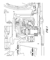
- FIG. 1 is a partial schematic diagram of an automatic transmission.
- FIG. 2 is a partial schematic diagram of the automatic transmission.
- FIG. 3 is a front view of a ring-shaped spring.
- FIG. 4 is a side view of the ring-shaped spring.
- FIG. 5 is an illustrative view of the compressed ring-shaped spring to be compressed.
- FIG. 6 is an illustrative view of the compressed ring-shaped spring.
- FIG. 7 is a graph of the spring characteristic of the ring-shaped spring, more specifically, the relationship between the load applied from a piston to the ring-shaped spring and the amount of deformation of the ring-shaped spring (or the amount of displacement of the piston) in the direction in which the load is applied.
- FIG. 8A is a time chart showing how the position of a shift lever changes with the lapse of time.
- FIG. 8B is a time chart showing how the torque of a drive shaft changes with the lapse of time.
- FIG. 8C is a time chart showing how a command value for hydraulic pressure changes with the lapse of time.
- FIG. 8D shows the relationship between the load applied to the ring-shaped spring and the amount of deformation of the ring-shaped spring in the direction in which the load is applied.
- FIG. 8E is a time chart showing how the capacity of a clutch changes with the lapse of time.
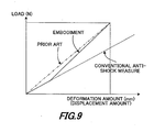
- FIG. 9 shows the spring characteristic of the ring-shaped spring as to the prior art and an embodiment of this invention, more specifically, the relationship between the load applied from the piston to the ring-shaped spring and the amount of deformation of the ring-shaped spring in the direction in which the load is applied (i.e. in the thickness direction of the ring-shaped spring).
- FIGS. 1 and 2 partially illustrate a V-belt-type continuously variable transmission to which this invention is applied.
- the V-belt-type continuously variable transmission which has an input shaft 1 to which a torque is transmitted from an engine (i.e., a power source), transmits rotation of the input shaft 1 to an output shaft (not shown) through conversion of rotational speed. A torque is outputted from the output shaft to driving wheels.
- the V-belt-type continuously variable transmission comprises a primary pulley, a secondary pulley, and a V-belt hung between the primary pulley and the secondary pulley.
- a forward-reverse changeover mechanism 3 which controls the rotational direction of rotation transmitted from the input shaft 1 to a fixed pulley 2 of the primary pulley, is installed between the input shaft 1 and the fixed pulley 2.
- the forward-reverse changeover mechanism 3 is composed of a planetary gear pair 4 and two clutches (a forward clutch 5 and a reverse clutch 6).
- the forward-reverse changeover mechanism 3 controls the rotational direction of the output shaft with respect to the rotational direction of the input shaft.
- the forward clutch 5 is engaged and the reverse clutch 6 is not engaged, rotation identical in direction to that of the input shaft 1 is transmitted to the output shaft (not shown).
- the reverse clutch 6 is engaged and the forward clutch 5 is not engaged, rotation reverse in direction to that of the input shaft 1 is transmitted to the fixed pulley 2 of the primary pulley.
- a ring gear 4r of the planetary gear pair 4 is coupled to the inside of a cylindrical outer wall 7a of a forward clutch drum 7, which is formed to be coaxial with the input shaft 1 by means of spline.
- An inner wall 7b of the forward clutch drum 7 is also formed to be cylindrical and coaxial with the input shaft 1.
- the inner wall 7b is spline-fitted to the input shaft 1.
- a driven plate 5a (axially displaceable member) of the forward clutch 5 is spline-coupled to the inside of the outer wall 7a of the forward clutch drum 7.
- a drive plate 5b (axially fixed member) capable of engaging with the driven plate 5a is fixed to a hub 15 coupled to a sun gear 4s of the planetary gear pair 4.
- the driven plate 5a and the drive plate 5b are structured by being laminated in a direction parallel to the input shaft 1.
- the forward clutch 5 is a multiple disc clutch.
- the sun gear 4s is connected to the fixed pulley 2.
- a pinion shaft 4ps supporting a pinion 4p of the planetary gear pair 4 is fixed to a carrier 4c, which is fixed to a case 8 of the automatic transmission via the reverse clutch 6.
- the reverse clutch 6 is also a multiple disc clutch.
- the forward clutch drum 7 comprises the outer wall 7a, the inner wall 7b, and a lateral wall 7c connecting them at their ends.
- a piston 9 is installed in the forward clutch drum 7.
- the piston 9 presses the forward clutch 5 (the driven plate 5a in particular) parallel to the input shaft via a ring-shaped spring 20.
- the ring-shaped spring 20 may be a belleville spring or a dished spring.
- the piston 9 moves in the direction of the input shaft due to a hydraulic pressure in an oil chamber 10 formed between the piston 9 and the lateral wall 7c of the forward clutch drum 7.
- the piston 9 presses the forward clutch 5 and generates a frictional force between the driven plate 5a and the drive plate 5b. Owing to engagement of the forward clutch 5, the engine power transmitted to the input shaft 1 is transmitted to the sun gear 4s. Oil is supplied to the oil chamber 10 from an oil passage 1a formed in the input shaft 1.
- the ring-shaped spring 20 is installed between the driven plate 5a and the piston 9.
- the ring-shaped spring 20 mitigates a shock caused by contact of the piston 9 with the driven plate 5a, and smoothens engagement of the driven plate 5a with the drive plate 5b.
- the detailed shape of this ring-shaped spring 20 will be described later.
- a spring 12 pressing the forward clutch drum 7 in the direction of the input shaft is installed between the hub 11 and the forward clutch drum 7.
- the spring 12 urges the piston 9 away from the forward clutch 5.
- a piston 13, which presses the reverse clutch 6 and generates a frictional force between the driven and drive plates 6a and 6b of the reverse clutch 6, is installed in the case 8.
- the supply of oil to an oil chamber 14 between the case 8 and the piston 13 causes the piston 13 to press the reverse clutch 6 and engages it.
- a spring (not shown) is provided to disengage the reverse clutch 6.
- FIGS. 3 to 7 illustrate the detailed shape and characteristic of the ring-shaped spring 20 of this invention.
- the ring-shaped spring 20 shown in FIGS. 3 to 5 is an annular ring made of a corrugated steel plate with a certain thickness.
- the thickness of the steel plate is a few millimeters (e.g. 2.0 mm).
- the ring-shaped spring 20 is corrugated with a series of projections (or threads) and depressions (or grooves) extending in the thickness direction.
- the corrugated ring-shaped spring 20 has two types of projection portion different in height, that is, a first contact portion 21 and a second contact portion 22 shorter in height than the first contact portion 21, and depression portions 23 formed to be flush with one another.
- the depression portions 23 are in contact with the driven plate 5a.
- the piston 9 presses the first contact portion 21 of the ring-shaped spring 20 toward the driven plate and deforms the ring-shaped spring 20.
- the ring-shaped spring 20 exhibits a first spring constant k1 of the smaller value as shown in FIG. 7.
- the piston 9 further presses the ring-shaped spring 20 toward the driven plate.
- the spring constant k of the ring-shaped spring 20 changes to a second spring constant k2 which is greater than the first spring constant k1.
- the ring-shaped spring 20 has a small spring constant when the amount of deformation of the ring-shaped spring in the thickness direction (or the amount of displacement of the piston) is below a predetermined value and a large spring constant when the amount of deformation of the ring-shaped spring in the thickness direction (or the amount of displacement of the piston) is equal to or above the predetermined value.
- the predetermined value for the amount of deformation may be close to the difference in height between two types of projection portion.
- the spring constant k of the ring-shaped spring 20 switches from the first spring constant k1 of the smaller value to the second spring constant k2 of the greater value as soon as the piston 9 comes into contact with the second contact portion 22.
- the ring-shaped spring 20 has a corrugated steel plate with a certain thickness as described above.
- the corrugated steel plate has two types of projection portion different in height.
- the more elevated projection portion (or tall projection portion) is the first contact portion 21, and the less elevated projection portion (or short projection portion) is the second contact portion 22.
- the height of projection portions may be of the same order as the thickness of the steel plate. For example, the height of the more elevated projection portion is 3 millimeters and the height of the less elevated projection portion is 2 millimeters.
- the pressure applied to the first contact portion is high.
- the amount of deformation of the first contact portion 21 is great.
- the spring constant of the ring-shaped spring 20 is small when the piston 9 is in contact only with the first contact portion 21.
- the small spring constant causes only a small force to act on the driven plate 5a and thus allows only a small torque to be transmitted by the forward clutch 5. Consequently, a shock caused upon engaging the forward clutch 5 is reduced.
- the corrugated ring-shaped spring is used in this embodiment to obtain two different spring constants, that is, a great spring constant and a small spring constant, this is not obligatory.
- a coil spring may be used instead to achieve variable spring characteristics.
- the first contact portion 21 and the second contact portion 22 are alternately formed in the ring-shaped spring 20 of this embodiment, this is not obligatory. It goes without saying that the numbers and heights of the first and second contact portions 21 and 22 and the material and thickness of the ring-shaped spring are adjusted to gain a desired spring characteristic.
- the spring constant of the ring-shaped spring 20 is switched from the spring constant k1 of the smaller value to the spring constant k2 of the greater value after the piston 9 has come into contact with the second contact portion 22 of the ring-shaped spring 20, the time consumed prior to complete engagement of the forward clutch 5 is reduced.
- the effect of the ring-shaped spring 20 will be described.
- the characteristic obtained when the ring-shaped spring 20 of this embodiment is used is indicated by a solid line.
- the characteristic of the prior art is indicated by an alternate long and short dash line, and the characteristic obtained when a ring-shaped spring with a conventional anti-shock measure is used is indicated by a broken line.
- the following description will focus on an example in which a changeover between the forward and reverse shift ranges is made in the order of R ⁇ N ⁇ D.
- the ring-shaped spring has only the spring constant k1 of the smaller value.
- the shift lever is switched from N to D at a time t1, and a command value as a command to raise the hydraulic pressure in the oil chamber 10 is outputted from a controller (not shown).
- the capacity of the clutch i.e., the torque that can be transmitted
- a fluctuation in the drive shaft torque, that is, a shock is caused at this moment, and the shock reaches its peak at a time t3.
- the ring-shaped spring 20 has the first spring constant k1 of the smaller value from the time t2 to the time t3, the peak of the shock in this invention is lower than that in the prior art. This is because the small spring constant serves to suppress the application of a load from the piston 9 to the forward clutch 5 and reduce the torque transmitted to the drive shaft.
- the spring constant of the ring-shaped spring 20 switches to the second spring constant k2 of the greater value.
- a required clutch capacity is ensured at a time t5.
- a time t7 at which a required clutch capacity is reached with the conventional anti-shock measure can be advanced to a time t6 which is equivalent to that of the prior art.
- FIG. 9 shows a comparison between the spring characteristic of the ring-shaped spring of the prior art and the spring characteristic of the ring-shaped spring 20 of this embodiment.
- the spring constant of the ring-shaped spring of this embodiment is smaller than that of the ring-shaped spring of the prior art, and substantially equal to that of the ring-shaped spring with the conventional anti-shock measure.
- the spring constant of the ring-shaped spring of this embodiment is set greater than that of the ring-shaped spring of the prior art.
- the spring constant is switches in accordance with the amount of deformation of the ring-shaped spring 20 in the thickness direction or the amount of the displacement of the piston 9. Because the spring constant k1 of the ring-shaped spring 20 is small before the piston 9 comes into contact with the second contact portion 22, a shock caused upon changing over from one shift range to another (e.g., a shock caused at the time t3 in FIG. 6) can be suppressed.
- the capacity of the clutch can be swiftly enhanced.
- the time lag from the time (t1) when the shift lever is switched from N to D to the time when the clutch capacity required for engagement of the forward clutch 5 is secured can be held substantially equal to that of the prior art.
- the ring-shaped spring 20 is installed between the piston 9 and the driven plate 5a of the forward clutch 5 in the above embodiment, a shock caused during a changeover between the forward and reverse shift ranges (especially during a changeover in the order of D ⁇ N ⁇ R) can be reduced by installing the ring-shaped spring between the driven plate 6a of the reverse clutch 6 and the piston 13.
- the ring-shaped spring 20 may be installed between the piston 9 and the driven plate 5a of the forward clutch 5 and/or between the driven plate 6a of the reverse clutch 6 and the piston 13.
- the piston 9 presses the first contact portion 21 and/or the second contact portion 22 while the depression portions 23 are in contact with the driven plate 5a.
- the first contact portion 21 and/or the second contact portion 22 presses the driven plate 5a of the clutch while the depression portions 23 may be in contact with the piston 9 (see FIG. 5). That is, the depression portions 23 may be provided on the piston side, and the first contact portion 21 and the second contact portion 22 may be provided on the clutch side.
Landscapes
- Engineering & Computer Science (AREA)
- General Engineering & Computer Science (AREA)
- Mechanical Engineering (AREA)
- Hydraulic Clutches, Magnetic Clutches, Fluid Clutches, And Fluid Joints (AREA)
- Mechanical Operated Clutches (AREA)
Abstract
A forward-reverse changeover mechanism for an automatic
transmission is disclosed. The automatic transmission has an input shaft (1)
to which a torque is inputted and an output shaft from which a torque is
outputted. The forward-reverse changeover mechanism is installed between
the input shaft and the output shaft and controls a rotational direction of
the output shaft with respect to a rotational direction of the input shaft. The
forward-reverse changeover mechanism includes a clutch (5/6) that is
engaged when rotation identical or reverse in direction to rotation of the
input shaft (1) is transmitted to the output shaft; a piston (9/13) that
controls engagement/disengagement of the clutch; and a ring-shaped spring
(20) that is interposed between the clutch (5/6) and the piston (9/13) and
receives a load from the piston (9/13), wherein the load causes a
deformation of the ring-shaped spring (20). A spring constant (k) of the
ring-shaped spring (20) switches according to an amount of the deformation
of the ring-shaped spring (20).
Description
This invention relates to an automatic transmission and a
forward-reverse changeover mechanism for the automatic
transmission.
A forward-reverse changeover mechanism disclosed in JP
09-32918 A published by the Japanese Patent Office in 1997
provides a ring-shaped spring (which is a belleville spring) between a
clutch and a piston for controlling engagement of the clutch.
However, since the ring-shaped spring of the prior art has an
invariable spring constant, a shock caused upon a reversal of a
direction of torque transmission in shifting a position of a shift lever
or an operational range of an automatic transmission in an order of a
reverse range (R) → a neutral range (N) → a drive range (D) or in an
order of D→N→R is increased. When this shock is suppressed, a
time period consumed prior to an attainment of a required clutch
capacity (i.e., a required torque that is transmitted by the clutch) is
prolonged.
It is an object of this invention to provide a forward-reverse
changeover mechanism for an automatic transmission capable of
reducing a shock caused upon reversing a direction of torque
transmission while cutting down on a time period consumed prior to
an attainment of a required clutch capacity.
In order to achieve the above object, this invention provides a
forward-reverse changeover mechanism for an automatic
transmission. The automatic transmission has an input shaft to
which a torque is inputted and an output shaft from which a torque
is outputted. The forward-reverse changeover mechanism is installed
between the input shaft and the output shaft and controls a
rotational direction of the output shaft with respect to a rotational
direction of the input shaft. The forward-reverse changeover
mechanism includes a clutch that is engaged when rotation identical
or reverse in direction to rotation of the input shaft is transmitted to
the output shaft; a piston that controls engagement/ disengagement
of the clutch; and a ring-shaped spring that is interposed between
the clutch and the piston and receives a load from the piston,
wherein the load causes a deformation of the ring-shaped spring. A
spring constant of the ring-shaped spring switches according to an
amount of the deformation of the ring-shaped spring.
Preferably, the ring-shaped spring has a small spring constant
when the amount of deformation of the ring-shaped spring is below a
predetermined value and a large spring constant when the amount of
deformation of the ring-shaped spring is equal to or above the
predetermined value.
Preferably, the ring-shaped spring comprises a tall projection
portion and a short projection portion which are different in height,
and the spring constant of the ring-shaped spring switches when the
piston or the clutch comes into contact with both of the tall
projection portion and the short projection portion.
The details as well as other features and advantages of this
invention are set forth in the remainder of the specification and are
shown in the accompanying drawings.
FIG. 1 is a partial schematic diagram of an automatic
transmission.
FIG. 2 is a partial schematic diagram of the automatic
transmission.
FIG. 3 is a front view of a ring-shaped spring.
FIG. 4 is a side view of the ring-shaped spring.
FIG. 5 is an illustrative view of the compressed ring-shaped spring
to be compressed.
FIG. 6 is an illustrative view of the compressed ring-shaped
spring.
FIG. 7 is a graph of the spring characteristic of the ring-shaped
spring, more specifically, the relationship between the load applied
from a piston to the ring-shaped spring and the amount of
deformation of the ring-shaped spring (or the amount of
displacement of the piston) in the direction in which the load is
applied.
FIG. 8A is a time chart showing how the position of a shift lever
changes with the lapse of time. FIG. 8B is a time chart showing how
the torque of a drive shaft changes with the lapse of time. FIG. 8C is
a time chart showing how a command value for hydraulic pressure
changes with the lapse of time. FIG. 8D shows the relationship
between the load applied to the ring-shaped spring and the amount
of deformation of the ring-shaped spring in the direction in which the
load is applied. FIG. 8E is a time chart showing how the capacity of
a clutch changes with the lapse of time.
FIG. 9 shows the spring characteristic of the ring-shaped spring as
to the prior art and an embodiment of this invention, more
specifically, the relationship between the load applied from the piston
to the ring-shaped spring and the amount of deformation of the
ring-shaped spring in the direction in which the load is applied (i.e.
in the thickness direction of the ring-shaped spring).
FIGS. 1 and 2 partially illustrate a V-belt-type continuously
variable transmission to which this invention is applied.
The V-belt-type continuously variable transmission, which has an
input shaft 1 to which a torque is transmitted from an engine (i.e., a
power source), transmits rotation of the input shaft 1 to an output
shaft (not shown) through conversion of rotational speed. A torque
is outputted from the output shaft to driving wheels. The
V-belt-type continuously variable transmission comprises a primary
pulley, a secondary pulley, and a V-belt hung between the primary
pulley and the secondary pulley. A forward-reverse changeover
mechanism 3, which controls the rotational direction of rotation
transmitted from the input shaft 1 to a fixed pulley 2 of the primary
pulley, is installed between the input shaft 1 and the fixed pulley 2.
Although the automatic transmission of this invention is described as
a V-belt-type continuously variable transmission in this embodiment,
this invention is not limited to this type of automatic transmission.
Referring to FIG. 2, the forward-reverse changeover mechanism 3
is composed of a planetary gear pair 4 and two clutches (a forward
clutch 5 and a reverse clutch 6). The forward-reverse changeover
mechanism 3 controls the rotational direction of the output shaft
with respect to the rotational direction of the input shaft. When the
forward clutch 5 is engaged and the reverse clutch 6 is not engaged,
rotation identical in direction to that of the input shaft 1 is
transmitted to the output shaft (not shown). On the other hand,
when the reverse clutch 6 is engaged and the forward clutch 5 is not
engaged, rotation reverse in direction to that of the input shaft 1 is
transmitted to the fixed pulley 2 of the primary pulley.
The forward-reverse changeover mechanism 3 will now be
described in detail. A ring gear 4r of the planetary gear pair 4 is
coupled to the inside of a cylindrical outer wall 7a of a forward clutch
drum 7, which is formed to be coaxial with the input shaft 1 by
means of spline. An inner wall 7b of the forward clutch drum 7 is
also formed to be cylindrical and coaxial with the input shaft 1. The
inner wall 7b is spline-fitted to the input shaft 1.
A driven plate 5a (axially displaceable member) of the forward
clutch 5 is spline-coupled to the inside of the outer wall 7a of the
forward clutch drum 7. On the other hand, a drive plate 5b (axially
fixed member) capable of engaging with the driven plate 5a is fixed to
a hub 15 coupled to a sun gear 4s of the planetary gear pair 4. The
driven plate 5a and the drive plate 5b are structured by being
laminated in a direction parallel to the input shaft 1. In other words,
the forward clutch 5 is a multiple disc clutch. The sun gear 4s is
connected to the fixed pulley 2.
A pinion shaft 4ps supporting a pinion 4p of the planetary gear
pair 4 is fixed to a carrier 4c, which is fixed to a case 8 of the
automatic transmission via the reverse clutch 6. As is the case with
the forward clutch 5, the reverse clutch 6 is also a multiple disc
clutch.
The forward clutch drum 7 comprises the outer wall 7a, the inner
wall 7b, and a lateral wall 7c connecting them at their ends. A
piston 9 is installed in the forward clutch drum 7. The piston 9
presses the forward clutch 5 (the driven plate 5a in particular)
parallel to the input shaft via a ring-shaped spring 20. The
ring-shaped spring 20 may be a belleville spring or a dished spring.
The piston 9 moves in the direction of the input shaft due to a
hydraulic pressure in an oil chamber 10 formed between the piston 9
and the lateral wall 7c of the forward clutch drum 7. The piston 9
presses the forward clutch 5 and generates a frictional force between
the driven plate 5a and the drive plate 5b. Owing to engagement of
the forward clutch 5, the engine power transmitted to the input shaft
1 is transmitted to the sun gear 4s. Oil is supplied to the oil
chamber 10 from an oil passage 1a formed in the input shaft 1.
The ring-shaped spring 20 is installed between the driven plate 5a
and the piston 9. The ring-shaped spring 20 mitigates a shock
caused by contact of the piston 9 with the driven plate 5a, and
smoothens engagement of the driven plate 5a with the drive plate 5b.
The detailed shape of this ring-shaped spring 20 will be described
later.
A hub 11, which is fixed to the forward clutch drum 7 and slides
along the inner surface of the piston 9 via a seal, is installed. A
spring 12 pressing the forward clutch drum 7 in the direction of the
input shaft is installed between the hub 11 and the forward clutch
drum 7. The spring 12 urges the piston 9 away from the forward
clutch 5. When the forward clutch 5 is disengaged, no oil is
supplied to the oil chamber 10, the hydraulic pressure in the oil
chamber 10 decreases, and the spring 12 causes the piston 9 to
move away from the forward clutch 5 so as to disengage the forward
clutch 5. This is because the urging force of the spring 12 exceeds a
force originating from the hydraulic pressure in the oil chamber 10
and causing the piston 9 to move toward the forward clutch 5.
A piston 13, which presses the reverse clutch 6 and generates a
frictional force between the driven and drive plates 6a and 6b of the
reverse clutch 6, is installed in the case 8. The supply of oil to an oil
chamber 14 between the case 8 and the piston 13 causes the piston
13 to press the reverse clutch 6 and engages it. A spring (not
shown) is provided to disengage the reverse clutch 6.
The structure of the ring-shaped spring 20 used in the automatic
transmission structured as described above will now be described.
FIGS. 3 to 7 illustrate the detailed shape and characteristic of the
ring-shaped spring 20 of this invention. The ring-shaped spring 20
shown in FIGS. 3 to 5 is an annular ring made of a corrugated steel
plate with a certain thickness. For example, the thickness of the steel
plate is a few millimeters (e.g. 2.0 mm). In side view, the
ring-shaped spring 20 is corrugated with a series of projections (or
threads) and depressions (or grooves) extending in the thickness
direction. The corrugated ring-shaped spring 20 has two types of
projection portion different in height, that is, a first contact portion
21 and a second contact portion 22 shorter in height than the first
contact portion 21, and depression portions 23 formed to be flush
with one another. The depression portions 23 are in contact with the
driven plate 5a.
As described above, since the ring-shaped spring 20 is installed
between the driven plate 5a and the piston 9, movement of the piston
9 resulting from a hydraulic pressure deforms the ring-shaped spring
20 in the direction of the input shaft and allows it to show a
predetermined spring characteristic.
Referring to FIG. 5, the piston 9 presses the first contact portion
21 of the ring-shaped spring 20 toward the driven plate and deforms
the ring-shaped spring 20. At first, the ring-shaped spring 20
exhibits a first spring constant k1 of the smaller value as shown in
FIG. 7. Then, as shown in FIG. 6, the piston 9 further presses the
ring-shaped spring 20 toward the driven plate. Thereafter, when the
piston 9 comes into contact with the second contact portion 22, the
spring constant k of the ring-shaped spring 20 changes to a second
spring constant k2 which is greater than the first spring constant k1.
The ring-shaped spring 20 has a small spring constant when the
amount of deformation of the ring-shaped spring in the thickness
direction (or the amount of displacement of the piston) is below a
predetermined value and a large spring constant when the amount of
deformation of the ring-shaped spring in the thickness direction (or
the amount of displacement of the piston) is equal to or above the
predetermined value. The predetermined value for the amount of
deformation may be close to the difference in height between two
types of projection portion. Because the ring-shaped spring 20 is
thus provided with the two types of contact portions 21 and 22
different in height, the spring constant k of the ring-shaped spring 20
switches from the first spring constant k1 of the smaller value to the
second spring constant k2 of the greater value as soon as the piston
9 comes into contact with the second contact portion 22.
Namely, the ring-shaped spring 20 has a corrugated steel plate
with a certain thickness as described above. The corrugated steel
plate has two types of projection portion different in height. The
more elevated projection portion (or tall projection portion) is the first
contact portion 21, and the less elevated projection portion (or short
projection portion) is the second contact portion 22. The height of
projection portions may be of the same order as the thickness of the
steel plate. For example, the height of the more elevated projection
portion is 3 millimeters and the height of the less elevated projection
portion is 2 millimeters. When the piston 9 moves, it first comes into
contact with the taller projection portion, that is, the first contact
portion 21. At this moment, the piston 9 is in contact only with the
first contact portion and not with a large area. Therefore, the
pressure applied to the first contact portion is high. Thus, the
amount of deformation of the first contact portion 21 is great. In
other words, the spring constant of the ring-shaped spring 20 is
small when the piston 9 is in contact only with the first contact
portion 21. Given that the amount of deformation of the
ring-shaped spring 20 (or the amount of displacement of the piston)
is constant, the small spring constant causes only a small force to
act on the driven plate 5a and thus allows only a small torque to be
transmitted by the forward clutch 5. Consequently, a shock caused
upon engaging the forward clutch 5 is reduced.
When the piston 9 further moves and comes into contact with the
second contact portion 22, it is actually in contact with the first and
second contact portions 21 and 22 of the ring-shaped spring 20.
Therefore, the pressure applied to each of the contact portions is low.
Thus, the amount of deformation of each of the contact portions is
small. In other words, the spring constant of the ring-shaped spring
20 is great when the piston 9 is in contact with the first and second
contact portions. Hence, given that the amount of deformation of
the ring-shaped spring 20 is constant, an increase in spring constant
leads to an increase in the force acting on the driven plate 5a. Thus,
the torque that can be transmitted by the forward clutch 5 (i.e., the
capacity of the forward clutch 5) is rapidly enhanced when the piston
9 is in contact with the first and second contact portions.
Although the corrugated ring-shaped spring is used in this
embodiment to obtain two different spring constants, that is, a great
spring constant and a small spring constant, this is not obligatory.
For instance, a coil spring may be used instead to achieve variable
spring characteristics. Further, although the first contact portion
21 and the second contact portion 22 are alternately formed in the
ring-shaped spring 20 of this embodiment, this is not obligatory. It
goes without saying that the numbers and heights of the first and
second contact portions 21 and 22 and the material and thickness of
the ring-shaped spring are adjusted to gain a desired spring
characteristic.
At the early stage of engagement of the driven plate 5a of the
forward clutch 5 with the drive plate 5b, the load from the piston 9 is
transmitted to the driven plate 5a via the ring-shaped spring 20 with
the smaller spring constant k1. Therefore, only a small torque can
be transmitted. Thus, when a changeover between forward and
reverse ranges is made with a reversal of the direction of torque
transmission, that is, when the operational range of the transmission
is shifted in the order of R→N→D or D→N→R, a shock is reduced.
Moreover, since the spring constant of the ring-shaped spring 20 is
switched from the spring constant k1 of the smaller value to the
spring constant k2 of the greater value after the piston 9 has come
into contact with the second contact portion 22 of the ring-shaped
spring 20, the time consumed prior to complete engagement of the
forward clutch 5 is reduced.
Referring to FIG. 8, the effect of the ring-shaped spring 20 will be
described. In FIG. 8, the characteristic obtained when the
ring-shaped spring 20 of this embodiment is used is indicated by a
solid line. The characteristic of the prior art is indicated by an
alternate long and short dash line, and the characteristic obtained
when a ring-shaped spring with a conventional anti-shock measure
is used is indicated by a broken line. The following description will
focus on an example in which a changeover between the forward and
reverse shift ranges is made in the order of R→N→D. With the
conventional anti-shock measure, the ring-shaped spring has only
the spring constant k1 of the smaller value.
Referring to FIG. 8A, the shift lever is switched from N to D at a
time t1, and a command value as a command to raise the hydraulic
pressure in the oil chamber 10 is outputted from a controller (not
shown). Referring to FIG. 8E, the capacity of the clutch (i.e., the
torque that can be transmitted) increases with a delay after the
outputting of the command value, namely, at a time t2. Referring to
FIG. 8B, a fluctuation in the drive shaft torque, that is, a shock is
caused at this moment, and the shock reaches its peak at a time t3.
However, since the ring-shaped spring 20 has the first spring
constant k1 of the smaller value from the time t2 to the time t3, the
peak of the shock in this invention is lower than that in the prior art.
This is because the small spring constant serves to suppress the
application of a load from the piston 9 to the forward clutch 5 and
reduce the torque transmitted to the drive shaft.
After the time t3 when the shock reaches its peak, the spring
constant of the ring-shaped spring 20 switches to the second spring
constant k2 of the greater value. As in the case of the prior art, a
required clutch capacity is ensured at a time t5. Further, since the
spring constant of the ring-shaped spring 20 switches to the second
spring constant k2 after the shock has passed its peak, a time t7 at
which a required clutch capacity is reached with the conventional
anti-shock measure can be advanced to a time t6 which is equivalent
to that of the prior art.
FIG. 9 shows a comparison between the spring characteristic of
the ring-shaped spring of the prior art and the spring characteristic
of the ring-shaped spring 20 of this embodiment. As is apparent
from FIG. 9, before the piston 9 comes into contact with the second
contact portion 22, the spring constant of the ring-shaped spring of
this embodiment is smaller than that of the ring-shaped spring of the
prior art, and substantially equal to that of the ring-shaped spring
with the conventional anti-shock measure. After the piston 9 has
come into contact with the second contact portion 22, the spring
constant of the ring-shaped spring of this embodiment is set greater
than that of the ring-shaped spring of the prior art.
Therefore, when the ring-shaped spring 20 having the two types of
projection portion different in height (the first and second contact
portions 21 and 22) as in the case of this embodiment is used, the
spring constant is switches in accordance with the amount of
deformation of the ring-shaped spring 20 in the thickness direction
or the amount of the displacement of the piston 9. Because the
spring constant k1 of the ring-shaped spring 20 is small before the
piston 9 comes into contact with the second contact portion 22, a
shock caused upon changing over from one shift range to another
(e.g., a shock caused at the time t3 in FIG. 6) can be suppressed.
On the other hand, because the spring constant of the ring-shaped
spring 20 is switched to the spring constant k2 of the greater value
after the piston 9 has come into contact with the second contact
portion 22, the capacity of the clutch can be swiftly enhanced. Thus,
the time lag from the time (t1) when the shift lever is switched from N
to D to the time when the clutch capacity required for engagement of
the forward clutch 5 is secured, can be held substantially equal to
that of the prior art.
By thus changing the spring characteristic of the ring-shaped
spring in two stages, a shock caused upon changing over from one
shift range to another is reduced, and the time consumed prior to the
securement of a required clutch capacity is prevented from
increasing.
Although the invention has been described above by reference to a
certain embodiment of the invention, the invention is not limited to
the embodiments described above.
Although the ring-shaped spring 20 is installed between the piston
9 and the driven plate 5a of the forward clutch 5 in the above
embodiment, a shock caused during a changeover between the
forward and reverse shift ranges (especially during a changeover in
the order of D→N→R) can be reduced by installing the ring-shaped
spring between the driven plate 6a of the reverse clutch 6 and the
piston 13. In other words, the ring-shaped spring 20 may be installed
between the piston 9 and the driven plate 5a of the forward clutch 5
and/or between the driven plate 6a of the reverse clutch 6 and the
piston 13.
In the above embodiment, the piston 9 presses the first contact
portion 21 and/or the second contact portion 22 while the
depression portions 23 are in contact with the driven plate 5a.
However, the first contact portion 21 and/or the second contact
portion 22 presses the driven plate 5a of the clutch while the
depression portions 23 may be in contact with the piston 9 (see FIG.
5). That is, the depression portions 23 may be provided on the piston
side, and the first contact portion 21 and the second contact portion
22 may be provided on the clutch side.
Modifications and variations of the embodiments described above
will occur to those skilled in the art, in light of the above teachings.
The scope of the invention is defined with reference to the following
claims.
The entire contents of Japanese Patent Application P2004-101172
(filed March 30, 2004) are incorporated herein by reference.
Claims (10)
- A forward-reverse changeover mechanism for an automatic transmission, the automatic transmission comprising an input shaft (1) to which a torque is inputted and an output shaft from which a torque is outputted, the forward-reverse changeover mechanism being installed between the input shaft and the output shaft and controlling a rotational direction of the output shaft with respect to a rotational direction of the input shaft, the forward-reverse changeover mechanism comprising:wherein a spring constant (k) of the ring-shaped spring (20) switches according to an amount of the deformation of the ring-shaped spring (20).a clutch (5/6) that is engaged when rotation identical or reverse in direction to rotation of the input shaft (1) is transmitted to the output shaft;a piston (9/13) that controls engagement/disengagement of the clutch; anda ring-shaped spring (20) that is interposed between the clutch (5/6) and the piston (9/13) and receives a load from the piston (9/13), wherein the load causes a deformation of the ring-shaped spring (20);
- The forward-reverse changeover mechanism as defined in claim 1, wherein the ring-shaped spring (20) has a small spring constant (k1) when the amount of deformation of the ring-shaped spring (20) is below a predetermined value and a large spring constant (k2) when the amount of deformation of the ring-shaped spring (20) is equal to or above the predetermined value.
- The forward-reverse changeover mechanism as defined in claim 1,
wherein the ring-shaped spring (20) comprises a tall projection portion (21) and a short projection portion (22) which are different in height, and
wherein the spring constant (k) of the ring-shaped spring (20) switches when the piston (9/13) or the clutch (5/6) comes into contact with both of the tall projection portion (21) and the short projection portion (22). - The forward-reverse changeover mechanism as defined in claim 1, wherein the ring-shaped spring (20) comprises a tall projection portion (21) and a short projection portion (22), wherein the tall and short projection portions (21,22) are different in height and can come into contact with the piston (9/13) or the clutch (5/6) during operation thereof.
- The forward-reverse changeover mechanism as defined in claim 4,
wherein the ring-shaped spring (20) is corrugated. - The forward-reverse changeover mechanism as defined in claim 4, wherein the ring-shaped spring (20) has a small spring constant (k1) when the piston (9/13) or the clutch (5/6) is in contact with only the tall projection portion (21) and a large spring constant (k2) when the piston (9/13) or the clutch (5/6) is in contact with both the tall and short projection portions (21,22).
- The forward-reverse changeover mechanism as defined in claim 1, wherein the spring constant (k) of the ring-shaped spring (20) switches according to an amount of the displacement of the piston (9/13).
- The forward-reverse changeover mechanism as defined in claim 7, wherein the ring-shaped spring (20) has a small spring constant (k1) when the amount of displacement of the piston (9/13) is below a predetermined value and a large spring constant (k2) when the amount of displacement of the piston (9 / 13) is equal to or above the predetermined value.
- The forward-reverse changeover mechanism as defined in claim 8,
wherein the ring-shaped spring (20) comprises a tall projection portion (21) and a short projection portion (22) which are different in height, and
wherein the piston or the clutch comes into contact with the tall projection portion and the short projection portion when the amount of displacement of the piston (9/13) becomes the predetermined value. - An automatic transmission comprising the forward-reverse changeover mechanism according to claim 1.
Applications Claiming Priority (2)
| Application Number | Priority Date | Filing Date | Title |
|---|---|---|---|
| JP2004101172 | 2004-03-30 | ||
| JP2004101172A JP2005282811A (en) | 2004-03-30 | 2004-03-30 | Automatic transmission |
Publications (1)
| Publication Number | Publication Date |
|---|---|
| EP1582767A2 true EP1582767A2 (en) | 2005-10-05 |
Family
ID=34880004
Family Applications (1)
| Application Number | Title | Priority Date | Filing Date |
|---|---|---|---|
| EP05005765A Withdrawn EP1582767A2 (en) | 2004-03-30 | 2005-03-16 | Forward-reverse changeover mechanism for an automatic transmission |
Country Status (3)
| Country | Link |
|---|---|
| US (1) | US20050217964A1 (en) |
| EP (1) | EP1582767A2 (en) |
| JP (1) | JP2005282811A (en) |
Cited By (2)
| Publication number | Priority date | Publication date | Assignee | Title |
|---|---|---|---|---|
| EP2143967A4 (en) * | 2007-04-03 | 2012-01-18 | Nhk Spring Co Ltd | METHOD FOR PRODUCING A CONICAL DISK SPRING, AND CLUTCH DEVICE |
| CN102788151A (en) * | 2011-05-19 | 2012-11-21 | 现代自动车株式会社 | Apparatus for reducing transmission shock in automatic transmission |
Families Citing this family (8)
| Publication number | Priority date | Publication date | Assignee | Title |
|---|---|---|---|---|
| JP4545489B2 (en) * | 2004-06-01 | 2010-09-15 | アイシン・エィ・ダブリュ株式会社 | Cushion plate |
| DE102004040886A1 (en) * | 2004-08-24 | 2006-03-02 | Volkswagen Ag | Operating device for a motor vehicle |
| JP5101028B2 (en) * | 2006-03-24 | 2012-12-19 | 日本発條株式会社 | Belleville spring manufacturing method and clutch device |
| DE102006047295A1 (en) * | 2006-10-06 | 2008-04-10 | Zf Friedrichshafen Ag | Coupling arrangement for a vehicle |
| CN103953697B (en) * | 2014-05-26 | 2016-08-17 | 雷沃重工股份有限公司 | A kind of tractor dynamic power high and low shift structure |
| JP2016196896A (en) * | 2015-04-02 | 2016-11-24 | 株式会社ジェイテクト | Frictional engagement device and friction plate |
| JP6945482B2 (en) | 2018-03-28 | 2021-10-06 | 株式会社小松製作所 | Friction engagement device for work vehicle and work vehicle |
| JP7061976B2 (en) * | 2019-02-01 | 2022-05-02 | 株式会社アイシン | Friction engagement device |
Citations (2)
| Publication number | Priority date | Publication date | Assignee | Title |
|---|---|---|---|---|
| JPH0932918A (en) | 1995-07-17 | 1997-02-07 | Jatco Corp | Friction engagement device for automatic transmission and automatic transmission |
| JP2004101172A (en) | 2002-08-23 | 2004-04-02 | Sanyo Electric Co Ltd | Air conditioner |
Family Cites Families (10)
| Publication number | Priority date | Publication date | Assignee | Title |
|---|---|---|---|---|
| US3285379A (en) * | 1964-10-21 | 1966-11-15 | Ford Motor Co | Fluid pressure clutch with spring cushion |
| US3362481A (en) * | 1966-01-13 | 1968-01-09 | Twin Disc Inc | Hydraulically operated friction clutch having a dump valve |
| US4261455A (en) * | 1978-12-26 | 1981-04-14 | Allis-Chalmers Corporation | Centrifugal pressure relief valve for a hydraulic clutch |
| JPS6086627U (en) * | 1983-11-18 | 1985-06-14 | 株式会社大金製作所 | hydraulic clutch |
| JP3507094B2 (en) * | 1993-01-27 | 2004-03-15 | 愛知機械工業株式会社 | Transmission forward / backward switching device |
| US5906255A (en) * | 1997-06-18 | 1999-05-25 | Deltrans, Inc. | Automatic transmission clutch drum assembly with waved ring spring |
| US6227340B1 (en) * | 1999-08-24 | 2001-05-08 | Borgwarner Inc. | Automatic transmission with dual gain multi-disk friction device |
| JP3926109B2 (en) * | 2001-02-19 | 2007-06-06 | 株式会社エクセディ | Forward / reverse device for continuously variable transmission |
| JP2003035325A (en) * | 2001-07-23 | 2003-02-07 | Nsk Warner Kk | Wet type multiple disc clutch |
| DE10321800A1 (en) * | 2003-05-14 | 2004-12-09 | Muhr Und Bender Kg | Corrugated fields with gradually progressive spring characteristic |
-
2004
- 2004-03-30 JP JP2004101172A patent/JP2005282811A/en active Pending
-
2005
- 2005-03-16 EP EP05005765A patent/EP1582767A2/en not_active Withdrawn
- 2005-03-21 US US11/085,003 patent/US20050217964A1/en not_active Abandoned
Patent Citations (2)
| Publication number | Priority date | Publication date | Assignee | Title |
|---|---|---|---|---|
| JPH0932918A (en) | 1995-07-17 | 1997-02-07 | Jatco Corp | Friction engagement device for automatic transmission and automatic transmission |
| JP2004101172A (en) | 2002-08-23 | 2004-04-02 | Sanyo Electric Co Ltd | Air conditioner |
Cited By (4)
| Publication number | Priority date | Publication date | Assignee | Title |
|---|---|---|---|---|
| EP2143967A4 (en) * | 2007-04-03 | 2012-01-18 | Nhk Spring Co Ltd | METHOD FOR PRODUCING A CONICAL DISK SPRING, AND CLUTCH DEVICE |
| US9003661B2 (en) | 2007-04-03 | 2015-04-14 | Nhk Spring Co., Ltd. | Production method for coned disc spring and clutch apparatus provided with coned disc spring |
| US9194440B2 (en) | 2007-04-03 | 2015-11-24 | Nhk Spring Co., Ltd. | Production method for coned disc spring and clutch apparatus provided with coned disc spring |
| CN102788151A (en) * | 2011-05-19 | 2012-11-21 | 现代自动车株式会社 | Apparatus for reducing transmission shock in automatic transmission |
Also Published As
| Publication number | Publication date |
|---|---|
| US20050217964A1 (en) | 2005-10-06 |
| JP2005282811A (en) | 2005-10-13 |
Similar Documents
| Publication | Publication Date | Title |
|---|---|---|
| US4623055A (en) | Hydraulic clutch | |
| KR101543038B1 (en) | Transmission | |
| US8225917B2 (en) | Fluid coupling and coupling method thereof | |
| US10247305B2 (en) | Automatic transmission | |
| US20050217964A1 (en) | Forward-reverse changeover mechanism for an automatic transmission | |
| US10473166B2 (en) | Frictional engagement element and automatic transmission | |
| US8864610B2 (en) | Belt type continuously variable transmission for vehicle | |
| US9194440B2 (en) | Production method for coned disc spring and clutch apparatus provided with coned disc spring | |
| US20010035328A1 (en) | Clutch device for an automatic transmission | |
| EP2226532A1 (en) | Control apparatus and method for automatic transmission | |
| EP2833027A1 (en) | Continuously variable transmission and hydraulic pressure control method therefor | |
| KR100577657B1 (en) | Automatic transmission | |
| US20050155826A1 (en) | Friction engaging device | |
| JP2005282807A (en) | Disc spring | |
| US20190293129A1 (en) | Frictional coupling device of vehicular power transmitting system | |
| JP2003148515A (en) | Hydraulic engagement device | |
| US20050181899A1 (en) | Continuously variable transmission | |
| US20160215879A1 (en) | Control apparatus and control method for automatic transmission | |
| JP2005344792A (en) | Cushion plate | |
| EP1258388A2 (en) | Power transmission | |
| JPH01247827A (en) | hydraulic clutch structure | |
| US3782216A (en) | Speed change control system for automatic transmission | |
| US20210254672A1 (en) | Friction engagement element control system and method of controlling friction engagement element | |
| JP4215289B2 (en) | Cushion plate | |
| JPH0126407B2 (en) |
Legal Events
| Date | Code | Title | Description |
|---|---|---|---|
| PUAI | Public reference made under article 153(3) epc to a published international application that has entered the european phase |
Free format text: ORIGINAL CODE: 0009012 |
|
| 17P | Request for examination filed |
Effective date: 20050316 |
|
| AK | Designated contracting states |
Kind code of ref document: A2 Designated state(s): AT BE BG CH CY CZ DE DK EE ES FI FR GB GR HU IE IS IT LI LT LU MC NL PL PT RO SE SI SK TR |
|
| AX | Request for extension of the european patent |
Extension state: AL BA HR LV MK YU |
|
| STAA | Information on the status of an ep patent application or granted ep patent |
Free format text: STATUS: THE APPLICATION HAS BEEN WITHDRAWN |
|
| 18W | Application withdrawn |
Effective date: 20070131 |