EP1582752A1 - Locking mechanism and open roof construction provided therewith - Google Patents
Locking mechanism and open roof construction provided therewith Download PDFInfo
- Publication number
- EP1582752A1 EP1582752A1 EP04101280A EP04101280A EP1582752A1 EP 1582752 A1 EP1582752 A1 EP 1582752A1 EP 04101280 A EP04101280 A EP 04101280A EP 04101280 A EP04101280 A EP 04101280A EP 1582752 A1 EP1582752 A1 EP 1582752A1
- Authority
- EP
- European Patent Office
- Prior art keywords
- locking
- pin
- drive
- mechanism according
- locking mechanism
- Prior art date
- Legal status (The legal status is an assumption and is not a legal conclusion. Google has not performed a legal analysis and makes no representation as to the accuracy of the status listed.)
- Granted
Links
Images



Classifications
-
- B—PERFORMING OPERATIONS; TRANSPORTING
- B60—VEHICLES IN GENERAL
- B60J—WINDOWS, WINDSCREENS, NON-FIXED ROOFS, DOORS, OR SIMILAR DEVICES FOR VEHICLES; REMOVABLE EXTERNAL PROTECTIVE COVERINGS SPECIALLY ADAPTED FOR VEHICLES
- B60J7/00—Non-fixed roofs; Roofs with movable panels, e.g. rotary sunroofs
- B60J7/185—Locking arrangements
-
- F—MECHANICAL ENGINEERING; LIGHTING; HEATING; WEAPONS; BLASTING
- F16—ENGINEERING ELEMENTS AND UNITS; GENERAL MEASURES FOR PRODUCING AND MAINTAINING EFFECTIVE FUNCTIONING OF MACHINES OR INSTALLATIONS; THERMAL INSULATION IN GENERAL
- F16B—DEVICES FOR FASTENING OR SECURING CONSTRUCTIONAL ELEMENTS OR MACHINE PARTS TOGETHER, e.g. NAILS, BOLTS, CIRCLIPS, CLAMPS, CLIPS OR WEDGES; JOINTS OR JOINTING
- F16B21/00—Means for preventing relative axial movement of a pin, spigot, shaft or the like and a member surrounding it; Stud-and-socket releasable fastenings
- F16B21/02—Releasable fastening devices locking by rotation
- F16B21/04—Releasable fastening devices locking by rotation with bayonet catch
Definitions
- the invention firstly relates to a locking mechanism for locking together two parts, comprising a first movable locking member connected to a first one of said parts and a second locking member connected to a second one of said parts, wherein the first locking member is movable between a release position in which it disengages the second locking member and a locking position in which it lockingly engages the second locking member.
- a locking mechanism for locking together two parts comprising a first movable locking member connected to a first one of said parts and a second locking member connected to a second one of said parts, wherein the first locking member is movable between a release position in which it disengages the second locking member and a locking position in which it lockingly engages the second locking member, characterized in that the first locking member comprises an elongate, substantially cylindrically shaped locking pin which can translate in its longitudinal direction and which can rotate around its longitudinal axis, wherein said locking pin is housed in a tubular guide member for defining the translational and rotational movements of the locking pin, and wherein the locking pin is operatively connected to a drive member for in combination with the guide member causing the movements of the locking pin relative to the guide member and thus relative to the second locking member.
- the locking mechanism according to the present invention does not contain any parts which are hingeably connected to each other.
- the locking pin only translates in its longitudinal direction and rotates around its longitudinal axis, thus limiting the dimensions of the locking mechanism.
- the absence of hinges makes the locking mechanisms less complicated than existing locking mechanisms, leading to an extremely reliable locking mechanism.
- the combination of translational and rotational movements of the locking pin caused by the drive member and guide member leads to the desired engagement and disengagement between the first locking member and the second locking member.
- the guide member comprises at least one guide channel with a first longitudinal section and a connecting transverse section, whereas the locking pin comprises a corresponding guide projection projecting into said guide channel.
- the locking pin As long as the guide projection of the locking pin is received in the first longitudinal section of the guide channel, the locking pin only will translate. As soon as the guide projection has reached the transverse section of the guide channel, the locking pin will rotate.
- the guide member comprises two guide channels positioned one diametrically opposite the other
- the locking pin correspondingly comprises two guide projections positioned one diametrically opposite the other
- the drive member comprises a drive pin movable in the longitudinal direction of the locking pin, with at least one drive projection that engages the locking pin. Moving the drive pin in the longitudinal direction (for example by means of a cable drive) the locking pin is correspondingly moved.
- the locking pin comprises a longitudinally extending bore for at least partially housing the drive member, the entire locking mechanism is extremely compact with small outer dimensions.
- the cooperation between the drive member and the locking pin can be optimised, when the locking pin comprises at least one spiral shaped channel into which the drive projection of the drive pin extends and wherein means are provided for preventing a rotation of the drive pin relative to the guide member.
- the drive projection of the drive member only will move in a longitudinal direction. During such a movement it will move the locking pin in that longitudinal direction too, as long as the guide projection of the locking pin is received in the longitudinal section of the guide channel of the guide member. During this stage of the movement, the drive projection of the drive member assumes a stationary position in the spiral shaped channel of the locking pin. When the guide projection of the locking pin has reached the transverse section of the guide channel, the longitudinal movement of the locking pin is stopped, and a rotational movement starts.
- the means for preventing a rotation of the drive pin relative to the guide member comprises a longitudinally extending auxiliary channel provided in the guide member into which said drive projection of the drive pin extends.
- This embodiment combines the function of driving the locking pin and the function of preventing a rotation of the drive pin in one and the same member, i.e. the drive projection of the drive pin.
- the locking pin comprises two spiral shaped channels
- the drive pin comprises two drive pins
- the guide member comprises two auxiliary channels, each positioned one diametrically opposite the other.
- the locking pin of the locking mechanism may have many different shapes for enabling its cooperation with the second locking member, preferably the locking pin is provided with at least one locking nose for cooperation with a locking recess of the second locking member.
- said locking nose and locking recess together define a locking assembly of the bayonet type.
- the locking pin comprises two locking noses and the second locking member comprises two locking recesses, each positioned one diametrically opposite the other.
- a locking mechanism according to the present invention can have a wide range of applications.
- said two parts (which have to be locked together) belong to a vehicle.
- said two parts belong to an open roof construction of a vehicle.
- the inventions secondly relates to an open roof construction for a vehicle, comprising a roof opening defined in a stationary part of the vehicle and a movable closure means for opening and closing said roof opening, provided with at least one locking mechanism according the present invention, wherein one of said first and second locking members is connected to the stationary part of the vehicle and the other of said first and second locking members is connected to the movable closure means.
- the movable closure means comprises a number of longitudinally extending panels which are transversally movable between a central stacked position when the roof opening is opened and an adjoining position in which the roof opening is closed, preferably the two panels that are positioned outermost in the closed state of the roof opening each comprise two locking mechanisms positioned at their forward and rearward edges, respectively, in the vicinity of their respective outer longitudinal edge.
- the locking mechanism comprises four components; a drive member 1, a first locking member 2, a guide member 3, and a second locking member 4 which will cooperate with the first locking member 2 for locking together two parts.
- the drive member 1, first locking member 2 and guide member 3 define an assembly which is connected to a first one of said parts to be locked together.
- the second locking member 4 will be connected to a second one of said parts.
- the drive member 1 comprises a drive pin 5 attached to a push and pull cable 6. It is to be noted, however, that a movement of the drive pin 5 also may be realised in any other appropriate manner.
- the drive pin 5 comprises two radially extending drive projections 7 (only one of which is visible; the other extends in a diametrically opposite sense).
- the first locking member 2 comprises an elongate, substantially cylindrically shaped locking pin 8 with two guide projections 9 extending radially therefrom at diametrically opposed positions. Near to its frontal end the locking pin 8 comprises two locking noses 10 extending radially (again, only one locking nose is visible). Further, the locking pin 8 is provided with two spiral shaped channels 11 (only one of which is visible).
- FIG 2 a rearward view according to II in figure 1 of the locking pin 8 is illustrated, showing both guide projections 9 and both locking noses 10. Moreover it is visible, that the locking pin 8 comprises a longitudinally extending bore 12 having a diameter which closely matches the external diameter of the drive pin 5.
- the guide member 3 has a tubular housing 13 with a central, longitudinally extending bore 14.
- the diameter of the bore 14 closely matches the external diameter of the locking pin 8.
- the housing 13 comprises two guide channels 15 (only one of which is entirely visible) and two auxiliary channels 16. It is noted, that only one auxiliary channel 16 is visible, and that the other auxiliary channel 16 is positioned at a diametrically opposite location.
- Each channel 15 comprises a first longitudinal section 17 and a connecting transverse section 18.
- This transverse section 18 may extend perpendicularly to the longitudinal section 17, but this is not necessary. Whereas in figure 1 a first guide channel 15 is almost entirely visible, of the diametrically opposite guide channel 15 only part of the transverse section 18 is visible.
- the locking pin 8 with drive pin 5 received therein is housed in the bore 14 of the housing 13.
- the guide projections 9 are received in the guide channels 15, whereas the drive projections 7 of the drive pin 5 project into the auxiliary channels 16 (thus, said drive projections 7 of the drive pin 5 not only are received in the spiral shaped channels 11 of the locking pin 8, but also in said auxiliary channels 16).
- the end channels 19 are meant for receiving the locking noses 10 of the locking pin 8 in a release position of the locking mechanism, as illustrated for example in figure 4 (which will be elucidated below).
- figure 1 illustrates the second locking member 4 which comprises two locking recesses 20 (only one of which is entirely visible) for cooperation with the locking noses 10 of the locking pin 8 in a bayonet like manner.
- Figure 4 shows the locking mechanism in its release position.
- the drive projections 7 of the drive pin 5 are positioned in the rearward end of the spiral shaped channels 11 of the locking pin 8 (i.e. the position as illustrated in figure 3).
- the locking pin 8 assumes a retracted position within the housing 13 of the guide member 3, such that the guide projections 9 are positioned at the rearward end of the longitudinal sections 17 of the guide channels 15.
- the locking noses 10 of the locking pin 8 are positioned in the end channels 19 of the guide member 3.
- the drive pin 5 Upon activation of the drive pin 5 by means of the push and pull cable 6, the drive pin 5 is moved to the right, such that the drive projections 7 move along the auxiliary channels 16, thereby entraining the locking pin 8.
- the guide projections 9 move in the respective longitudinal sections 17, whereas the locking noses 10 move out of the end channels 19 towards the second locking member 4 (that is, into the locking recesses 20 thereof).
- Figure 5 shows the locking mechanism between its release position and its locking position.
- Figure 7 shows the locking mechanism in a position shortly before reaching its extreme locking position.
- the locking operation of the locking mechanism will be completed, when the locking noses 10 have reached their end position in the locking recesses 20 (not illustrated).
- Such an end position may be determined by a contact between the locking noses 10 and an end of the locking recesses 20, but also may be determined by the moment a locking force reaches a certain limit.
- a limit may be set by a setting member 21.
- the drive pin 5 When again unlocking the locking mechanism, the drive pin 5 is moved in an opposite sense (to the left) such as firstly to cause a rotation of the locking pin 8, followed by a translational movement of the locking pin 8.
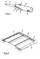
- the open roof construction comprises a movable closure means defined by a number of longitudinally extending panels 23, 24 and 25 which are transversally moveable between a central stacked position when the roof opening is opened and a adjoining position in which the roof opening is closed (illustrated).
- the two panels 23 and 25 positioned outermost in the closed state of the roof opening each comprise two locking mechanisms at the positions indicated by circles, i.e. at their forward and rearward edges, respectively, in the vicinity of their respective outer longitudinal edge 26.
- the locking mechanisms themselves have not been illustrated in figure 8.
Landscapes
- Engineering & Computer Science (AREA)
- Mechanical Engineering (AREA)
- General Engineering & Computer Science (AREA)
- Lock And Its Accessories (AREA)
- Snaps, Bayonet Connections, Set Pins, And Snap Rings (AREA)
Abstract
Description
Claims (15)
- Locking mechanism for locking together two parts, comprising a first movable locking member connected to a first one of said parts and a second locking member connected to a second one of said parts, wherein the first locking member is movable between a release position in which it disengages the second locking member and a locking position in which it lockingly engages the second locking member, characterized in that the first locking member comprises an elongate, substantially cylindrically shaped locking pin which can translate in its longitudinal direction and which can rotate around its longitudinal axis, wherein said locking pin is housed in a tubular guide member for defining the translational and rotational movements of the locking pin, and wherein the locking pin is operatively connected to a drive member for in combination with the guide member causing the movements of the locking pin relative to the guide member and thus relative to the second locking member.
- Locking mechanism according to claim 1, wherein the guide member comprises at least one guide channel with a first longitudinal section and a connecting transverse section, whereas the locking pin comprises a corresponding guide projection projecting into said guide channel.
- Locking mechanism according to claim 2, wherein the guide member comprises two guide channels positioned one diametrically opposite the other, whereas the locking pin correspondingly comprises two guide projections positioned one diametrically opposite the other.
- Locking mechanism according to claim 2 or 3, wherein the drive member comprises a drive pin movable in the longitudinal direction of the locking pin, with at least one drive projection that engages the locking pin.
- Locking mechanism according to claim 4, wherein the locking pin comprises a longitudinally extending bore for at least partially housing the drive member.
- Locking mechanism according to claim 5, wherein the locking pin comprises at least one spiral shaped channel into which the drive projection of the drive pin extends and wherein means are provided for preventing a rotation of the drive pin relative to the guide member.
- Locking mechanism according to claim 6, wherein the means for preventing a rotation of the drive pin relative to the guide member comprises a longitudinally extending auxiliary channel provided in the guide member into which said drive projection of the drive pin extends.
- Locking mechanism according to claim 7, wherein the locking pin comprises two spiral shaped channels, the drive pin comprises two drive pins and the guide member comprises two auxiliary channels, each positioned one diametrically opposite the other.
- Locking mechanism according to any of the previous claims, wherein the locking pin is provided with at least one locking nose for cooperation with a locking recess of the second locking member.
- Locking mechanism according to claim 9, wherein said locking nose and locking recess together define a locking assembly of the bayonet type.
- Locking mechanism according to claim 9 or 10, wherein the locking pin comprises two locking noses and the second locking member comprises two locking recesses, each positioned one diametrically opposite the other.
- Locking mechanism according to any of the previous types, wherein said two parts belong to a vehicle.
- Locking mechanism according to claim 12, wherein said two parts belong to an open roof construction of a vehicle.
- Open roof construction for a vehicle, comprising a roof opening defined in a stationary part of the vehicle and a movable closure means for opening and closing said roof opening, provided with at least one locking mechanism according any of the previous claims, wherein one of said first and second locking members is connected to the stationary part of the vehicle and the other of said first and second locking members is connected to the movable closure means.
- Open roof construction according to claim 14, wherein the movable closure means comprises a number of longitudinally extending panels which are transversally movable between a central stacked position when the roof opening is opened and an adjoining position in which the roof opening is closed, and wherein the two panels that are positioned outermost in the closed state of the roof opening each comprise two locking mechanisms positioned at their forward and rearward edges, respectively, in the vicinity of their respective outer longitudinal edge.
Priority Applications (3)
| Application Number | Priority Date | Filing Date | Title |
|---|---|---|---|
| DE602004006486T DE602004006486T2 (en) | 2004-03-29 | 2004-03-29 | Locking mechanism and a sunroof equipped therewith |
| EP04101280A EP1582752B1 (en) | 2004-03-29 | 2004-03-29 | Locking mechanism and open roof construction provided therewith |
| JP2005096046A JP4969790B2 (en) | 2004-03-29 | 2005-03-29 | Lock mechanism and open roof structure provided with the same |
Applications Claiming Priority (1)
| Application Number | Priority Date | Filing Date | Title |
|---|---|---|---|
| EP04101280A EP1582752B1 (en) | 2004-03-29 | 2004-03-29 | Locking mechanism and open roof construction provided therewith |
Publications (2)
| Publication Number | Publication Date |
|---|---|
| EP1582752A1 true EP1582752A1 (en) | 2005-10-05 |
| EP1582752B1 EP1582752B1 (en) | 2007-05-16 |
Family
ID=34878298
Family Applications (1)
| Application Number | Title | Priority Date | Filing Date |
|---|---|---|---|
| EP04101280A Expired - Lifetime EP1582752B1 (en) | 2004-03-29 | 2004-03-29 | Locking mechanism and open roof construction provided therewith |
Country Status (3)
| Country | Link |
|---|---|
| EP (1) | EP1582752B1 (en) |
| JP (1) | JP4969790B2 (en) |
| DE (1) | DE602004006486T2 (en) |
Cited By (4)
| Publication number | Priority date | Publication date | Assignee | Title |
|---|---|---|---|---|
| ITNA20080051A1 (en) * | 2008-08-25 | 2010-02-26 | Francesco Chioccola | CONNECTION SYSTEM OF JOINTS WITH SIMPLE OVERLAY WITH AUTOMATIC SETTING. |
| WO2021141520A1 (en) * | 2020-01-08 | 2021-07-15 | Saab Ab | Fastener for pyrotechnical dispenser magazine |
| CN113853316A (en) * | 2019-05-17 | 2021-12-28 | 韦巴斯托股份公司 | Assembly and method for moving cover |
| WO2023165788A1 (en) * | 2022-03-01 | 2023-09-07 | Webasto SE | Assembly for moving a cover |
Families Citing this family (3)
| Publication number | Priority date | Publication date | Assignee | Title |
|---|---|---|---|---|
| EP2607125B2 (en) * | 2011-12-22 | 2017-03-01 | Inalfa Roof Systems Group B.V. | Locking mechanism for open roof construction and open roof construction provided therewith |
| KR101627918B1 (en) * | 2014-06-30 | 2016-06-07 | 주식회사 엘지씨엔에스 | Apparatus for locking door of safe |
| DE102017128601A1 (en) * | 2017-12-01 | 2019-06-06 | Technische Universität Darmstadt | Shaft coupling mechanism for engaging and disengaging by the given degrees of freedom translation and rotation |
Citations (2)
| Publication number | Priority date | Publication date | Assignee | Title |
|---|---|---|---|---|
| US2794961A (en) * | 1952-06-26 | 1957-06-04 | Servo Corp Of America | Detachable joint for a mast or the like |
| US3466715A (en) * | 1967-06-05 | 1969-09-16 | Norco Inc | Releasable plug-and-socket fastener |
Family Cites Families (5)
| Publication number | Priority date | Publication date | Assignee | Title |
|---|---|---|---|---|
| JPS6315608Y2 (en) * | 1984-12-30 | 1988-05-02 | ||
| FR2628488B1 (en) * | 1988-03-14 | 1990-12-28 | Ecia Equip Composants Ind Auto | QUICK ATTACHMENT OF THE IMPROVED BAYONET TYPE |
| JPH039470U (en) * | 1989-06-16 | 1991-01-29 | ||
| DE10023864B4 (en) * | 2000-05-16 | 2005-06-23 | Webasto Ag | Folding hood of a vehicle |
| JP2002106530A (en) * | 2000-09-29 | 2002-04-10 | Nippon Plast Co Ltd | Fixture of parts |
-
2004
- 2004-03-29 EP EP04101280A patent/EP1582752B1/en not_active Expired - Lifetime
- 2004-03-29 DE DE602004006486T patent/DE602004006486T2/en not_active Expired - Lifetime
-
2005
- 2005-03-29 JP JP2005096046A patent/JP4969790B2/en not_active Expired - Fee Related
Patent Citations (2)
| Publication number | Priority date | Publication date | Assignee | Title |
|---|---|---|---|---|
| US2794961A (en) * | 1952-06-26 | 1957-06-04 | Servo Corp Of America | Detachable joint for a mast or the like |
| US3466715A (en) * | 1967-06-05 | 1969-09-16 | Norco Inc | Releasable plug-and-socket fastener |
Cited By (5)
| Publication number | Priority date | Publication date | Assignee | Title |
|---|---|---|---|---|
| ITNA20080051A1 (en) * | 2008-08-25 | 2010-02-26 | Francesco Chioccola | CONNECTION SYSTEM OF JOINTS WITH SIMPLE OVERLAY WITH AUTOMATIC SETTING. |
| CN113853316A (en) * | 2019-05-17 | 2021-12-28 | 韦巴斯托股份公司 | Assembly and method for moving cover |
| CN113853316B (en) * | 2019-05-17 | 2024-05-03 | 韦巴斯托股份公司 | Assembly and method for moving a cover |
| WO2021141520A1 (en) * | 2020-01-08 | 2021-07-15 | Saab Ab | Fastener for pyrotechnical dispenser magazine |
| WO2023165788A1 (en) * | 2022-03-01 | 2023-09-07 | Webasto SE | Assembly for moving a cover |
Also Published As
| Publication number | Publication date |
|---|---|
| JP4969790B2 (en) | 2012-07-04 |
| JP2005282860A (en) | 2005-10-13 |
| DE602004006486T2 (en) | 2008-02-14 |
| EP1582752B1 (en) | 2007-05-16 |
| DE602004006486D1 (en) | 2007-06-28 |
Similar Documents
| Publication | Publication Date | Title |
|---|---|---|
| EP1121506B1 (en) | File interlock system and mechanism | |
| EP2017108B1 (en) | Open roof construction for a vehicle | |
| KR102751308B1 (en) | Vehicle door handle assembly | |
| US9704607B2 (en) | Highly safe control mechanism for a device for the sealed transfer between two closed spaces | |
| EP1582752B1 (en) | Locking mechanism and open roof construction provided therewith | |
| US20020060461A1 (en) | System for opening and closing sliding door | |
| JP2019118788A (en) | Slide rail assembly and rail kit thereof | |
| KR101821243B1 (en) | Latch system for door of vehicle | |
| US20110197648A1 (en) | Crimping tool head | |
| US7249452B2 (en) | Cable or the like protection and guide device | |
| CN101990692B (en) | An actuator device and an electric switch device provided therewith | |
| ITTO20000405A1 (en) | CAR DOOR HANDLE IN PARTICULAR OF THE TYPE HAVING A REST POSITION, AN OPENING POSITION AND AT A POSITION OF | |
| US7144077B2 (en) | Mechanism for a sun roof | |
| CN111051631A (en) | Latch device | |
| JP2000052774A (en) | Vehicle roof | |
| US8806908B2 (en) | Dual key bi-step lock | |
| CN1942646B (en) | Turn-tilt window | |
| US11050181B2 (en) | Electric terminal connector assembly with a terminal lock | |
| EP0933668A3 (en) | Compact camera | |
| JP2008533333A (en) | Releasable lock for automotive locking system | |
| CN102191890B (en) | There is the mortise lock of selectable functions | |
| EP3564054B1 (en) | Locking mechanism and open roof construction provided therewith | |
| EP1582388A1 (en) | Locking mechanism and open roof construction provided therewith | |
| KR200381043Y1 (en) | Locking and unlocking device of door lock | |
| US20250100355A1 (en) | Assembly and method for moving a cover |
Legal Events
| Date | Code | Title | Description |
|---|---|---|---|
| PUAI | Public reference made under article 153(3) epc to a published international application that has entered the european phase |
Free format text: ORIGINAL CODE: 0009012 |
|
| AK | Designated contracting states |
Kind code of ref document: A1 Designated state(s): AT BE BG CH CY CZ DE DK EE ES FI FR GB GR HU IE IT LI LU MC NL PL PT RO SE SI SK TR |
|
| AX | Request for extension of the european patent |
Extension state: AL LT LV MK |
|
| 17P | Request for examination filed |
Effective date: 20060317 |
|
| AKX | Designation fees paid |
Designated state(s): DE FR GB |
|
| 111Z | Information provided on other rights and legal means of execution |
Free format text: ATBEBGCHCYCZDEDKEEESFIFRGBGRHUIEITLUMCNLPLPTROSESISKTR Effective date: 20060531 |
|
| GRAP | Despatch of communication of intention to grant a patent |
Free format text: ORIGINAL CODE: EPIDOSNIGR1 |
|
| GRAS | Grant fee paid |
Free format text: ORIGINAL CODE: EPIDOSNIGR3 |
|
| GRAA | (expected) grant |
Free format text: ORIGINAL CODE: 0009210 |
|
| AK | Designated contracting states |
Kind code of ref document: B1 Designated state(s): DE FR GB |
|
| REG | Reference to a national code |
Ref country code: GB Ref legal event code: FG4D |
|
| REF | Corresponds to: |
Ref document number: 602004006486 Country of ref document: DE Date of ref document: 20070628 Kind code of ref document: P |
|
| ET | Fr: translation filed | ||
| PLBE | No opposition filed within time limit |
Free format text: ORIGINAL CODE: 0009261 |
|
| STAA | Information on the status of an ep patent application or granted ep patent |
Free format text: STATUS: NO OPPOSITION FILED WITHIN TIME LIMIT |
|
| 26N | No opposition filed |
Effective date: 20080219 |
|
| PGFP | Annual fee paid to national office [announced via postgrant information from national office to epo] |
Ref country code: GB Payment date: 20080317 Year of fee payment: 5 |
|
| PGFP | Annual fee paid to national office [announced via postgrant information from national office to epo] |
Ref country code: FR Payment date: 20080229 Year of fee payment: 5 |
|
| GBPC | Gb: european patent ceased through non-payment of renewal fee |
Effective date: 20090329 |
|
| REG | Reference to a national code |
Ref country code: FR Ref legal event code: ST Effective date: 20091130 |
|
| PG25 | Lapsed in a contracting state [announced via postgrant information from national office to epo] |
Ref country code: FR Free format text: LAPSE BECAUSE OF NON-PAYMENT OF DUE FEES Effective date: 20091123 Ref country code: GB Free format text: LAPSE BECAUSE OF NON-PAYMENT OF DUE FEES Effective date: 20090329 |
|
| PGFP | Annual fee paid to national office [announced via postgrant information from national office to epo] |
Ref country code: DE Payment date: 20230329 Year of fee payment: 20 |
|
| REG | Reference to a national code |
Ref country code: DE Ref legal event code: R071 Ref document number: 602004006486 Country of ref document: DE |