EP1582718A1 - Procede et systeme de commande du fonctionnement d'un moteur a combustion interne de vehicule automobile - Google Patents
Procede et systeme de commande du fonctionnement d'un moteur a combustion interne de vehicule automobile Download PDFInfo
- Publication number
- EP1582718A1 EP1582718A1 EP05300224A EP05300224A EP1582718A1 EP 1582718 A1 EP1582718 A1 EP 1582718A1 EP 05300224 A EP05300224 A EP 05300224A EP 05300224 A EP05300224 A EP 05300224A EP 1582718 A1 EP1582718 A1 EP 1582718A1
- Authority
- EP
- European Patent Office
- Prior art keywords
- engine
- adm
- setpoint
- pressure
- intake
- Prior art date
- Legal status (The legal status is an assumption and is not a legal conclusion. Google has not performed a legal analysis and makes no representation as to the accuracy of the status listed.)
- Granted
Links
Images


Classifications
-
- F—MECHANICAL ENGINEERING; LIGHTING; HEATING; WEAPONS; BLASTING
- F02—COMBUSTION ENGINES; HOT-GAS OR COMBUSTION-PRODUCT ENGINE PLANTS
- F02D—CONTROLLING COMBUSTION ENGINES
- F02D41/00—Electrical control of supply of combustible mixture or its constituents
- F02D41/0002—Controlling intake air
-
- F—MECHANICAL ENGINEERING; LIGHTING; HEATING; WEAPONS; BLASTING
- F02—COMBUSTION ENGINES; HOT-GAS OR COMBUSTION-PRODUCT ENGINE PLANTS
- F02D—CONTROLLING COMBUSTION ENGINES
- F02D23/00—Controlling engines characterised by their being supercharged
- F02D23/02—Controlling engines characterised by their being supercharged the engines being of fuel-injection type
-
- F—MECHANICAL ENGINEERING; LIGHTING; HEATING; WEAPONS; BLASTING
- F02—COMBUSTION ENGINES; HOT-GAS OR COMBUSTION-PRODUCT ENGINE PLANTS
- F02D—CONTROLLING COMBUSTION ENGINES
- F02D41/00—Electrical control of supply of combustible mixture or its constituents
- F02D41/0002—Controlling intake air
- F02D41/0007—Controlling intake air for control of turbo-charged or super-charged engines
-
- F—MECHANICAL ENGINEERING; LIGHTING; HEATING; WEAPONS; BLASTING
- F02—COMBUSTION ENGINES; HOT-GAS OR COMBUSTION-PRODUCT ENGINE PLANTS
- F02D—CONTROLLING COMBUSTION ENGINES
- F02D41/00—Electrical control of supply of combustible mixture or its constituents
- F02D41/0025—Controlling engines characterised by use of non-liquid fuels, pluralities of fuels, or non-fuel substances added to the combustible mixtures
- F02D41/0047—Controlling exhaust gas recirculation [EGR]
- F02D41/005—Controlling exhaust gas recirculation [EGR] according to engine operating conditions
- F02D41/0052—Feedback control of engine parameters, e.g. for control of air/fuel ratio or intake air amount
-
- F—MECHANICAL ENGINEERING; LIGHTING; HEATING; WEAPONS; BLASTING
- F02—COMBUSTION ENGINES; HOT-GAS OR COMBUSTION-PRODUCT ENGINE PLANTS
- F02B—INTERNAL-COMBUSTION PISTON ENGINES; COMBUSTION ENGINES IN GENERAL
- F02B37/00—Engines characterised by provision of pumps driven at least for part of the time by exhaust
- F02B37/12—Control of the pumps
-
- F—MECHANICAL ENGINEERING; LIGHTING; HEATING; WEAPONS; BLASTING
- F02—COMBUSTION ENGINES; HOT-GAS OR COMBUSTION-PRODUCT ENGINE PLANTS
- F02D—CONTROLLING COMBUSTION ENGINES
- F02D41/00—Electrical control of supply of combustible mixture or its constituents
- F02D41/0002—Controlling intake air
- F02D2041/0017—Controlling intake air by simultaneous control of throttle and exhaust gas recirculation
-
- F—MECHANICAL ENGINEERING; LIGHTING; HEATING; WEAPONS; BLASTING
- F02—COMBUSTION ENGINES; HOT-GAS OR COMBUSTION-PRODUCT ENGINE PLANTS
- F02D—CONTROLLING COMBUSTION ENGINES
- F02D2200/00—Input parameters for engine control
- F02D2200/02—Input parameters for engine control the parameters being related to the engine
- F02D2200/04—Engine intake system parameters
- F02D2200/0406—Intake manifold pressure
-
- F—MECHANICAL ENGINEERING; LIGHTING; HEATING; WEAPONS; BLASTING
- F02—COMBUSTION ENGINES; HOT-GAS OR COMBUSTION-PRODUCT ENGINE PLANTS
- F02D—CONTROLLING COMBUSTION ENGINES
- F02D2200/00—Input parameters for engine control
- F02D2200/02—Input parameters for engine control the parameters being related to the engine
- F02D2200/04—Engine intake system parameters
- F02D2200/0414—Air temperature
-
- F—MECHANICAL ENGINEERING; LIGHTING; HEATING; WEAPONS; BLASTING
- F02—COMBUSTION ENGINES; HOT-GAS OR COMBUSTION-PRODUCT ENGINE PLANTS
- F02D—CONTROLLING COMBUSTION ENGINES
- F02D41/00—Electrical control of supply of combustible mixture or its constituents
- F02D41/02—Circuit arrangements for generating control signals
- F02D41/18—Circuit arrangements for generating control signals by measuring intake air flow
- F02D41/187—Circuit arrangements for generating control signals by measuring intake air flow using a hot wire flow sensor
-
- F—MECHANICAL ENGINEERING; LIGHTING; HEATING; WEAPONS; BLASTING
- F02—COMBUSTION ENGINES; HOT-GAS OR COMBUSTION-PRODUCT ENGINE PLANTS
- F02M—SUPPLYING COMBUSTION ENGINES IN GENERAL WITH COMBUSTIBLE MIXTURES OR CONSTITUENTS THEREOF
- F02M26/00—Engine-pertinent apparatus for adding exhaust gases to combustion-air, main fuel or fuel-air mixture, e.g. by exhaust gas recirculation [EGR] systems
- F02M26/02—EGR systems specially adapted for supercharged engines
- F02M26/04—EGR systems specially adapted for supercharged engines with a single turbocharger
- F02M26/05—High pressure loops, i.e. wherein recirculated exhaust gas is taken out from the exhaust system upstream of the turbine and reintroduced into the intake system downstream of the compressor
-
- F—MECHANICAL ENGINEERING; LIGHTING; HEATING; WEAPONS; BLASTING
- F02—COMBUSTION ENGINES; HOT-GAS OR COMBUSTION-PRODUCT ENGINE PLANTS
- F02M—SUPPLYING COMBUSTION ENGINES IN GENERAL WITH COMBUSTIBLE MIXTURES OR CONSTITUENTS THEREOF
- F02M26/00—Engine-pertinent apparatus for adding exhaust gases to combustion-air, main fuel or fuel-air mixture, e.g. by exhaust gas recirculation [EGR] systems
- F02M26/02—EGR systems specially adapted for supercharged engines
- F02M26/09—Constructional details, e.g. structural combinations of EGR systems and supercharger systems; Arrangement of the EGR and supercharger systems with respect to the engine
- F02M26/10—Constructional details, e.g. structural combinations of EGR systems and supercharger systems; Arrangement of the EGR and supercharger systems with respect to the engine having means to increase the pressure difference between the exhaust and intake system, e.g. venturis, variable geometry turbines, check valves using pressure pulsations or throttles in the air intake or exhaust system
-
- F—MECHANICAL ENGINEERING; LIGHTING; HEATING; WEAPONS; BLASTING
- F02—COMBUSTION ENGINES; HOT-GAS OR COMBUSTION-PRODUCT ENGINE PLANTS
- F02M—SUPPLYING COMBUSTION ENGINES IN GENERAL WITH COMBUSTIBLE MIXTURES OR CONSTITUENTS THEREOF
- F02M26/00—Engine-pertinent apparatus for adding exhaust gases to combustion-air, main fuel or fuel-air mixture, e.g. by exhaust gas recirculation [EGR] systems
- F02M26/13—Arrangement or layout of EGR passages, e.g. in relation to specific engine parts or for incorporation of accessories
- F02M26/22—Arrangement or layout of EGR passages, e.g. in relation to specific engine parts or for incorporation of accessories with coolers in the recirculation passage
- F02M26/23—Layout, e.g. schematics
-
- Y—GENERAL TAGGING OF NEW TECHNOLOGICAL DEVELOPMENTS; GENERAL TAGGING OF CROSS-SECTIONAL TECHNOLOGIES SPANNING OVER SEVERAL SECTIONS OF THE IPC; TECHNICAL SUBJECTS COVERED BY FORMER USPC CROSS-REFERENCE ART COLLECTIONS [XRACs] AND DIGESTS
- Y02—TECHNOLOGIES OR APPLICATIONS FOR MITIGATION OR ADAPTATION AGAINST CLIMATE CHANGE
- Y02T—CLIMATE CHANGE MITIGATION TECHNOLOGIES RELATED TO TRANSPORTATION
- Y02T10/00—Road transport of goods or passengers
- Y02T10/10—Internal combustion engine [ICE] based vehicles
- Y02T10/12—Improving ICE efficiencies
-
- Y—GENERAL TAGGING OF NEW TECHNOLOGICAL DEVELOPMENTS; GENERAL TAGGING OF CROSS-SECTIONAL TECHNOLOGIES SPANNING OVER SEVERAL SECTIONS OF THE IPC; TECHNICAL SUBJECTS COVERED BY FORMER USPC CROSS-REFERENCE ART COLLECTIONS [XRACs] AND DIGESTS
- Y02—TECHNOLOGIES OR APPLICATIONS FOR MITIGATION OR ADAPTATION AGAINST CLIMATE CHANGE
- Y02T—CLIMATE CHANGE MITIGATION TECHNOLOGIES RELATED TO TRANSPORTATION
- Y02T10/00—Road transport of goods or passengers
- Y02T10/10—Internal combustion engine [ICE] based vehicles
- Y02T10/40—Engine management systems
Definitions
- the present invention relates to a method and a system for control of the operation of an internal combustion engine of motor vehicle.
- Controlling the operation of a combustion engine internal is to manage the engine from a set of sensors and actuators.
- the set of control laws under form of software strategy and characterization parameters in the form of a motor calibration are usually stored in a calculator in the form of a electronic control unit.
- Such a system usually includes a set turbocharger with supercharger comprising a compressor and a turbine with variable geometry.
- the compressor feeds the engine in air at a pressure greater than the pressure atmospheric and the turbine is traversed by the gases exhaust from the engine.
- a turbocharger assembly comprises a turbine and a compressor to increase the amount of air admitted in the engine cylinders.
- the power provided by the gases turbine exhaust can be modulated by installing a relief valve or by providing a turbine with fins with a variable orientation so as to constitute a turbocharger variable geometry (TGV).
- TSV turbocharger variable geometry
- the compressor is mounted on a mechanical axis receiving also the turbine so that the compressor compresses the air who enters the admission splitter.
- a heat exchanger can be placed between the compressor and the engine intake manifold in order to cool the compressed air at the compressor outlet.
- Actuators are used to control the opening and the closing of the relief valves or the orientation of the fins of the turbine so as to modify the geometry of said turbine.
- the control signals of these actuators are provided by the unit electronic control.
- a catalyst can be placed in the exhaust line upstream of the particulate filter to oxidize the gear units present at the output of the engine, such as unburned hydrocarbons and carbon monoxide. Such catalyst is effective only above a certain temperature, where the elimination of the reducing agents is active, and the catalyst is initiated.
- a bypass circuit allowing the recycling of a part exhaust gas comprises a valve which modulates the amount of exhaust gas recycled in the intake distributor.
- a filter In order to reduce the amount of particles released into exhaust gas, provision may be made for mounting a filter to particles in the exhaust pipe.
- a filter includes a set of microchannels in which a large Part of the particles is trapped. When the filter is saturated in particulates, it should be emptied by burning the particles during a regeneration phase which can be implemented at means of a heating device or by a specific adjustment of the engine.
- a servocontrol of the flow supplying fresh air from the motor to a flow setpoint engine fresh air supply helps reduce the production of nitrogen oxides and maintain a particle rate acceptable.
- An example of such an enslavement is elsewhere described in French patent application FR 2 829 530 (Renault).
- the object of the invention is to regulate the intake pressure in order to increase the richness of exhaust fuel, and therefore the output thermal level of the engine, in order to increase the heat energy to the exhaust when the catalyst is cold, and reduce the quantities hydrocarbons and carbon monoxide released.
- a method of controlling the operation of a motor internal combustion of a motor vehicle equipped with a set turbocharger, a part of the exhaust gases engine being recycled to the engine intake We measure the fresh air supply flow to the engine, the pressure and the gas inlet temperature. We enslave the flow supplying fresh air from the motor to a flow setpoint supply of fresh air to the engine, modulating a rate of engine exhaust gas recirculation, and the pressure is enslaved of admission of gases to an intake pressure gas, by modulating a fresh air supply rate of the engine by control of the positioning of the intake flap of a valve controlled regulation of the air supply flow of the engine. Positioning is calculated from a pre-positioning of the intake flap of said controlled valve.
- Pre-positioning makes it possible to anticipate variations in the set pressure of the gas intake, and to obtain a better enslavement in transient regime.
- the rate modulation engine exhaust gas recirculation is carried out by order of a controlled valve for regulating the recycling flow rate of engine exhaust gas.
- pre-positioning of the intake flap of the valve being controlled is a parameter function including an effective section objective of the intake flap of the valve controlled.
- the cross-section objective of the intake flap of the controlled valve is a Parameter function including the flow setpoint engine fresh air supply, the intake pressure of gas, the gas inlet temperature, and an air pressure in upstream of the inlet flap of the controlled control valve the air supply flow of the engine.
- the pressure of the gas upstream of the intake flap of the valve controlled from regulating the air supply flow of the engine is a parameter function comprising an air mass upstream of the intake flap of the controlled flow control valve engine air supply, intake temperature of gas, a constant mass of air, and the volume of the portion the upstream air circuit of the valve intake flap controlled regulation of the air supply flow of the engine.
- the instruction of gas inlet pressure is a function of parameters including the fuel flow rate of the engine, the motor rotation speed, and the fluid temperature of engine cooling.
- the command positioning of the intake flap of the controlled valve of regulating the flow rate of the engine air supply depends on the difference between the gas inlet pressure setpoint and the gas inlet pressure, the derivative of said difference between the set point of the gas inlet pressure and the pressure of the admission of the gases, of the integral over a period of time of said difference between the gas intake pressure setpoint and the gas inlet pressure, and said pre-positioning.
- the instruction of fresh air supply flow of the engine is a function of parameters including the fuel flow rate of the motor, and the rotational speed of the motor.
- a system for controlling the operation of an engine internal combustion of a motor vehicle equipped with a set turbocharger, a part of the exhaust gases engine being recycled to the engine intake includes an electronic control unit capable of performing calculations from stored data and measured values, a sensor to measure the fresh air supply flow of the engine, a sensor to measure the gas inlet pressure of the engine, a sensor to measure the temperature of admission engine gases, and a valve controlled intake flap, regulating the air supply flow of the engine.
- the unit of electronic control comprising servo means the flow of fresh air supply of the engine to a set of flow rate of fresh air from the engine, and means servocontrol of the gas inlet pressure on a gas pressure set point, able to modulate a rate of fresh air supply of the engine by control of the positioning of the intake flap of a valve controlled from regulating the air supply flow of the engine, said positioning being calculated from a pre-positioning of the intake flap of said controlled valve.
- the means enslavement of the gas inlet pressure include means for calculating a predetermined pressure setpoint gas intake, and control means of the positioning of the intake flap of the controlled valve of regulation of the air supply flow of the engine.
- the means of control include means for calculating a pre-positioning the intake flap of said controlled valve.
- FIG. 1 there is shown a motor with internal combustion 1 to four cylinders, each cylinder being associated with a fuel injection device, referenced 2.
- the air fresh penetrating into the intake manifold 3 of the engine 1 crosses beforehand a turbocharger 4 comprising a compressor 5 and a turbine 6 mounted on a common shaft 7.
- the flow rates provided by compressor 5 and turbine 6 are controlled by an electronic control unit 8.
- the engine 1 comprises a sensor 12 for measuring the temperature Ad adm intake gas admission inlet manifold 3, and a sensor 13 for measuring the inlet pressure P adm intake gas inlet manifold 3.
- the compressed air from the compressor 5 passes through a heat exchanger 14 which allows to cool the admitted gases.
- the cooled compressed air passes through a controlled valve 15 for regulating the air supply flow rate of the engine 1.
- the controlled valve 15 comprises an intake flap 15a, making it possible to vary the flow rate.
- the compressed air flows from the compressor 5 to the inlet distributor 3 via a duct 16 which passes through the heat exchanger 14 and comprises the controlled valve 15.
- the gases coming from the exhaust manifold 17, after combustion in the engine 1, by a conduit 18 are directed in part towards the conduit 16 by a conduit 19, so as to be partly recycled after mixing in the intake air duct 16 directed to the intake manifold 3.
- This part of the exhaust gases from the motor 1 is cooled by passing through a heat exchanger 20, then through a controlled valve 21 for regulating the flow of engine exhaust gas recirculation 1.
- the controlled valve 21 comprises an intake flap 21a, making it possible to vary the debit.
- the other part of the engine 1 output gas flows through a duct 22, to the turbine 6 to drive the compressor 5.
- the gases circulate in a conduit 23, through a catalytic device 24 making it possible to reduce hydrocarbon and carbon monoxide levels of the exhaust gases 1.
- the gases then pass through a particulate filter 25 before being released into the atmosphere by the muffler 26.
- the electronic control unit 8 comprises, so conventional, a microprocessor or CPU, memories vivid, dead memories, converters analog / digital and different input and output interfaces exit.
- the electronic control unit 8 receives various signals allowing the operation of the system.
- the electronic control unit 8 receives in particular via the connection 27a a signal from the temperature sensor 12 indicating the value of the admission temperature T adm of the gases, and through the connection 27b a signal from the pressure sensor 13 indicating the value the pressure P adm of the admission of gases.
- the flow rate Q air supply air_frais costs of the engine 1 measured by the flow meter 10 is fed as a signal via the connection 27c to the electronic control unit 8.
- the electronic control unit 8 emits various signals making it possible to manage the operation of the engine 1 as well as other vehicle components, not shown in FIG. 1.
- the electronic control unit 8 emits, in particular via the connection 28, a control signal for controlling the valve 15, and transmits via the connection 29, a control signal for controlling the valve 21.
- the electronic control unit 8 regulates the boost pressure by acting on the orientation of internal fins 5 and / or the turbine 6 by means of the connections 30 and 31.
- the electronic control unit 8 also emits, via a connection 32, a control signal for a regulator 33 of the flow rate Q carb of fuel injected into the motor 1 by the different injection devices 2.
- the regulator 33 is capable of measuring the flow rate Q carb of fuel injected into the engine 1. For this purpose, the fuel coming from the vehicle tank is supplied to the engine 1.
- the electronic control unit 8 further receives, by a connection 36, a signal indicating the value of the rotational speed N Motor Motor 1.
- the electronic control unit 8 also includes a connection 37 providing vehicle speed information.
- the system also comprises a sensor 38, for measuring the temperature T 1r of the cooling fluid of the engine 1, connected to the electronic control unit 8 via a connection 40.
- the electronic control unit 8 further comprises means 42 for controlling the flow rate Q air_frais fresh air supply of the engine 1, and means 43 for servocontrolling the pressure P adm for the admission of the gases.
- the means 43 for servocontrolling the pressure P adm for the admission of the gases comprise calculating means 43a of a predetermined setpoint P setpoint / adm of the gas intake pressure, and control means 43b for positioning the flap. 15a admission of the controlled valve 15.
- the control means 43b comprise calculating means 43c of a pre-positioning of the intake flap 15a of the controlled valve 15b.
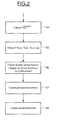
- FIG. 2 represents a servocontrol of the pressure P adm of admission of the gases to a setpoint P set / adm of the gas intake pressure, according to one aspect of the invention.
- step 44 a calculation is made of the setpoint P setpoint / adm of the gas intake pressure by using a parameter function which comprises the rotation speed N engine of the engine 1 in revolutions / minute, the flow rate Q carb engine fuel supply 1 in kg / s, and the temperature T lr of the engine coolant 1 in K.
- step 45 the pressure P adm of the admission of the gases, the temperature T adm of the admission of the gases, and the flow rate Q air of the fresh air supply of the engine 1 are measured .
- step 46 the proportional, integral and derivative terms of the difference ⁇ Padm are calculated between the setpoint P set / adm of the gas inlet pressure and the admission pressure P adm of the gases used.
- the difference ⁇ Padm is calculated between the calculated setpoint P set / admde the gas inlet pressure and the measured pressure P adm of the gas inlet, the derivative of the difference ⁇ Padm between the calculated setpoint P set / adm of the gas inlet pressure and the measured pressure P adm of the gas inlet, and the integral over a time interval of said difference ⁇ Padm between the calculated setpoint P setpoint / adm of the pressure of d admission of the gases and the measured pressure P adm of the admission of the gases.
- step 47 the pre-positioning of the intake flap 15a of the controlled valve 15 for regulating the air supply flow rate of the engine 1 is calculated, and in step 48, the positioning of the flap d is calculated.
- FIG. 3 represents steps composing step 47 of FIG. pre-positioning calculation of the intake flap 15a of the valve controlled the flow rate of the air supply of the motor 1.
- step 47a the setpoint Q setpoint / air_fresh of fresh air supply flow rate of the engine 1 is calculated as a function of parameters comprising the flow rate Q carb of the fuel supply of the engine 1 in kg / s, and the speed N motor rotation speed 1, in revolutions / min.
- step 47b the upstream pressure P is estimated upstream of the intake flap 15a of the controlled valve 15 for regulating the air supply flow rate of the engine 1.
- the objective cross-section S elf_obj of the admission flap 15a is calculated in step 47c.
- objective cross section is meant an effective section setpoint.
- the objective cross-section makes it possible to introduce into the pre-positioning calculation the dimensional characteristics of the intake flap 15a of said controlled valve 15.
- step 47d the pre-positioning is calculated as a function of parameters including the objective cross-section S eff obj obj of the admission flap 15a calculated in step 47c.
- This calculation is for example carried out by means of the following relation: in which BSV is a predetermined function, for example by means of a memorized table, simplification of the Barré Saint Venant formula.
- the air flow rate is the setpoint Q setpoint / air_fresh fresh air supply flow of the engine 1
- the pressure downstream of the intake flap 15a is the setpoint P setpoint / adm of the intake pressure of the gases
- the temperature upstream of the intake flap 15a is equal to the admission temperature T adm of the gases
- the effective cross section is the effective cross section S eff_obj of the intake flap 15a.
- FIG. 4 represents a calculation loop of step 47b for estimating the pressure P upstream upstream of the intake flap 15a, represented in FIG. 3.
- the invention thus makes it possible to reduce the quantities of hydrocarbons released into the atmosphere by gases engine exhaust.
- the invention also makes it possible to increase the richness of exhaust fuel, so the heat energy to exhaust, and thus reduce the priming time of the catalyst, and the cost of precious metals.
Landscapes
- Engineering & Computer Science (AREA)
- Chemical & Material Sciences (AREA)
- Combustion & Propulsion (AREA)
- Mechanical Engineering (AREA)
- General Engineering & Computer Science (AREA)
- Output Control And Ontrol Of Special Type Engine (AREA)
- Supercharger (AREA)
- Control Of Throttle Valves Provided In The Intake System Or In The Exhaust System (AREA)
- Exhaust-Gas Circulating Devices (AREA)
- Control Of Vehicle Engines Or Engines For Specific Uses (AREA)
Abstract
Description
- la figure 1 est une vue schématique d'un mode de réalisation d'un système selon un aspect de l'invention ;
- la figure 2 illustre un asservissement de la pression d'admission des gaz sur une consigne calculée de pression d'admission des gaz, selon un aspect de l'invention ;
- la figure 3 illustre une étape de calcul du pré-positionnement de l'asservissement représenté sur la figure 2 ; et
- la figure 4 illustre une étape d'estimation de pression amont représenté sur la figure 3.

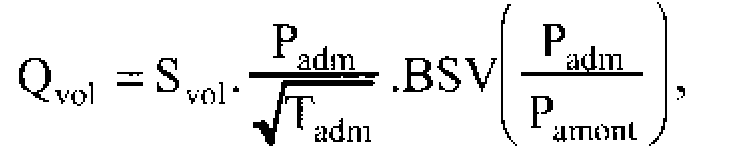
Svol est la section efficace du volet d'admission 15a, en m2, fonction prédéterminée d'une position Pos mesurée du volet d'admission 15a, par exemple en radians par rapport à un position de référence horizontale, et calculée à l'étape 47g.
Claims (10)
- Procédé de commande du fonctionnement d'un moteur à combustion interne de véhicule automobile équipé d'un ensemble turbocompresseur (4) de suralimentation, une partie des gaz de sortie du moteur étant recyclés à l'admission du moteur, caractérisé par le fait que :on mesure le débit (Qair_frais) d'alimentation en air frais du moteur (1) ;on mesure la pression (Padm) et la température (Tadm) d'admission des gaz ;on asservit le débit (Qair_frais) d'alimentation en air frais du moteur (1) sur une consigne (Q consigne / air_frais) de débit d'alimentation en air frais du moteur (1), en modulant un taux de recyclage de gaz de sortie du moteur (1) ; eton asservit la pression (Padm) d'admission des gaz sur une consigne (P consigne / adm) de pression d'admission des gaz, en modulant un taux d'air frais d'alimentation du moteur (1) par commande du positionnement du volet d'admission (15a) d'une vanne commandée (15) de régulation du débit d'alimentation en air du moteur (1), ledit positionnement étant calculé à partir d'un pré-positionnement du volet d'admission (15a) de ladite vanne commandée (15).
- Procédé selon la revendication 1, caractérisé par le fait que la modulation du taux de recyclage de gaz de sortie du moteur (1) s'effectue par commande d'une vanne commandée (21) de régulation du débit de recyclage des gaz de sortie du moteur (1).
- Procédé selon la revendication 1 ou 2, caractérisé par le fait que ledit pré-positionnement du volet d'admission (15a) de la vanne commandée (15) est une fonction de paramètres comprenant une section efficace objective (Seff_obj) du volet d'admission de la vanne commandée (15).
- Procédé selon la revendication 3, caractérisé par le fait que ladite section efficace objective (Seff_obj) du volet d'admission (15a) de la vanne commandée (15) est une fonction de paramètres comprenant la consigne (Q consigne / air_frais) de débit d'alimentation en air frais du moteur (1), la pression (Padm) d'admission des gaz, la température (Tadm) d'admission des gaz, et une pression (Pamont) de l'air en amont du volet d'admission (15a) de la vanne commandée (15) de régulation du débit d'alimentation en air du moteur (1).
- Procédé selon la revendication 4, caractérisé par le fait que ladite pression (Pamont) des gaz en amont du volet d'admission (15a) de la vanne commandée (15) de régulation du débit d'alimentation en air du moteur (1) est une fonction de paramètres comprenant une masse d'air (Mair_amont) en amont du volet d'admission (15a) de la vanne commandée (15) de régulation du débit d'alimentation en air du moteur (1), de la température (Tadm) d'admission des gaz, d'une constante massique (Rair) de l'air, et du volume de la portion du circuit d'air amont du volet d'admission (15a) de la vanne commandée (15) de régulation du débit d'alimentation en air du moteur (1).
- Procédé selon l'une quelconque des revendications 1 à 5, caractérisé par le fait que la consigne (P consigne / adm) de pression d'admission des gaz est une fonction de paramètres comprenant le débit (Qcarb) d'alimentation en carburant du moteur (1), la vitesse de rotation (Nmoteur) du moteur (1), et la température (Tlr) du fluide de refroidissement du moteur (1).
- Procédé selon l'une quelconque des revendications 3 à 6, caractérisé par le fait que la commande du positionnement du volet d'admission (15a) de la vanne commandée (15) de régulation du débit d'alimentation en air du moteur (1) dépend de la différence (εPadm) entre la consigne (P consigne / adm) de pression d'admission des gaz et la pression (Padm) d'admission des gaz, de la dérivée de ladite différence (εPadm) entre la consigne (P consigne / adm) de pression d'admission des gaz et la pression (Padm) d'admission des gaz, de l'intégrale sur un intervalle de temps de ladite différence (εPadm) entre la consigne (P consigne / adm) de pression d'admission des gaz et la pression (Padm) d'admission des gaz, et dudit pré-positionnement.
- Procédé selon l'une quelconque des revendications 1 à 7, caractérisé par le fait que la consigne (Q consigne / air_frais) de débit d'alimentation en air frais du moteur (1) est une fonction de paramètres comprenant le débit (Qcarb) d'alimentation en carburant du moteur (1), et la vitesse de rotation (Nmoteur) du moteur (1).
- Système de commande du fonctionnement d'un moteur (1) à combustion interne de véhicule automobile équipé d'un ensemble turbocompresseur (4) de suralimentation, une partie des gaz de sortie du moteur étant recyclés à l'admission du moteur, caractérisé par le fait que le système comprend une unité de commande électronique (8) capable d'effectuer des calculs à partir de données mémorisées et de valeurs mesurées, un capteur (10) pour mesurer le débit (Qair_frais) d'alimentation en air frais du moteur (1), un capteur (13) pour mesurer la pression (Padm) d'admission des gaz du moteur (1), un capteur (12) pour mesurer la température (Tadm) d'admission des gaz du moteur (1), et une vanne commandée (15) à volet d'admission (15a), de régulation du débit d'alimentation en air du moteur (1), l'unité de commande électronique (8) comprenant des moyens d'asservissement (42) du débit (Qair_frais) d'alimentation en air frais du moteur (1) sur une consigne (Q consigne / air_frais) de débit d'alimentation en air frais du moteur (1), et des moyens d'asservissement (43) de la pression (Padm) d'admission des gaz sur une consigne (P consigne / adm) de pression d'admission des gaz, aptes à moduler un taux d'air frais d'alimentation du moteur (1) par commande du positionnement du volet d'admission (15a) d'une vanne commandée (15) de régulation du débit d'alimentation en air du moteur (1), ledit positionnement étant calculé à partir d'un pré-positionnement du volet d'admission (15a) de ladite vanne commandée (15).
- Système selon la revendication 9, caractérisé par le fait que lesdits moyens d'asservissement (43) de la pression (Padm) d'admission des gaz comprennent des moyens de calcul (43a) d'une consigne prédéterminée (P consigne / adm) de pression d'admission des gaz, et des moyens de commande (43b) du positionnement du volet d'admission (15a) de la vanne commandée (15) de régulation du débit d'alimentation en air du moteur (1), lesdits moyens de commande (43b) comprenant des moyens de calcul (43 c) d'un pré-positionnement du volet d'admission (15a) de ladite vanne commandée (15).
Applications Claiming Priority (2)
| Application Number | Priority Date | Filing Date | Title |
|---|---|---|---|
| FR0403234 | 2004-03-29 | ||
| FR0403234A FR2868126B1 (fr) | 2004-03-29 | 2004-03-29 | Procede et systeme de commande du fonctionnement d'un moteur a combustion interne de vehicule automobile equipe d'un ensemble turbocompresseur de suralimentation |
Publications (2)
| Publication Number | Publication Date |
|---|---|
| EP1582718A1 true EP1582718A1 (fr) | 2005-10-05 |
| EP1582718B1 EP1582718B1 (fr) | 2010-06-02 |
Family
ID=34878460
Family Applications (1)
| Application Number | Title | Priority Date | Filing Date |
|---|---|---|---|
| EP05300224A Expired - Lifetime EP1582718B1 (fr) | 2004-03-29 | 2005-03-25 | Procédé et système de commande du fonctionnement d'un moteur à combustion interne de véhicule automobile |
Country Status (4)
| Country | Link |
|---|---|
| EP (1) | EP1582718B1 (fr) |
| AT (1) | ATE470061T1 (fr) |
| DE (1) | DE602005021572D1 (fr) |
| FR (1) | FR2868126B1 (fr) |
Citations (4)
| Publication number | Priority date | Publication date | Assignee | Title |
|---|---|---|---|---|
| EP1024264A1 (fr) * | 1999-01-26 | 2000-08-02 | Ford Global Technologies, Inc. | Méthode de contrôle d'un moteur diesel turbochargé avec recirculation de gaz d'échappement |
| EP1024261A2 (fr) * | 1999-01-26 | 2000-08-02 | Ford Global Technologies, Inc. | Méthode de contrôle d'un moteur diesel turbochargé avec recirculation de gaz d'échappement et permettant une réduction du retard du turbocompresseur |
| FR2829185A1 (fr) * | 2001-09-04 | 2003-03-07 | Renault | Procede et dispositif de commande d'une soupape de reglage d'un flux de gaz d'echappement recircules dans le collecteur d'admission d'un moteur a combustion interne |
| FR2829530A1 (fr) * | 2001-09-12 | 2003-03-14 | Renault | Procede et systeme de reglage du flux d'air dans le collecteur d'admission d'un moteur a combustion interne d'un vehicule automobile |
-
2004
- 2004-03-29 FR FR0403234A patent/FR2868126B1/fr not_active Expired - Fee Related
-
2005
- 2005-03-25 EP EP05300224A patent/EP1582718B1/fr not_active Expired - Lifetime
- 2005-03-25 AT AT05300224T patent/ATE470061T1/de not_active IP Right Cessation
- 2005-03-25 DE DE602005021572T patent/DE602005021572D1/de not_active Expired - Lifetime
Patent Citations (4)
| Publication number | Priority date | Publication date | Assignee | Title |
|---|---|---|---|---|
| EP1024264A1 (fr) * | 1999-01-26 | 2000-08-02 | Ford Global Technologies, Inc. | Méthode de contrôle d'un moteur diesel turbochargé avec recirculation de gaz d'échappement |
| EP1024261A2 (fr) * | 1999-01-26 | 2000-08-02 | Ford Global Technologies, Inc. | Méthode de contrôle d'un moteur diesel turbochargé avec recirculation de gaz d'échappement et permettant une réduction du retard du turbocompresseur |
| FR2829185A1 (fr) * | 2001-09-04 | 2003-03-07 | Renault | Procede et dispositif de commande d'une soupape de reglage d'un flux de gaz d'echappement recircules dans le collecteur d'admission d'un moteur a combustion interne |
| FR2829530A1 (fr) * | 2001-09-12 | 2003-03-14 | Renault | Procede et systeme de reglage du flux d'air dans le collecteur d'admission d'un moteur a combustion interne d'un vehicule automobile |
Also Published As
| Publication number | Publication date |
|---|---|
| ATE470061T1 (de) | 2010-06-15 |
| DE602005021572D1 (de) | 2010-07-15 |
| FR2868126B1 (fr) | 2006-06-23 |
| EP1582718B1 (fr) | 2010-06-02 |
| FR2868126A1 (fr) | 2005-09-30 |
Similar Documents
| Publication | Publication Date | Title |
|---|---|---|
| EP1989426B1 (fr) | Procede et dispositif de controle de la suralimentation en air d'un moteur a combustion interne | |
| WO2007148007A1 (fr) | Systeme de recirculation de gaz d'echappement pour moteur a combustion du type diesel suralimente et procede de commande d'un tel moteur | |
| FR2915237A1 (fr) | Systeme et procede de commande d'un turbocompresseur de suralimentation pour moteur a combustion interne | |
| FR2956160A1 (fr) | Procede de controle d'un moteur a combustion thermique equipe de deux boucles de recirculation de gaz d'echappement | |
| FR2868127A1 (fr) | Procede et systeme de commande du fonctionnement d'un moteur a combustion interne de vehicule automobile equipe d'un ensemble turbocompresseur de suralimentation | |
| EP1582718B1 (fr) | Procédé et système de commande du fonctionnement d'un moteur à combustion interne de véhicule automobile | |
| FR2945318A1 (fr) | Systeme et procede de commande de la suralimentation d'un moteur a combustion interne | |
| EP1293658A1 (fr) | Procédé et système de réglage du flux d'air dans le collecteur d'admission d'un moteur à combustion interne d'un véhicule automobile | |
| EP1650420B1 (fr) | Système et procédé de régularisation de la régénération d'un filtre à particules de moteur à combustion interne | |
| EP1106804B1 (fr) | Procédé de commande d'un groupe motopropulseur de véhicules automobile pour augmenter la richesse des gaz d'échappement en phase de régénération d'un piège à oxydes d'azote. | |
| FR2868128A1 (fr) | Procede et systeme de commande du fonctionnement d'un moteur a combustion interne de vehicule automobile equipe d'un ensemble turbocompresseur de suralimentation | |
| FR2911635A1 (fr) | Moteur thermique equipe d'un turbocompresseur et de deux circuits de recirculation des gaz d'echappement de type haute pression et basse pression. | |
| EP1574694B1 (fr) | Dispositif et procédé de régulation du débit de carburant injecté dans un moteur diesel | |
| FR2923538A3 (fr) | Systeme et procede d'estimation de la pression en amont d'une turbine de turbocompresseur et moteur thermique associ associe | |
| WO2016156715A1 (fr) | Dispositif comportant un circuit de recirculation de gaz d'echappement | |
| FR2864579A1 (fr) | Moteur a combustion interne avec suralimentation pilotee et procede de pilotage de la suralimentation | |
| FR2923537A1 (fr) | Systeme et procede d'estimation de la pression en aval d'une turbine de turbocompresseur et moteur thermique associe | |
| EP1491750B1 (fr) | Procédé et dispositif de commande de régénération d'un filtre à particules catalytique | |
| FR2903735A1 (fr) | Systeme de commande d'un moteur a combustion du type diesel suralimente avec recirculation des gaz d'echappement | |
| FR2909719A1 (fr) | Moteur a combustion interne a controle de temperature des gaz de combustion et procede correspondant | |
| EP1430203A1 (fr) | Procede de regeneration d'un filtre a particules pour moteur a combustion interne | |
| FR2851615A1 (fr) | Dispositif et procede de regulation du debit de carburant injecte dans un moteur diesel | |
| FR2858020A1 (fr) | Procede de commande d'un moteur a combustion interne comprenant une derivation entre le compresseur et le collecteur | |
| FR2876732A1 (fr) | Systeme et procede de regulation de la regeneration d'un filtre a particules de moteur a combustion interne | |
| FR2855216A1 (fr) | Procede d'estimation de la pression des gaz dans un collecteur d'admission de moteur a combustion interne et dispositif de commande d'un tel moteur |
Legal Events
| Date | Code | Title | Description |
|---|---|---|---|
| PUAI | Public reference made under article 153(3) epc to a published international application that has entered the european phase |
Free format text: ORIGINAL CODE: 0009012 |
|
| AK | Designated contracting states |
Kind code of ref document: A1 Designated state(s): AT BE BG CH CY CZ DE DK EE ES FI FR GB GR HU IE IS IT LI LT LU MC NL PL PT RO SE SI SK TR |
|
| AX | Request for extension of the european patent |
Extension state: AL BA HR LV MK YU |
|
| 17P | Request for examination filed |
Effective date: 20060302 |
|
| AKX | Designation fees paid |
Designated state(s): AT BE BG CH CY CZ DE DK EE ES FI FR GB GR HU IE IS IT LI LT LU MC NL PL PT RO SE SI SK TR |
|
| 17Q | First examination report despatched |
Effective date: 20060921 |
|
| GRAP | Despatch of communication of intention to grant a patent |
Free format text: ORIGINAL CODE: EPIDOSNIGR1 |
|
| GRAS | Grant fee paid |
Free format text: ORIGINAL CODE: EPIDOSNIGR3 |
|
| GRAA | (expected) grant |
Free format text: ORIGINAL CODE: 0009210 |
|
| AK | Designated contracting states |
Kind code of ref document: B1 Designated state(s): AT BE BG CH CY CZ DE DK EE ES FI FR GB GR HU IE IS IT LI LT LU MC NL PL PT RO SE SI SK TR |
|
| REG | Reference to a national code |
Ref country code: GB Ref legal event code: FG4D Free format text: NOT ENGLISH |
|
| REG | Reference to a national code |
Ref country code: CH Ref legal event code: EP |
|
| REG | Reference to a national code |
Ref country code: IE Ref legal event code: FG4D Free format text: LANGUAGE OF EP DOCUMENT: FRENCH |
|
| REF | Corresponds to: |
Ref document number: 602005021572 Country of ref document: DE Date of ref document: 20100715 Kind code of ref document: P |
|
| REG | Reference to a national code |
Ref country code: NL Ref legal event code: VDEP Effective date: 20100602 |
|
| PG25 | Lapsed in a contracting state [announced via postgrant information from national office to epo] |
Ref country code: LT Free format text: LAPSE BECAUSE OF FAILURE TO SUBMIT A TRANSLATION OF THE DESCRIPTION OR TO PAY THE FEE WITHIN THE PRESCRIBED TIME-LIMIT Effective date: 20100602 Ref country code: SE Free format text: LAPSE BECAUSE OF FAILURE TO SUBMIT A TRANSLATION OF THE DESCRIPTION OR TO PAY THE FEE WITHIN THE PRESCRIBED TIME-LIMIT Effective date: 20100602 |
|
| LTIE | Lt: invalidation of european patent or patent extension |
Effective date: 20100602 |
|
| PG25 | Lapsed in a contracting state [announced via postgrant information from national office to epo] |
Ref country code: SI Free format text: LAPSE BECAUSE OF FAILURE TO SUBMIT A TRANSLATION OF THE DESCRIPTION OR TO PAY THE FEE WITHIN THE PRESCRIBED TIME-LIMIT Effective date: 20100602 Ref country code: FI Free format text: LAPSE BECAUSE OF FAILURE TO SUBMIT A TRANSLATION OF THE DESCRIPTION OR TO PAY THE FEE WITHIN THE PRESCRIBED TIME-LIMIT Effective date: 20100602 Ref country code: AT Free format text: LAPSE BECAUSE OF FAILURE TO SUBMIT A TRANSLATION OF THE DESCRIPTION OR TO PAY THE FEE WITHIN THE PRESCRIBED TIME-LIMIT Effective date: 20100602 |
|
| PG25 | Lapsed in a contracting state [announced via postgrant information from national office to epo] |
Ref country code: CY Free format text: LAPSE BECAUSE OF FAILURE TO SUBMIT A TRANSLATION OF THE DESCRIPTION OR TO PAY THE FEE WITHIN THE PRESCRIBED TIME-LIMIT Effective date: 20100602 Ref country code: PL Free format text: LAPSE BECAUSE OF FAILURE TO SUBMIT A TRANSLATION OF THE DESCRIPTION OR TO PAY THE FEE WITHIN THE PRESCRIBED TIME-LIMIT Effective date: 20100602 Ref country code: GR Free format text: LAPSE BECAUSE OF FAILURE TO SUBMIT A TRANSLATION OF THE DESCRIPTION OR TO PAY THE FEE WITHIN THE PRESCRIBED TIME-LIMIT Effective date: 20100903 |
|
| REG | Reference to a national code |
Ref country code: IE Ref legal event code: FD4D |
|
| PG25 | Lapsed in a contracting state [announced via postgrant information from national office to epo] |
Ref country code: NL Free format text: LAPSE BECAUSE OF FAILURE TO SUBMIT A TRANSLATION OF THE DESCRIPTION OR TO PAY THE FEE WITHIN THE PRESCRIBED TIME-LIMIT Effective date: 20100602 Ref country code: EE Free format text: LAPSE BECAUSE OF FAILURE TO SUBMIT A TRANSLATION OF THE DESCRIPTION OR TO PAY THE FEE WITHIN THE PRESCRIBED TIME-LIMIT Effective date: 20100602 Ref country code: IE Free format text: LAPSE BECAUSE OF FAILURE TO SUBMIT A TRANSLATION OF THE DESCRIPTION OR TO PAY THE FEE WITHIN THE PRESCRIBED TIME-LIMIT Effective date: 20100602 |
|
| PG25 | Lapsed in a contracting state [announced via postgrant information from national office to epo] |
Ref country code: IS Free format text: LAPSE BECAUSE OF FAILURE TO SUBMIT A TRANSLATION OF THE DESCRIPTION OR TO PAY THE FEE WITHIN THE PRESCRIBED TIME-LIMIT Effective date: 20101002 Ref country code: CZ Free format text: LAPSE BECAUSE OF FAILURE TO SUBMIT A TRANSLATION OF THE DESCRIPTION OR TO PAY THE FEE WITHIN THE PRESCRIBED TIME-LIMIT Effective date: 20100602 Ref country code: PT Free format text: LAPSE BECAUSE OF FAILURE TO SUBMIT A TRANSLATION OF THE DESCRIPTION OR TO PAY THE FEE WITHIN THE PRESCRIBED TIME-LIMIT Effective date: 20101004 Ref country code: RO Free format text: LAPSE BECAUSE OF FAILURE TO SUBMIT A TRANSLATION OF THE DESCRIPTION OR TO PAY THE FEE WITHIN THE PRESCRIBED TIME-LIMIT Effective date: 20100602 Ref country code: SK Free format text: LAPSE BECAUSE OF FAILURE TO SUBMIT A TRANSLATION OF THE DESCRIPTION OR TO PAY THE FEE WITHIN THE PRESCRIBED TIME-LIMIT Effective date: 20100602 |
|
| PG25 | Lapsed in a contracting state [announced via postgrant information from national office to epo] |
Ref country code: IT Free format text: LAPSE BECAUSE OF FAILURE TO SUBMIT A TRANSLATION OF THE DESCRIPTION OR TO PAY THE FEE WITHIN THE PRESCRIBED TIME-LIMIT Effective date: 20100602 |
|
| PLBE | No opposition filed within time limit |
Free format text: ORIGINAL CODE: 0009261 |
|
| STAA | Information on the status of an ep patent application or granted ep patent |
Free format text: STATUS: NO OPPOSITION FILED WITHIN TIME LIMIT |
|
| PG25 | Lapsed in a contracting state [announced via postgrant information from national office to epo] |
Ref country code: DK Free format text: LAPSE BECAUSE OF FAILURE TO SUBMIT A TRANSLATION OF THE DESCRIPTION OR TO PAY THE FEE WITHIN THE PRESCRIBED TIME-LIMIT Effective date: 20100602 |
|
| 26N | No opposition filed |
Effective date: 20110303 |
|
| REG | Reference to a national code |
Ref country code: DE Ref legal event code: R097 Ref document number: 602005021572 Country of ref document: DE Effective date: 20110302 |
|
| BERE | Be: lapsed |
Owner name: RENAULT S.A.S. Effective date: 20110331 |
|
| PG25 | Lapsed in a contracting state [announced via postgrant information from national office to epo] |
Ref country code: MC Free format text: LAPSE BECAUSE OF NON-PAYMENT OF DUE FEES Effective date: 20110331 |
|
| REG | Reference to a national code |
Ref country code: CH Ref legal event code: PL |
|
| PG25 | Lapsed in a contracting state [announced via postgrant information from national office to epo] |
Ref country code: BE Free format text: LAPSE BECAUSE OF NON-PAYMENT OF DUE FEES Effective date: 20110331 |
|
| PG25 | Lapsed in a contracting state [announced via postgrant information from national office to epo] |
Ref country code: LI Free format text: LAPSE BECAUSE OF NON-PAYMENT OF DUE FEES Effective date: 20110331 Ref country code: CH Free format text: LAPSE BECAUSE OF NON-PAYMENT OF DUE FEES Effective date: 20110331 |
|
| PGFP | Annual fee paid to national office [announced via postgrant information from national office to epo] |
Ref country code: FR Payment date: 20120403 Year of fee payment: 8 |
|
| PGFP | Annual fee paid to national office [announced via postgrant information from national office to epo] |
Ref country code: DE Payment date: 20120323 Year of fee payment: 8 |
|
| PGFP | Annual fee paid to national office [announced via postgrant information from national office to epo] |
Ref country code: GB Payment date: 20120322 Year of fee payment: 8 |
|
| PG25 | Lapsed in a contracting state [announced via postgrant information from national office to epo] |
Ref country code: LU Free format text: LAPSE BECAUSE OF NON-PAYMENT OF DUE FEES Effective date: 20110325 |
|
| PG25 | Lapsed in a contracting state [announced via postgrant information from national office to epo] |
Ref country code: BG Free format text: LAPSE BECAUSE OF FAILURE TO SUBMIT A TRANSLATION OF THE DESCRIPTION OR TO PAY THE FEE WITHIN THE PRESCRIBED TIME-LIMIT Effective date: 20100902 Ref country code: TR Free format text: LAPSE BECAUSE OF FAILURE TO SUBMIT A TRANSLATION OF THE DESCRIPTION OR TO PAY THE FEE WITHIN THE PRESCRIBED TIME-LIMIT Effective date: 20100602 |
|
| PG25 | Lapsed in a contracting state [announced via postgrant information from national office to epo] |
Ref country code: ES Free format text: LAPSE BECAUSE OF FAILURE TO SUBMIT A TRANSLATION OF THE DESCRIPTION OR TO PAY THE FEE WITHIN THE PRESCRIBED TIME-LIMIT Effective date: 20100913 Ref country code: HU Free format text: LAPSE BECAUSE OF FAILURE TO SUBMIT A TRANSLATION OF THE DESCRIPTION OR TO PAY THE FEE WITHIN THE PRESCRIBED TIME-LIMIT Effective date: 20100602 |
|
| GBPC | Gb: european patent ceased through non-payment of renewal fee |
Effective date: 20130325 |
|
| REG | Reference to a national code |
Ref country code: FR Ref legal event code: ST Effective date: 20131129 |
|
| REG | Reference to a national code |
Ref country code: DE Ref legal event code: R119 Ref document number: 602005021572 Country of ref document: DE Effective date: 20131001 |
|
| PG25 | Lapsed in a contracting state [announced via postgrant information from national office to epo] |
Ref country code: GB Free format text: LAPSE BECAUSE OF NON-PAYMENT OF DUE FEES Effective date: 20130325 Ref country code: FR Free format text: LAPSE BECAUSE OF NON-PAYMENT OF DUE FEES Effective date: 20130402 Ref country code: DE Free format text: LAPSE BECAUSE OF NON-PAYMENT OF DUE FEES Effective date: 20131001 |