EP1582453A2 - Apparatus for adjusting a position of a bicycle control device - Google Patents
Apparatus for adjusting a position of a bicycle control device Download PDFInfo
- Publication number
- EP1582453A2 EP1582453A2 EP05006795A EP05006795A EP1582453A2 EP 1582453 A2 EP1582453 A2 EP 1582453A2 EP 05006795 A EP05006795 A EP 05006795A EP 05006795 A EP05006795 A EP 05006795A EP 1582453 A2 EP1582453 A2 EP 1582453A2
- Authority
- EP
- European Patent Office
- Prior art keywords
- switch
- adjustment
- derailleur
- operating position
- operating
- Prior art date
- Legal status (The legal status is an assumption and is not a legal conclusion. Google has not performed a legal analysis and makes no representation as to the accuracy of the status listed.)
- Granted
Links
Images






Classifications
-
- B—PERFORMING OPERATIONS; TRANSPORTING
- B62—LAND VEHICLES FOR TRAVELLING OTHERWISE THAN ON RAILS
- B62M—RIDER PROPULSION OF WHEELED VEHICLES OR SLEDGES; POWERED PROPULSION OF SLEDGES OR SINGLE-TRACK CYCLES; TRANSMISSIONS SPECIALLY ADAPTED FOR SUCH VEHICLES
- B62M25/00—Actuators for gearing speed-change mechanisms specially adapted for cycles
- B62M25/08—Actuators for gearing speed-change mechanisms specially adapted for cycles with electrical or fluid transmitting systems
Definitions
- the present invention is directed to bicycles and, more particularly, to an apparatus for adjusting a position of a bicycle control device.
- Some modem bicycles have various electrical control devices used to control the bicycle transmission, the bicycle suspension, and so on.
- An example of an electrical control device used to control front and rear bicycle derailleurs is shown in U.S. Patent No. 5,059,158.
- the control device shown in that reference controls the front and rear derailleurs using an automatic gear shift mode, a manual gear shift mode, and a calibration mode.
- the cadence i.e., crank RPM
- the front and rear derailleurs are controlled by moving each derailleur to a desired sprocket position so that the cadence will fall within a preset range.
- an upshift or downshift alert signal is displayed if the cadence falls outside a preset range.
- the rider then may manually command the control device to perform an appropriate upshift or downshift using an electrical switch.
- the calibration mode is used when the control unit is first set up, such as when the bicycle is manufactured, in order to record the proper derailleur position for each sprocket.
- the calibration mode also is used to fine-tune the derailleur position when the actual derailleur position for a particular sprocket deviates from the proper position. For example, the actual derailleur position may become offset from the desired position due to stretching of the gear shift cable, the shape of the frame, or the derailleur mounting method.
- the sprocket position for a derailleur can be adjusted in the upshift and downshift directions by operating corresponding upshift and downshift switches on the handlebar.
- a conventional derailleur control device requires the derailleur position to be calibrated separately for each sprocket.
- the calibration procedure can be cumbersome, particularly with a rear derailleur that operates with a large number of sprockets.
- an apparatus for adjusting a position of a bicycle control device comprises a memory that stores a plurality of operating position values corresponding to a plurality of operating positions, a manually operated adjustment value providing unit that provides an adjustment value, and an updating unit.
- the updating unit provides a first updated operating position value from a first operating position value from the plurality of operating position values based on the adjustment value, and the updating unit provides a second updated operating position value from a different second operating position value from the plurality of operating position values based on the adjustment value.
- Fig. 1 is a side view of a bicycle 101 that includes particular embodiments of electrically controlled components.
- Bicycle 101 is a road bicycle comprising a diamond-shaped frame 102, a front fork 98 rotatably mounted to frame 102, a handlebar assembly 104 mounted to the upper part of fork 98, a front wheel 106f rotatably attached to the lower part of fork 98, a rear wheel 106r rotatably attached to the rear of frame 102, and a drive unit 105.
- a front wheel brake 107f is provided for braking front wheel 106f
- a rear wheel brake 107r is provided for braking rear wheel 106r.
- Drive unit 105 comprises a chain 95, a front sprocket assembly 99f coaxially mounted with a crank 96 having pedals PD, an electrically controlled front derailleur 97f attached to a seat tube 102a of frame 102, a rear sprocket assembly 99r coaxially mounted with rear wheel 106r, and an electrically controlled rear derailleur 97r.
- front sprocket assembly 99f comprises two coaxially mounted sprockets F1-F2
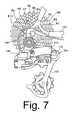
- rear sprocket assembly 99r comprises ten sprockets R1-R10 mounted coaxially with an axle 145 (Fig. 7) of rear wheel 106r.
- the number of teeth on front sprocket F1 is less than the number of teeth on front sprocket F2.
- the numbers of teeth on rear sprockets R1-R10 gradually decrease from rear sprocket R1 to rear sprocket R10.
- rear sprocket R1 has the greatest number of teeth
- rear sprocket R10 has the least number of teeth.
- Front derailleur 97f moves to two operating positions to switch chain 95 between front sprockets F1 and F2, and rear derailleur 97r moves to ten operating positions to switch chain 95 among selected ones of the rear sprockets R1-R10.
- a front gear position sensor 133f (Fig.
- a battery or some other power source powers front and rear derailleur 97f and 97r as well as other electrical components described herein in a known manner.
- rear derailleur 99r comprises a base member 140 that houses a gear shift motor and deceleration mechanism, a link mechanism 141 pivotably connected to base member 140, and a movable member 142 pivotably mounted to link mechanism 141 so that movable member 142 moves laterally relative to base member 140 in accordance with the operation of the motor housed within base member 140.
- Movable member 142 pivotably supports a chain guide 143 so that lateral movement of movable member 142 switches chain 95 among rear sprockets R1-R10.
- Handlebar assembly 104 comprises a handlebar stem 111 and a drop-style handlebar 112, wherein handlebar stem 111 is mounted to the upper part of fork 98, and handlebar 112 is mounted to the forward end portion of handlebar stem 111.
- brake lever assemblies 113f and 113r are mounted at opposite sides of handlebar 112.
- Brake lever assembly 113f controls the operation of front wheel brake 107f
- brake lever assembly 113r controls the operation of rear wheel brake 107r.
- a derailleur control device 110 is mounted to a central portion of handlebar 112.
- Brake lever assemblies 113f and 113r comprise respective brake brackets 115f and 115r mounted to the forward curved portions of handlebar 112, and brake levers 116f and 116r pivotably mounted to brake brackets 115f and 115r.
- Rear shift control devices 120r and 121r with switch levers 125 are mounted to the inner side of brake bracket 115r and to the rear side of brake lever 116r, respectively, to control the operation of rear derailleur 97r.
- rear shift control devices 120r and 121r independently control the operation of rear derailleur 97r so that the rider may control the operation of rear derailleur 97r with the hand grasping brake bracket 115r or with the hand grasping brake lever 116r. As shown in Fig.
- the switch lever 125 mounted to brake lever bracket 115r rotates downward from a home position P0 to a first position P1 and rotates upward from home position P0 to a second position P2 to control the operation of rear derailleur 97r.
- the switch lever 125 mounted to the rear of brake lever 116r rotates laterally inward from a home position P0 to a first position P1 and rotates laterally outward from home position P0 to a second position P2 to control the operation of rear derailleur 97r.
- independent front shift control devices 120f and 121f with switch levers 125 are mounted to the inner side of brake bracket 115f and to the rear side of brake lever 116f, respectively, to control the operation of front derailleur 97f.
- the switch levers 125 mounted to brake lever bracket 115f and brake lever 116f operate in the same manner as switch levers 125 mounted to brake lever bracket 115r and brake lever 116r. All of the switch levers 125 are biased toward the home position P0.
- a front upshift switch 131f (Fig. 6) and a front downshift switch 132f are mounted in each front shift control device 120f and 121f.
- the front upshift switches 131f operate when switch levers 125 in front shift control devices 120f and 121 f rotate from position P0 to position P1
- the front downshift switches 132f operate when switch levers 125 in front shift control devices 120f and 121f rotate from position P0 to position P2.
- a rear upshift switch 131r and a rear downshift switch 132r are mounted in each rear shift control device 120r and 121r.
- the rear upshift switches 131r operate when switch levers 125 in rear shift control devices 120r and 121r rotate from position P0 to position P1
- the rear downshift switches 132r operate when switch levers 125 in rear shift control devices 120r and 121r rotate from position P0 to position P2.
- many different switch combinations that operate in many different ways may be provided to suit different applications.
- derailleur control device 110 comprises a case 126 mounted onto the central portion of handlebar 112. Mounted within case 126 are a control unit 130, a liquid crystal display (LCD) 135 for displaying riding parameters and other information, a mode switch 136 and a set switch 137.
- a control unit 130 mounted within case 126 are a control unit 130, a liquid crystal display (LCD) 135 for displaying riding parameters and other information, a mode switch 136 and a set switch 137.
- Front derailleur 97f, rear derailleur 97r, front upshift switch 131 f, front downshift switch 132f, rear upshift switch 131r, rear downshift switch 132r, front gear position sensor 133f, rear gear position sensor 133r and other I/O units are connected to control unit 130 through appropriate methods such as wired or wireless devices.
- a storage unit such as a memory 138 stores various parameters used in the operation of control unit 130.
- a speed sensor 122 is mounted to fork 98 to sense the passage of a magnet 123 mounted to a spoke 106s of front wheel 106s and to provide speed indicating signals to control unit 130.
- control unit 130 comprises a programmed microprocessor.
- Control unit 130 includes a gear shift controller 130a, an adjustment controller 130b and an updating unit 130c.
- Gear shift controller 130a controls the operation of front derailleur 97f and rear derailleur 97r in a normal mode of operation such as a gear shift mode of operation (for example) to shift chain 95 the distance from an origin sprocket to a destination sprocket in accordance with signals received from front and rear upshift switches 131f and 131r, front and rear downshift switches 132f and 132r, and front and rear gear position sensors 133f and 133r.
- Adjustment controller 130b adjusts the positions of front derailleur 97f and rear derailleur 97r in an adjustment mode of operation to fine tune the stored operating positions of front derailleur 97f and rear derailleur 97r whenever the actual operating positions of the derailleurs vary from their proper operating positions, for example, or for some other reason.
- Updating unit 130c may be used to adjust all of the stored operating positions of front derailleur 97f and rear derailleur 97r based on the adjustment of the operating position of one sprocket. Of course, updating may be based on more than one sprocket, depending upon the application.
- Control unit 130 also displays speed, gear positions, and running distance on LCD 135 based on signals received from speed sensor 122 and gear position sensors 133f and 133r.
- Mode switch 136 is used to select the gear shift and adjustment modes of operation of control unit 130. Mode switch 136 also is used to alternate among the various display modes available to LCD 135. Set switch 137 is used to enter the mode selected by mode switch 136. Set switch 137 also is used to indicate the fact that adjustment has been completed in the adjustment mode.
- Fig. 9 is a flow chart of a particular embodiment of the operation of control unit 130.
- Initialization is carried out in a step S1 when power is supplied to control unit 130.
- various flags and variables are reset and operating positions (FP, RP) are set to predetermined values and stored in memory 138.
- the control mode is set by default to gear shift mode.
- step S2 display processing is performed.
- the speed and distance ridden are displayed on LCD 135 based on signals from speed sensor 133, and the sprocket positions of front and rear derailleurs 97f and 97r are displayed based on the output from front and rear gear position sensors 133f and 133r.
- the sprocket positions are displayed in both gear shift and adjustment modes.
- step S3 It is then determined in a step S3 whether or not a mode setting process is requested, typically by the operation of mode switch 136 and set switch 137. If so, then a mode setting process shown in Fig. 10 is performed in a step S 10. In any event, it is then determined in a step S4 whether or not gear shift mode is set. If so, then a conventional gear shift process is performed in a step S11.
- front derailleur 97f upshifts when a front upshift switch 131f is turned on as a result of a switch lever 125 in front shift control device 120f or 121 f rotating from position P0 to position P1
- rear derailleur 97r upshifts in single increments (i.e., one sprocket position at a time) when a rear upshift switch 131r is turned on as a result of a switch lever 125 in rear shift control device 120r or 121r rotating from position P0 to position P1
- rear derailleur 97r downshifts in single increments when a rear downshift switch 132r is turned on as a result of a switch lever 125 in rear shift control device 120r or 121r rotating from position P0 to position P2.
- step S5 it is then determined in a step S5 whether or not adjustment mode is set. If so, then an adjustment process shown in Fig. 11 is performed in a step S12. In any event, it is then determined in a step S6 whether other processes have been selected. If so, then such other processes are performed in a step S 13. The process then returns to step S2.
- Fig. 10 is a flow chart of a particular embodiment of the mode setting process performed in step S10 of Fig. 9.
- this mode setting process it is first determined in a step S21 whether or the mode switch 136 was turned on. If so, it is then determined in a step S24 whether or not control unit 130 currently is in gear shift mode. If so, then control unit 130 outputs a command to change to adjustment mode (adjustment mode command ON) in a step S25. Otherwise, control unit 130 outputs a command to change to gear shift mode (gear shift mode command ON) in a step S25.
- the net result is a command to switch to an operating mode opposite the current operating mode.
- step S22 it is then determined in a step S22 whether or not an adjustment mode command was output by control unit 130 (adjustment mode command ON). If so, it is then determined in a Step S27 whether or not set switch 137 is turned on. If so, then adjustment mode is set in a step S28. At that time, display of the gear shift mode in LCD 135 is switched off and display of the adjustment mode is switched on. Output of the adjustment mode command then stops to complete the mode change operation.
- step S223 it is then determined in a step S223 whether or not a gear shift mode command was output by control unit 130 (gear shift mode command ON). If so, it is then determined in a Step S29 whether or not set switch 137 is turned on. If so, then gear shift mode is set in a step S30. At that time, display of the adjustment mode in LCD 135 is switched off and display of the gear shift mode is switched on. Output of the gear shift mode command then stops to complete the mode change operation. The process returns to step S4 in Fig. 9 after completion of all of the above steps.
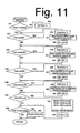
- Fig. 11 is a flow chart of a particular embodiment of the adjustment process performed in step S12 of Fig. 9.
- a timer Tc measures the time since the last operation of any one of the shift control devices 120f, 120r, 121f or 121r. If none of the shift control devices 120f, 120r, 121f or 121r is operated for a predetermined time period (e.g., 10-20 seconds) when control unit 130 is in adjustment mode, then the operating mode switches back to gear shift mode. If timer Tc has not yet started, then control unit 130 starts timer Tc in step S42.
- step S43 it is then determined in step S43 whether or not a front upshift switch 131f has been operated as a result of the operation front shift control device 120f or 121f. If so, then timer Tc is reset in a step S50, front derailleur 97f is moved in the upshift direction (laterally outward) by a small distance d1 (e.g., 0.1mm-0.3mm), and a variable SF that is incremented or decremented in response to the operation of front upshift switch 131f or front downshift switch 132f, respectively, is incremented by 1.
- d1 e.g., 0.1mm-0.3mm
- a front downshift switch 132f it is then determined in a step S44 whether or not a front downshift switch 132f has been operated as a result of the operation front shift control device 120f or 121 f. If so, then timer Tc is reset in a step S53, front derailleur 97f is moved in the downshift direction (laterally inward) by distance d1, and variable SF is decremented by 1. The relationship between the distance of movement of front derailleur 97f and the values output from front gear position sensor 133f is stored in advance in storage unit 138 and used for these operations.
- step S45 is then determined in step S45 whether or not a rear upshift switch 131r has been operated as a result of the operation front shift control device 120r or 121r. If so, then timer Tc is reset in a step S56, rear derailleur 97r is moved in the upshift direction (laterally outward) by a small distance d2 (e.g., 0.05mm-0.2mm), and a variable SR that is incremented or decremented in response to the operation of rear upshift switch 131r or rear downshift switch 132r, respectively, is incremented by 1.
- d2 e.g., 0.05mm-0.2mm
- step S46 it is then determined in a step S46 whether or not a rear downshift switch 132r has been operated as a result of the operation of rear shift control device 120r or 121 r. If so, then timer Tc is reset in a step S59, rear derailleur 97r is moved in the downshift direction (laterally inward) by distance d2, and variable SR is decremented by 1. The relationship between the distance of movement of rear derailleur 97r and the values output from rear gear position sensor 133r is stored in advance in storage unit 138 and used for these operations.
- step S47 is then determined in step S47 whether or not set switch 137 has been operated, thus signifying a request by the rider to complete the adjustment operation. If so, both front derailleur operating positions FP(1) and FP(2) are updated by adding an adjustment distance to the original operating positions FP(1) and FP(2), wherein the adjustment distance comprises the product of variable SF and distance d1 (SF x d1).
- the adjustment distance comprises the product of variable SF and distance d1 (SF x d1).
- all of the rear derailleur operating positions RP(1) - RP(10) are updated by adding an adjustment distance to the original operating positions RP(1) - RP(2), wherein the adjustment distance comprises the product of variable SR and distance d2 (SR x d2).
- the adjustment distance comprises the product of variable SR and distance d2 (SR x d2).
- step S48 it is then determined in step S48 whether or not timer Tc has completed its run, thus indicating that none of the shift control devices 120f, 121f, 120r and 121r has been operated for the predetermined. If so, then control unit 130 reverts to gear shift mode in a step S64. In other words, the system automatically returns to gear shift mode in case the rider forgets to manually return to gear shift mode. In any event, processing then returns to step S6 in Fig. 9.
- Fig. 12 is a flow chart of another embodiment of the operation of control unit 130.
- operating position adjustments were performed by changing the operating mode from a normal mode to an adjustment mode, but such adjustments may be performed using dedicated adjustment switches.
- shift control devices 121f and 121r may be used for gear shifting
- shift control devices 120f and 120r may be used for adjusting the operating positions of front and rear deraille 97f and 97r, respectively, in which case control devices 121 f and 121r may be considered to be adjustment control devices.
- separate dedicated adjustment control units may be used.
- step S71 initialization is carried out in a step S71. It is then determined in a step S72 whether or not a front upshift has been requested by the operation of shift control device 121f. If so, it is then determined in a step S81 whether or not front derailleur 97f is at the operating position for front sprocket F2. If so, then no further upshifting is possible, the upshift request is ignored, and processing continues in step S73. Otherwise, upshifting is performed in a step S82, and processing continues in step S73. It is then determined in step S73 whether or not a front downshift has been requested by the operation of shift control device 121f.
- step S83 it is then determined in a step S83 whether or not front derailleur 97f is at the operating position for front sprocket F1. If so, then no further downshifting is possible, the downshift request is ignored, and processing continues in step S74. Otherwise, downshifting is performed in a step S84, and processing continues in step S74.
- step S74 It is then determined in a step S74 whether or not a rear upshift has been requested by the operation of shift control device 121r. If so, it is then determined in a step S85 whether or not rear derailleur 97r is at the operating position for rear sprocket R10. If so, then no further upshifting is possible, the upshift request is ignored, and processing continues in step S75. Otherwise, upshifting is performed in a step S86, and processing continues in step S75. It is then determined in step S75 whether or not a rear downshift has been requested by the operation of shift control device 121 r. If so, it is then determined in a step S87 whether or not rear derailleur 97r is at the operating position for rear sprocket R1. If so, then no further downshifting is possible, the downshift request is ignored, and processing continues in step S76. Otherwise, downshifting is performed in a step S88, and processing continues in step S76.
- step S76 It is then determined in a step S76 whether or not adjustment of front derailleur 97f in the upshift direction has been requested by the operation of adjustment control device 120f. If so, then front derailleur 97f is moved in the upshift direction by the desired upshift adjustment distance (e.g., based on the length of time of operation of adjustment control device 120f) in a step S90, and the front operating positions FP are updated in a step S91 using the adjustment distance. It is then determined in a step S77 whether or not adjustment of front derailleur 97f in the downshift direction has been requested by the operation of adjustment control device 120f.
- the desired upshift adjustment distance e.g., based on the length of time of operation of adjustment control device 120f
- front derailleur 97f is moved in the downshift direction by the desired downshift adjustment distance in a step S92, and the front operating positions FP are updated in a step S93 using the adjustment distance. While all of the operating positions for front derailleur 97f may be updated in one step, it is possible to update the specific position being adjusted in one step and then adjust the remaining positions in a following step.
- step S78 It is then determined in a step S78 whether or not adjustment of rear derailleur 97r in the upshift direction has been requested by the operation of adjustment control device 120r. If so, then rear derailleur 97r is moved in the upshift direction by the desired upshift adjustment distance (e.g., based on the length of time of operation of adjustment control device 120r) in a step S94, and the rear operating positions RP are updated in a step S95 using the adjustment distance. It is then determined in a step S79 whether or not adjustment of rear derailleur 97r in the downshift direction has been requested by the operation of adjustment control device 120r.
- the desired upshift adjustment distance e.g., based on the length of time of operation of adjustment control device 120r
- rear derailleur 97r is moved in the downshift direction by the desired downshift adjustment distance in a step S96, and the rear operating positions RP are updated in a step S97 using the adjustment distance. While all of the operating positions for rear derailleur 97r may be updated in one step, it is possible to update the specific position being adjusted in one step and then adjust the remaining positions in a following step.
- Figs. 13 and 14 are flow charts of another embodiment of the operation of control unit 130.
- a step S99 is inserted between step S5 and step S6 in Fig. 9 to produce the flow chart shown in Fig. 13.
- step S99 it is determined whether or not the current mode is a gear position setting mode.
- the gear position setting mode may be set via the mode setting process shown in Fig. 10, for example.
- step S99 it is possible to have the gear shift mode, the adjustment mode, the gear position setting mode and any other available modes alternate in a cyclical fashion upon each operation of mode switch 136, and then set switch 137 may be operated set the desired mode. If it is determined in step S99 that gear position setting mode has been set, then a gear position setting process is performed in a step S100.
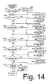
- Fig. 14 is a flow chart of a particular embodiment of the gear setting process of step S100.
- the number of front sprockets 99f is set by operating shift control device 120f or 121f
- the number of rear sprockets 99r is set by operating shift control device 120r or 121r. The number is increased when the corresponding shift control device is operated in the upshift direction, and the number is decreased when the corresponding shift control device is operated in the downshift direction.
- the proper numbers are selected, they are set using set switch 137, whereupon the operating positions for all of the sprockets are set automatically.
- Timer Td is used to revert control unit 130 to gear shift mode when none of the shift control devices 120f, 120r, 121f and 121r has been operated for a predetermined time period (e.g., 10-20 seconds) when control unit 130 is in the gear position setting mode. If timer Td has not yet started, then timer Td is started in a step S102. In any event, it is then determined in a step S103 whether or not front a upshift switch 131f has been operated by the operation of shift control device 120f or 121 f to increment the number of front sprockets.
- a timer Td is used to revert control unit 130 to gear shift mode when none of the shift control devices 120f, 120r, 121f and 121r has been operated for a predetermined time period (e.g. 10-20 seconds) when control unit 130 is in the gear position setting mode. If timer Td has not yet started, then timer Td is started in a step S102. In any event, it is then determined in
- timer Td is reset in a step S 110, and it is then determined in a step S111 whether or not a current cumulative total FN for the number of front sprockets is equal to 3. This determination is made to limit the maximum number of front sprockets to 3, since the number of front sprockets 99f in this embodiment is either 2 or 3. Thus, if FN is equal to 3, the request is ignored, and processing continues in step S104. If FN is not equal to 3, then FN is incremented by one in a step S 112.
- step S 104 it is then determined in a step S 104 whether or not a front downshift switch 132f has been operated by the operation of shift control device 120f or 121 f to decrement the number of front sprockets. If so, then timer Td is reset in a step S113, and it is then determined in a step S111 whether or not FN is equal to 2. This determination is made to limit the minimum number of front sprockets to 2. Thus, if FN is equal to 2, the request is ignored, and processing continues in step S105. If FN is not equal to 2, then FN is decremented by one in a step S 115.
- step S105 it is then determined in step S105 whether or not rear upshift switch 131r has been operated by the operation of shift control device 120r or 121r to increment the number of rear sprockets. If so, then timer Td is reset in a step S 116, and it is then determined in a step S117 whether or not a current cumulative total RN for the number of rear sprockets is equal to 10. This determination is made to limit the maximum number of rear sprockets to 10, since the normal number of rear sprockets 99r in this embodiment is from 7 to 10. Thus, if RN is equal to 10, the request is ignored, and processing continues in step S106.
- step S118 If RN is not equal to 10, then RN is incremented by one in a step S118. In any event, it is then determined in step S106 whether or not rear a downshift switch 132r has been operated by the operation of shift control device 120r or 121r to decrement the number of rear sprockets. If so, then timer Td is reset in a step S119, and it is then determined in a step S120 whether or not RN is equal to 7. This determination is made to limit the minimum number of rear sprockets to 7. Thus, if RN is equal to 7, the request is ignored, and processing continues in step S107. If RN is not equal to 7, then RN is decremented by one in a step S121.
- step S107 it is determined in step S107 whether or not set switch 137 has been operated. If so, then the operating positions FP(n) (where (n) is a positive integer from 1 to FN) of front derailleur 97f for the FN sprockets is updated to the operating positions FL (FN) stored in memory 138 for that number FN of sprockets 99f.
- the operating positions RP(m) (where (m) is a positive integer from 1 to RN) of rear derailleur 97r for the RN sprockets is updated to the operating positions RL (RN) stored in memory 138 for that number RN of rear sprockets 99r.
- step S108 it is then determined in step S108 whether or not timer Td has completed its run, thus indicating that none of the shift control devices 120f, 121 f, 120r and 121r has been operated for the predetermined time period. If so, then control unit 130 reverts to gear shift mode in a step S124. In other words, the system automatically returns to gear shift mode in case the rider forgets to manually return to gear shift mode. In any event, processing then returns to step S6 in Fig. 13.
- the operating mode was switched via operation of mode switch 136, but the operating mode may be switched using dedicated operating mode switches, one per operating mode.
- the adjustment distance was changed based on the number of times that a shift control device 120f, 120r, 121f or 121r was operated during adjustment mode processing, the adjustment distance may be changed based on the amount of time that the shift control device 120f, 120r, 121f or 121r operates.
- mode switching may be accomplished by operating one of the shift control devices 120f, 120r, 121f or 121r for a minimum predetermined time period (e.g., two seconds). While the described embodiments were applied to a road bicycle, the bicycle may have any configuration.
Landscapes
- Engineering & Computer Science (AREA)
- Chemical & Material Sciences (AREA)
- Combustion & Propulsion (AREA)
- Transportation (AREA)
- Mechanical Engineering (AREA)
- Control Of Transmission Device (AREA)
- Axle Suspensions And Sidecars For Cycles (AREA)
Abstract
Description
Claims (24)
- An apparatus for adjusting positions of a bicycle control device that moves to a plurality of operating positions (FP, RP), wherein the apparatus comprises:wherein the updating unit (130c) provides a first updated operating position value from a first operating position value from the plurality of operating position values based on the adjustment value; anda memory that stores a plurality of operating position values corresponding to the plurality of operating positions (FP, RP);an adjustment value providing unit (130b) that provides an adjustment value; andan updating unit (130c);
wherein the updating unit (130c) provides a second updated operating position value from a different second operating position value from the plurality of operating position values based on the adjustment value. - The apparatus according to claim 1 wherein the adjustment value is not one of the plurality of operating position values.
- The apparatus according to claim 1 wherein the plurality of operating position values correspond to a plurality of derailleur positions.
- The apparatus according to claim 1 wherein the updating unit (130c) stores the first updated operating position value and the second updated operating position value in the memory (138).
- The apparatus according to claim 1 wherein the updating unit (130c) provides updated operating position values for all of the plurality of operating position values based on the adjustment value used to provide the first updated operating position value.
- The apparatus according to claim 5 wherein the updating unit (130c) stores all of the updated operating position values in the memory (138).
- The apparatus according to claim 1 wherein the adjustment value providing unit (130b) comprises a position setting unit for the bicycle control device.
- The apparatus according to claim 7 wherein the adjustment value providing unit (130b) is mounted to a brake lever assembly (113f, 113r).
- The apparatus according to claim 7 wherein the adjustment value comprises an adjustment movement value.
- The apparatus according to claim 7 wherein the adjustment value providing unit (130b) comprises a manually operated electrical switch (131f, 131r, 132f, 132r).
- The apparatus according to claim 10 wherein the adjustment value comprises an adjustment movement value, and wherein the adjustment value is incremented upon operation of the switch (131f, 131r, 132f, 132r).
- The apparatus according to claim 11 wherein the adjustment value is incremented upon each of a plurality of operations of the switch (131f, 131 r, 132f, 132r).
- The apparatus according to claim 11 wherein the adjustment value is incremented based on a length of a time period of operation of the switch (131f, 131r, 132f, 132r).
- The apparatus according to claim 11 wherein the plurality of operating position values correspond to a plurality of derailleur positions, and wherein the adjustment movement value corresponds to an adjustment movement of the derailleur (97f, 97r).
- The apparatus according to claim 14 further comprising:wherein the gear shift controller moves the derailleur (97f, 97r) to one of the plurality of operating position (FP, RP) in an upshift direction in response to operation of the upshift switch (131f, 131r); andat least one of an upshift switch (131f, 131r) and a downshift switch (132f, 132r) for the derailleur (97f, 97r); anda gear shift controller;
wherein the gear shift controller moves the derailleur (97f, 97r) to one of the plurality of operating position (FP, RP) in a downshift direction in response to operation of the downshift switch (132f, 132r). - The apparatus according to claim 14 wherein the switch (131f, 131r, 132f, 132r) comprises
an operating member (125);
an upshift switch (131f, 131r); and
a downshift switch (132f, 132r);
wherein the operating member (125) moves from a neutral position to an upshift position to operate the upshift switch (131f, 131r); and
wherein the operating member (125) moves from the neutral position to a downshift position to operate the downshift switch (132f, 132r). - The apparatus according to claim 16 wherein the adjustment movement value corresponds to an adjustment movement of the derailleur (97f, 97r) in an upshift direction when the switch (131 f, 131r, 132f, 132r) moves from the neutral position to the upshift position, and wherein the adjustment movement value corresponds to an adjustment movement of the derailleur (97f, 97r) in a downshift direction when the switch (131f, 131r, 132f, 132r) moves from the neutral position to the downshift position.
- The apparatus according to claim 1 further comprising an operating mode setting unit, wherein the operating mode setting unit sets the apparatus into a normal mode in which the bicycle control device is controlled to move to selected ones of the plurality of operating position (FP, RP), and wherein the operating mode setting unit sets the apparatus into an adjustment mode in which the bicycle control device is controlled to move a distance less than a distance between first and second operating position (FP, RP).
- The apparatus according to claim 18 wherein the plurality of values correspond to a plurality of derailleur positions, wherein the adjustment value providing unit (130b) further comprises at least one of an upshift switch (131f, 131r) and a downshift switch (132f, 132r) for a derailleur (97f, 97r), and further comprising:wherein, when the apparatus is in the normal mode:a gear shift controller(130a); andan adjustment controller (130b);wherein, when the apparatus is in the adjustment mode:the gear shift controller(130a) moves the derailleur (97f, 97r) to one of the plurality of derailleur positions in an upshift direction in response to operation of the upshift switch (131f, 131 r); andthe gear shift controller(130a) moves the derailleur (97f, 97r) to one of the plurality of derailleur positions in a downshift direction in response to operation of the downshift switch (132f, 132r); andthe adjustment controller (130b) moves the derailleur (97f, 97r) an adjustment distance in an upshift direction in response to operation of the upshift switch (131 f, 131r); andthe adjustment controller (130b) moves the derailleur (97f, 97r) an adjustment distance in a downshift direction in response to operation of the downshift switch (132f, 132r).
- The apparatus according to claim 19 wherein, when the at least one of the upshift switch (131f, 131r) and the downshift switch (132f, 132r) is operated for a first time interval, the operating mode setting unit switches the apparatus from one of the normal mode and the adjustment mode to the other one of the normal mode and the adjustment mode.
- The apparatus according to claim 20 wherein the operating mode setting unit sets the apparatus to the normal mode when the at least one of the upshift switch (131f, 131r) and the downshift switch (132f, 132r) is not operated during a second time interval.
- The apparatus according to claim 19 wherein the operating mode setting unit comprises a mode switch (136) separate from the at least one of the upshift switch (131f, 131r) and the downshift switch (132f, 132r) to set the apparatus to the normal mode and to the adjustment mode.
- The apparatus according to claim 22 wherein the operating mode setting unit sets the apparatus to the normal mode when the mode switch is not operated during a time interval.
- The apparatus according to claim 1 further comprising:wherein the updating unit (130c) stores in the memory (138) an operating position value for each of the plurality of operating positions in response to the number indicating unit.a number indicating unit that indicates a number of the plurality of operating position (FP, RP); and
Applications Claiming Priority (2)
| Application Number | Priority Date | Filing Date | Title |
|---|---|---|---|
| JP2004094532A JP2005280408A (en) | 2004-03-29 | 2004-03-29 | Derailler control device for bicycle and control method |
| JP2004094532 | 2004-03-29 |
Publications (3)
| Publication Number | Publication Date |
|---|---|
| EP1582453A2 true EP1582453A2 (en) | 2005-10-05 |
| EP1582453A3 EP1582453A3 (en) | 2008-07-09 |
| EP1582453B1 EP1582453B1 (en) | 2016-11-09 |
Family
ID=34879903
Family Applications (1)
| Application Number | Title | Priority Date | Filing Date |
|---|---|---|---|
| EP05006795.8A Revoked EP1582453B1 (en) | 2004-03-29 | 2005-03-29 | Apparatus for adjusting a position of a bicycle control device |
Country Status (5)
| Country | Link |
|---|---|
| US (1) | US7547263B2 (en) |
| EP (1) | EP1582453B1 (en) |
| JP (1) | JP2005280408A (en) |
| CN (1) | CN100540390C (en) |
| TW (1) | TWI248410B (en) |
Cited By (2)
| Publication number | Priority date | Publication date | Assignee | Title |
|---|---|---|---|---|
| EP2093141A1 (en) * | 2008-02-20 | 2009-08-26 | Shimano Inc. | Bicycle component calibration device |
| CN104097739A (en) * | 2013-04-05 | 2014-10-15 | 株式会社岛野 | Bicycle derailleur adjusting apparatus |
Families Citing this family (28)
| Publication number | Priority date | Publication date | Assignee | Title |
|---|---|---|---|---|
| US7503547B2 (en) * | 2006-10-04 | 2009-03-17 | Shimano Inc. | Bicycle electric cable tensioning assembly |
| JP5783723B2 (en) * | 2007-12-21 | 2015-09-24 | フォールブルック インテレクチュアル プロパティー カンパニー エルエルシー | Automatic transmission and method thereof |
| JP2012179975A (en) * | 2011-02-28 | 2012-09-20 | Shimano Inc | Setting device of suspension control device for bicycle and suspension control device for bicycle |
| US9394030B2 (en) * | 2012-09-27 | 2016-07-19 | Sram, Llc | Rear derailleur |
| US9555856B2 (en) | 2013-03-25 | 2017-01-31 | Shimano Inc. | Electric front derailleur |
| US9005059B2 (en) * | 2013-03-27 | 2015-04-14 | Shimano Inc. | Rear derailleur |
| US9676444B2 (en) * | 2013-10-23 | 2017-06-13 | Sram, Llc | Electromechanical rear derailleur |
| US9199690B2 (en) * | 2013-12-27 | 2015-12-01 | Shimano Inc. | Bicycle suspension system |
| US9278728B1 (en) * | 2014-10-29 | 2016-03-08 | Shimano Inc. | Bicycle shifting control apparatus and method of controlling derailleur |
| US20160236750A1 (en) * | 2015-02-13 | 2016-08-18 | Shimano Inc. | Bicycle drive system |
| US11801913B2 (en) | 2015-03-05 | 2023-10-31 | Shimano Inc. | Bicycle electric component setting system |
| US20170066501A1 (en) * | 2015-09-08 | 2017-03-09 | Praxis Works LLC | Belt-aligned derailleur |
| US9656723B1 (en) * | 2015-12-14 | 2017-05-23 | Shimano Inc. | Electrical bicycle derailleur |
| US9714067B1 (en) * | 2016-02-29 | 2017-07-25 | Shimano Inc. | Bicycle chain device |
| TWI648198B (en) * | 2016-08-10 | 2019-01-21 | 天心工業股份有限公司 | Bicycle and its shifting device |
| TWI634043B (en) * | 2017-03-03 | 2018-09-01 | 台灣微轉股份有限公司 | Bicycle tuning system that can be easily adjusted |
| US10442497B2 (en) | 2017-04-25 | 2019-10-15 | Ad-Ii Engineering Inc. | Easy-adjustment bicycle gear-shifting system |
| US10745081B2 (en) * | 2017-07-28 | 2020-08-18 | Shimano Inc. | Bicycle rear derailleur and bicycle shifting control apparatus |
| TWM562815U (en) * | 2018-04-03 | 2018-07-01 | 彥豪金屬工業股份有限公司 | Derailleur assembly |
| TWM562816U (en) * | 2018-04-03 | 2018-07-01 | 彥豪金屬工業股份有限公司 | Derailleur assembly |
| DE102018207493A1 (en) * | 2018-05-15 | 2019-11-21 | Sram Deutschland Gmbh | A bicycle adjusting device and method of controlling or adjusting such adjusting devices |
| DE102018133082A1 (en) | 2018-12-20 | 2020-06-25 | Shimano Inc. | Control unit |
| US11498643B2 (en) * | 2019-02-26 | 2022-11-15 | Shimano Inc. | Bicycle electric derailleur |
| US10640171B2 (en) * | 2019-03-25 | 2020-05-05 | Hazem Nihad Hamed | Automatic bicycle shifter and user interface |
| TWI704083B (en) * | 2019-04-12 | 2020-09-11 | 彥豪金屬工業股份有限公司 | Bicycle derailleur adjusting method |
| TWI712547B (en) * | 2019-11-06 | 2020-12-11 | 天心工業股份有限公司 | Rear derailleur |
| TWI712540B (en) * | 2019-12-02 | 2020-12-11 | 彥豪金屬工業股份有限公司 | Derailleur position setting system and method thereof |
| US11981398B2 (en) * | 2020-09-11 | 2024-05-14 | Shimano Inc. | Bicycle derailleur |
Citations (1)
| Publication number | Priority date | Publication date | Assignee | Title |
|---|---|---|---|---|
| US5059158A (en) | 1990-05-08 | 1991-10-22 | E.B.T., Inc. | Electronic transmission control system for a bicycle |
Family Cites Families (14)
| Publication number | Priority date | Publication date | Assignee | Title |
|---|---|---|---|---|
| US4490127A (en) * | 1981-05-29 | 1984-12-25 | Sanyo Electric Co., Ltd. | Electrically operated transmission gear system for bicycles |
| DE3629808A1 (en) * | 1986-09-02 | 1988-03-10 | Keiper Dynafit | BICYCLE ERGOMETER |
| US5213548A (en) * | 1992-03-02 | 1993-05-25 | Colbert Ralph G | Gear shifting system for derailleur equipped bicycle |
| DE4212320A1 (en) * | 1992-04-13 | 1993-10-14 | Fichtel & Sachs Ag | Electric actuator |
| DE4212319A1 (en) * | 1992-04-13 | 1993-10-14 | Fichtel & Sachs Ag | control device |
| JP3470820B2 (en) * | 1993-10-06 | 2003-11-25 | 株式会社シマノ | Bicycle transmission |
| IT1276417B1 (en) * | 1995-06-07 | 1997-10-31 | Campagnolo Srl | "SPEED CHANGE DEVICE FOR BICYCLES WITH ELECTRONIC CONTROL" |
| US5599244A (en) * | 1995-08-14 | 1997-02-04 | Ethington; Russell A. | Automatic transmission shifter for velocipedes |
| JPH09315375A (en) * | 1996-05-30 | 1997-12-09 | Akebono Brake Ind Co Ltd | Speed change gear for bicycle |
| US6047230A (en) * | 1997-02-27 | 2000-04-04 | Spencer; Marc D. | Automatic bicycle transmission |
| US6367833B1 (en) * | 2000-09-13 | 2002-04-09 | Shimano, Inc. | Automatic shifting control device for a bicycle |
| JP4221641B2 (en) * | 2002-04-09 | 2009-02-12 | ソニー株式会社 | Data processing method, data processing method program, and recording medium storing data processing method program |
| ATE353814T1 (en) * | 2002-12-06 | 2007-03-15 | Campagnolo Srl | ELECTRONIC, SERVO OPERATED BICYCLE GEARSHIFT AND ASSOCIATED METHOD |
| DE60302782T2 (en) * | 2003-07-24 | 2006-07-13 | Campagnolo S.R.L. | Method for shifting a bicycle transmission with electric auxiliary drive and switching device |
-
2004
- 2004-03-29 JP JP2004094532A patent/JP2005280408A/en active Pending
- 2004-12-28 TW TW093141008A patent/TWI248410B/en not_active IP Right Cessation
-
2005
- 2005-01-21 CN CNB2005100026619A patent/CN100540390C/en not_active Expired - Lifetime
- 2005-03-22 US US10/907,135 patent/US7547263B2/en active Active
- 2005-03-29 EP EP05006795.8A patent/EP1582453B1/en not_active Revoked
Patent Citations (1)
| Publication number | Priority date | Publication date | Assignee | Title |
|---|---|---|---|---|
| US5059158A (en) | 1990-05-08 | 1991-10-22 | E.B.T., Inc. | Electronic transmission control system for a bicycle |
Cited By (4)
| Publication number | Priority date | Publication date | Assignee | Title |
|---|---|---|---|---|
| EP2093141A1 (en) * | 2008-02-20 | 2009-08-26 | Shimano Inc. | Bicycle component calibration device |
| US7805268B2 (en) | 2008-02-20 | 2010-09-28 | Shimano Inc. | Bicycle component calibration device |
| CN101513919B (en) * | 2008-02-20 | 2012-01-11 | 株式会社岛野 | Bicycle component calibration device |
| CN104097739A (en) * | 2013-04-05 | 2014-10-15 | 株式会社岛野 | Bicycle derailleur adjusting apparatus |
Also Published As
| Publication number | Publication date |
|---|---|
| US20050215369A1 (en) | 2005-09-29 |
| EP1582453A3 (en) | 2008-07-09 |
| TWI248410B (en) | 2006-02-01 |
| US7547263B2 (en) | 2009-06-16 |
| TW200531877A (en) | 2005-10-01 |
| CN100540390C (en) | 2009-09-16 |
| EP1582453B1 (en) | 2016-11-09 |
| JP2005280408A (en) | 2005-10-13 |
| CN1676414A (en) | 2005-10-05 |
Similar Documents
| Publication | Publication Date | Title |
|---|---|---|
| EP1582453B1 (en) | Apparatus for adjusting a position of a bicycle control device | |
| EP1584552B1 (en) | Switch designation apparatus for a bicycle control unit | |
| EP1584551B1 (en) | Bicycle derailleur control device and method for controlling a front derailleur | |
| EP2383178B1 (en) | Bicycle rear derailleur | |
| EP1591355B1 (en) | Apparatus for controlling a bicycle gear shift device based on movement of the device | |
| EP1693295B1 (en) | Bicycle gear shifting control apparatus | |
| JP4950236B2 (en) | Bicycle component position correction device | |
| TWI548557B (en) | Bicycle gear changing apparatus | |
| EP3196109B1 (en) | Bicycles with electronic shifting systems and methods | |
| EP1925547B1 (en) | Derailleur control device and method for controlling the front derailleur | |
| US6467786B2 (en) | Automatic shifting control device for a bicycle | |
| US10336400B2 (en) | Bicycle transmission control apparatus | |
| US20120245809A1 (en) | Method and apparatus for shifting a bicycle transmission | |
| US6722220B2 (en) | Override control for a bicycle transmission | |
| EP1304287B1 (en) | Method and apparatus for controlling a bicycle transmission |
Legal Events
| Date | Code | Title | Description |
|---|---|---|---|
| PUAI | Public reference made under article 153(3) epc to a published international application that has entered the european phase |
Free format text: ORIGINAL CODE: 0009012 |
|
| AK | Designated contracting states |
Kind code of ref document: A2 Designated state(s): AT BE BG CH CY CZ DE DK EE ES FI FR GB GR HU IE IS IT LI LT LU MC NL PL PT RO SE SI SK TR |
|
| AX | Request for extension of the european patent |
Extension state: AL BA HR LV MK YU |
|
| RAP1 | Party data changed (applicant data changed or rights of an application transferred) |
Owner name: SHIMANO INC. |
|
| PUAL | Search report despatched |
Free format text: ORIGINAL CODE: 0009013 |
|
| AK | Designated contracting states |
Kind code of ref document: A3 Designated state(s): AT BE BG CH CY CZ DE DK EE ES FI FR GB GR HU IE IS IT LI LT LU MC NL PL PT RO SE SI SK TR |
|
| AX | Request for extension of the european patent |
Extension state: AL BA HR LV MK YU |
|
| 17P | Request for examination filed |
Effective date: 20080808 |
|
| AKX | Designation fees paid |
Designated state(s): DE FR IT NL |
|
| 17Q | First examination report despatched |
Effective date: 20101117 |
|
| GRAP | Despatch of communication of intention to grant a patent |
Free format text: ORIGINAL CODE: EPIDOSNIGR1 |
|
| INTG | Intention to grant announced |
Effective date: 20160805 |
|
| GRAS | Grant fee paid |
Free format text: ORIGINAL CODE: EPIDOSNIGR3 |
|
| GRAA | (expected) grant |
Free format text: ORIGINAL CODE: 0009210 |
|
| AK | Designated contracting states |
Kind code of ref document: B1 Designated state(s): DE FR IT NL |
|
| REG | Reference to a national code |
Ref country code: DE Ref legal event code: R096 Ref document number: 602005050630 Country of ref document: DE |
|
| REG | Reference to a national code |
Ref country code: NL Ref legal event code: MP Effective date: 20161109 |
|
| PG25 | Lapsed in a contracting state [announced via postgrant information from national office to epo] |
Ref country code: NL Free format text: LAPSE BECAUSE OF FAILURE TO SUBMIT A TRANSLATION OF THE DESCRIPTION OR TO PAY THE FEE WITHIN THE PRESCRIBED TIME-LIMIT Effective date: 20161109 |
|
| REG | Reference to a national code |
Ref country code: DE Ref legal event code: R026 Ref document number: 602005050630 Country of ref document: DE |
|
| PLBI | Opposition filed |
Free format text: ORIGINAL CODE: 0009260 |
|
| PGFP | Annual fee paid to national office [announced via postgrant information from national office to epo] |
Ref country code: IT Payment date: 20170323 Year of fee payment: 13 |
|
| PLAX | Notice of opposition and request to file observation + time limit sent |
Free format text: ORIGINAL CODE: EPIDOSNOBS2 |
|
| 26 | Opposition filed |
Opponent name: SRAM, LLC Effective date: 20170809 |
|
| REG | Reference to a national code |
Ref country code: FR Ref legal event code: ST Effective date: 20171130 |
|
| PLBB | Reply of patent proprietor to notice(s) of opposition received |
Free format text: ORIGINAL CODE: EPIDOSNOBS3 |
|
| PG25 | Lapsed in a contracting state [announced via postgrant information from national office to epo] |
Ref country code: FR Free format text: LAPSE BECAUSE OF NON-PAYMENT OF DUE FEES Effective date: 20170331 |
|
| PG25 | Lapsed in a contracting state [announced via postgrant information from national office to epo] |
Ref country code: IT Free format text: LAPSE BECAUSE OF NON-PAYMENT OF DUE FEES Effective date: 20180329 |
|
| APAH | Appeal reference modified |
Free format text: ORIGINAL CODE: EPIDOSCREFNO |
|
| APBM | Appeal reference recorded |
Free format text: ORIGINAL CODE: EPIDOSNREFNO |
|
| APBP | Date of receipt of notice of appeal recorded |
Free format text: ORIGINAL CODE: EPIDOSNNOA2O |
|
| APBM | Appeal reference recorded |
Free format text: ORIGINAL CODE: EPIDOSNREFNO |
|
| APBP | Date of receipt of notice of appeal recorded |
Free format text: ORIGINAL CODE: EPIDOSNNOA2O |
|
| APBQ | Date of receipt of statement of grounds of appeal recorded |
Free format text: ORIGINAL CODE: EPIDOSNNOA3O |
|
| APAY | Date of receipt of notice of appeal deleted |
Free format text: ORIGINAL CODE: EPIDOSDNOA2O |
|
| PLAB | Opposition data, opponent's data or that of the opponent's representative modified |
Free format text: ORIGINAL CODE: 0009299OPPO |
|
| R26 | Opposition filed (corrected) |
Opponent name: SRAM, LLC Effective date: 20170809 |
|
| PGFP | Annual fee paid to national office [announced via postgrant information from national office to epo] |
Ref country code: DE Payment date: 20220620 Year of fee payment: 19 |
|
| P01 | Opt-out of the competence of the unified patent court (upc) registered |
Effective date: 20230428 |
|
| REG | Reference to a national code |
Ref country code: DE Ref legal event code: R103 Ref document number: 602005050630 Country of ref document: DE Ref country code: DE Ref legal event code: R064 Ref document number: 602005050630 Country of ref document: DE |
|
| APBU | Appeal procedure closed |
Free format text: ORIGINAL CODE: EPIDOSNNOA9O |
|
| RDAF | Communication despatched that patent is revoked |
Free format text: ORIGINAL CODE: EPIDOSNREV1 |
|
| RDAG | Patent revoked |
Free format text: ORIGINAL CODE: 0009271 |
|
| STAA | Information on the status of an ep patent application or granted ep patent |
Free format text: STATUS: PATENT REVOKED |
|
| 27W | Patent revoked |
Effective date: 20230711 |