EP1582425B1 - Method of wiping a windshield of a vehicle and windshield wiping device - Google Patents
Method of wiping a windshield of a vehicle and windshield wiping device Download PDFInfo
- Publication number
- EP1582425B1 EP1582425B1 EP04008014A EP04008014A EP1582425B1 EP 1582425 B1 EP1582425 B1 EP 1582425B1 EP 04008014 A EP04008014 A EP 04008014A EP 04008014 A EP04008014 A EP 04008014A EP 1582425 B1 EP1582425 B1 EP 1582425B1
- Authority
- EP
- European Patent Office
- Prior art keywords
- windshield
- glass
- wiper
- wiping
- wiper blade
- Prior art date
- Legal status (The legal status is an assumption and is not a legal conclusion. Google has not performed a legal analysis and makes no representation as to the accuracy of the status listed.)
- Expired - Lifetime
Links
- 238000000034 method Methods 0.000 title claims description 14
- 230000033001 locomotion Effects 0.000 claims abstract description 34
- 230000008878 coupling Effects 0.000 claims description 3
- 238000010168 coupling process Methods 0.000 claims description 3
- 238000005859 coupling reaction Methods 0.000 claims description 3
- 239000011521 glass Substances 0.000 claims 29
- 230000005540 biological transmission Effects 0.000 claims 1
- XLYOFNOQVPJJNP-UHFFFAOYSA-N water Substances O XLYOFNOQVPJJNP-UHFFFAOYSA-N 0.000 description 5
- 230000015572 biosynthetic process Effects 0.000 description 3
- 230000000284 resting effect Effects 0.000 description 2
- 238000011161 development Methods 0.000 description 1
- 230000018109 developmental process Effects 0.000 description 1
- 230000000694 effects Effects 0.000 description 1
- 239000012535 impurity Substances 0.000 description 1
- 125000006850 spacer group Chemical group 0.000 description 1
Images
Classifications
-
- B—PERFORMING OPERATIONS; TRANSPORTING
- B60—VEHICLES IN GENERAL
- B60S—SERVICING, CLEANING, REPAIRING, SUPPORTING, LIFTING, OR MANOEUVRING OF VEHICLES, NOT OTHERWISE PROVIDED FOR
- B60S1/00—Cleaning of vehicles
- B60S1/02—Cleaning windscreens, windows or optical devices
- B60S1/04—Wipers or the like, e.g. scrapers
- B60S1/32—Wipers or the like, e.g. scrapers characterised by constructional features of wiper blade arms or blades
- B60S1/34—Wiper arms; Mountings therefor
- B60S1/3411—Wiper arms; Mountings therefor with means for varying wiper-blade pressure on windshield during operation
Definitions
- Windscreen wiper devices for motor vehicles are known in principle. They serve to remove water and impurities from windows of a motor vehicle and frequently have one or more wiper arms with wiper blades held thereon and a drive for moving the wiper arms between two end positions. During the movement of the wiper arms between the two end positions, there is often the problem that, when the wiper blades move from one end position to the other end position, water can be removed from the disc essentially completely streak-free or completely, but that movement is reversed Direction of stripes or Wasserbeläge remain on the disc, which can affect the driver's view.
- DE 14 80 726 A discloses a method for automatic windscreen wiping for a windscreen of a motor vehicle according to the preamble of claim 1 and a device for wiping a windscreen of a motor vehicle according to the preamble of claim 6.
- the present invention has for its object to provide a method for wiping a disc of a motor vehicle, which at high speeds, a wiping of the disc substantially without the formation of streaks, as well as to provide a corresponding windshield wiper device for wiping a window of a motor vehicle.
- the object is achieved by a method for wiping a window of a motor vehicle with the features of claim 1.
- At least one wiper blade is moved back and forth between a first and a second end position, wherein a wiper lip of the wiper blade continuously rests on the window during movement from the first to the second end position, while the entire But not in the opposite direction.
- the speed of the motor vehicle is detected and during wiping, the wiper lip is removed from the disc only when the speed is within a predetermined interval.
- the windshield wiper device has a control device for controlling the wiper blade adjustment device, to which a signal indicative of a speed of the motor vehicle can be fed, and by means of which the wiper blade adjustment device can be controlled such that removal of the wiper lip during wiping from the disc takes place only when the speed is within a predetermined interval.
- the end positions of the wiper blade result from the Wischerarmendlagen and the geometry of the wiper arm.
- the first and the second end position or Wischerarmendlage are chosen so that during a forward drive of the motor vehicle and at least half of Movement path of the wiper blade, the movement of the wiper lip resting on the disc has a running in the direction of the wind wind component. In this way it can be avoided that wiper water is pressed by the airstream between the wiper lip and the window, which could lead to a streaking or water deposit formation.
- the wiper lip can be brought in different ways with the disc in contact or removed from it.
- the wiper blade is rotated or pivoted about an axis oriented substantially parallel to a longitudinal axis of the wiper blade in order to bring the wiper lip into contact with the disk or to move it away from the disk.
- the wiper blade adjusting device comprises a rotating or pivoting device, by means of which the wiper arm and / or the wiper blade is rotatable or pivotable about an axis oriented substantially parallel to a longitudinal axis of the wiper blade to the wiper lip in To bring contact with the disc or to move it away from the disc.
- the axis about which the wiper blade is rotated or pivoted, depending on the structure of the wiper blade relative to the longitudinal axis of the wiper blade may be inclined by a few degrees, but preferably runs parallel thereto. In this embodiment act on the wiper arm and its bearing only very low forces.
- the rotation or pivoting of the wiper arm and / or the wiper blade can take place via a corresponding gear and the drive for moving the wiper arm.
- the wiper blade or the wiper arm may further comprise spacers, such as wheels, to keep the wiper arm and the wiper blade spaced from the disk when the wiper lip does not rest on the disk.
- the wiper blade is lowered or raised relative to the surface of the disc to bring the wiper lip into contact with the disc or lift it from the disc.
- the wiper blade adjusting device is designed such that the wiper arm can be lowered or raised relative to the surface of the windshield in order to bring the wiper lip into contact with the windshield or lift it off the windshield. This variant of the method allows a particularly simple design of the wiper blade adjusting device.
- the wiper blade adjusting device comprises surfaces by means of which the wiper arm can be raised away from the surface of the windshield by the aerodynamic effects of wind.
- no additional mechanical drive means are necessary.
- the wiper blade adjusting device comprises a runner, which is held pivotably on the wiper arm parallel to the direction of movement of the wiper blade between two rotor end layers and runs on the disk or a guide, and in that the wiper arm and / or the rotor are designed such that the wiper lip rests on the disc when the runner occupies the one runner end position, and the disc is not touched when the runner occupies the other runner end position.
- This can be achieved, in particular, by virtue of the fact that the rotor in the rotor end layers each has a different pivot angle with respect to a normal to the disk.
- the rotor end layers can be given in particular by simple, integrated in the wiper arm stops.
- the guide in this case, at the rotor end positions corresponding sections on devices in which the rotor is temporarily held in motion reversal, so that the rotor is brought from one rotor end position in the other rotor end position.
- the wiper arm can be raised or lowered by means of a coupling gear connected to a drive of the windscreen wiper device and the wiper arm.
- the coupling gear may have a corresponding shaft or disc with a cam, by means of which the wiper arm can be raised.
- the wiper blade adjusting device comprises an electric drive, by means of which the wiper arm and / or the wiper blade is adjustable.
- the predetermined interval for speeds within which the wiper lip is removed from the disc may be selected so that removal of the wiper lip from the disc occurs only at high speeds.
- the wiper arm can be moved back and forth in any desired manner between the end positions. However, it is preferred that the wiper blade is pivoted back and forth between the end positions. In the windshield wiper device, it is preferable that the wiper arm is swingable back and forth between its wiper arm end positions. In this way, a large area can be wiped on a disk with the least possible mechanical effort.
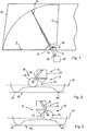
- a disc 10 of a motor vehicle and a windshield wiper device for wiping the disc 10 according to a first preferred embodiment of the invention is partially shown.
- the windshield wiper device comprises two identically formed, synchronously moved wiper arms with wiper blades held thereon, of which only the wiper arm 12 with a wiper blade 14 held thereon is shown in FIG. 1, and a drive 15 shown only very schematically in FIG. 1, by means of which Wiper arms between respective Wischarmendlagen and accordingly the wiper blades between respective end positions are back and forth.
- Fig. 1 only the first end position B and the second end position C of the wiper blade 14 are shown.
- the windscreen wiper device further comprises a guide 16 for a runner 18 held on the wiper arm 12.
- the drive 15 drives the wiper arms via drive shafts, of which in Fig. 1, only the drive shaft 20 is shown.
- the wiper arms are pivotally mounted in a conventional manner to the drive shafts in a corresponding plane through the respective longitudinal axis of the drive shaft 16 and are pressed by elastic elements, not shown in Fig. 1 in the direction of the disc 10.
- the rotor 18 is held on the wiper arm 12, which is pivotable about an axis extending parallel to a longitudinal axis of the wiper arm 12 and thus of the wiper blade 14.
- the rotor has a pivotally held on the wiper arm 12, U-shaped holder 24, between the free ends of a rotor wheel 26 is rotatably mounted.
- the impeller 26 moves in the groove-like guide 16.
- the wiper arm 12 in the region of the rotor 18 on an asymmetrical U-shaped profile 27, which limits pivotal movements of the rotor 18 with the respective free legs between two rotor end layers. Due to the asymmetrical design is achieved that the rotor 18 when pivoting in the two possible pivoting directions can achieve different maximum pivot angle with respect to a normal to the disc 10. For example, in Figs. 2 and 3, the slider 18 is pivotable leftward at a greater angle to the side than to the right, as it strikes the free ends of the asymmetrical U-shaped profile 27, respectively.
- the asymmetrical, U-shaped profile 27 of the wiper arm 12 in the region of the rotor 18, the length of the free legs of the U-shaped holder 24, the diameter of the rotor wheel 16 and the distance of the wiper arm 12 of the guide 16 are selected so that at a movement of the wiper blade 14 from the end position B in the end position C or a corresponding movement of the wiper arm 14, the impeller 26 is pressed only by the weight of the rotor 18 on the guide 16, so that the wiper blade 14 with the normal contact pressure with its wiper lip 22 rests on the disc 10.
- the impeller 26 Upon reaching the end position C, the impeller 26 remains in the right recess 28 'of the guide 16 hang so that it turns after movement of the wiper blade 14 from the second end position C in the direction of the first end position B, thereby to the corresponding portion of the U-shaped Profile 27 of the wiper arm 12 abuts, the second rotor end position occupies and so the wiper arm 12 with the wiper blade 14 lifts so far that the wiper lip 22 of the wiper blade 14 is thereby lifted from the disc 10 (see Fig .. 3).
- the asymmetrical U-shaped profile 27, the rotor 18 and the guide 16 therefore form a wiper blade adjusting device in the sense of the present invention.
- the movement of the wiper lip 22 resting on the disc 10 over the entire movement path has a component running in the direction of the travel wind.
- the wiper blade is rotated to lift the wiper lip from the disk. Since the windshield wiper device differs from the windshield wiper device of the first embodiment only in the configuration of the wiper arm, the same reference numerals are used for the other parts and the same explanations apply.
Abstract
Description
Die vorliegende Erfindung betrifft ein Verfahren zum Wischen einer Scheibe eines Kraftfahrzeugs sowie eine entsprechende Scheibenwischvorrichtung zum Wischen einer Scheibe eines Kraftfahrzeugs.The present invention relates to a method for wiping a window of a motor vehicle and to a corresponding windshield wiper device for wiping a window of a motor vehicle.
Scheibenwischvorrichtungen für Kraftfahrzeuge sind grundsätzlich bekannt. Sie dienen dazu, von Scheiben eines Kraftfahrzeugs Wasser und Verunreinigungen zu entfernen und weisen dazu häufig einen oder mehrere Wischerarme mit daran gehaltenen Wischblättern sowie einen Antrieb zur Bewegung der Wischerarme zwischen zwei Endlagen auf. Bei der Bewegung der Wischerarme zwischen den beiden Endlagen ergibt sich häufig das Problem, dass bei einer Bewegung der Wischerblätter von einer Endlage in die andere Endlage Wasser zwar im Wesentlichen streifenfrei bzw. vollständig von der Scheibe entfernt werden kann, dass jedoch bei Bewegung in der umgekehrten Richtung Streifen bzw. Wasserbeläge auf der Scheibe zurückbleiben, die die Sicht für den Fahrer beeinträchtigen können.Windscreen wiper devices for motor vehicles are known in principle. They serve to remove water and impurities from windows of a motor vehicle and frequently have one or more wiper arms with wiper blades held thereon and a drive for moving the wiper arms between two end positions. During the movement of the wiper arms between the two end positions, there is often the problem that, when the wiper blades move from one end position to the other end position, water can be removed from the disc essentially completely streak-free or completely, but that movement is reversed Direction of stripes or Wasserbeläge remain on the disc, which can affect the driver's view.
Die DE 14 80 726 A offenbart ein Verfahren zum selbsttätigen Scheibenwischen für eine Scheibe eines Kraftfahrzeugs nach dem Oberbegriff des Anspruchs 1 sowie eine Vorrichtung zum Wischen einer Scheibe eines Kraftfahrzeugs nach dem Oberbegriff des Anspruchs 6.DE 14 80 726 A discloses a method for automatic windscreen wiping for a windscreen of a motor vehicle according to the preamble of claim 1 and a device for wiping a windscreen of a motor vehicle according to the preamble of claim 6.
Der vorliegenden Erfindung liegt die Aufgabe zugrunde, ein Verfahren zum Wischen einer Scheibe eines Kraftfahrzeugs bereitzustellen, das bei hohen Geschwindigkeiten ein Wischen der Scheibe im Wesentlichen ohne die Bildung von Streifen ermöglicht, sowie eine entsprechende Scheibenwischvorrichtung zum Wischen einer Scheibe eines Kraftfahrzeugs zu schaffen.The present invention has for its object to provide a method for wiping a disc of a motor vehicle, which at high speeds, a wiping of the disc substantially without the formation of streaks, as well as to provide a corresponding windshield wiper device for wiping a window of a motor vehicle.
Die Aufgabe wird gelöst durch ein Verfahren zum Wischen einer Scheibe eines Kraftfahrzeugs mit den Merkmalen des Anspruchs 1.The object is achieved by a method for wiping a window of a motor vehicle with the features of claim 1.
Bei dem erfindungsgemäßen Verfahren zum Wischen einer Scheibe eines Kraftfahrzeugs wird wenigstens ein Wischblatt zwischen einer ersten und einer zweiten Endlage hin- und herbewegt, wobei eine Wischlippe des Wischblatts während der Bewegung von der ersten in die zweite Endlage kontinuierlich auf der Scheibe aufliegt, während der gesamten Bewegung in der umgekehrten Richtung jedoch nicht.In the method according to the invention for wiping a window of a motor vehicle, at least one wiper blade is moved back and forth between a first and a second end position, wherein a wiper lip of the wiper blade continuously rests on the window during movement from the first to the second end position, while the entire But not in the opposite direction.
Die Geschwindigkeit des Kraftfahrzeugs wird erfasst und während des Wischens wird die Wischlippe nur dann von der Scheibe entfernt, wenn die Geschwindigkeit in einem vorgegebenen Intervall liegt.The speed of the motor vehicle is detected and during wiping, the wiper lip is removed from the disc only when the speed is within a predetermined interval.
Die Aufgabe wird weiterhin gelöst durch eine Scheibenwischvorrichtung mit den Merkmalen des Anspruchs 6.The object is further achieved by a windshield wiper device having the features of claim 6.
Die erfindungsgemäße Scheibenwischvorrichtung zum Wischen einer Scheibe eines Kraftfahrzeugs umfasst wenigstens einen zwischen einer ersten und einer zweiten Wischerarmendlage durch einen Antrieb hin- und herbewegbaren Wischerarm zur Halterung eines Wischblatts und eine Wischblattstelleinrichtung, mittels derer der Wischerarm und/oder das Wischblatt zwischen zwei Stellungen hin- und herbewegbar ist, so dass die Wischlippe des Wischblatts in einer ersten Stellung während einer Bewegung von der ersten in die zweite Wischerarmendlage auf der Scheibe aufliegt, in der zweiten Stellung während der gesamten Bewegung in der umgekehrten Richtung jedoch nicht.The windshield wiper device according to the invention for wiping a windshield of a motor vehicle comprises at least one wiper arm reciprocable between a first and a second wiper arm end position by a drive for holding a wiper blade and a wiper blade adjusting device, by means of which the wiper arm and / or the wiper blade between two positions is movable, so that the wiper blade of the wiper blade rests in a first position during movement from the first to the second Wischerarmendlage on the disc, but not in the second position during the entire movement in the reverse direction.
Zudem weist die erfindungsgemäße Scheibenwischervorrichtung eine Steuereinrichtung zur Steuerung der Wischblatteinstelleinrichtung auf, der ein eine Geschwindigkeit des Kraftfahrzeugs wiedergebendes Signal zuführbar ist, und mittels derer die Wischblattverstelleinrichtung so ansteuerbar ist, dass während des Wischens ein Entfernen der Wischlippe von der Scheibe nur dann erfolgt, wenn die Geschwindigkeit in einem vorgegebenen Intervall liegt.In addition, the windshield wiper device according to the invention has a control device for controlling the wiper blade adjustment device, to which a signal indicative of a speed of the motor vehicle can be fed, and by means of which the wiper blade adjustment device can be controlled such that removal of the wiper lip during wiping from the disc takes place only when the speed is within a predetermined interval.
Die Endlagen des Wischblatts ergeben sich dabei aus den Wischerarmendlagen und der Geometrie des Wischerarms.The end positions of the wiper blade result from the Wischerarmendlagen and the geometry of the wiper arm.
Da die Wischlippe somit nur bei der Bewegung von der ersten in die zweite Endlage auf der Scheibe aufliegt, bei der gesamten Bewegung in der anderen Richtung jedoch nicht, kann durch entsprechende Wahl der Endlagen die Bildung von Streifen oder Wasserbelägen vermieden werden.Since the wiper lip thus rests only on the movement of the first to the second end position on the disc, but not in the entire movement in the other direction, the formation of stripes or water deposits can be avoided by appropriate choice of end positions.
Weiterbildungen und bevorzugte Ausführungsformen der Erfindung sind in den Ansprüchen, der Beschreibung und den Zeichnungen beschrieben.Further developments and preferred embodiments of the invention are described in the claims, the description and the drawings.
Um ein möglichst streifenfreies Wischen der Scheibe zu erzielen, ist es bei dem erfindungsgemäßen Verfahren bzw. bei der erfindungsgemäßen Scheibenwischvorrichtung bevorzugt, dass die erste und die zweite Endlage bzw. Wischerarmendlage so gewählt sind, dass bei einer Vorwärtsfahrt des Kraftfahrzeugs und auf wenigstens der Hälfte der Bewegungsbahn des Wischblatts die Bewegung der auf der Scheibe aufliegenden Wischlippe eine in Richtung des Fahrtwindes verlaufende Komponente aufweist. Auf diese Weise kann vermieden werden, dass Wischwasser durch den Fahrtwind zwischen die Wischlippe und die Scheibe gepresst wird, was zu einer Streifen- bzw. Wasserbelagsbildung führen könnte.In order to achieve a streak-free as possible wiping the disc, it is preferred in the inventive method or in the windshield wiper device according to the invention that the first and the second end position or Wischerarmendlage are chosen so that during a forward drive of the motor vehicle and at least half of Movement path of the wiper blade, the movement of the wiper lip resting on the disc has a running in the direction of the wind wind component. In this way it can be avoided that wiper water is pressed by the airstream between the wiper lip and the window, which could lead to a streaking or water deposit formation.
Die Wischlippe kann auf unterschiedliche Art und Weise mit der Scheibe in Kontakt gebracht bzw. von dieser entfernt werden. Bei einer Ausführungsform des erfindungsgemäßen Verfahrens ist es bevorzugt, dass das Wischblatt um eine zu einer Längsachse des Wischblatts im Wesentlichen parallel ausgerichteten Achse gedreht oder geschwenkt wird, um die Wischlippe in Kontakt mit der Scheibe zu bringen oder um diese von der Scheibe wegzubewegen. Bei der erfindungsgemäßen Scheibenwischvorrichtung ist es dazu bevorzugt, dass die Wischblattstelleinrichtung eine Dreh- oder Schwenkeinrichtung umfasst, mittels derer der Wischerarm und/oder das Wischblatt um eine zu einer Längsachse des Wischblatts im Wesentlichen parallel ausgerichtete Achse dreh- oder schwenkbar ist, um die Wischlippe in Kontakt mit der Scheibe zu bringen oder um diese von der Scheibe wegzubewegen. Die Achse, um die das Wischblatt gedreht oder geschwenkt wird, kann je nach Aufbau des Wischblatts gegenüber der Längsachse des Wischblatts um wenige Grad geneigt sein, verläuft jedoch vorzugsweise parallel dazu. Bei dieser Ausführungsform wirken auf den Wischerarm und dessen Lager nur besonders geringe Kräfte. Die Drehung bzw. Schwenkung des Wischarms und/oder des Wischblatts kann dabei über ein entsprechendes Getriebe und den Antrieb zur Bewegung des Wischerarms erfolgen. Es ist jedoch auch denkbar, für die Dreh- oder Schwenkbewegung des Wischarms und/oder des Wischblatts einen entsprechenden elektrischen Antrieb vorzusehen. Das Wischblatt oder der Wischarm können weiterhin Abstandshalter, beispielsweise Rädchen, aufweisen, um den Wischarm und das Wischblatt von der Scheibe beabstandet zu halten, wenn die Wischlippe nicht auf der Scheibe aufliegt.The wiper lip can be brought in different ways with the disc in contact or removed from it. In one embodiment of the method according to the invention, it is preferred that the wiper blade is rotated or pivoted about an axis oriented substantially parallel to a longitudinal axis of the wiper blade in order to bring the wiper lip into contact with the disk or to move it away from the disk. In the windshield wiper device according to the invention, it is preferred that the wiper blade adjusting device comprises a rotating or pivoting device, by means of which the wiper arm and / or the wiper blade is rotatable or pivotable about an axis oriented substantially parallel to a longitudinal axis of the wiper blade to the wiper lip in To bring contact with the disc or to move it away from the disc. The axis about which the wiper blade is rotated or pivoted, depending on the structure of the wiper blade relative to the longitudinal axis of the wiper blade may be inclined by a few degrees, but preferably runs parallel thereto. In this embodiment act on the wiper arm and its bearing only very low forces. The rotation or pivoting of the wiper arm and / or the wiper blade can take place via a corresponding gear and the drive for moving the wiper arm. However, it is also conceivable to provide a corresponding electric drive for the rotary or pivoting movement of the wiper arm and / or the wiper blade. The wiper blade or the wiper arm may further comprise spacers, such as wheels, to keep the wiper arm and the wiper blade spaced from the disk when the wiper lip does not rest on the disk.
Zusätzlich oder alternativ ist es bevorzugt, dass das Wischblatt relativ zu der Oberfläche der Scheibe abgesenkt oder angehoben wird, um die Wischlippe in Kontakt mit der Scheibe zu bringen bzw. diese von der Scheibe abzuheben. Hierzu ist es bei der erfindungsgemäßen Scheibenwischvorrichtung bevorzugt, dass die Wischblattstelleinrichtung so ausgebildet ist, dass der Wischerarm relativ zu der Oberfläche der Scheibe absenk- oder anhebbar ist, um die Wischlippe in Kontakt mit der Scheibe zu bringen bzw. diese von der Scheibe abzuheben. Diese Variante des Verfahrens erlaubt eine besonders einfache Ausbildung der Wischblattstelleinrichtung.Additionally or alternatively, it is preferred that the wiper blade is lowered or raised relative to the surface of the disc to bring the wiper lip into contact with the disc or lift it from the disc. For this purpose, it is preferred in the windshield wiper device according to the invention that the wiper blade adjusting device is designed such that the wiper arm can be lowered or raised relative to the surface of the windshield in order to bring the wiper lip into contact with the windshield or lift it off the windshield. This variant of the method allows a particularly simple design of the wiper blade adjusting device.
So ist es bei einer Ausführungsform der erfindungsgemäßen Scheibenwischvorrichtung besonders bevorzugt, dass die Wischblattstelleinrichtung Flächen umfasst, mittels derer durch aerodynamische Effekte von Fahrtwind der Wischerarm von der Oberfläche der Scheibe weg anhebbar ist. In diesem Fall sind keine zusätzlichen mechanischen Antriebsmittel notwendig. Darüber hinaus kann auf diese Weise auch allein mit mechanischen Mitteln erreicht werden, dass ein Abheben des Wischerarms nur bei entsprechend hohen Geschwindigkeiten des Kraftfahrzeugs erfolgt.Thus, in one embodiment of the windshield wiper device according to the invention, it is particularly preferred that the wiper blade adjusting device comprises surfaces by means of which the wiper arm can be raised away from the surface of the windshield by the aerodynamic effects of wind. In this case, no additional mechanical drive means are necessary. In addition, can be achieved in this way alone with mechanical means that a lifting of the wiper arm takes place only at correspondingly high speeds of the motor vehicle.
Alternativ oder zusätzlich ist es bevorzugt, dass die Wischblattstelleinrichtung einen an dem Wischerarm parallel zu der Bewegungsrichtung des Wischblatts zwischen zwei Läuferendlagen schwenkbar gehaltenen, auf der Scheibe oder einer Führung laufenden Läufer umfasst, und dass der Wischerarm und/oder der Läufer so ausgebildet sind, dass die Wischlippe auf der Scheibe aufliegt, wenn der Läufer die eine Läuferendlage einnimmt, und die Scheibe nicht berührt, wenn der Läufer die andere Läuferendlage einnimmt. Dies kann insbesondere dadurch erreicht werden, dass der Läufer in den Läuferendlagen jeweils einen unterschiedlichen Schwenkwinkel gegenüber einer Normalen auf die Scheibe aufweist. Die Läuferendlagen können insbesondere durch einfache, in den Wischerarm integrierte Anschläge gegeben sein. Vorzugsweise weist die Führung in diesem Fall an den Läuferendlagen entsprechenden Abschnitten Einrichtungen auf, in denen der Läufer bei Bewegungsumkehr vorübergehend festgehalten wird, so dass der Läufer von einer Läuferendlage in die andere Läuferendlage gebracht wird.Alternatively or additionally, it is preferred that the wiper blade adjusting device comprises a runner, which is held pivotably on the wiper arm parallel to the direction of movement of the wiper blade between two rotor end layers and runs on the disk or a guide, and in that the wiper arm and / or the rotor are designed such that the wiper lip rests on the disc when the runner occupies the one runner end position, and the disc is not touched when the runner occupies the other runner end position. This can be achieved, in particular, by virtue of the fact that the rotor in the rotor end layers each has a different pivot angle with respect to a normal to the disk. The rotor end layers can be given in particular by simple, integrated in the wiper arm stops. Preferably, the guide in this case, at the rotor end positions corresponding sections on devices in which the rotor is temporarily held in motion reversal, so that the rotor is brought from one rotor end position in the other rotor end position.
Zusätzlich oder alternativ ist es besonders bevorzugt, dass der Wischerarm mittels eines mit einem Antrieb der Scheibenwischvorrichtung und dem Wischerarm verbundenen Koppelgetriebe anheb- oder absenkbar ist. Beispielsweise kann das Koppelgetriebe eine entsprechende Welle oder Scheibe mit einem Nocken aufweisen, mittels dessen der Wischerarm anhebbar ist.Additionally or alternatively, it is particularly preferred that the wiper arm can be raised or lowered by means of a coupling gear connected to a drive of the windscreen wiper device and the wiper arm. For example, the coupling gear may have a corresponding shaft or disc with a cam, by means of which the wiper arm can be raised.
Vorzugsweise umfasst die Wischblattstelleinrichtung einen elektrischen Antrieb, mittels dessen der Wischerarm und/oder das Wischblatt verstellbar ist.Preferably, the wiper blade adjusting device comprises an electric drive, by means of which the wiper arm and / or the wiper blade is adjustable.
Das vorgegebene Intervall für Geschwindigkeiten, innerhalb dessen die Wischlippe von der Scheibe entfernt wird, kann so gewählt sein, dass das Entfernen der Wischlippe von der Scheibe nur bei hohen Geschwindigkeiten erfolgt.The predetermined interval for speeds within which the wiper lip is removed from the disc may be selected so that removal of the wiper lip from the disc occurs only at high speeds.
Grundsätzlich kann der Wischerarm in beliebiger Art und Weise zwischen den Endlagen hin- und herbewegt werden. Es ist jedoch bevorzugt, dass das Wischblatt zwischen den Endlagen hin- und hergeschwenkt wird. Bei der Scheibenwischvorrichtung ist es dazu bevorzugt, dass der Wischarm zwischen seinen Wischerarmendlagen hin- und herschwenkbar ist. Auf diese Weise kann mit möglichst geringem mechanischen Aufwand eine große Fläche auf einer Scheibe gewischt werden.In principle, the wiper arm can be moved back and forth in any desired manner between the end positions. However, it is preferred that the wiper blade is pivoted back and forth between the end positions. In the windshield wiper device, it is preferable that the wiper arm is swingable back and forth between its wiper arm end positions. In this way, a large area can be wiped on a disk with the least possible mechanical effort.
Die Erfindung wird im Folgenden noch weiter beispielhaft anhand der Zeichnungen erläutert. Es zeigen:
- Fig. 1
- einen Abschnitt aus einer Scheibe eines Kraftfahrzeugs mit Teilen einer Scheibenwischvorrichtung nach einer ersten bevorzugten Ausführungsform der Erfindung,
- Fig. 2
- eine Schnittansicht entlang der Linie A-A in Fig. 1 bei Bewegung des Wischblatts von einer ersten Endlage in die zweite Endlage,
- Fig. 3
- die gleiche Ansicht wie in Fig. 2, jedoch bei Bewegung des Wischblatts von der zweiten Endlage in die erste Endlage, und
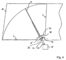
- Fig. 4
- einen Abschnitt aus einer Scheibe eines Kraftfahrzeugs mit Teilen Scheibenwischvorrichtung nach einer zweiten bevorzugten Ausführungsform der Erfindung.
- Fig. 1
- a portion of a disc of a motor vehicle with parts of a windshield wiper device according to a first preferred embodiment of the invention,
- Fig. 2
- 1 is a sectional view along the line AA in FIG. 1 when the wiper blade moves from a first end position to the second end position, FIG.
- Fig. 3
- the same view as in Fig. 2, but upon movement of the wiper blade from the second end position to the first end position, and
- Fig. 4
- a portion of a disc of a motor vehicle with parts of a windshield wiper device according to a second preferred embodiment of the invention.
In Fig. 1 ist teilweise eine Scheibe 10 eines Kraftfahrzeugs und ein Scheibenwischvorrichtung zum Wischen der Scheibe 10 nach einer ersten bevorzugten Ausführungsform der Erfindung gezeigt.In Fig. 1, a
Die Scheibenwischvorrichtung umfasst zwei gleich ausgebildete, synchron bewegte Wischerarme mit daran gehaltenen Wischblättern, von denen in Fig. 1 nur der Wischerarm 12 mit einem daran gehaltenen Wischerblatt 14 gezeigt ist, und einen in Fig. 1 nur sehr schematisch gezeigten Antrieb 15, mittels dessen die Wischarme zwischen jeweiligen Wischarmendlagen und dementsprechend die Wischblätter zwischen entsprechenden Endlagen hin- und herschwenkbar sind. In Fig. 1 sind nur die erste Endlage B und die zweite Endlage C des Wischblatts 14 gezeigt. Die Scheibenwischvorrichtung umfasst weiterhin eine Führung 16 für einen an dem Wischerarm 12 gehaltenen Läufer 18.The windshield wiper device comprises two identically formed, synchronously moved wiper arms with wiper blades held thereon, of which only the
Der Antrieb 15 treibt die Wischerarme über Antriebswellen an, von denen in Fig. 1 nur die Antriebswelle 20 gezeigt ist.The
Die Wischerarme sind in an sich bekannter Weise an den Antriebswellen in einer entsprechenden Ebene durch die jeweilige Längsachse der Antriebswelle 16 schwenkbar gelagert und werden durch in Fig. 1 nicht gezeigte elastische Elemente in Richtung der Scheibe 10 gedrückt.The wiper arms are pivotally mounted in a conventional manner to the drive shafts in a corresponding plane through the respective longitudinal axis of the
Die Wischblätter sind in an sich bekannter Weise an den Wischerarmen schwenkbar gehalten, wobei der Schwenkbereich jedoch so eingeschränkt ist, dass sie bei Abheben der Wischerarme während des Wischens nicht mit ihren Enden auf die Scheibe kippen können.The wiper blades are pivotally supported on the wiper arms in a manner known per se, but the pivoting range is limited such that they can not tip their ends onto the disk when the wiper arms are lifted off during wiping.
Während die Wischblätter konventionell aufgebaut sind und jeweils eine Wischlippe, in Fig. 2 und 3 die Wischlippe 22, aufweist, sind die Wischerarme gegenüber konventionellen Wischerarmen in zweifacher Hinsicht geändert. Da die Wischerarme gleich aufgebaut sind, genügt es, die Unterschiede nur am Beispiel des Wischerarms 12 zu erläutern.While the wiper blades are constructed conventionally and each having a wiper lip, in Figs. 2 and 3, the
Zum einen ist an dem Wischerarm 12 der Läufer 18 gehalten, der um eine parallel zu einer Längsachse des Wischerarms 12 und damit des Wischblatts 14 verlaufende Achse schwenkbar ist.On the one hand, the
Der Läufer besitzt einen an dem Wischerarm 12 schwenkbar gehaltenen, U-förmigen Halter 24, zwischen dessen freien Enden ein Läuferrad 26 drehbar gelagert ist. Das Läuferrad 26 bewegt sich in der nutenartigen Führung 16.The rotor has a pivotally held on the
Zum anderen weist der Wischerarm 12 im Bereich des Läufers 18 ein asymmetrisches U-förmiges Profil 27 auf, das Schwenkbewegungen des Läufers 18 mit den jeweils freien Schenkeln zwischen zwei Läuferendlagen begrenzt. Durch die asymmetrische Ausbildung wird erreicht, dass der Läufer 18 bei Schwenkung in den beiden möglichen Schwenkrichtungen unterschiedlich große maximale Schwenkwinkel gegenüber einer Normalen auf die Scheibe 10 erreichen kann. Beispielsweise ist in den Fig. 2 und 3 der Läufer 18 nach links mit einem größeren Winkel zur Seite schwenkbar als nach rechts, da er jeweils an den freien Enden des asymmetrischen U-förmigen Profils 27 anschlägt.On the other hand, the
Die Führung 16 ist als kreissegmentförmige Nut ausgebildet, die im Längsschnitt genauer in den Fig. 2 und 3 gezeigt ist. Jeweils an den Enden der Führung 16 sind Vertiefungen 28, 28' vorgesehen, in die das Läuferrad 26 kurzzeitig einrastet, wenn der Wischerarm 12 die entsprechenden Wischerarmendlagen bzw. das Wischblatt 14 die entsprechenden Endlagen B bzw. C erreicht hat.The
Das asymmetrische, U-förmige Profil 27 des Wischerarms 12 im Bereich des Läufers 18, die Länge der freien Schenkel des U-förmigen Halters 24, der Durchmesser des Läuferrades 16 und der Abstand des Wischerarms 12 von der Führung 16 sind so gewählt, dass bei einer Bewegung des Wischblatts 14 von der Endlage B in die Endlage C bzw. einer entsprechenden Bewegung des Wischerarms 14 das Läuferrad 26 nur von dem Eigengewicht des Läufers 18 auf die Führung 16 gedrückt wird, so dass das Wischblatt 14 mit dem normalen Anpressdruck mit seiner Wischlippe 22 auf der Scheibe 10 aufliegt. Bei Erreichen der Endlage C bleibt das Läuferrad 26 in der rechten Vertiefung 28' der Führung 16 hängen, so dass es nach Bewegung des Wischblatts 14 aus der zweiten Endlage C in Richtung der ersten Endlage B umschlägt, dabei an den entsprechenden Abschnitt des U-förmigen Profils 27 des Wischerarms 12 anschlägt, die zweite Läuferendlage einnimmt und so den Wischerarm 12 mit dem Wischblatt 14 soweit anhebt, dass die Wischlippe 22 des Wischblatts 14 dabei von der Scheibe 10 abgehoben wird (vgl. Fig. 3).The asymmetrical,
Das asymmetrische U-förmige Profil 27, der Läufer 18 und die Führung 16 bilden daher eine Wischblattstelleinrichtung im Sinne der vorliegenden Erfindung.The asymmetrical
Durch die Wahl der ersten und der zweiten Endlage für das Wischblatt 14 weist bei einer Vorwärtsfahrt des Kraftfahrzeugs die Bewegung der auf der Scheibe 10 aufliegenden Wischlippe 22 über die gesamte Bewegungsbahn eine in Richtung des Fahrtwindes verlaufende Komponente auf.By the choice of the first and the second end position for the
Bei einer Bewegung des Wischblatts 14 von der Endlage B in die Endlage C liegt also die Wischlippe 22 auf der Scheibe 10 auf, bei der Bewegung in der umgekehrten Richtung jedoch nicht, der der Wischerarm 12 angehoben und damit das Wischblatt 14 mit der Wischlippe 22 von der Scheibe 10 abgehoben wird.During a movement of the
Bei einer in Fig. 4 veranschaulichten, zweiten bevorzugten Ausführungsform der Erfindung wird das Wischblatt gedreht, um die Wischlippe von der Scheibe abzuheben. Da die Scheibenwischvorrichtung sich von der Scheibenwischvorrichtung des ersten Ausführungsbeispiels nur in der Ausbildung des Wischarms unterscheidet, werden für die anderen Teile die gleichen Bezugszeichen verwendet und es gelten die gleichen Erläuterungen.In a second preferred embodiment of the invention illustrated in FIG. 4, the wiper blade is rotated to lift the wiper lip from the disk. Since the windshield wiper device differs from the windshield wiper device of the first embodiment only in the configuration of the wiper arm, the same reference numerals are used for the other parts and the same explanations apply.
Der Wischerarm 12' weist im Unterschied zu dem vorstehend beschriebenen Wischerarm 12 in dem Abschnitt zwischen der Antriebswelle 14 und dem Läufer 18 ein Drehgelenk 30 auf, mittels dessen ein freies Ende 32 des Wischerarms 12' gegenüber dem mit der Antriebswelle 20 verbundenen Abschnitt 34 drehbar ist.The wiper arm 12 ', in contrast to the
Bei einer Bewegung des Wischblatts 14 von der ersten Endlage B in die zweite Endlage C nimmt der Läufer 18 die in Fig. 2 gezeigte Läuferendlage ein, in der die Wischlippe 22 auf der Scheibe 10 aufliegt.When the
Bei Erreichen der zweiten Endlage C und Umkehr der Bewegung in Richtung der ersten Endlage B wird der Läufer 18 in die in Fig. 3 gezeigte Läuferendlage geklappt, wobei nun das freie Ende 32 des Wischarms 12' und damit das Wischblatt 14 in Fig. 3 gegen den Uhrzeigersinn gedreht bzw. geschwenkt wird, so dass die Wischlippe 22, nicht aber der Wischarm 12' von der Scheibe abgehoben wird.Upon reaching the second end position C and reversing the movement in the direction of the first end position B of the
Bei diesem Ausführungsbeispiel bilden also das Drehgelenk 30, der Läufer 18 und die Führung 16 die Wischblattstelleinrichtung, wobei der Läufer 18 und die Führung 16 eine Dreh- bzw. Schwenkeinrichtung bilden.In this embodiment, therefore, form the swivel joint 30, the
- 1010
- Scheibedisc
- 12, 12'12, 12 '
- Wischerarmwiper
- 1414
- Wischblattwiper blade
- 1515
- Antriebdrive
- 1616
- Führungguide
- 1818
- Läuferrunner
- 2020
- Antriebswelledrive shaft
- 2222
- Wischlippewiper lip
- 2424
- Halterholder
- 2626
- Läuferradimpeller
- 28, 28'28, 28 '
- Vertiefungenwells
- 3030
- Drehgelenkswivel
- 3232
- freies Endefree end
- 3434
- Abschnittsection
Claims (12)
- A method of wiping a windshield or other glass (10) of a motor vehicle, wherein at least one wiper blade (14) is moved to and fro between a first end position and a second end position, wherein a wiping lip (22) of the wiper blade (14) lies continuously on the windshield or other glass (10) during the movement from the first end position into the second position, but not during the total movement in the opposite direction,
characterized in that
that the speed of the motor vehicle is detected; and
in that the wiping lip (22) is only removed from the windshield or other glass (10) during wiping, when the speed lies in a pre-determined interval - A method in accordance with claim 1, characterized in that the first end position and the second end position are selected such that, when the motor vehicle travels forward, the movement of the wiping lip (22) lying on the windshield or other glass (10) has a component extending in the direction of the headwind on at least half of the movement track of the wiper blade (14).
- A method in accordance with claim 1 or claim 2, characterized in that the wiper blade (14) is rotated or pivoted about an axis aligned substantially parallel to a longitudinal axis of the wiper blade (14) in order to bring the wiping lip (22) into contact with the windshield or other glass (10) or to move it away from the windshield or other glass (10).
- A method in accordance with any one of the preceding claims, characterized in that the wiper blade (14) is lowered or raised relative to the surface of the windshield or other glass (10) in order to bring the wiping lip (22) into contact with the windshield or other glass (10) or to lift it from the windshield or other glass (10).
- A method in accordance with any one of the preceding claims, characterized in that the wiper blade (14) is pivoted to and fro between the end positions.
- An apparatus for wiping a windshield or other glass for wiping a windshield or other glass (10) of a motor vehicle comprising
at least one wiper arm (12; 12') for the holding of a wiper blade (14) and movable to and fro by a drive (20) between a first wiper arm end position and a second wiper arm end position; and
a wiper blade setting device (16, 18, 27; 16, 18, 27, 30) by means of which the wiper arm (12; 12') and/or the wiper blade (14) is movable to and fro between two positions such that the wiping lip (22) of the wiper blade (14) lies on the windshield or other glass (10) in a first position during a movement from the first wiper arm end position into the second wiper arm end position, but not in the second position during the total movement in the opposite direction and such that it comprises a control device for the control of the wiper blade setting device to which a signal reflecting the speed of the motor vehicle can be supplied and by means of which the wiper blade setting device can be controlled such that a removal of the wiping lip from the windshield or other glass during wiping only takes place when the speed lies in a pre-determined interval. - An apparatus for wiping a windshield or other glass in accordance with claim 6, characterized in that the first wiper arm end position and the second wiper arm end position are selected such that, when the vehicle travels forward, the movement of the wiping lip (22) lying on the windshield or other glass (10) has a component extending in the direction of the headwind on at least half of the movement track of the wiper blade (14)
- An apparatus for wiping a windshield or other glass in accordance with claim 6 or claim 7, characterized in that the wiper blade setting device (16, 18, 30) includes a rotary or pivot device (16, 18) by means of which the wiper arm (12; 12') and/ or the wiper blade (14) can be rotated or pivoted about an axis aligned substantially parallel to a longitudinal axis of the wiper blade (14) to bring the wiping lip (22) into contact with the windshield or other glass (10) or to move it away from the windshield or other glass (10).
- An apparatus for wiping a windshield or other glass in accordance with any one of claims 6 to 8, characterized in that the wiper blade setting device (16, 18, 27) is made such that the wiper arm (12, 12') can be lowered or raised relative to the surface of the windshield or other glass (10) to bring the wiping lip (22) into contact with the windshield or other glass (10) or to lift it from the windshield or other glass (10).
- An apparatus for wiping a windshield or other glass in accordance with any one of the claims 6 to 9, characterized
in that the wiper blade setting device (16, 18, 27) includes a runner (18) pivotably held between two runner end positions at the wiper arm (12; 12') parallel to the direction of movement of the wiper blade (14) and running on the windshield or other glass (10) or on a guide; and
in that the wiper arm (12; 12') and/or the runner (18) are made such that the wiping lip (22) lies on the windshield or other glass (10) when the runner adopts the one runner end position, and does not contact the windshield or other glass (10) when the runner adopts the other runner end position. - An apparatus for wiping a windshield or other glass in accordance with any one of the claims 6 to 10, characterized in that the wiper arm can be raised or lowered by means of a coupling transmission connected to a drive of the apparatus for wiping a windshield or other glass and to the wiper arm.
- An apparatus for wiping a windshield or other glass in accordance with any one of the claims 6 to 11, characterized in that the wiper arm (12; 12') is pivotable to and fro between its wiper arm end positions.
Priority Applications (3)
| Application Number | Priority Date | Filing Date | Title |
|---|---|---|---|
| AT04008014T ATE315505T1 (en) | 2004-04-01 | 2004-04-01 | METHOD FOR WIPERING A WINDOW OF A MOTOR VEHICLE AND WINDSHIELD WIPER DEVICE |
| DE502004000238T DE502004000238D1 (en) | 2004-04-01 | 2004-04-01 | Method for wiping a window of a motor vehicle and windshield wiper device |
| EP04008014A EP1582425B1 (en) | 2004-04-01 | 2004-04-01 | Method of wiping a windshield of a vehicle and windshield wiping device |
Applications Claiming Priority (1)
| Application Number | Priority Date | Filing Date | Title |
|---|---|---|---|
| EP04008014A EP1582425B1 (en) | 2004-04-01 | 2004-04-01 | Method of wiping a windshield of a vehicle and windshield wiping device |
Publications (2)
| Publication Number | Publication Date |
|---|---|
| EP1582425A1 EP1582425A1 (en) | 2005-10-05 |
| EP1582425B1 true EP1582425B1 (en) | 2006-01-11 |
Family
ID=34878242
Family Applications (1)
| Application Number | Title | Priority Date | Filing Date |
|---|---|---|---|
| EP04008014A Expired - Lifetime EP1582425B1 (en) | 2004-04-01 | 2004-04-01 | Method of wiping a windshield of a vehicle and windshield wiping device |
Country Status (3)
| Country | Link |
|---|---|
| EP (1) | EP1582425B1 (en) |
| AT (1) | ATE315505T1 (en) |
| DE (1) | DE502004000238D1 (en) |
Family Cites Families (2)
| Publication number | Priority date | Publication date | Assignee | Title |
|---|---|---|---|---|
| DE1246442B (en) * | 1963-02-19 | 1967-08-03 | Marian Trzebinski | Lifting device for a motor vehicle wiper |
| DE1480726A1 (en) * | 1965-09-15 | 1970-04-23 | Zuse Dipl Ing Dr Konrad | Method and device for automatic windshield wiping, in particular on motor vehicles |
-
2004
- 2004-04-01 DE DE502004000238T patent/DE502004000238D1/en not_active Expired - Lifetime
- 2004-04-01 EP EP04008014A patent/EP1582425B1/en not_active Expired - Lifetime
- 2004-04-01 AT AT04008014T patent/ATE315505T1/en not_active IP Right Cessation
Also Published As
| Publication number | Publication date |
|---|---|
| DE502004000238D1 (en) | 2006-04-06 |
| ATE315505T1 (en) | 2006-02-15 |
| EP1582425A1 (en) | 2005-10-05 |
Similar Documents
| Publication | Publication Date | Title |
|---|---|---|
| DE3525215C2 (en) | ||
| DE4028494C2 (en) | Windshield wipers for motor vehicles | |
| DE10159052A1 (en) | Windscreen wiper device, in particular for a motor vehicle | |
| DE1906440A1 (en) | Drive device for vehicle wipers | |
| DE2203269C3 (en) | Windshield washer for trapezoidal windows | |
| EP1582425B1 (en) | Method of wiping a windshield of a vehicle and windshield wiping device | |
| DE3903681A1 (en) | DRIVE DEVICE FOR A WINDOW WIPER, IN PARTICULAR OF MOTOR VEHICLES | |
| DE3707837C2 (en) | ||
| DE202017106396U1 (en) | Extendable windscreen wiper system | |
| DE4104632C2 (en) | ||
| DE2116864A1 (en) | Windshield washer systems for vehicles, in particular motor vehicles | |
| DE19949446C2 (en) | Windshield wiper assembly for a windshield | |
| DE2413290A1 (en) | WIPER DEVICE FOR HEADLIGHTS OF MOTOR VEHICLES | |
| DE102010008211A1 (en) | Drive device for wiping device of motor vehicle, has eccentric cam controlled by steering wheel, where supporting axle of steering wheel is spaced from drive axle and supported at stationary counter bearing over connecting part | |
| DE102004029080B4 (en) | Windscreen wiper device for a rear window of a vehicle | |
| DE19501849A1 (en) | Windscreen wiper blade for vehicle | |
| DE19709654C2 (en) | Wiping device | |
| DE2420675C3 (en) | Windshield wiper devices, in particular for front glass panes of headlights for motor vehicles | |
| DE3931520C2 (en) | Insect cleaning device for vehicle windows | |
| DE2507314A1 (en) | Pivoted mounting for windscreen wiper blade - has cable drive loop through hollow wiper arm to adjust blade angle | |
| DE2547661C2 (en) | ||
| WO2005118362A1 (en) | Drive device for a wiper arm of a windscreen wiper unit | |
| DE19751461B4 (en) | Wiper device over a window of a vehicle | |
| DE102011108911A1 (en) | Windscreen wiper system for removing rainwater from e.g. front window pane of motor car, has control unit to control and/or regulate motor such that magnitude of acceleration of windscreen wiper during tilting of wiper lip is smaller | |
| DE102012206957A1 (en) | Wiper arm device has spring unit that is coupled with wiper arm against spring force movable with wiper arm fixing element, and whose spring force is changed by adjusting unit |
Legal Events
| Date | Code | Title | Description |
|---|---|---|---|
| GRAP | Despatch of communication of intention to grant a patent |
Free format text: ORIGINAL CODE: EPIDOSNIGR1 |
|
| GRAS | Grant fee paid |
Free format text: ORIGINAL CODE: EPIDOSNIGR3 |
|
| PUAI | Public reference made under article 153(3) epc to a published international application that has entered the european phase |
Free format text: ORIGINAL CODE: 0009012 |
|
| 17P | Request for examination filed |
Effective date: 20041208 |
|
| AK | Designated contracting states |
Kind code of ref document: A1 Designated state(s): AT BE BG CH CY CZ DE DK EE ES FI FR GB GR HU IE IT LI LU MC NL PL PT RO SE SI SK TR |
|
| AX | Request for extension of the european patent |
Extension state: AL HR LT LV MK |
|
| GRAA | (expected) grant |
Free format text: ORIGINAL CODE: 0009210 |
|
| AK | Designated contracting states |
Kind code of ref document: B1 Designated state(s): AT BE BG CH CY CZ DE DK EE ES FI FR GB GR HU IE IT LI LU MC NL PL PT RO SE SI SK TR |
|
| PG25 | Lapsed in a contracting state [announced via postgrant information from national office to epo] |
Ref country code: RO Free format text: LAPSE BECAUSE OF FAILURE TO SUBMIT A TRANSLATION OF THE DESCRIPTION OR TO PAY THE FEE WITHIN THE PRESCRIBED TIME-LIMIT Effective date: 20060111 Ref country code: SI Free format text: LAPSE BECAUSE OF FAILURE TO SUBMIT A TRANSLATION OF THE DESCRIPTION OR TO PAY THE FEE WITHIN THE PRESCRIBED TIME-LIMIT Effective date: 20060111 Ref country code: FI Free format text: LAPSE BECAUSE OF FAILURE TO SUBMIT A TRANSLATION OF THE DESCRIPTION OR TO PAY THE FEE WITHIN THE PRESCRIBED TIME-LIMIT Effective date: 20060111 Ref country code: GB Free format text: LAPSE BECAUSE OF FAILURE TO SUBMIT A TRANSLATION OF THE DESCRIPTION OR TO PAY THE FEE WITHIN THE PRESCRIBED TIME-LIMIT Effective date: 20060111 Ref country code: PL Free format text: LAPSE BECAUSE OF FAILURE TO SUBMIT A TRANSLATION OF THE DESCRIPTION OR TO PAY THE FEE WITHIN THE PRESCRIBED TIME-LIMIT Effective date: 20060111 Ref country code: SK Free format text: LAPSE BECAUSE OF FAILURE TO SUBMIT A TRANSLATION OF THE DESCRIPTION OR TO PAY THE FEE WITHIN THE PRESCRIBED TIME-LIMIT Effective date: 20060111 Ref country code: IE Free format text: LAPSE BECAUSE OF FAILURE TO SUBMIT A TRANSLATION OF THE DESCRIPTION OR TO PAY THE FEE WITHIN THE PRESCRIBED TIME-LIMIT Effective date: 20060111 Ref country code: NL Free format text: LAPSE BECAUSE OF FAILURE TO SUBMIT A TRANSLATION OF THE DESCRIPTION OR TO PAY THE FEE WITHIN THE PRESCRIBED TIME-LIMIT Effective date: 20060111 |
|
| REG | Reference to a national code |
Ref country code: CH Ref legal event code: EP |
|
| REG | Reference to a national code |
Ref country code: IE Ref legal event code: FG4D Free format text: LANGUAGE OF EP DOCUMENT: GERMAN |
|
| PG25 | Lapsed in a contracting state [announced via postgrant information from national office to epo] |
Ref country code: AT Free format text: LAPSE BECAUSE OF NON-PAYMENT OF DUE FEES Effective date: 20060401 |
|
| REF | Corresponds to: |
Ref document number: 502004000238 Country of ref document: DE Date of ref document: 20060406 Kind code of ref document: P |
|
| PG25 | Lapsed in a contracting state [announced via postgrant information from national office to epo] |
Ref country code: SE Free format text: LAPSE BECAUSE OF FAILURE TO SUBMIT A TRANSLATION OF THE DESCRIPTION OR TO PAY THE FEE WITHIN THE PRESCRIBED TIME-LIMIT Effective date: 20060411 Ref country code: BG Free format text: LAPSE BECAUSE OF FAILURE TO SUBMIT A TRANSLATION OF THE DESCRIPTION OR TO PAY THE FEE WITHIN THE PRESCRIBED TIME-LIMIT Effective date: 20060411 Ref country code: DK Free format text: LAPSE BECAUSE OF FAILURE TO SUBMIT A TRANSLATION OF THE DESCRIPTION OR TO PAY THE FEE WITHIN THE PRESCRIBED TIME-LIMIT Effective date: 20060411 |
|
| PG25 | Lapsed in a contracting state [announced via postgrant information from national office to epo] |
Ref country code: ES Free format text: LAPSE BECAUSE OF FAILURE TO SUBMIT A TRANSLATION OF THE DESCRIPTION OR TO PAY THE FEE WITHIN THE PRESCRIBED TIME-LIMIT Effective date: 20060422 |
|
| PG25 | Lapsed in a contracting state [announced via postgrant information from national office to epo] |
Ref country code: MC Free format text: LAPSE BECAUSE OF NON-PAYMENT OF DUE FEES Effective date: 20060430 Ref country code: BE Free format text: LAPSE BECAUSE OF NON-PAYMENT OF DUE FEES Effective date: 20060430 |
|
| PG25 | Lapsed in a contracting state [announced via postgrant information from national office to epo] |
Ref country code: PT Free format text: LAPSE BECAUSE OF FAILURE TO SUBMIT A TRANSLATION OF THE DESCRIPTION OR TO PAY THE FEE WITHIN THE PRESCRIBED TIME-LIMIT Effective date: 20060612 |
|
| AKX | Designation fees paid |
Designated state(s): AT BE BG CH CY CZ DE DK EE ES FI FR GB GR HU IE IT LI LU MC NL PL PT RO SE SI SK TR |
|
| NLV1 | Nl: lapsed or annulled due to failure to fulfill the requirements of art. 29p and 29m of the patents act | ||
| GBV | Gb: ep patent (uk) treated as always having been void in accordance with gb section 77(7)/1977 [no translation filed] |
Effective date: 20060111 |
|
| ET | Fr: translation filed | ||
| REG | Reference to a national code |
Ref country code: IE Ref legal event code: FD4D |
|
| PLBE | No opposition filed within time limit |
Free format text: ORIGINAL CODE: 0009261 |
|
| STAA | Information on the status of an ep patent application or granted ep patent |
Free format text: STATUS: NO OPPOSITION FILED WITHIN TIME LIMIT |
|
| 26N | No opposition filed |
Effective date: 20061012 |
|
| BERE | Be: lapsed |
Owner name: DELPHI TECHNOLOGIES, INC. Effective date: 20060430 |
|
| PG25 | Lapsed in a contracting state [announced via postgrant information from national office to epo] |
Ref country code: CZ Free format text: LAPSE BECAUSE OF FAILURE TO SUBMIT A TRANSLATION OF THE DESCRIPTION OR TO PAY THE FEE WITHIN THE PRESCRIBED TIME-LIMIT Effective date: 20060111 Ref country code: GR Free format text: LAPSE BECAUSE OF FAILURE TO SUBMIT A TRANSLATION OF THE DESCRIPTION OR TO PAY THE FEE WITHIN THE PRESCRIBED TIME-LIMIT Effective date: 20060412 |
|
| PG25 | Lapsed in a contracting state [announced via postgrant information from national office to epo] |
Ref country code: EE Free format text: LAPSE BECAUSE OF FAILURE TO SUBMIT A TRANSLATION OF THE DESCRIPTION OR TO PAY THE FEE WITHIN THE PRESCRIBED TIME-LIMIT Effective date: 20060111 |
|
| PG25 | Lapsed in a contracting state [announced via postgrant information from national office to epo] |
Ref country code: TR Free format text: LAPSE BECAUSE OF FAILURE TO SUBMIT A TRANSLATION OF THE DESCRIPTION OR TO PAY THE FEE WITHIN THE PRESCRIBED TIME-LIMIT Effective date: 20060111 Ref country code: LU Free format text: LAPSE BECAUSE OF NON-PAYMENT OF DUE FEES Effective date: 20060401 Ref country code: HU Free format text: LAPSE BECAUSE OF FAILURE TO SUBMIT A TRANSLATION OF THE DESCRIPTION OR TO PAY THE FEE WITHIN THE PRESCRIBED TIME-LIMIT Effective date: 20060712 |
|
| PG25 | Lapsed in a contracting state [announced via postgrant information from national office to epo] |
Ref country code: CY Free format text: LAPSE BECAUSE OF FAILURE TO SUBMIT A TRANSLATION OF THE DESCRIPTION OR TO PAY THE FEE WITHIN THE PRESCRIBED TIME-LIMIT Effective date: 20060111 |
|
| REG | Reference to a national code |
Ref country code: CH Ref legal event code: PL |
|
| PG25 | Lapsed in a contracting state [announced via postgrant information from national office to epo] |
Ref country code: LI Free format text: LAPSE BECAUSE OF NON-PAYMENT OF DUE FEES Effective date: 20080430 Ref country code: CH Free format text: LAPSE BECAUSE OF NON-PAYMENT OF DUE FEES Effective date: 20080430 |
|
| REG | Reference to a national code |
Ref country code: FR Ref legal event code: PLFP Year of fee payment: 13 |
|
| REG | Reference to a national code |
Ref country code: FR Ref legal event code: PLFP Year of fee payment: 14 |
|
| REG | Reference to a national code |
Ref country code: FR Ref legal event code: PLFP Year of fee payment: 15 |
|
| REG | Reference to a national code |
Ref country code: DE Ref legal event code: R082 Ref document number: 502004000238 Country of ref document: DE Representative=s name: MANITZ FINSTERWALD PATENT- UND RECHTSANWALTSPA, DE Ref country code: DE Ref legal event code: R082 Ref document number: 502004000238 Country of ref document: DE Representative=s name: MANITZ FINSTERWALD PATENTANWAELTE PARTMBB, DE Ref country code: DE Ref legal event code: R081 Ref document number: 502004000238 Country of ref document: DE Owner name: APTIV TECHNOLOGIES LIMITED, BB Free format text: FORMER OWNER: DELPHI TECHNOLOGIES, INC., TROY, MICH., US |
|
| PGFP | Annual fee paid to national office [announced via postgrant information from national office to epo] |
Ref country code: IT Payment date: 20190423 Year of fee payment: 16 |
|
| PGFP | Annual fee paid to national office [announced via postgrant information from national office to epo] |
Ref country code: FR Payment date: 20190425 Year of fee payment: 16 |
|
| PG25 | Lapsed in a contracting state [announced via postgrant information from national office to epo] |
Ref country code: FR Free format text: LAPSE BECAUSE OF NON-PAYMENT OF DUE FEES Effective date: 20200430 |
|
| PG25 | Lapsed in a contracting state [announced via postgrant information from national office to epo] |
Ref country code: IT Free format text: LAPSE BECAUSE OF NON-PAYMENT OF DUE FEES Effective date: 20200401 |
|
| P01 | Opt-out of the competence of the unified patent court (upc) registered |
Effective date: 20230425 |
|
| PGFP | Annual fee paid to national office [announced via postgrant information from national office to epo] |
Ref country code: DE Payment date: 20230426 Year of fee payment: 20 |
|
| REG | Reference to a national code |
Ref country code: DE Ref legal event code: R071 Ref document number: 502004000238 Country of ref document: DE |