EP1582424A2 - Vorrichtung zum Aufstellen der Fronthaube eines Kraftfahrzeuges zumindest im frontseitigen Haubenschlossbereich - Google Patents
Vorrichtung zum Aufstellen der Fronthaube eines Kraftfahrzeuges zumindest im frontseitigen Haubenschlossbereich Download PDFInfo
- Publication number
- EP1582424A2 EP1582424A2 EP05004608A EP05004608A EP1582424A2 EP 1582424 A2 EP1582424 A2 EP 1582424A2 EP 05004608 A EP05004608 A EP 05004608A EP 05004608 A EP05004608 A EP 05004608A EP 1582424 A2 EP1582424 A2 EP 1582424A2
- Authority
- EP
- European Patent Office
- Prior art keywords
- reversing
- piston
- pawl
- lifting element
- front hood
- Prior art date
- Legal status (The legal status is an assumption and is not a legal conclusion. Google has not performed a legal analysis and makes no representation as to the accuracy of the status listed.)
- Granted
Links
Images




Classifications
-
- B—PERFORMING OPERATIONS; TRANSPORTING
- B60—VEHICLES IN GENERAL
- B60R—VEHICLES, VEHICLE FITTINGS, OR VEHICLE PARTS, NOT OTHERWISE PROVIDED FOR
- B60R21/00—Arrangements or fittings on vehicles for protecting or preventing injuries to occupants or pedestrians in case of accidents or other traffic risks
- B60R21/34—Protecting non-occupants of a vehicle, e.g. pedestrians
- B60R21/38—Protecting non-occupants of a vehicle, e.g. pedestrians using means for lifting bonnets
-
- E—FIXED CONSTRUCTIONS
- E05—LOCKS; KEYS; WINDOW OR DOOR FITTINGS; SAFES
- E05B—LOCKS; ACCESSORIES THEREFOR; HANDCUFFS
- E05B77/00—Vehicle locks characterised by special functions or purposes
- E05B77/02—Vehicle locks characterised by special functions or purposes for accident situations
- E05B77/08—Arrangements for protection of pedestrians
Definitions
- the invention relates to a device for the protection of Persons in a frontal impact on a motor vehicle by active Setting up the front hood at least in the front Hood lock area, consisting of a positioning element with a body-mounted housing and a linear guided, with the hood lock connected lifting element, the sensor-controlled by means of a spring store by a predetermined stroke below Installation of the front hood is extendable, and that one device has to reversing the established lifting element.
- a solution principle is the aforementioned to defuse hard transitional area to the windshield, d. H. more compliant, e.g. through a sensor-controlled inflatable airbag or according to DE 28 14 107 A in conjunction with DE 28 41 315 actuated by a means of an impact sensor Device for adjusting the front hood from a rest position in a contrast raised, resilient impact position, d. H. a so-called "active front hood". Because of the front hood in the collision detected by the impact sensor with a Pedestrians in one opposite their rest - d. H. Normally, position raised impact position is displaced, will be a Breast or head impact of the pedestrian in the sense of a cheaper Energy degradation to the effect of coming deformation of the Vehicle body created for reduced head and Breast delays and thus ensures lower injury risks.
- the front hood For active setting up the front hood serve set-up, which have a body-mounted lower part and an erectable guided lifting element in conjunction with an energy storage, which is triggered by a sensor-controlled actuator in the event of an impending accident, while the lifting element with the front cover to a predetermined stroke sets up.
- the prior art and articles of numerous, not yet published earlier applications of the patent applicant show a number of constructions for these installation elements, which typically have a spring storage in the form of a prestressable helical spring arrangement as an energy store.
- the invention is based on the object, the initially designated Form device so that by simple means without separate on-board auxiliary tools a manual or motorized Reversing the raised lifting element of erection elements in the hood lock area is possible.
- Reversing device With the vehicle fixed in the mounting element attached Reversing device is a simple inexpensive Reversible option, be it manual or motorized without separate Auxiliary tools are given on board the vehicle. Because the Reversing device operating state dependent, in particular in Basic state, can be decoupled from the lifting element, affects the Reversing device the rapid installation of the lifting element in Hazard not.
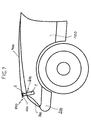
- Fig. 7 shows a schematic overview of the representation Front end of a passenger vehicle with the associated Body 100, a bumper 200 and a headlight 300.
- the front car is covered by a bonnet 400, typically the hood, the windshield side over Hinges hinged (not shown) and front over one Hood lock 500 connected to the body 100 of the front end is.
- the hood lock 500 typically consists of a body-fixed lock part 501 and one with this detachable Lockable, firmly connected to the front hood closing part (not shown).
- At the front of the front car is (at least) one Set-up element 600 for active installation of the front hood 400 in Front hood lock area in the event of a threatening frontal impact attached to a person.
- This positioning element 600 consists of a body-mounted housing 1 and a linear in it guided, connected to the lock part 501 of the hood lock Lifting element 2, the sensor controlled by means of a spring store a predetermined stroke under deployment of the front hood extendable is. This established state is shown in the overview figure.
- the yielding bonnet 400 mitigates an impact of one Person authoritative.
- hood lock stand In addition to the front hood lock stand can also Stand for the rear hinges in a conventional manner be provided.
- FIGS. 1 to 6 show embodiments of the positioning element 600 in connection with various variants of devices according to the invention for reversing the erected lifting element.
- Figures 1 - 3 show in various views a first embodiment of a reversing device for a manual hydraulically assisted reversal of the erected lifting element 2 of a raising element 600 for the hood lock.
- This positioning element 600 is suitable with its housing 1 in Way, as shown in Fig. 7, on the body 100 of the Front car attached.
- a spring accumulator in the form a coil spring 3, with its lower end on Caseback 1 a and with its upper end to a circumferential Bund 2 a of the lifting element 2 is supported, which is also used to guide the Hubides serves.
- the Coil spring 3 biased, wherein a releasable holding device the lifting element 2 against the biasing force of the coil spring. 3 holds down.
- the releasable holding device has at least two opposite, hinged in recesses of the lifting element 2 Latches 4 on. They each have a shoulder 4 a, with which they be supported on a housing-fixed stop 1 b. Through this Verklinkung the lifting element 2 is prevented due to the Pretension force of the coil spring 3 extend.
- the latches 4 are each under the biasing force of a Leg spring 5 which tries to release the respective latch under suspension the latching to the center of the hollow cylindrical lifting element out to pivot.
- This pivoting is shown in the Basic state prevented by a locking member 6, with a trigger pin 7 a of a sensor-controlled actuator 7 is connected is. If the actuator, e.g. formed by a trigger magnet is activated in the event of an imminent accident, the Trigger pin 7 a with the locking member 6 against the force of a Return spring 8 retracted.
- the set-up element shown is only as appropriate Embodiment to understand. It can be another Construction, including the design of the releasable holding device. Such Aufstellelemente be, for example, in described earlier German patent applications of the applicant.
- This hydraulic system is in a second chamber of the housing 1 next to the releasable holding device and the reciprocating piston housed and is about a Reversierklinke 9 with control contours in controlled operative connection with the reciprocating piston.
- the hydraulic system consists of a working piston 11, the is preferably designed as a telescopic piston, and the sealing in a housing socket 1 c is linearly guided and an actuating head part 11 a in the form of a rubber buffer, and one in the associated housing chamber guided Reversierkolben 12, the one central bore 12 a for receiving the lower end of Working piston 11 having a predetermined annular gap 12 b.
- the reversing piston 12 is by means of a circumferential seal 13th sealed against the upper chamber wall. He also owns a bore 12 c, accommodated in the piston Aufstellfeder 14 is, which is supported with its lower end on the housing bottom 1 a.
- Reversierkolben 12 On Reversierkolben 12 is also the Reversierklinke 9 via a Bolt 9 b, biased by a leg spring 9 c, rotatable hinged. On this Reversierklinke 9 is a Abstweilklinke 15, biased by another leg spring 15 a, rotatably articulated.
- the hydraulic system works as follows:
- the head part 11 a is in the basic position at the bottom of Front hood on. If after a successful installation of the Hubiatas 2, the front cover is opened, the Piston lift spring 14 push the reversing piston 12 upwards. In this case, the hydraulic oil 16 is displaced, via the annular gap 12 b in the central bore 12 a flows under the working piston 11 and put this up. To reverse the lifting element of the Working piston 11 directly by hand or indirectly via the closing Front hood pressed in. This case over the annular gap 12 b back displaced hydraulic oil acts on the top of the Reversierkolbens 12 and pushes it down.
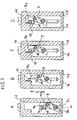
- the pawl nose 9a of the Reversierklinke 9 is latched to the draw hook 10, thereby takes on the Reversierkolben 12 hinged Reversierklinke 9 the lifting element 2 with down to the ground state. Due to the different sizes Areas of the working piston 11 and the reversing piston 12, can the manually applied pressure in the hydraulic system easily tension the raising spring 3 of the positioning element.
- the reversing pawl is within a section of an inner housing wall 1 d arranged and has control contours, with the Housing wall depending on the position of the lifting element, i.e. the remindyakhakens 10 and the Reversierkolben 12, on which the Reversing pawl 9 is hinged on the bolt 9 b, in occur controlling active compound.
- the leg spring 9 c spans it the reversing pawl 9 counterclockwise, i. in the latching against, whereas the leg spring 15 a, the Abstützklinke 15 in Clockwise biased.
- the Abstützklinke 15 is supported at one corner of the housing 1 d and twisted against the bias of the Leg spring 15 a, whereby the Reversierklinke 9 continue can.
- the Abstützklinke could also on the Support the draw hooks 10 and turn them (figure C).
- the figures 4 and 5 a reversing system with a Bowden cable 17.
- the traction cable 17 a This Bowden cable is with one end by means of a conventional nipple or the like mounted in a slider 18, which in a Recess 1 e of the housing 1 is recorded linearly.
- this slider 18 is the Reversierklinke 9 by means of the bolt. 9 rotatably mounted, analogous to the pin bearing in Reversierkolben in first embodiment.
- the other end of the pull rope is, for example, with the Front hood or the door of the car in operative connection, that this Vehicle parts can be used as a lever for manual reversing can.
- This is when opening the front hood or the door at a established lifting element the pull cable 17 a of the Bowden cable with the Slider 18 and the Reversierklinke 9 analogous to the figure parts of Fig. 3 pushed upward until the latch nose 9 a on Retracting hook 10 hooks.
- the Reversierklinke 9 again automatically from Retracting hook 10 unlocks.
- the traction cable 17 a can directly at a suitable location of the Front hood attached. But it can also be with an im Front end articulated, biased in the upright sense Reversing lever be connected to the closed front hood of this is depressed and when opening the front hood itself automatically sets up and the reversing pawl via the pull rope raises if the lifting element is set up.
- FIG 6 is a third embodiment of Reversing device according to the invention with a self-acting controlled Reversierklinke shown.
- the associated Set-up element the so-called actuator
- the associated Set-up element is also identical to the one according to the first embodiment, so that the for better clarity also only a few essentials Components of the actuators are provided with reference numerals.
- the actuator can also in other ways be educated.
- Essential is the linearly deployable lifting element with the attached hood lock.
- the illustrated in Fig. 6 embodiment of the reversing unit has an electric motor driven Reversierklinke 9, the over the bolt 9 b is pivoted in a reversing nut 19, on.
- the reversing nut 19 is in threaded operative connection with a vertically in the housing 1 extending, rotatably mounted Threaded spindle 20, the head side via a transmission gear 21 with a housed in the housing 1 electric motor 22 is.
- the electric motor 22 moves the reversing nut 19 with the Reversierklinke 9 upward until the latter latched to the return hook 10. After reversal of the Direction of rotation then moves the electric motor 22 with the reversing nut 19 Reversing pawl 9 down, with entrainment of the lifting element 2 to to its spans. By driving a small overstroke is then, as in the embodiments described above, the lifting element unlocked again, and is thus ready for a new lineup.
Landscapes
- Engineering & Computer Science (AREA)
- Mechanical Engineering (AREA)
- Superstructure Of Vehicle (AREA)
- Lock And Its Accessories (AREA)
- Body Structure For Vehicles (AREA)
Abstract
Description
Der Stand der Technik und Gegenstände von zahlreichen, noch nicht veröffentlichten älteren Anmeldungen der Patentanmelderin, zeigen eine Reihe von Konstruktionen für diese Aufstellelemente, die typischerweise als Energiespeicher einen Federspeicher in Form einer vorspannbaren Schraubenfeder-Anordnung besitzen.
- Fig. 1
- in einer isometrischen Darstellung mit weggebrochener Gehäuse-Frontwand ein Aufstellelement zum Aufstellen der Fronthaube eines PKW im Haubenschloßbereich im Grundzustand mit einer ersten, hydraulisch betätigbaren Ausführungsform der erfindungsgemäßen Reversiereinrichtung mittels einer gesteuerten Reversierklinke,
- Fig. 2
- einer Längsschnitt-Darstellung den inneren Aufbau des Aufstellelementes nach Fig. 1,
- Fig.3
- in sieben Figurenteilen A - G die positionsabhängig gesteuerte Wirkverbindung zwischen Reversierklinke und dem Hubelement des Aufstellelementes,
- Fig. 4
- in einer weiteren isometrischen Darstellung des Aufstellelementes nach Fig. 1 eine zweite Ausführungsform der erfindungsgemäßen Reversiereinrichtung mit einer gesteuerten Reversierklinke, die über einen Bowdenzug betätigbar ist,
- Fig. 5
- eine Längsschnitt-Darstellung des Aufstellelementes mit Reversiereinrichtung nach Fig. 4,
- Fig. 6
- in einer Längsschnitt-Darstellung ein Aufstellelement entsprechend den Figuren 1 und 4 mit einer dritten Ausführungsform der erfindungsgemäßen Reversiereinrichtung mit gesteuerter Reversierklinke, die mittels eines elektromotorisch angetriebenen Spindel-/Mutter-Antriebes linear bewegbar ist, und
- Fig. 7
- in einer Übersichts-Darstellung den Vorderwagen eines PKW mit aufgestellter Fronthaube im Haubenschlossbereich durch ein Aufstellelement.
Die Figuren 1 - 3 zeigen in verschiedenen Darstellungen eine erste Ausführungsform einer Reversiereinrichtung für eine manuelle hydraulisch unterstützte Reversierung des aufgestellten Hubelementes 2 eines Aufstellelementes 600 für das Haubenschloß.
Wird das Hubelement 2 ausgelöst, stellt es sich um den Hub "I" auf und auch der Rückzughaken 10 erreicht seine obere Position
Da gleichzeitig die Fronthaube um diesen Hub aufgestellt ist, kann sich auch der Reversierkolben 12 unter der Wirkung der Kolbenaufstellfeder14 und damit auch die Reversierklinke 9 um diesen Hub aufstellen. Die Schenkelfeder 9 c dreht dabei die Reversierklinke etwas nach innen (Figurenteil B).
- 1
- Gehäuse
- 1 a
- Gehäuseboden
- 1 b
- Anschlag
- 1 c
- Gehäusestutzen
- 1 d
- innere Gehäusewand
- 1 e
- Ausnehmung
- 2
- Hubelement
- 2 a
- umlaufender Bund
- 3
- Schraubenfeder
- 4
- Rastklinken
- 4 a
- Schulter
- 5
- Schenkelfeder
- 6
- Sperrglied
- 7
- Aktuator
- 7 a
- Auslösestift
- 8
- Rückstellfeder
- 9
- Reversierklinke
- 9 a
- Klinkennase
- 9 b
- Bolzen
- 9 c
- Schenkelfeder
- 10
- Rückzughaken
- 11
- Arbeitskolben
- 11 a
- Betätigungs-Kopfteil
- 12
- Reversierkolben
- 12 a
- Zentrische Bohrung
- 12 b
- Ringspalt
- 12 c
- Bohrung
- 13
- Dichtung
- 14
- Kolbenaufstellfeder
- 15
- Abstützklinke
- 15 a
- Schenkelfeder
- 16
- Hydrauliköl
- 17
- Bowdenzug
- 17 a
- Zugseil
- 18
- Gleitstück
- 19
- Reversiermutter
- 20
- Gewindespindel
- 21
- Übersetzungsgetriebe
- 22
- Elektromotor
- 100
- Karosse
- 200
- Stoßfänger
- 300
- Scheinwerfer
- 400
- Fronthaube
- 500
- Haubenschloß
- 501
- karosseriefestes Schließteil
- 600
- Aufstellelement
Claims (10)
- Vorrichtung zum Schutz von Personen bei einem Frontalaufprall auf ein Kraftfahrzeug durch aktives Aufstellen dessen Fronthaube (400) zumindest im frontseitigen Haubenschlossbereich, bestehend aus einem Aufstellelement (600) mit einem karosseriefesten Gehäuse (1) und einem darin linear geführten, mit dem Haubenschloß verbundenen Hubelement (2), das sensorgesteuert mittels eines Federspeichers (3) um einen vorgegebenen Hub unter Aufstellung der Fronthaube ausfahrbar ist, und das eine Einrichtung zum Reversieren des aufgestellten Hubelementes aufweist, dadurch gekennzeichnet, daß die Reversiereinrichtung eine Reversierklinke (9) aufweist, die drehbeweglich an einem manuell oder elektromotorisch antreibbaren Triebelement (12, 18, 19) angelenkt ist, die zusammen mit dem Triebelement parallel zum Hubelement (2) linear geführt im Gehäuse (1) aufgenommen ist und die Steuerkonturen für eine abhängig von der Position der Aufstellung des Hubelementes selbsttätige Ver- und Entklinkung mit einem Rückzugelement (10) am Hubelement (2) besitzt.
- Vorrichtung nach Anspruch 1, dadurch gekennzeichnet, daß die Reversierklinke (9) eine Klinkennase (9 a) für einen verklinkenden Wirkeingriff für das als Rückzughaken (10) ausgebildete Rückzugelement am Hubelement (2) besitzt.
- Vorrichtung nach Anspruch 1 oder 2, dadurch gekennzeichnet, daß die Reversierklinke (9) mittels eines Bolzens (9 b) und vorgespannt mittels einer Schenkelfeder (9 c) im verklinkenden Sinne, am Triebelement (12, 18, 19) angelenkt ist.
- Vorrichtung nach einem der Ansprüche 1 bis 3, dadurch gekennzeichnet, daß an der Reversierklinke (9), vorgespannt durch eine Schenkelfeder (15 a), eine Abstützklinke (15) für einen Wirkeingriff mit dem Rückzugelement (10) zur Verhinderung einer unerwünschten Verklinkung der Reversierklinke (9) mit dem Rückzugelement vorgesehen ist.
- Vorrichtung nach einem der Ansprüche 2 bis 4, dadurch gekennzeichnet, daß die Reversierklinke (9) einen unteren Hebelarm für ein selbsttätiges Entklinken nach erfolgter Reversierung besitzt.
- Vorrichtung nach einem der Ansprüche 1 bis 5, dadurch gekennzeichnet, daß das Triebelement als Reversierkolben (12) einer hydraulisch arbeitenden, manuell betätigbaren Reversiereinrichtung ausgebildet ist.
- Vorrichtung nach Anspruch 6, dadurch gekennzeichnet, daß ein teleskopartig ausziehbarer Arbeitskolben (11) vorgesehen ist, der mit seinem unteren Ende unter Bildung eines hydraulisch wirksamen Ringspaltes (12 b) in eine becherförmige Ausnehmung (12 a) im Reversierkolben (12) hineinragt, wobei im Grundzustand der Reversiereinrichtung der Raum (16) oberhalb des Reversierkolbens (12) mit Hydrauliköl gefüllt ist und dem Reversierkolben (12) mindestens eine Kolben-Aufstellfeder (14) zugeordnet ist.
- Vorrichtung nach Anspruch 7, dadurch gekennzeichnet, daß der Arbeitskolben (11) ein vorzugsweise gepolstertes Betätigungskopfteil (11 a) für eine direkte oder indirekt über die Fronthaube manuelle Rückstellung des ausgefahrenen Arbeitskolbens besitzt.
- Vorrichtung nach einem der Ansprüche 1 bis 5, dadurch gekennzeichnet, daß das Triebelement als Gleitstück (18), an welchem das Zugseil (17 a) eines Bowdenzuges befestigt ist, ausgebildet ist.
- Vorrichtung nach einem der Ansprüche 1 bis 5, dadurch gekennzeichnet, daß das Triebelement als Reversiermutter (19) eines elektromotorischen Spindelantriebes (20, 21, 22) ausgebildet ist.
Priority Applications (1)
| Application Number | Priority Date | Filing Date | Title |
|---|---|---|---|
| PL05004608T PL1582424T3 (pl) | 2004-03-31 | 2005-03-03 | Urządzenie do unoszenia pokrywy przedniej pojazdu mechanicznego co najmniej w przednim obszarze zamka pokrywy |
Applications Claiming Priority (2)
| Application Number | Priority Date | Filing Date | Title |
|---|---|---|---|
| DE102004015579A DE102004015579B4 (de) | 2004-03-31 | 2004-03-31 | Vorrichtung zum Aufstellen der Fronthaube eines Kraftfahrzeuges zumindest im frontseitigen Haubenschloßbereich bei einem drohenden Personenaufprall mit einer Einrichtung zum Reversieren der aufgestellten Fronthaube |
| DE102004015579 | 2004-03-31 |
Publications (3)
| Publication Number | Publication Date |
|---|---|
| EP1582424A2 true EP1582424A2 (de) | 2005-10-05 |
| EP1582424A3 EP1582424A3 (de) | 2005-10-19 |
| EP1582424B1 EP1582424B1 (de) | 2006-08-30 |
Family
ID=34877650
Family Applications (1)
| Application Number | Title | Priority Date | Filing Date |
|---|---|---|---|
| EP05004608A Expired - Lifetime EP1582424B1 (de) | 2004-03-31 | 2005-03-03 | Vorrichtung zum Aufstellen der Fronthaube eines Kraftfahrzeuges zumindest im frontseitigen Haubenschlossbereich |
Country Status (5)
| Country | Link |
|---|---|
| EP (1) | EP1582424B1 (de) |
| JP (1) | JP2005289367A (de) |
| AT (1) | ATE337950T1 (de) |
| DE (2) | DE102004015579B4 (de) |
| PL (1) | PL1582424T3 (de) |
Cited By (1)
| Publication number | Priority date | Publication date | Assignee | Title |
|---|---|---|---|---|
| US8579068B2 (en) | 2011-06-02 | 2013-11-12 | Ford Global Technologies, Llc | Hood latch and striker system for pedestrian protection |
Families Citing this family (6)
| Publication number | Priority date | Publication date | Assignee | Title |
|---|---|---|---|---|
| DE102005054039B4 (de) | 2005-11-12 | 2009-09-17 | Ise Automotive Gmbh | Aufstellbare Schutzvorrichtung in Kraftfahrzeugen zum Personenschutz mit einem Federantrieb |
| KR101272517B1 (ko) | 2011-08-01 | 2013-06-10 | 현대자동차주식회사 | 자동차용 액티브 후드 장치 |
| KR101282693B1 (ko) * | 2011-09-09 | 2013-07-05 | 현대자동차주식회사 | 자동차용 액티브 후드 장치 |
| US20130087401A1 (en) * | 2011-10-05 | 2013-04-11 | GM Global Technology Operations LLC | Vehicle hood assembly and method for rapidly elevating the hood |
| KR101282792B1 (ko) * | 2011-11-10 | 2013-07-05 | 주식회사 리한도어 | 후드 래치 어셈블리 |
| DE102015201705A1 (de) | 2015-01-30 | 2016-08-04 | Brose Fahrzeugteile Gmbh & Co. Kg, Coburg | Verstellvorrichtung zur fremdkraftbetätigten Verstellung einer Fahrzeugfronthaube |
Family Cites Families (11)
| Publication number | Priority date | Publication date | Assignee | Title |
|---|---|---|---|---|
| DE2814107A1 (de) * | 1978-04-01 | 1979-10-04 | Volkswagenwerk Ag | Sicherheitseinrichtung zum schutz von fussgaengern |
| DE2841315A1 (de) * | 1978-09-22 | 1980-04-10 | Volkswagenwerk Ag | Sicherheitseinrichtung zum schutz von fussgaengern |
| DE19721565B4 (de) * | 1996-05-31 | 2006-10-05 | Volkswagen Ag | Sicherheitseinrichtung an einem Fahrzeug zum Schutz von Fußgängern |
| DE19712961B4 (de) * | 1997-03-27 | 2009-07-09 | Bayerische Motoren Werke Aktiengesellschaft | Verfahren betreffend eine Einrichtung zum Anheben einer Frontklappe an einem Fahrzeug |
| DE19925520C1 (de) * | 1999-06-04 | 2000-07-13 | Ise Gmbh | Überroll-Schutzsystem für Kraftfahrzeuge |
| US6293362B1 (en) * | 1999-07-09 | 2001-09-25 | Honda Giken Kogyo Kabushiki Kaisha | Vehicle hood apparatus |
| DE10034523B4 (de) * | 2000-07-15 | 2017-02-09 | Volkswagen Ag | Hubsystem |
| DE10108880B4 (de) * | 2001-02-23 | 2014-10-30 | Volkswagen Ag | Hubsystem |
| DE10111096A1 (de) * | 2001-03-08 | 2002-09-26 | Bayerische Motoren Werke Ag | Anordnung einer Frontklappe an einem Fahrzeug |
| DE10306605B4 (de) * | 2003-02-18 | 2006-06-01 | Ise Innomotive Systems Europe Gmbh | Motorhaubenschloß für Kraftfahrzeuge |
| DE10350533B4 (de) * | 2003-10-29 | 2005-09-08 | Ise Innomotive Systems Europe Gmbh | Vorrichtung zum Schutz von Personen bei einem Frontalaufprall auf ein Kraftfahrzeug durch aktives Aufstellen dessen Fronthaube |
-
2004
- 2004-03-31 DE DE102004015579A patent/DE102004015579B4/de not_active Expired - Fee Related
-
2005
- 2005-03-03 PL PL05004608T patent/PL1582424T3/pl unknown
- 2005-03-03 AT AT05004608T patent/ATE337950T1/de not_active IP Right Cessation
- 2005-03-03 EP EP05004608A patent/EP1582424B1/de not_active Expired - Lifetime
- 2005-03-03 DE DE502005000076T patent/DE502005000076D1/de not_active Expired - Fee Related
- 2005-03-31 JP JP2005103694A patent/JP2005289367A/ja not_active Withdrawn
Cited By (2)
| Publication number | Priority date | Publication date | Assignee | Title |
|---|---|---|---|---|
| US8579068B2 (en) | 2011-06-02 | 2013-11-12 | Ford Global Technologies, Llc | Hood latch and striker system for pedestrian protection |
| US9120461B2 (en) | 2011-06-02 | 2015-09-01 | Ford Global Technologies, Llc | Hood latch and striker system for pedestrian protection |
Also Published As
| Publication number | Publication date |
|---|---|
| DE502005000076D1 (de) | 2006-10-12 |
| EP1582424B1 (de) | 2006-08-30 |
| JP2005289367A (ja) | 2005-10-20 |
| PL1582424T3 (pl) | 2007-01-31 |
| DE102004015579B4 (de) | 2006-09-14 |
| ATE337950T1 (de) | 2006-09-15 |
| DE102004015579A1 (de) | 2005-10-27 |
| EP1582424A3 (de) | 2005-10-19 |
Similar Documents
| Publication | Publication Date | Title |
|---|---|---|
| EP1549534B1 (de) | Vorrichtung zum schutz von personen bei einem frontalaufprall auf ein kraftfahrzeug | |
| DE102004062105B4 (de) | Vorrichtung zum Schutz von Personen bei einem Frontalaufprall auf ein Kraftfahrzeug durch aktives Aufstellen dessen Fronthaube | |
| EP1554164B1 (de) | Vorrichtung zum schutz von personen bei einem frontalaufprall auf ein kraftfahrzeug | |
| DE102004002213B4 (de) | Fußgängerschutz-Aktuator mit Rückstelleinrichtung | |
| EP1350694B1 (de) | Fronthaube mit aktiver Sicherheit | |
| EP1541432B1 (de) | Vorrichtung zum Schutz von Personen bei einem Frontalaufprall auf ein Kraftfahrzeug durch aktives Aufstellen dessen Fronthaube zumindest im frontseitigen Haubschlossbereich | |
| DE10350534B3 (de) | Vorrichtung zum Schutz von Personen bei einem Frontalaufprall auf ein Kraftfahrzeug durch Aufstellen dessen Fronthaube zumindest im frontseitigen Haubenschloßbereich | |
| EP1737709B1 (de) | Vorrichtung zum schutz von personen bei einem frontalaufprall auf ein kraftfahrzeug durch aufstellen dessen fronthaube | |
| EP1582424B1 (de) | Vorrichtung zum Aufstellen der Fronthaube eines Kraftfahrzeuges zumindest im frontseitigen Haubenschlossbereich | |
| DE10326404B4 (de) | Vorrichtung zum Schutz von Personen bei einem Frontaufprall auf ein Kraftfahrzeug | |
| DE19925520C1 (de) | Überroll-Schutzsystem für Kraftfahrzeuge | |
| EP1776257B1 (de) | Überrollschutzsystem für kraftfahrzeuge mit versenkbarem dach | |
| DE10350533B4 (de) | Vorrichtung zum Schutz von Personen bei einem Frontalaufprall auf ein Kraftfahrzeug durch aktives Aufstellen dessen Fronthaube | |
| DE10354163B4 (de) | Vorrichtung zum Aufstellen einer Fahrzeugtür, insbesondere einer Kfz-Fronthaube | |
| DE102004015819B4 (de) | Vorrichtung zum Aufstellen der Fronthaube eines Kraftfahrzeuges zumindest im frontseitigen Haubenschloßbereich bei einem drohenden Personenaufprall mit einer Einrichtung zum Reversieren der aufgestellten Fronthaube | |
| DE102005054039B4 (de) | Aufstellbare Schutzvorrichtung in Kraftfahrzeugen zum Personenschutz mit einem Federantrieb | |
| EP1562799B9 (de) | Einrichtung zum reversieren einer zum unfallschutz sensorgesteuert aktiv aufgestellten fronthaube eines kraftfahrzeuges | |
| DE102022213966A1 (de) | Schließsystem, Kraftfahrzeug | |
| DE202004010414U1 (de) | Vorrichtung zum Aufstellen der Fronthaube eines Kraftfahrzeuges zumindest im frontseitigen Haubenschloßbereich bei einem drohenden Personenaufprall mit einer Einrichtung zum Reversieren der aufgestellten Fronthaube | |
| DE102005031024B4 (de) | Vorrichtung zum Aufstellen der Fronthaube eines Kraftfahrzeuges im Haubenscharnierbereich bei einem drohenden Personenaufprall mit einer Einrichtung zum Reversieren der aufgestellten Fronthaube | |
| DE102004055405A1 (de) | Überrollschutz für Cabriolets | |
| DE10327447B3 (de) | Vorrichtung zum Schutz von Personen bei einem Frontalaufprall auf ein Kraftfahrzeug |
Legal Events
| Date | Code | Title | Description |
|---|---|---|---|
| PUAI | Public reference made under article 153(3) epc to a published international application that has entered the european phase |
Free format text: ORIGINAL CODE: 0009012 |
|
| PUAL | Search report despatched |
Free format text: ORIGINAL CODE: 0009013 |
|
| 17P | Request for examination filed |
Effective date: 20050303 |
|
| AK | Designated contracting states |
Kind code of ref document: A2 Designated state(s): AT BE BG CH CY CZ DE DK EE ES FI FR GB GR HU IE IS IT LI LT LU MC NL PL PT RO SE SI SK TR |
|
| AX | Request for extension of the european patent |
Extension state: AL BA HR LV MK YU |
|
| AK | Designated contracting states |
Kind code of ref document: A3 Designated state(s): AT BE BG CH CY CZ DE DK EE ES FI FR GB GR HU IE IS IT LI LT LU MC NL PL PT RO SE SI SK TR |
|
| AX | Request for extension of the european patent |
Extension state: AL BA HR LV MK YU |
|
| GRAP | Despatch of communication of intention to grant a patent |
Free format text: ORIGINAL CODE: EPIDOSNIGR1 |
|
| AKX | Designation fees paid |
Designated state(s): AT BE BG CH CY CZ DE DK EE ES FI FR GB GR HU IE IS IT LI LT LU MC NL PL PT RO SE SI SK TR |
|
| GRAS | Grant fee paid |
Free format text: ORIGINAL CODE: EPIDOSNIGR3 |
|
| GRAA | (expected) grant |
Free format text: ORIGINAL CODE: 0009210 |
|
| AK | Designated contracting states |
Kind code of ref document: B1 Designated state(s): AT BE BG CH CY CZ DE DK EE ES FI FR GB GR HU IE IS IT LI LT LU MC NL PL PT RO SE SI SK TR |
|
| PG25 | Lapsed in a contracting state [announced via postgrant information from national office to epo] |
Ref country code: IT Free format text: LAPSE BECAUSE OF FAILURE TO SUBMIT A TRANSLATION OF THE DESCRIPTION OR TO PAY THE FEE WITHIN THE PRESCRIBED TIME-LIMIT;WARNING: LAPSES OF ITALIAN PATENTS WITH EFFECTIVE DATE BEFORE 2007 MAY HAVE OCCURRED AT ANY TIME BEFORE 2007. THE CORRECT EFFECTIVE DATE MAY BE DIFFERENT FROM THE ONE RECORDED. Effective date: 20060830 Ref country code: GB Free format text: LAPSE BECAUSE OF FAILURE TO SUBMIT A TRANSLATION OF THE DESCRIPTION OR TO PAY THE FEE WITHIN THE PRESCRIBED TIME-LIMIT Effective date: 20060830 Ref country code: LT Free format text: LAPSE BECAUSE OF FAILURE TO SUBMIT A TRANSLATION OF THE DESCRIPTION OR TO PAY THE FEE WITHIN THE PRESCRIBED TIME-LIMIT Effective date: 20060830 Ref country code: FI Free format text: LAPSE BECAUSE OF FAILURE TO SUBMIT A TRANSLATION OF THE DESCRIPTION OR TO PAY THE FEE WITHIN THE PRESCRIBED TIME-LIMIT Effective date: 20060830 Ref country code: IE Free format text: LAPSE BECAUSE OF FAILURE TO SUBMIT A TRANSLATION OF THE DESCRIPTION OR TO PAY THE FEE WITHIN THE PRESCRIBED TIME-LIMIT Effective date: 20060830 Ref country code: SK Free format text: LAPSE BECAUSE OF FAILURE TO SUBMIT A TRANSLATION OF THE DESCRIPTION OR TO PAY THE FEE WITHIN THE PRESCRIBED TIME-LIMIT Effective date: 20060830 Ref country code: CZ Free format text: LAPSE BECAUSE OF FAILURE TO SUBMIT A TRANSLATION OF THE DESCRIPTION OR TO PAY THE FEE WITHIN THE PRESCRIBED TIME-LIMIT Effective date: 20060830 Ref country code: RO Free format text: LAPSE BECAUSE OF FAILURE TO SUBMIT A TRANSLATION OF THE DESCRIPTION OR TO PAY THE FEE WITHIN THE PRESCRIBED TIME-LIMIT Effective date: 20060830 Ref country code: SI Free format text: LAPSE BECAUSE OF FAILURE TO SUBMIT A TRANSLATION OF THE DESCRIPTION OR TO PAY THE FEE WITHIN THE PRESCRIBED TIME-LIMIT Effective date: 20060830 Ref country code: IS Free format text: LAPSE BECAUSE OF FAILURE TO SUBMIT A TRANSLATION OF THE DESCRIPTION OR TO PAY THE FEE WITHIN THE PRESCRIBED TIME-LIMIT Effective date: 20060830 Ref country code: NL Free format text: LAPSE BECAUSE OF FAILURE TO SUBMIT A TRANSLATION OF THE DESCRIPTION OR TO PAY THE FEE WITHIN THE PRESCRIBED TIME-LIMIT Effective date: 20060830 |
|
| REG | Reference to a national code |
Ref country code: GB Ref legal event code: FG4D Free format text: NOT ENGLISH |
|
| REG | Reference to a national code |
Ref country code: CH Ref legal event code: EP |
|
| REG | Reference to a national code |
Ref country code: IE Ref legal event code: FG4D Free format text: LANGUAGE OF EP DOCUMENT: GERMAN |
|
| REF | Corresponds to: |
Ref document number: 502005000076 Country of ref document: DE Date of ref document: 20061012 Kind code of ref document: P |
|
| PG25 | Lapsed in a contracting state [announced via postgrant information from national office to epo] |
Ref country code: BG Free format text: LAPSE BECAUSE OF FAILURE TO SUBMIT A TRANSLATION OF THE DESCRIPTION OR TO PAY THE FEE WITHIN THE PRESCRIBED TIME-LIMIT Effective date: 20061130 Ref country code: SE Free format text: LAPSE BECAUSE OF FAILURE TO SUBMIT A TRANSLATION OF THE DESCRIPTION OR TO PAY THE FEE WITHIN THE PRESCRIBED TIME-LIMIT Effective date: 20061130 Ref country code: DK Free format text: LAPSE BECAUSE OF FAILURE TO SUBMIT A TRANSLATION OF THE DESCRIPTION OR TO PAY THE FEE WITHIN THE PRESCRIBED TIME-LIMIT Effective date: 20061130 |
|
| PG25 | Lapsed in a contracting state [announced via postgrant information from national office to epo] |
Ref country code: ES Free format text: LAPSE BECAUSE OF FAILURE TO SUBMIT A TRANSLATION OF THE DESCRIPTION OR TO PAY THE FEE WITHIN THE PRESCRIBED TIME-LIMIT Effective date: 20061211 |
|
| REG | Reference to a national code |
Ref country code: PL Ref legal event code: T3 |
|
| PG25 | Lapsed in a contracting state [announced via postgrant information from national office to epo] |
Ref country code: PT Free format text: LAPSE BECAUSE OF FAILURE TO SUBMIT A TRANSLATION OF THE DESCRIPTION OR TO PAY THE FEE WITHIN THE PRESCRIBED TIME-LIMIT Effective date: 20070206 |
|
| ET | Fr: translation filed | ||
| NLV1 | Nl: lapsed or annulled due to failure to fulfill the requirements of art. 29p and 29m of the patents act | ||
| GBV | Gb: ep patent (uk) treated as always having been void in accordance with gb section 77(7)/1977 [no translation filed] |
Effective date: 20060830 |
|
| REG | Reference to a national code |
Ref country code: IE Ref legal event code: FD4D |
|
| PLBE | No opposition filed within time limit |
Free format text: ORIGINAL CODE: 0009261 |
|
| STAA | Information on the status of an ep patent application or granted ep patent |
Free format text: STATUS: NO OPPOSITION FILED WITHIN TIME LIMIT |
|
| 26N | No opposition filed |
Effective date: 20070531 |
|
| BERE | Be: lapsed |
Owner name: ISE INNOMOTIVE SYSTEMS EUROPE G.M.B.H. Effective date: 20070331 |
|
| PG25 | Lapsed in a contracting state [announced via postgrant information from national office to epo] |
Ref country code: BE Free format text: LAPSE BECAUSE OF NON-PAYMENT OF DUE FEES Effective date: 20070331 |
|
| PG25 | Lapsed in a contracting state [announced via postgrant information from national office to epo] |
Ref country code: MC Free format text: LAPSE BECAUSE OF NON-PAYMENT OF DUE FEES Effective date: 20070331 |
|
| PG25 | Lapsed in a contracting state [announced via postgrant information from national office to epo] |
Ref country code: GR Free format text: LAPSE BECAUSE OF FAILURE TO SUBMIT A TRANSLATION OF THE DESCRIPTION OR TO PAY THE FEE WITHIN THE PRESCRIBED TIME-LIMIT Effective date: 20061201 |
|
| PGFP | Annual fee paid to national office [announced via postgrant information from national office to epo] |
Ref country code: PL Payment date: 20080220 Year of fee payment: 4 |
|
| PG25 | Lapsed in a contracting state [announced via postgrant information from national office to epo] |
Ref country code: AT Free format text: LAPSE BECAUSE OF NON-PAYMENT OF DUE FEES Effective date: 20070303 |
|
| PG25 | Lapsed in a contracting state [announced via postgrant information from national office to epo] |
Ref country code: EE Free format text: LAPSE BECAUSE OF FAILURE TO SUBMIT A TRANSLATION OF THE DESCRIPTION OR TO PAY THE FEE WITHIN THE PRESCRIBED TIME-LIMIT Effective date: 20060830 |
|
| PG25 | Lapsed in a contracting state [announced via postgrant information from national office to epo] |
Ref country code: DE Free format text: LAPSE BECAUSE OF NON-PAYMENT OF DUE FEES Effective date: 20071002 |
|
| PG25 | Lapsed in a contracting state [announced via postgrant information from national office to epo] |
Ref country code: LU Free format text: LAPSE BECAUSE OF NON-PAYMENT OF DUE FEES Effective date: 20070303 Ref country code: CY Free format text: LAPSE BECAUSE OF FAILURE TO SUBMIT A TRANSLATION OF THE DESCRIPTION OR TO PAY THE FEE WITHIN THE PRESCRIBED TIME-LIMIT Effective date: 20060830 |
|
| PG25 | Lapsed in a contracting state [announced via postgrant information from national office to epo] |
Ref country code: HU Free format text: LAPSE BECAUSE OF FAILURE TO SUBMIT A TRANSLATION OF THE DESCRIPTION OR TO PAY THE FEE WITHIN THE PRESCRIBED TIME-LIMIT Effective date: 20070301 Ref country code: TR Free format text: LAPSE BECAUSE OF FAILURE TO SUBMIT A TRANSLATION OF THE DESCRIPTION OR TO PAY THE FEE WITHIN THE PRESCRIBED TIME-LIMIT Effective date: 20060830 |
|
| PGFP | Annual fee paid to national office [announced via postgrant information from national office to epo] |
Ref country code: FR Payment date: 20090318 Year of fee payment: 5 |
|
| REG | Reference to a national code |
Ref country code: CH Ref legal event code: PL |
|
| PG25 | Lapsed in a contracting state [announced via postgrant information from national office to epo] |
Ref country code: CH Free format text: LAPSE BECAUSE OF NON-PAYMENT OF DUE FEES Effective date: 20090331 Ref country code: LI Free format text: LAPSE BECAUSE OF NON-PAYMENT OF DUE FEES Effective date: 20090331 |
|
| REG | Reference to a national code |
Ref country code: PL Ref legal event code: LAPE |
|
| PG25 | Lapsed in a contracting state [announced via postgrant information from national office to epo] |
Ref country code: PL Free format text: LAPSE BECAUSE OF NON-PAYMENT OF DUE FEES Effective date: 20090303 |
|
| REG | Reference to a national code |
Ref country code: FR Ref legal event code: ST Effective date: 20101130 |
|
| PG25 | Lapsed in a contracting state [announced via postgrant information from national office to epo] |
Ref country code: FR Free format text: LAPSE BECAUSE OF NON-PAYMENT OF DUE FEES Effective date: 20100331 |