EP1582391A2 - Drive force control method for four-wheel drive vehicle - Google Patents
Drive force control method for four-wheel drive vehicle Download PDFInfo
- Publication number
- EP1582391A2 EP1582391A2 EP05007101A EP05007101A EP1582391A2 EP 1582391 A2 EP1582391 A2 EP 1582391A2 EP 05007101 A EP05007101 A EP 05007101A EP 05007101 A EP05007101 A EP 05007101A EP 1582391 A2 EP1582391 A2 EP 1582391A2
- Authority
- EP
- European Patent Office
- Prior art keywords
- wheel
- speed
- wheels
- turning
- vehicle
- Prior art date
- Legal status (The legal status is an assumption and is not a legal conclusion. Google has not performed a legal analysis and makes no representation as to the accuracy of the status listed.)
- Granted
Links
Images


Classifications
-
- B—PERFORMING OPERATIONS; TRANSPORTING
- B60—VEHICLES IN GENERAL
- B60K—ARRANGEMENT OR MOUNTING OF PROPULSION UNITS OR OF TRANSMISSIONS IN VEHICLES; ARRANGEMENT OR MOUNTING OF PLURAL DIVERSE PRIME-MOVERS IN VEHICLES; AUXILIARY DRIVES FOR VEHICLES; INSTRUMENTATION OR DASHBOARDS FOR VEHICLES; ARRANGEMENTS IN CONNECTION WITH COOLING, AIR INTAKE, GAS EXHAUST OR FUEL SUPPLY OF PROPULSION UNITS IN VEHICLES
- B60K23/00—Arrangement or mounting of control devices for vehicle transmissions, or parts thereof, not otherwise provided for
- B60K23/08—Arrangement or mounting of control devices for vehicle transmissions, or parts thereof, not otherwise provided for for changing number of driven wheels, for switching from driving one axle to driving two or more axles
- B60K23/0808—Arrangement or mounting of control devices for vehicle transmissions, or parts thereof, not otherwise provided for for changing number of driven wheels, for switching from driving one axle to driving two or more axles for varying torque distribution between driven axles, e.g. by transfer clutch
-
- B—PERFORMING OPERATIONS; TRANSPORTING
- B60—VEHICLES IN GENERAL
- B60K—ARRANGEMENT OR MOUNTING OF PROPULSION UNITS OR OF TRANSMISSIONS IN VEHICLES; ARRANGEMENT OR MOUNTING OF PLURAL DIVERSE PRIME-MOVERS IN VEHICLES; AUXILIARY DRIVES FOR VEHICLES; INSTRUMENTATION OR DASHBOARDS FOR VEHICLES; ARRANGEMENTS IN CONNECTION WITH COOLING, AIR INTAKE, GAS EXHAUST OR FUEL SUPPLY OF PROPULSION UNITS IN VEHICLES
- B60K17/00—Arrangement or mounting of transmissions in vehicles
- B60K17/34—Arrangement or mounting of transmissions in vehicles for driving both front and rear wheels, e.g. four wheel drive vehicles
- B60K17/348—Arrangement or mounting of transmissions in vehicles for driving both front and rear wheels, e.g. four wheel drive vehicles having differential means for driving one set of wheels, e.g. the front, at one speed and the other set, e.g. the rear, at a different speed
- B60K17/35—Arrangement or mounting of transmissions in vehicles for driving both front and rear wheels, e.g. four wheel drive vehicles having differential means for driving one set of wheels, e.g. the front, at one speed and the other set, e.g. the rear, at a different speed including arrangements for suppressing or influencing the power transfer, e.g. viscous clutches
-
- F—MECHANICAL ENGINEERING; LIGHTING; HEATING; WEAPONS; BLASTING
- F16—ENGINEERING ELEMENTS AND UNITS; GENERAL MEASURES FOR PRODUCING AND MAINTAINING EFFECTIVE FUNCTIONING OF MACHINES OR INSTALLATIONS; THERMAL INSULATION IN GENERAL
- F16H—GEARING
- F16H48/00—Differential gearings
- F16H48/36—Differential gearings characterised by intentionally generating speed difference between outputs
-
- B—PERFORMING OPERATIONS; TRANSPORTING
- B60—VEHICLES IN GENERAL
- B60W—CONJOINT CONTROL OF VEHICLE SUB-UNITS OF DIFFERENT TYPE OR DIFFERENT FUNCTION; CONTROL SYSTEMS SPECIALLY ADAPTED FOR HYBRID VEHICLES; ROAD VEHICLE DRIVE CONTROL SYSTEMS FOR PURPOSES NOT RELATED TO THE CONTROL OF A PARTICULAR SUB-UNIT
- B60W2520/00—Input parameters relating to overall vehicle dynamics
- B60W2520/10—Longitudinal speed
-
- B—PERFORMING OPERATIONS; TRANSPORTING
- B60—VEHICLES IN GENERAL
- B60W—CONJOINT CONTROL OF VEHICLE SUB-UNITS OF DIFFERENT TYPE OR DIFFERENT FUNCTION; CONTROL SYSTEMS SPECIALLY ADAPTED FOR HYBRID VEHICLES; ROAD VEHICLE DRIVE CONTROL SYSTEMS FOR PURPOSES NOT RELATED TO THE CONTROL OF A PARTICULAR SUB-UNIT
- B60W2520/00—Input parameters relating to overall vehicle dynamics
- B60W2520/12—Lateral speed
- B60W2520/125—Lateral acceleration
-
- B—PERFORMING OPERATIONS; TRANSPORTING
- B60—VEHICLES IN GENERAL
- B60W—CONJOINT CONTROL OF VEHICLE SUB-UNITS OF DIFFERENT TYPE OR DIFFERENT FUNCTION; CONTROL SYSTEMS SPECIALLY ADAPTED FOR HYBRID VEHICLES; ROAD VEHICLE DRIVE CONTROL SYSTEMS FOR PURPOSES NOT RELATED TO THE CONTROL OF A PARTICULAR SUB-UNIT
- B60W2540/00—Input parameters relating to occupants
- B60W2540/18—Steering angle
-
- F—MECHANICAL ENGINEERING; LIGHTING; HEATING; WEAPONS; BLASTING
- F16—ENGINEERING ELEMENTS AND UNITS; GENERAL MEASURES FOR PRODUCING AND MAINTAINING EFFECTIVE FUNCTIONING OF MACHINES OR INSTALLATIONS; THERMAL INSULATION IN GENERAL
- F16H—GEARING
- F16H48/00—Differential gearings
- F16H48/20—Arrangements for suppressing or influencing the differential action, e.g. locking devices
- F16H2048/204—Control of arrangements for suppressing differential actions
-
- F—MECHANICAL ENGINEERING; LIGHTING; HEATING; WEAPONS; BLASTING
- F16—ENGINEERING ELEMENTS AND UNITS; GENERAL MEASURES FOR PRODUCING AND MAINTAINING EFFECTIVE FUNCTIONING OF MACHINES OR INSTALLATIONS; THERMAL INSULATION IN GENERAL
- F16H—GEARING
- F16H48/00—Differential gearings
- F16H48/20—Arrangements for suppressing or influencing the differential action, e.g. locking devices
- F16H48/30—Arrangements for suppressing or influencing the differential action, e.g. locking devices using externally-actuatable means
- F16H48/34—Arrangements for suppressing or influencing the differential action, e.g. locking devices using externally-actuatable means using electromagnetic or electric actuators
- F16H2048/346—Arrangements for suppressing or influencing the differential action, e.g. locking devices using externally-actuatable means using electromagnetic or electric actuators using a linear motor
-
- F—MECHANICAL ENGINEERING; LIGHTING; HEATING; WEAPONS; BLASTING
- F16—ENGINEERING ELEMENTS AND UNITS; GENERAL MEASURES FOR PRODUCING AND MAINTAINING EFFECTIVE FUNCTIONING OF MACHINES OR INSTALLATIONS; THERMAL INSULATION IN GENERAL
- F16H—GEARING
- F16H48/00—Differential gearings
- F16H48/36—Differential gearings characterised by intentionally generating speed difference between outputs
- F16H2048/366—Differential gearings characterised by intentionally generating speed difference between outputs using additional non-orbital gears in combination with clutches or brakes
-
- F—MECHANICAL ENGINEERING; LIGHTING; HEATING; WEAPONS; BLASTING
- F16—ENGINEERING ELEMENTS AND UNITS; GENERAL MEASURES FOR PRODUCING AND MAINTAINING EFFECTIVE FUNCTIONING OF MACHINES OR INSTALLATIONS; THERMAL INSULATION IN GENERAL
- F16H—GEARING
- F16H48/00—Differential gearings
- F16H48/12—Differential gearings without gears having orbital motion
-
- F—MECHANICAL ENGINEERING; LIGHTING; HEATING; WEAPONS; BLASTING
- F16—ENGINEERING ELEMENTS AND UNITS; GENERAL MEASURES FOR PRODUCING AND MAINTAINING EFFECTIVE FUNCTIONING OF MACHINES OR INSTALLATIONS; THERMAL INSULATION IN GENERAL
- F16H—GEARING
- F16H48/00—Differential gearings
- F16H48/20—Arrangements for suppressing or influencing the differential action, e.g. locking devices
- F16H48/30—Arrangements for suppressing or influencing the differential action, e.g. locking devices using externally-actuatable means
Definitions
- the present invention relates to a drive force control method for a four-wheel drive vehicle.
- the front and rear wheels driving devices disclosed in these publications have such a structure that a speed increasing device is provided between main drive wheels and auxiliary drive wheels to thereby adjust an average rotational speed of the auxiliary drive wheels to an average rotational speed of the main drive wheels.
- This speed increasing device includes a lockup clutch and a speed increasing clutch, which are selectively switched between ON and OFF states to thereby obtain a lockup condition or same speed condition where the average rotational speed of the main drive wheels and the average rotational speed of the auxiliary drive wheels are substantially equal to each other or an increasing speed condition where the average rotational speed of the auxiliary drive wheels is greater than the average rotational speed of the main drive wheels.
- a torque distribution ratio between right and left rear wheels are controlled according to a vehicle speed and a steering angle so that the rear wheel torque is larger than the front wheel torque and the turning outer wheel torque is larger than the turning inner wheel torque.
- the auxiliary drive wheels are increased in rotational speed by the speed increasing device in turning a corner having a small turning radius in the four-wheel drive mode, thereby preventing the tight corner braking phenomenon.
- the object of distributing a drive force between right and left wheels in turning is to give a larger drive force to the outer wheel as compared with the inner wheel, thereby generating a turning moment to suppress understeer occurring at acceleration during turning.
- the expectable effect of the drive force distribution between right and left wheels may vary according to a vehicle speed. For example, there is a tendency to desire stabilization of a vehicle body rather than improvement in maneuverability by giving a large turning moment at high vehicle speeds.
- minute control of the drive force distribution between right and left wheels according to a vehicle speed is not sufficiently disclosed in the above publications.
- the load on each wheel can be controlled to maximize the utilization of tire performance. Particularly at acceleration of a two-wheel drive vehicle, a drive force so large as to cause skid of the wheels is generated. It is therefore very effective to make the two-wheel drive vehicle into a four-wheel drive vehicle.
- the performance can be improved by changing the drive force distribution ratio between front and rear wheels so that the drive force distributed to the rear wheels is greater than that to the front wheels.
- a vehicle speed is increased, a drive force and an engine brake force generated by a vehicle body are decreased in general, so that the effect of changing the drive force distribution ratio between front and rear wheels is small.
- Changing the torque distribution ratio of rear wheels to front wheels according to a vehicle speed, accelerator opening, transmission shift position, etc. is not sufficiently described in the above publications.
- a drive force control method for a four-wheel drive vehicle having main drive wheels connected to a driving source, auxiliary drive wheels whose drive torque is adjustable, and a mechanism capable of adjusting a torque distribution ratio between said main drive wheels and said auxiliary drive wheels so that the torque distribution ratio of said auxiliary drive wheels to said main drive wheels is increased in turning and also capable of adjusting a torque distribution ratio between said right and left auxiliary drive wheels in turning, said drive force control method including the steps of detecting a vehicle speed; and gradually decreasing the torque distribution ratio of a turning outer wheel as one of said right and left auxiliary drive wheels to a turning inner wheel as the other with an increase in said vehicle speed.
- the object of distributing a drive force between right and left wheels in turning is to give a larger drive force to the outer wheel as compared with the inner wheel, thereby generating a turning moment to suppress understeer occurring at acceleration during turning.
- the expectable effect of the drive force distribution between right and left wheels may vary according to a vehicle speed. For example, there is a tendency to desire stabilization of a vehicle body rather than improvement in maneuverability by giving a large turning moment at high vehicle speeds.
- the torque distribution ratio of the turning outer wheel to the turning inner wheel is gradually decreased with an increase in vehicle speed. Accordingly, torque steps or the like can be eliminated to reduce vibrations, noise, shock, etc.
- said drive force control method further includes the step of decreasing the torque distribution ratio of said turning outer wheel to said turning inner wheel in a low-speed position or a high-speed position as a transmission shift position.
- the torque distribution ratio of the turning outer wheel to the turning inner wheel is decreased when the transmission shift position is a low-speed position or a high-speed position. Accordingly, undue changes in input to the differential device for the auxiliary drive wheels can be reduced to thereby suppress the generation of noise, shock, and vibrations.
- said drive force control method further comprises the step of decreasing the torque distribution ratio of said turning outer wheel to said turning inner wheel in reverse running.
- said drive force control method further includes the step of decreasing the torque distribution ratio of said turning outer wheel to said turning inner wheel with a decrease in temperature of hydraulic fluid for a differential device for the auxiliary drive wheels.
- the torque distribution ratio of the turning outer wheel to the turning inner wheel is decreased with a decrease in temperature of hydraulic fluid for the differential device for the auxiliary drive wheels. Accordingly, a degradation in performance due to a decrease in temperature of the hydraulic fluid can be minimized.
- a drive force control method for a four-wheel drive vehicle having main drive wheels connected to a driving source, auxiliary drive wheels whose drive torque is adjustable, and a mechanism capable of adjusting a torque distribution ratio between said main drive wheels and said auxiliary drive wheels so that the torque distribution ratio of said auxiliary drive wheels to said main drive wheels is increased in turning, said drive force control method including the steps of detecting a vehicle speed; and gradually decreasing the torque distribution ratio of said auxiliary drive wheels to said main drive wheels with an increase in said vehicle speed.
- the torque distribution ratio of the auxiliary drive wheels to the main drive wheels is gradually decreased with an increase in vehicle speed. Accordingly, torque steps or the like can be eliminated to reduce vibrations, noise, and shock.
- said drive force control method further includes the step of increasing the torque distribution ratio of said auxiliary drive wheels to said main drive wheels with an increase in accelerator opening.
- the vertical load on the auxiliary drive wheels is increased by the influence of a longitudinal acceleration, causing an increase in performance of the auxiliary drive wheels.
- the torque distribution ratio of the auxiliary drive wheels to the main drive wheels is effectively increased at acceleration.
- the operator's intention to accelerate the vehicle can be detected earliest by detecting an accelerator opening. Accordingly, by changing the torque distribution ratio between the main drive wheels and the auxiliary drive wheels according to an accelerator opening, quick-response control can be performed.
- said drive force control method further includes the step of decreasing the torque distribution ratio of said auxiliary drive wheels to said main drive wheels in a low-speed position or a high-speed position as a transmission shift position.
- the torque distribution ratio of the auxiliary drive wheels to the main drive wheels is decreased when the transmission shift position is a low-speed position or a high-speed position. Accordingly, undue changes in input to the differential device for the auxiliary drive wheels can be reduced to thereby reduce noise, shock, and vibrations.
- said drive force control method further includes the step of decreasing the torque distribution ratio of said auxiliary drive wheels to said main drive wheels in reverse running.
- the maneuverability of a vehicle as in forward running is not desired in reverse running. Therefore, drive force distribution control between main drive wheels and auxiliary drive wheels similar to that in forward running is not desired. In particular, it is not necessary to improve the turning performance in reverse running, and constant control is therefore sufficient.
- the torque distribution ratio of the auxiliary drive wheels to the main drive wheels is decreased in reverse running. Accordingly, undue changes in input to the differential device for the auxiliary drive wheels can be reduced to thereby suppress the generation of noise, shock, and vibrations.
- said drive force control method further includes the step of decreasing the torque distribution ratio of said auxiliary drive wheels to said main drive wheels with a decrease in temperature of hydraulic fluid for a differential device for auxiliary drive wheels.
- the torque distribution ratio of the auxiliary drive wheels to the main drive wheels is decreased with a decrease in temperature of hydraulic fluid for the differential device for the auxiliary drive wheels. Accordingly, a degradation in performance due to a decrease in temperature of the hydraulic fluid can be minimized.
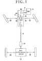
- the power transmitting system for the four-wheel drive vehicle mainly includes a front differential device 6 to which the power of an engine 2 located at a front portion of the vehicle is transmitted from an output shaft 4a of a transmission 4, a speed increasing device (speed changing device) 10 to which the power from the front differential device 6 is transmitted through a propeller shaft 8, and a rear differential device 12 to which the power from the speed increasing device 10 is transmitted.
- the front differential device 6 has a structure well known in the art, and the power from the output shaft 4a of the transmission 4 is transmitted through a plurality of gears 14 and output shafts 16 and 18 in a differential case 6a to left and right front wheel drive shafts 20 and 22, thereby driving front wheels.
- the rear differential device 12 includes a pair of planetary gear sets and a pair of electromagnetic actuators for controlling the engagement of multiplate clutch mechanisms. The electromagnetic actuators are controlled to transmit the power to left and right rear wheel drive shafts 24 and 26, thereby driving rear wheels.
- FIG. 2 is a sectional view of the speed increasing device 10 and the rear differential device 12 located downstream of the speed increasing device 10.
- the speed increasing device 10 includes an input shaft 30 rotatably mounted in a casing 28 and an output shaft (hypoid pinion shaft) 32.
- the speed increasing device 10 further includes an oil pump subassembly 34, a planetary carrier subassembly 38, a lockup clutch 40, and a speed increasing clutch (speed increasing brake) 42.
- the rear differential device 12 located downstream of the speed increasing device 10 has a hypoid pinion gear 44 formed at the rear end of the hypoid pinion shaft 32.
- the hypoid pinion gear 44 is in mesh with a hypoid ring gear 48, and the power from the hypoid ring gear 48 is input to the ring gears of a pair of left and right planetary gear sets 50A and 50B.
- the sun gears of the planetary gear sets 50A and 50B are rotatably mounted on a left rear axle 24 and a right rear axle 26, respectively.
- the planetary carriers of the planetary gear sets 50A and 50B are fixed to the left rear axle 24 and the right rear axle 26, respectively.
- the planetary gear carried by the planetary carrier is in mesh with the sun gear and the ring gear.
- the left and right planetary gear sets 50A and 50B are connected to a pair of left and right clutch mechanism (brake mechanisms) 51 provided to variably control the torque of the respective sun gears.
- Each clutch mechanism 51 includes a wet multiplate clutch (brake) 52 and an electromagnetic actuator 56 for operating the multiplate clutch 52.
- each wet multiplate clutch 52 The clutch plates of each wet multiplate clutch 52 are fixed to a casing 54, and the clutch discs of each wet multiplate clutch 52 are fixed to the sun gear of each of the planetary gear sets 50A and 50B.
- Each electromagnetic actuator 56 is composed of a core (yoke) 58, an exciting coil 60 inserted in the core 58, an armature 62, and a piston 64 connected to the armature 62.
- the exciting coil 60 When a current is passed through the exciting coil 60, the armature 62 is attracted to the core 58 by the coil 60 to thereby generate a thrust.
- the piston 64 integrally connected to the armature 62 pushes the multiplate clutch 52 to thereby generate a clutch torque.
- the sun gears of the planetary gear sets 50A and 50B are fixed to the casing 54, and the drive force of the hypoid pinion shaft 32 is transmitted through the ring gears, the planet gears, and the planetary carriers of the planetary gear sets 50A and 50B to the left and right rear axles 24 and 26.
- the output torques to the left and right rear axles 24 and 26 can be variably controlled.
- the left and right clutch mechanisms 51 are disengaged and the sun gears of the planetary gear sets 50A and 50B therefore idly rotate about the left and right rear axles 24 and 26. Accordingly, the drive force (torque) of the hypoid pinion shaft 32 is not transmitted to the left and right rear axles 24 and 26. In this case, the rear wheels idly rotate and the drive force from the engine is fully transmitted to the front wheels, so that this four-wheel drive vehicle runs in a two-wheel drive mode.
- the lockup clutch 40 is disengaged and the speed increasing clutch 42 is engaged. Accordingly, the rotational speed of the output shaft 32 is increased over that of the input shaft 30.
- the speed increasing rate is about 5%, for example.
- Reference numeral 66 denotes the center of turning
- reference numerals 68L and 68R denote the left and right front wheels, respectively
- reference numerals 70L and 70R denote the left and right rear wheels, respectively. It is assumed that the vehicle is turned counterclockwise about the center 66.
- Reference numeral 72 denotes the locus of the front inner wheel 68L
- reference numeral 74 denotes the locus of the front outer wheel 68R
- reference numeral 76 denotes the average locus of the front wheels.
- Reference numeral 78 denotes the average locus of the rear wheels in the engaged condition of the lockup clutch 40
- reference numeral 80 denotes the locus of the rear outer wheel 70R in the engaged condition of the lockup clutch 40.
- the slip angle of the rear wheels becomes larger (the cornering force becomes larger), so that the locus 80 of the rear outer wheel 70R is larger in radius than the average locus of the rear wheels 78 in the engaged condition of the lockup clutch 40, and the drive force (torque) is not transmitted to the rear outer wheel 70R.
- the speed increasing clutch 42 of the speed increasing device 10 is engaged in this case, thereby increasing the rotational speed of the output shaft 32 by about 5% over the rotational speed of the input shaft 30. Accordingly, the drive force (torque) can be transmitted to the rear outer wheel 70R.
- Reference numeral 82 denotes the locus of the rear outer wheel 70R in the engaged condition of the speed increasing clutch 42.
- the speed increasing clutch 42 is engaged, so that torque transmission to the rear outer wheel is allowed. While the engaging forces of the left and right clutches 52 during left turning are shown in Table 1, the magnitudes of the engaging force of the left clutch 52 may be interchanged with the magnitudes of the engaging force of the right clutch 52 in the case of right turning.
- FIG. 4A shows the condition where the lockup clutch 40 is engaged at acceleration during straight running. In this condition, the torque is transmitted uniformly to the left and right rear axles 24 and 26.
- FIGS. 4A and 4B torque transmission paths are shown by bold lines.
- FIG. 4B shows the condition where the speed increasing clutch 42 is engaged at acceleration during left turning. In this condition, the engaging force of the right clutch 52 is controlled to become larger than the engaging force of the left clutch 52, thereby increasing the torque distribution to the right rear axle 26.
- FIG. 5 is a block diagram of a control system according to the present invention.
- This control system has a feed-forward control section 84, a feedback control section 86, and a speed increase control section 88.
- Engine torque and transmission gear position are input into a block 90 in the feed-forward control section 84 to calculate a tire drive force.
- a vehicle speed detected by a vehicle speed sensor 92 and a steering angle detected by a steering angle sensor 94 are input into a block 96 to calculate an estimated lateral acceleration (estimated lateral G).
- a lateral acceleration (lateral G) detected by a lateral acceleration sensor (lateral G sensor) 98 is input into a block 100 to determine a lateral acceleration (lateral G).
- the lateral G output from the block 100 is corrected by the estimated lateral G output from the block 96 to obtain a control lateral G signal. This correction is made by averaging the lateral G signal and the estimated lateral G signal, for example.
- the control lateral G signal is input into an outer wheel decision block 102 to determine which of the right and left rear wheels is an outer wheel.
- the control lateral G signal is also input into a block 104 to calculate a torque distribution ratio between the front and rear wheels, and is also input into a block 106 to calculate a torque distribution ratio between the right and left wheels.
- An outer wheel signal from the outer wheel decision block 102, a rear wheel distribution ratio signal from the block 104, and a rear outer wheel distribution ratio signal from the block 106 are input into a block 108 to obtain a torque distribution ratio between the rear outer wheel and the rear inner wheel.
- the vehicle speed detected by the vehicle speed sensor 92, the steering angle detected by the steering angle sensor 94, the lateral G detected by the lateral G sensor 98, and a yaw rate detected by a yaw rate sensor 110 are input into a vehicle model block 112 in the feedback control section 86 to calculate a slip angle of the vehicle. Further, a slip angle threshold is calculated by a block 114 according to the vehicle speed detected by the vehicle speed sensor 92 and the lateral G detected by the lateral G sensor 98.
- a rear wheel torque reducing amount is obtained by a block 116 according to a difference between the slip angle and the slip angle threshold, and an outer wheel torque reducing amount is obtained by a block 118 according to this difference.
- the slip angle of the vehicle is greater than a predetermined value, it is determined that the vehicle is in an unstable condition, and the rear wheel distributed torque and the outer wheel distributed torque are reduced to eliminate this unstable condition.
- a left rear wheel torque command value is generated by a block 120 according to the drive torque calculated by the block 90, the left rear wheel torque from the block 108, the rear wheel torque reducing amount from the block 116, and the outer wheel torque reducing amount from the block 118, and the left electromagnetic actuator 56 is controlled by a left clutch control section 122 according to the left rear wheel torque command value generated above.
- a right rear wheel torque command value is generated by a block 124 according to the drive torque calculated by the block 90, the right rear wheel torque from the block 108, the rear wheel torque reducing amount from the block 116, and the outer wheel torque reducing amount from the block 118, and the right electromagnetic actuator 56 is controlled by a right clutch control section 126 according to the right rear wheel torque command value generated above.
- a speed increase threshold is calculated by a block 128 in the speed increase control section 88 according to the vehicle speed detected by the vehicle speed sensor 92.
- the estimated lateral G calculated by the block 96 and the speed increase threshold calculated by the block 128 are compared with each other, and it is determined by a block 130 that a speed increasing condition is to be provided when the estimated lateral G is greater than the speed increase threshold, whereas the lockup condition is to be provided when the estimated lateral G is not greater than the speed increase threshold.
- a speed increase signal or a lockup signal from the block 130 is input into a speed increasing device control section 132 to control the speed increase/lockup of the speed increasing device 10.
- the load on each tire depends on the degree of turning (the magnitude of lateral G) and the magnitude of acceleration. Owing to this tendency, understeer occurs in the vehicle during turning at acceleration, and the running locus of the vehicle is deviated to the outside of turn. As a result, the acceleration performance during turning is limited. It is effective to make the load on each tire uniform in improving this acceleration performance.
- the torque distribution ratio between the front and rear wheels is controlled so that the rear wheel torque is increased with an increase in lateral acceleration (lateral G), and the torque distribution ratio between the right and left wheels is controlled so that the outer wheel torque is increased with an increase in lateral G as shown in FIG. 6.
- the rear wheel torque distribution ratio and the outer wheel torque distribution ratio are increased with an increase in lateral G. Accordingly, understeer occurring during turning at acceleration can be suppressed to thereby allow stable acceleration.
- step 10 the lateral G signal from the lateral G sensor 98 is detected.
- step 11 the estimated lateral G is calculated according to the steering angle detected by the steering angle sensor 94 and the vehicle speed detected by the vehicle speed sensor 92.
- step 12 the lateral G signal is corrected by the estimated lateral G signal to calculate the control lateral G. This correction is performed by averaging the lateral G signal and the estimated lateral G signal, for example.
- an output signal from a lateral G sensor is most general. However, it is known that the output from the lateral G sensor delays from a turning operation by the operator. Further, an actuator for performing the torque distribution generally has delay characteristics. Accordingly, if only the output signal from the lateral G sensor is used, control delay occurs. To suppress such control delay, the estimated lateral G is calculated according to the steering angle and the vehicle speed detected and the output signal from the lateral G sensor is corrected by the estimated lateral G signal obtained above according to this preferred embodiment. Since the steering angle is a turning operation itself by the operator, the estimated lateral G signal can be generated earlier than the output signal from the lateral G sensor. As a result, a control command can be early output to thereby allow quick-response control.
- step 14 it is determined whether or not the vehicle is in an unstable condition. For example, in the case that the slip angle of the vehicle is greater than a predetermined value or the change rate of the slip angle is greater than a predetermined value, it is determined that the vehicle is in an unstable condition.
- predetermined values may be changed according to the condition of a road surface. For example, the smaller the coefficient of friction ( ⁇ ) between a road surface and each tire, the smaller the predetermined values to be set. Accordingly, the unstable condition can be detected earlier and more accurately.
- step 15 the program proceeds to step 15 to obtain a rear wheel torque reducing amount and an outer wheel torque reducing amount and to correct the rear wheel torque and the outer wheel torque according to these reducing amounts, respectively.
- the rear wheel torque reducing amount and the outer wheel torque reducing amount are increased with an increase in estimated slip angle as shown in FIG. 8.
- the unstable condition of the vehicle is corrected in step 15 by making the torque distribution ratio between the front and rear wheels greater on the front wheel side and making the torque distribution ratio between the right and left wheels smaller on the outer wheel side.
- step 16 calculates an actuator control value according to the rear wheel torque and the outer wheel torque.
- This actuator control value includes control values for the right and left electromagnetic actuators 56 and control values for the lockup clutch 40 and the speed increasing clutch 42 of the speed increasing device 10.
- step 17 the right and left electromagnetic actuators 56 are controlled and whether the speed increasing device 10 is to become a lockup condition or a speed increasing condition is controlled according to the above control values.
- the degree of this speed increase is set so that the rotational speed of the output shaft 32 becomes greater by about 5% than the rotational speed of the input shaft 30, for example.
- step 20 A control method for drive force (torque) distribution between the front and rear wheels of the four-wheel drive vehicle will now be described with reference to the flowcharts shown in FIGS. 9 to 11.
- Running condition detection processing will now be described with reference to the flowchart shown in FIG. 9.
- step 20 a turning condition is detected. More specifically, the lateral G signal detected by the lateral G sensor 98 is corrected by the estimated lateral G calculated according to the vehicle speed and the steering angle to calculate the control lateral G.
- step 21 a vehicle speed is detected from the signal from the vehicle speed sensor 92.
- step 22 an accelerator opening is detected.
- step 23 a transmission shift position is detected.
- step 24 a transmission reverse range is detected.
- step 25 a 4WD oil temperature, or an oil temperature of the rear differential device 12 is detected.
- Target rear wheel torque calculation processing will now be described with reference to the flowchart shown in FIG. 10.
- step 30 a rear wheel torque according to the turning condition is calculated.
- step 31 a rear wheel torque correction amount K1 according to the vehicle speed is calculated. In this preferred embodiment, the torque distribution to the rear wheels is decreased with an increase in the vehicle speed by using the correction amount K1 as shown in FIG. 12.
- a rear wheel torque correction amount K2 according to the accelerator opening is calculated.
- the torque distribution to the rear wheels is increased with an increase in the accelerator opening by using the correction amount K2 as shown in FIG. 13.
- a rear wheel torque correction amount K3 according to the transmission shift position is calculated.
- the torque distribution to the rear wheels is decreased by using the correction amount K3 in the case that the transmission shift position is a low-speed position or a high-speed position as shown in FIG. 14.
- a rear wheel torque correction amount K4 according to the reverse range is calculated.
- the torque distribution to the rear wheels is decreased by using the correction amount K4 in the case of reverse running.
- a rear wheel torque correction amount K5 according to the 4WD oil temperature, or the oil temperature of the rear differential device 12 is calculated.
- the torque distribution to the rear wheels is decreased with a decrease in the oil temperature of the rear differential device 12 by using the correction amount K5 as shown in FIG. 15.
- step 36 the rear wheel torque calculated in step 30 is corrected according to the correction amounts K1, K2, K3, K4, and K5 to thereby calculate a target rear wheel torque.
- step 40 of the flowchart showing 4WD control in FIG. 11 an actuator control value is calculated according to the target rear wheel torque.
- step 41 the actuator is controlled according to the actuator control value calculated above. More specifically, the degree of engagement of the right and left electromagnetic actuators 56 is controlled according to the control value to thereby control the torque distribution ratio between the front and rear wheels.
- step 50 a rear outer wheel torque according to the turning condition is calculated. This turning condition is determined according to the lateral G.
- a rear outer wheel torque correction amount K6 according to the vehicle speed is calculated. In this preferred embodiment, the torque distribution to the rear outer wheel is decreased with an increase in the vehicle speed by using the correction amount K6 as shown in FIG. 17.
- a rear outer wheel torque correction amount K7 according to the transmission shift position is calculated.
- the torque distribution to the rear outer wheel is decreased by using the correction amount K7 in the case that the transmission shift position is a low-speed position or a high-speed position as shown in FIG. 18.
- a rear outer wheel torque correction amount K8 according to the reverse range is calculated. In this preferred embodiment, the torque distribution to the rear outer wheel is decreased by using the correction amount K8 in the case of reverse running.
- step 54 a rear outer wheel torque correction amount K9 according to the 4WD oil temperature, or the oil temperature of the rear differential device 12 is calculated.
- the torque distribution to the rear outer wheel is decreased with a decrease in temperature of hydraulic fluid for the rear differential device 12 by using the correction amount K9 as shown in FIG. 19.
- step 55 the rear outer wheel torque calculated in step 50 is corrected according to the correction amounts K6, K7, K8, and K9 to thereby calculate a target rear outer wheel torque.
- step 40 of the flowchart shown in FIG. 11 an actuator control value is next calculated according to the target rear outer wheel torque calculated above, and as in step 41 in FIG. 11, the degree of engagement of the right and left electromagnetic actuators 56 are controlled according to the control value calculated above.
- the lockup/speed increase control for the speed increasing device 10 will now be described.
- the object of the lockup/speed increase control for the speed increasing device 10 is to operate the speed increasing device 10 so that the outer wheel can be driven during turning.
- the lateral G signal is used to quickly and accurately determine the turning condition.
- the lateral G is zero.
- the speed increasing device 10 can be controlled to an increasing speed condition immediately after the vehicle starts turning. For example, when the lateral G signal for the vehicle exceeds the lateral G threshold according to the vehicle speed, the lockup condition or same speed condition of the speed increasing device 10 is changed to the increasing speed condition.
- the speed increasing can be performed before largely driving the outer wheel to thereby ensure a condition where the outer wheel can be driven. Accordingly, a larger drive force can be applied to the outer wheel as compared with the inner wheel, thereby improving the turning performance.
- the lateral G signal can be obtained more quickly during the process of transition from the straight running condition to the turning condition.
- the steering angle is an input itself from the operator, and a delay of motion of the vehicle is added to the actual generation of lateral G.
- it is also effective to partially correct the output signal from the lateral G sensor by using the estimated lateral G signal or to use the average of the lateral G signal and the estimated lateral G signal.
- a speed increase command is generated after the decision of turning. If the speed increasing device 10 is operated immediately according to the speed increase command, the controller is influenced by the noise included in the signal, and a speed increase stop command is generated every time the turning direction changes as in slalom running, causing an increase in frequency of operation of the speed increasing device 10. In order to minimize the noise, shock, etc. due to the operation of the speed increasing device and reduce the frequency of operation of the speed increasing device with a reduced size and weight, the speed increasing device 10 is controlled so that the command to the speed increasing device 10 is not immediately executed, but the command is continued for about one second, for example, prior to performing the actual operation of the device 10.
- FIG. 20 shows the flowchart of change control from the lockup condition (same speed condition) to the increasing speed condition.
- step 60 it is determined whether or not a speed increase command is ON. If the speed increase command is ON, the program proceeds to step 61 to start time measurement by a timer.
- step 62 it is determined whether or not the measured time T is greater than a predetermined value T0.
- step 64 determines the speed increasing operation. Then, the lockup clutch 40 of the speed increasing device 10 is disengaged and the speed increasing clutch 42 is engaged. If the measured time T is less than or equal to the predetermined value TO in step 62, the program proceeds to step 63 to determine whether or not the speed increase command is OFF. If the speed increase command is not OFF, the determination of step 62 is executed again, whereas if the speed increase command is OFF, the determination of step 60 is executed again.
- step 70 it is determined whether or not a lockup command is ON. If the lockup command is ON, the program proceeds to step 71 to start time measurement by a timer. In step 72, it is determined whether or not the measured time T is greater than a predetermined value T0. If T > TO in step 72, the program proceeds to step 74 to determine the lockup operation. Then, the speed increasing clutch 42 of the speed increasing device 10 is disengaged, and the lockup clutch 40 is engaged.
- step 73 determines whether or not the lockup command is OFF. If the lockup command is not OFF, the determination of step 72 is executed again, whereas if the lockup command is OFF, the determination of step 70 is executed again.
- the object of this speed increase control is to improve the maneuverability of the vehicle by driving the outer wheel more than the inner wheel. When the vehicle becomes an unstable condition, there is a case that any particular improvement in the maneuverability is not desired under any circumstances such as counter steer running.
- step 80 it is determined whether or not counter steer is detected. If the counter steer is detected, the program proceeds to step 82 to generate a lockup command, thereby engaging the lockup clutch 40 of the speed increasing device 10.
- step 80 the program proceeds to step 81 to determine whether or not the slip angle ⁇ of the vehicle body is greater than a slip angle threshold ⁇ 0. If the slip angle ⁇ is greater than the threshold ⁇ 0, it is determined that the behavior of the vehicle is unstable, and the program proceeds to step 82 to generate the lockup command, thereby engaging the lockup clutch 40 of the speed increasing device 10 to stabilize the behavior.
- the speed increase control is inhibited to thereby allow a reduction in torque to be input into the speed increasing device 10 and a reduction in frequency of operation of the device 10. Accordingly, this is effective in reducing the weight of the device 10 and in improving the durability of the device 10.
- the speed increase control is inhibited as shown in FIG. 23. That is, when the shift position is a first-speed position, a very large torque is generated. However, since the vehicle speed at the first-speed position is low, the effect by the outer wheel driving cannot be so obtained. Conversely, when the shift position is a fifth-speed position, the vehicle speed is too high and there is a danger that the vehicle is excessively turned. Therefore, the speed increase control is inhibited also in this case. In addition, when the shift position is in a reverse position, an improvement in driving stability cannot be expected and the speed increase control is therefore inhibited.
- the speed increase control is also inhibited to thereby allow a reduction in torque to be input into the speed increasing device 10 and a reduction in frequency of operation of the device 10. Accordingly, the weight of the device 10 can be reduced and the durability of the device 10 can be improved. Further, by controlling the speed increasing device 10 into the lockup condition in the engine brake condition or during braking, a braking force can be applied to the outer wheel, and this is effective also in suppressing oversteer occurring in braking during turning.
- FIG. 24 shows the flowchart of control in the engine brake condition.
- step 90 it is determined whether or not the drive torque is negative, that is, whether or not the vehicle is in the engine brake condition. If the vehicle is in the engine brake condition, the program proceeds to step 91 to generate a lockup command, thereby disengaging the speed increasing clutch 42 of the speed increasing device 10 and engaging the lockup clutch 40.
- FIG. 25 shows the flowchart of control during braking.
- step 100 it is determined whether or not the vehicle is being braked by the operator. If the vehicle is being braked by the operator, the program proceeds to step 101 to generate a lockup command, thereby disengaging the speed increasing clutch 42 of the speed increasing device 10 and engaging the lockup clutch 40.
- the operation of the speed increasing device 10 is relied on the oil pressure of a pump driven by an axle, there is a possibility that an oil pressure required for the speed increasing cannot be obtained at certain low vehicle speeds.
- the control is relied on only the lateral G threshold, a speed increase command is undesirably generated in the stage where a sufficient oil pressure is not obtained, causing a possibility of adverse effects on the speed increasing clutch 42.
- the lockup condition is shifted to the increasing speed condition. Accordingly, even during turning at this vehicle speed or higher, the lockup condition is changed to the increasing speed condition.
- the change to the increasing speed condition is inhibited until the vehicle runs straight at a given vehicle speed (V1) or more during low-speed running at a given vehicle speed (V0) or less. Accordingly, the speed increase control at the vehicle speed V0 or less can be avoided. Further, a rapid change to the increasing speed condition during turning can also be prevented.
- step 110 it is determined whether or not the vehicle speed V is less than the given vehicle speed V0. If the vehicle speed V is less than the given vehicle speed V0, the program proceeds to step 111 to inhibit the change to the increasing speed condition. Thereafter, the vehicle continues to run. In step 112, it is determined whether or not the vehicle speed V is greater than V1 which is greater than V0 and the lateral G is less than G0. If the answer in step 112 is YES, the program proceeds to step 113 to permit the change to the increasing speed condition. The value GO in step 112 is set to about 0.1 G. Further, the determination in step 112 is to determine whether or not the vehicle is running straight at a vehicle speed greater than V1.
- the control method of the present invention is also applicable to a vehicle such that the power from a driving power source such as an engine is directly transmitted to the rear wheels, that the transmission of the power to the right and left rear wheels can be controlled by a clutch or the like, and that the power can also be transmitted to the front wheels by a clutch or the like.
- the vehicle may be of such a type that the rear wheels are normally increased in rotational speed.
- a drive force control method for a four-wheel drive vehicle having front wheels as main drive wheels always connected to a driving source, rear wheels as auxiliary drive wheels whose drive torque is adjustable, and a mechanism capable of adjusting a torque distribution ratio between the front wheels and the rear wheels so that the torque distribution ratio of the rear wheels to the front wheels is increased in turning and also capable of adjusting a torque distribution ratio between the right and left rear wheels in turning.
- the drive force control method includes the steps of detecting a vehicle speed, and gently decreasing the torque distribution ratio of a turning outer wheel to a turning inner wheel with an increase in the vehicle speed. When the transmission shift position is a low-speed position or a high-speed position or the vehicle is in reverse running, the torque distribution ratio of the turning outer wheel to the turning inner wheel is decreased.
Landscapes
- Engineering & Computer Science (AREA)
- Mechanical Engineering (AREA)
- Chemical & Material Sciences (AREA)
- Combustion & Propulsion (AREA)
- Transportation (AREA)
- General Engineering & Computer Science (AREA)
- Arrangement And Driving Of Transmission Devices (AREA)
Abstract
Description


- In the case of right turn, the magnitudes in the element (3) and the magnitudes in the element (4) are interchanged.
- Conditions for turning (lockup):
- The vehicle speed is less than 30 km/h or greater than 120 km/h.
- The lateral G is less than 0.075 G.
- The vehicle speed is 30 to 120 km/h, and the lateral G is not less than 0.075 G.
Claims (9)
- A drive force control method for a four-wheel drive vehicle having main drive wheels connected to a driving source, auxiliary drive wheels whose drive torque is adjustable, and a mechanism capable of adjusting a torque distribution ratio between said main drive wheels and said auxiliary drive wheels so that the torque distribution ratio of said auxiliary drive wheels to said main drive wheels is increased in turning and also capable of adjusting a torque distribution ratio between said right and left auxiliary drive wheels in turning, said drive force control method comprising the steps of:detecting a vehicle speed; andgradually decreasing the torque distribution ratio of a turning outer wheel as one of said right and left auxiliary drive wheels to a turning inner wheel as the other with an increase in said vehicle speed.
- The drive force control method for a four-wheel drive vehicle according to claim 1, further comprising the step of decreasing the torque distribution ratio of said turning outer wheel to said turning inner wheel in a low-speed position or a high-speed position as a transmission shift position.
- The drive force control method for a four-wheel drive vehicle according to claim 1, further comprising the step of decreasing the torque distribution ratio of said turning outer wheel to said turning inner wheel in reverse running.
- The drive force control method for a four-wheel drive vehicle according to claim 1, further comprising the step of decreasing the torque distribution ratio of said turning outer wheel to said turning inner wheel with a decrease in temperature of hydraulic fluid for a differential device for said auxiliary drive wheels.
- A drive force control method for a four-wheel drive vehicle having main drive wheels connected to a driving source, auxiliary drive wheels whose drive torque is adjustable, and a mechanism capable of adjusting a torque distribution ratio between said main drive wheels and said rear wheels so that the torque distribution ratio of said auxiliary drive wheels to said main drive wheels is increased in turning, said drive force control method comprising the steps of:detecting a vehicle speed; andgradually decreasing the torque distribution ratio of said auxiliary drive wheels to said main drive wheels with an increase in said vehicle speed.
- The drive force control method for a four-wheel drive vehicle according to claim 5, further comprising the step of increasing the torque distribution ratio of said auxiliary drive wheels to said main drive wheels with an increase in accelerator opening.
- The drive force control method for a four-wheel drive vehicle according to claim 5, further comprising the step of decreasing the torque distribution ratio of said auxiliary drive wheels to said main drive wheels in a low-speed position or a high-speed position as a transmission shift position.
- The drive force control method for a four-wheel drive vehicle according to any one of claim 5, further comprising the step of decreasing the torque distribution ratio of said auxiliary drive wheels to said main drive wheels in reverse running.
- The drive force control method for a four-wheel drive vehicle according to any one of claim 5, further comprising the step of decreasing the torque distribution ratio of said auxiliary drive wheels to said main drive wheels with a decrease in temperature of hydraulic fluid for a differential device for said auxiliary drive wheels.
Applications Claiming Priority (8)
| Application Number | Priority Date | Filing Date | Title |
|---|---|---|---|
| JP2004105026A JP4554252B2 (en) | 2004-03-31 | 2004-03-31 | Control method for four-wheel drive vehicle |
| JP2004105023 | 2004-03-31 | ||
| JP2004105024A JP2005289161A (en) | 2004-03-31 | 2004-03-31 | Driving force control method of 4-wheel drive vehicle |
| JP2004105026 | 2004-03-31 | ||
| JP2004105024 | 2004-03-31 | ||
| JP2004105025 | 2004-03-31 | ||
| JP2004105023A JP4267495B2 (en) | 2004-03-31 | 2004-03-31 | Driving force control method for four-wheel drive vehicle |
| JP2004105025A JP4298564B2 (en) | 2004-03-31 | 2004-03-31 | Driving force control method for four-wheel drive vehicle |
Publications (3)
| Publication Number | Publication Date |
|---|---|
| EP1582391A2 true EP1582391A2 (en) | 2005-10-05 |
| EP1582391A3 EP1582391A3 (en) | 2006-07-19 |
| EP1582391B1 EP1582391B1 (en) | 2009-01-14 |
Family
ID=34891242
Family Applications (3)
| Application Number | Title | Priority Date | Filing Date |
|---|---|---|---|
| EP05007101A Ceased EP1582391B1 (en) | 2004-03-31 | 2005-03-31 | Drive force control method for four-wheel drive vehicle |
| EP05007114A Ceased EP1582392B1 (en) | 2004-03-31 | 2005-03-31 | Control method for four-wheel drive vehicle |
| EP05007100A Ceased EP1582390B1 (en) | 2004-03-31 | 2005-03-31 | Drive force control method for four-wheel drive vehicle |
Family Applications After (2)
| Application Number | Title | Priority Date | Filing Date |
|---|---|---|---|
| EP05007114A Ceased EP1582392B1 (en) | 2004-03-31 | 2005-03-31 | Control method for four-wheel drive vehicle |
| EP05007100A Ceased EP1582390B1 (en) | 2004-03-31 | 2005-03-31 | Drive force control method for four-wheel drive vehicle |
Country Status (2)
| Country | Link |
|---|---|
| EP (3) | EP1582391B1 (en) |
| DE (3) | DE602005013139D1 (en) |
Families Citing this family (4)
| Publication number | Priority date | Publication date | Assignee | Title |
|---|---|---|---|---|
| US7600598B2 (en) | 2006-05-05 | 2009-10-13 | Ford Global Technologies, Llc | Biasing drive torque to a secondary axle in a motor vehicle powertrain |
| JP4894609B2 (en) * | 2007-05-10 | 2012-03-14 | トヨタ自動車株式会社 | Vehicle driving force control device |
| JP5299368B2 (en) * | 2010-07-09 | 2013-09-25 | 日産自動車株式会社 | Vehicle left and right wheel driving force distribution control device |
| KR102530684B1 (en) * | 2018-05-04 | 2023-05-11 | 현대자동차주식회사 | Control method for implementation of drift of vehicle |
Citations (3)
| Publication number | Priority date | Publication date | Assignee | Title |
|---|---|---|---|---|
| EP0311140A2 (en) | 1987-10-09 | 1989-04-12 | Nissan Motor Co., Ltd. | Active control for distributing driving force over four-wheels of four-wheel drive vehicle |
| US20020153770A1 (en) | 2001-04-24 | 2002-10-24 | Fuji Jukogyo Kabushiki Kaisha | Vehicle behavior control apparatus |
| US20040058776A1 (en) | 2002-09-25 | 2004-03-25 | Honda Giken Kogyo Kabushiki Kaisha | Power transfer apparatus |
Family Cites Families (17)
| Publication number | Priority date | Publication date | Assignee | Title |
|---|---|---|---|---|
| JPS60226326A (en) * | 1984-04-23 | 1985-11-11 | Daihatsu Motor Co Ltd | Four wheel drive vehicle |
| JPS61169326A (en) * | 1985-01-21 | 1986-07-31 | Nissan Motor Co Ltd | Driving force distribution controller for 4 wheel drive car |
| DE3630754A1 (en) * | 1986-09-10 | 1988-03-24 | Opel Adam Ag | Motor vehicle with all-wheel drive |
| JPH0764219B2 (en) * | 1988-01-18 | 1995-07-12 | 本田技研工業株式会社 | Front and rear wheel drive system |
| JPH0761779B2 (en) * | 1988-03-14 | 1995-07-05 | 本田技研工業株式会社 | Front and rear wheel drive system |
| JP2683655B2 (en) * | 1988-03-28 | 1997-12-03 | マツダ株式会社 | Torque distribution device for four-wheel drive vehicle |
| US4989686A (en) * | 1988-07-07 | 1991-02-05 | Borg-Warner Automotive, Inc. | System for controlling torque transmission in a four wheel drive vehicle |
| JP2693204B2 (en) * | 1989-01-31 | 1997-12-24 | マツダ株式会社 | Torque distribution control device for four-wheel drive vehicle |
| JP3221873B2 (en) | 1990-04-20 | 2001-10-22 | マツダ株式会社 | Torque distribution control device for four-wheel drive vehicle |
| JPH0764219A (en) | 1993-08-24 | 1995-03-10 | Fuji Photo Film Co Ltd | Silver halide photographic sensitive material and forming method of radiograph using the same |
| JPH0761779A (en) | 1993-08-31 | 1995-03-07 | Mitsubishi Heavy Ind Ltd | Fuzzy control type mooring machine |
| JP3275563B2 (en) * | 1994-09-21 | 2002-04-15 | 日産自動車株式会社 | Vehicle four-wheel drive control device |
| US6007453A (en) * | 1996-11-07 | 1999-12-28 | Honda Giken Kogyo Kabushiki Kaisha | Torque splitting device using hydraulic clutches |
| JP3340038B2 (en) * | 1996-11-14 | 2002-10-28 | 本田技研工業株式会社 | Left and right wheel driving force distribution device |
| JP2002278836A (en) | 2001-03-15 | 2002-09-27 | Oki Electric Ind Co Ltd | Cache memory |
| JP4263448B2 (en) * | 2002-09-24 | 2009-05-13 | 富士重工業株式会社 | Vehicle differential limiting control device |
| US6752233B1 (en) * | 2003-02-11 | 2004-06-22 | General Motors Corporation | Selectable overspeed secondary drive module |
-
2005
- 2005-03-31 EP EP05007101A patent/EP1582391B1/en not_active Ceased
- 2005-03-31 DE DE602005013139T patent/DE602005013139D1/en active Active
- 2005-03-31 DE DE602005012335T patent/DE602005012335D1/en active Active
- 2005-03-31 EP EP05007114A patent/EP1582392B1/en not_active Ceased
- 2005-03-31 DE DE602005016982T patent/DE602005016982D1/en active Active
- 2005-03-31 EP EP05007100A patent/EP1582390B1/en not_active Ceased
Patent Citations (3)
| Publication number | Priority date | Publication date | Assignee | Title |
|---|---|---|---|---|
| EP0311140A2 (en) | 1987-10-09 | 1989-04-12 | Nissan Motor Co., Ltd. | Active control for distributing driving force over four-wheels of four-wheel drive vehicle |
| US20020153770A1 (en) | 2001-04-24 | 2002-10-24 | Fuji Jukogyo Kabushiki Kaisha | Vehicle behavior control apparatus |
| US20040058776A1 (en) | 2002-09-25 | 2004-03-25 | Honda Giken Kogyo Kabushiki Kaisha | Power transfer apparatus |
Also Published As
| Publication number | Publication date |
|---|---|
| DE602005013139D1 (en) | 2009-04-23 |
| EP1582391B1 (en) | 2009-01-14 |
| EP1582392A2 (en) | 2005-10-05 |
| DE602005012335D1 (en) | 2009-03-05 |
| EP1582390B1 (en) | 2009-10-07 |
| EP1582390A3 (en) | 2006-07-19 |
| EP1582392B1 (en) | 2009-03-11 |
| EP1582390A2 (en) | 2005-10-05 |
| EP1582392A3 (en) | 2006-09-20 |
| EP1582391A3 (en) | 2006-07-19 |
| DE602005016982D1 (en) | 2009-11-19 |
Similar Documents
| Publication | Publication Date | Title |
|---|---|---|
| US7264077B2 (en) | Drive force control method for four-wheel drive vehicle | |
| US7715968B2 (en) | Control method for four-wheel drive vehicle | |
| US7374255B2 (en) | Control method for four-wheel drive vehicle | |
| US7383910B2 (en) | Drive force control method for four-wheel drive vehicle | |
| CN108146240B (en) | Torque distribution control device for vehicle | |
| US8948991B2 (en) | Left-right wheel drive force distribution control apparatus for a vehicle | |
| JPH0616061A (en) | Four wheel drive control device | |
| US7610980B2 (en) | Drive force control method for four-wheel drive vehicle | |
| EP1627763B1 (en) | Control method for four-wheel drive vehicle | |
| US20130103228A1 (en) | Left-right wheel drive force distribution control apparatus for a vehicle | |
| US8694220B2 (en) | Left-right wheel drive force distribution control apparatus for a vehicle | |
| US9103426B2 (en) | Left-right wheel drive force distribution control apparatus for a vehicle | |
| EP1582391B1 (en) | Drive force control method for four-wheel drive vehicle | |
| JP2005289161A (en) | Driving force control method of 4-wheel drive vehicle | |
| JP2018167806A (en) | Torque distribution control device of four-wheel drive vehicle | |
| JP4298564B2 (en) | Driving force control method for four-wheel drive vehicle | |
| JP2612718B2 (en) | Torque split control device for four-wheel drive vehicle | |
| JP2615084B2 (en) | Torque split control device for four-wheel drive vehicle | |
| WO2012005265A1 (en) | Device for controlling torque distribution to left and right wheels on a vehicle | |
| JP2005289162A5 (en) | ||
| JP4923126B2 (en) | Control method for four-wheel drive vehicle | |
| JP2615083B2 (en) | Torque split control device for four-wheel drive vehicle | |
| JP2018091435A (en) | Vehicle torque distribution control device |
Legal Events
| Date | Code | Title | Description |
|---|---|---|---|
| PUAI | Public reference made under article 153(3) epc to a published international application that has entered the european phase |
Free format text: ORIGINAL CODE: 0009012 |
|
| AK | Designated contracting states |
Kind code of ref document: A2 Designated state(s): AT BE BG CH CY CZ DE DK EE ES FI FR GB GR HU IE IS IT LI LT LU MC NL PL PT RO SE SI SK TR |
|
| AX | Request for extension of the european patent |
Extension state: AL BA HR LV MK YU |
|
| PUAL | Search report despatched |
Free format text: ORIGINAL CODE: 0009013 |
|
| AK | Designated contracting states |
Kind code of ref document: A3 Designated state(s): AT BE BG CH CY CZ DE DK EE ES FI FR GB GR HU IE IS IT LI LT LU MC NL PL PT RO SE SI SK TR |
|
| AX | Request for extension of the european patent |
Extension state: AL BA HR LV MK YU |
|
| RIC1 | Information provided on ipc code assigned before grant |
Ipc: B60K 17/35 20060101ALI20060615BHEP Ipc: B60K 23/08 20060101AFI20050706BHEP |
|
| 17P | Request for examination filed |
Effective date: 20060906 |
|
| 17Q | First examination report despatched |
Effective date: 20061107 |
|
| AKX | Designation fees paid |
Designated state(s): DE GB |
|
| GRAP | Despatch of communication of intention to grant a patent |
Free format text: ORIGINAL CODE: EPIDOSNIGR1 |
|
| GRAS | Grant fee paid |
Free format text: ORIGINAL CODE: EPIDOSNIGR3 |
|
| GRAA | (expected) grant |
Free format text: ORIGINAL CODE: 0009210 |
|
| AK | Designated contracting states |
Kind code of ref document: B1 Designated state(s): DE GB |
|
| REG | Reference to a national code |
Ref country code: GB Ref legal event code: FG4D |
|
| REF | Corresponds to: |
Ref document number: 602005012335 Country of ref document: DE Date of ref document: 20090305 Kind code of ref document: P |
|
| PLBE | No opposition filed within time limit |
Free format text: ORIGINAL CODE: 0009261 |
|
| STAA | Information on the status of an ep patent application or granted ep patent |
Free format text: STATUS: NO OPPOSITION FILED WITHIN TIME LIMIT |
|
| 26N | No opposition filed |
Effective date: 20091015 |
|
| REG | Reference to a national code |
Ref country code: DE Ref legal event code: R084 Ref document number: 602005012335 Country of ref document: DE |
|
| REG | Reference to a national code |
Ref country code: GB Ref legal event code: 746 Effective date: 20141114 |
|
| REG | Reference to a national code |
Ref country code: DE Ref legal event code: R084 Ref document number: 602005012335 Country of ref document: DE Effective date: 20141120 |
|
| PGFP | Annual fee paid to national office [announced via postgrant information from national office to epo] |
Ref country code: GB Payment date: 20160330 Year of fee payment: 12 |
|
| PGFP | Annual fee paid to national office [announced via postgrant information from national office to epo] |
Ref country code: DE Payment date: 20170329 Year of fee payment: 13 |
|
| GBPC | Gb: european patent ceased through non-payment of renewal fee |
Effective date: 20170331 |
|
| PG25 | Lapsed in a contracting state [announced via postgrant information from national office to epo] |
Ref country code: GB Free format text: LAPSE BECAUSE OF NON-PAYMENT OF DUE FEES Effective date: 20170331 |
|
| REG | Reference to a national code |
Ref country code: DE Ref legal event code: R119 Ref document number: 602005012335 Country of ref document: DE |
|
| PG25 | Lapsed in a contracting state [announced via postgrant information from national office to epo] |
Ref country code: DE Free format text: LAPSE BECAUSE OF NON-PAYMENT OF DUE FEES Effective date: 20181002 |