EP1582356A2 - Cap for ink jet head - Google Patents
Cap for ink jet head Download PDFInfo
- Publication number
- EP1582356A2 EP1582356A2 EP05251725A EP05251725A EP1582356A2 EP 1582356 A2 EP1582356 A2 EP 1582356A2 EP 05251725 A EP05251725 A EP 05251725A EP 05251725 A EP05251725 A EP 05251725A EP 1582356 A2 EP1582356 A2 EP 1582356A2
- Authority
- EP
- European Patent Office
- Prior art keywords
- cap
- capping
- face
- ink jet
- detachment preventing
- Prior art date
- Legal status (The legal status is an assumption and is not a legal conclusion. Google has not performed a legal analysis and makes no representation as to the accuracy of the status listed.)
- Granted
Links
- 238000007789 sealing Methods 0.000 claims abstract description 17
- 238000007599 discharging Methods 0.000 claims description 38
- 239000000463 material Substances 0.000 description 9
- 238000007639 printing Methods 0.000 description 6
- 230000006835 compression Effects 0.000 description 3
- 238000007906 compression Methods 0.000 description 3
- 238000001746 injection moulding Methods 0.000 description 3
- 238000000465 moulding Methods 0.000 description 3
- 229920003002 synthetic resin Polymers 0.000 description 3
- 239000000057 synthetic resin Substances 0.000 description 3
- 238000005452 bending Methods 0.000 description 2
- 238000001035 drying Methods 0.000 description 2
- 238000000034 method Methods 0.000 description 2
- 239000004642 Polyimide Substances 0.000 description 1
- 239000000853 adhesive Substances 0.000 description 1
- 230000001070 adhesive effect Effects 0.000 description 1
- 238000006073 displacement reaction Methods 0.000 description 1
- 238000005516 engineering process Methods 0.000 description 1
- 239000002184 metal Substances 0.000 description 1
- 229920000728 polyester Polymers 0.000 description 1
- 229920001721 polyimide Polymers 0.000 description 1
- 238000010926 purge Methods 0.000 description 1
Images




Classifications
-
- B—PERFORMING OPERATIONS; TRANSPORTING
- B41—PRINTING; LINING MACHINES; TYPEWRITERS; STAMPS
- B41J—TYPEWRITERS; SELECTIVE PRINTING MECHANISMS, i.e. MECHANISMS PRINTING OTHERWISE THAN FROM A FORME; CORRECTION OF TYPOGRAPHICAL ERRORS
- B41J2/00—Typewriters or selective printing mechanisms characterised by the printing or marking process for which they are designed
- B41J2/005—Typewriters or selective printing mechanisms characterised by the printing or marking process for which they are designed characterised by bringing liquid or particles selectively into contact with a printing material
- B41J2/01—Ink jet
- B41J2/135—Nozzles
- B41J2/165—Prevention or detection of nozzle clogging, e.g. cleaning, capping or moistening for nozzles
- B41J2/16505—Caps, spittoons or covers for cleaning or preventing drying out
- B41J2/16508—Caps, spittoons or covers for cleaning or preventing drying out connected with the printer frame
Definitions
- the present invention relates to a cap for an ink jet head mounted in an ink jet printer.
- An ink jet head mounted in an ink jet printer is provided with a nozzle for discharging ink. Since the nozzle is exposed to the atmosphere, there is a risk that when no ink is discharged for a long period, ink within the nozzle may dry out and block the nozzle.
- the nozzle is formed on an ink discharging face.
- the ink jet printer is provided with a cap that fits tightly with the ink discharging face, thus isolating the ink discharging face from the atmosphere. Covering the ink discharging face with the cap prevents ink within the nozzle from drying out.
- a cap for an ink jet head is set forth in Japanese Laid-Open Patent Application Publication 2001-253080.
- a cap is formed with a sheet member and a capping member provided on a surface of the sheet member.
- the capping member is capable of fitting tightly with an ink discharging face.
- the cap is configured such that it can move between a location where it fits tightly with the ink discharging face and a location where it is distant from the ink discharging face.
- the capping member There is a risk, with the conventional cap, of the capping member becoming detached from the sheet member.
- the cap is configured such that it is moved between the location where the cap fits tightly with the ink discharging face and the location where the cap is distant from the ink discharging face by means of a belt, a wire, or the like, which is wound across a plurality of pulleys, the pulleys alter the direction of movement of the cap. Since the cap is bent when turning around the pulley, the capping member can readily peel away from the sheet member.
- the invention provides a cap for an ink jet head, the cap being improved such that the capping member does not readily become detached from the sheet member.
- a cap of an embodiment of the present invention has a sheet member, a capping member, a detachment preventing member, and a linking member.
- the capping member is provided on one face of the sheet member, and the detachment preventing member is provided on the other face of the sheet member.
- the capping member and the detachment preventing member are linked by the linking member that passes through the sheet member.
- the capping member is supported, by means of the linking member and the detachment preventing member, from the face at the opposite side of the sheet member. Consequently, the capping member does not readily become detached from the sheet member.
- an ink jet printer 1 is provided with a total of eight line type ink jet heads 2.
- Two ink jet heads 2K discharge black ink
- two ink jet heads 2M discharge magenta ink
- two ink jet heads 2C discharge cyan ink
- two ink jet heads 2Y discharge yellow ink.
- the ink jet printer 1 is also provided with a delivery unit 3 that delivers paper in the leftwards direction of FIG. 1.
- the eight ink jet heads 2 are aligned in a left-right direction of FIG. 1 (along the direction of delivery of the paper).
- An ink discharging face 2a is formed at a lower face of each ink jet head 2.
- a plurality of holes 2b is formed in each ink discharge face 2a of each ink jet head 2.
- Each hole 2b works as a nozzle for discharging ink.
- the plurality of the nozzles 2b is divided into four groups, and the nozzles 2b of each group are distributed within a trapezoid area. Four trapezoid areas are arranged in an inner region of the ink discharge face 2a, and no nozzles 2b is arranged in an outer boundary region of the ink discharge face 2a.
- a later described lip member 21b will fits tightly with the outer boundary region having no nozzles 2b for sealing nozzles 2b from the atmosphere.
- a paper feed tray (not shown) is present at a right side of the ink jet heads 2, and a paper discharge tray (not shown) is present at a left side of the ink jet heads 2.
- the delivery unit 3 takes paper from the paper feed tray, passes the paper below the ink jet heads 2, and sends it to the paper discharge tray. Ink is discharged from the ink jet heads 2, and printing of the paper passing below the ink jet heads 2 is thus performed.
- Both ink jet heads (2K, 2M, 2C, and 2Y) that discharge identically colored ink are adjacent in the direction of delivery of the paper.
- Each ink jet head 2 extends in a direction orthogonal to the page of FIG. 1, and extends for a length equivalent to approximately half the width of the paper.
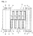
- Both ink jet heads discharging identically colored ink are disposed in locations having displacement therebetween in a direction orthogonal to the page of FIG. 1. As shown in FIG. 3, both ink jet heads 2 discharging identically colored ink are disposed such that end parts thereof overlap when viewed from a direction orthogonal to the paper. Both ink jet heads 2 discharging identically colored ink are used for printing the paper. This allows the entire width of the paper passing below the ink jet heads 2 to be printed at the same time. The two ink jet heads 2 discharging identically colored ink have no space therebetween which would cause a blank area in the printing.
- the delivery unit 3 is provided with two rollers 11 and 12 supported in a manner allowing rotation in a main body frame 10, a continuous carrier belt 13 wound across the rollers 11 and 12, and a belt receiving unit 14 that engages with the carrier belt 13 from below.
- the belt receiving unit 14 prevents the carrier belt 13 from bending downwards between the rollers 11 and 12.
- the belt receiving unit 14 thus enables the carrier belt 13 to move horizontally.
- the delivery unit 3 does not only deliver paper, but is also provided with a cap 15 for covering the ink discharging faces 2a of the ink jet heads 2, and with a mechanism for moving this cap 15.
- the belt receiving unit 14 has a base 17 formed in a fixed manner in the main body frame 10, and has a belt receiving member 19 supported by the base 17 via a plurality of compression springs 18.
- the carrier belt 13 slides along an upper face of the belt receiving member 19.
- the belt receiving unit 14 supports the carrier belt 13 from below. Further, as will be described in detail later, when the cap 15 has been mounted below the ink jet heads 2, the energizing force of the compression springs 18 of the belt receiving unit 14 presses the cap 15 against the ink discharging faces 2a of the ink jet heads 2 via the carrier belt 13.
- the cap 15 fits tightly with the ink discharging faces 2a of the ink jet heads 2 to prevent ink in the nozzles 2b of the ink jet heads 2 from drying out, and to recover ink discharged from the nozzles 2b during a purging process.
- the cap 15 has a sheet member 20 and eight capping portions 21.
- the capping portions 21 are disposed on one face of the sheet member 20 and each of capping portions 21 can fit tightly with each of the ink discharging faces 2a of each of the ink jet heads 2.
- the cap 15 has a detachment preventing member 23 provided at the other face of the sheet member 20 and linking members 32.
- the linking members 32 pass through the sheet member 20 and link the capping portions 21 and the detachment preventing member 23.
- the sheet member 20 is formed from a flexible material with a low elongation percentage, such as polyimide, polyester, or the like.
- the sheet member 20 does not allow the air to pass through.
- the sheet member 20 is formed in a sheet shape and, from a plan view, has a rectangular shape.
- the eight capping portions 21 formed on one face of the sheet member 20 are disposed in locations corresponding to the eight ink jet heads 2.
- the capping member of the embodiment includes eight capping portions 21.
- each capping portion 21 is provided with a base member 21a and a lip member 21b.
- Each base member 21a is formed by a portion of the sheet member 20, and has a plane rectangular shape slightly larger than a plane shape of a region where the nozzles 2b are distributed on the ink discharging face 2a.
- the lip member 21b surrounds the circumference of the base member 21a in a frame shape that corresponds to the outer boundary region of the ink discharge face 2a.
- the lip member 21b rises above the sheet member 20.
- the lip members 21b are molded from soft synthetic resin, and adhered to the sheet member 20.
- the lip member 21b is softer than the sheet member 20 and easily deformable due its elasticity.
- the lip member 21b does not allow the air to pass through.
- the material of the sheet member 20 is selected to be suitable to the sheet member 20, and the material of the lip member 21b is selected to be suitable to the lip member 21b.
- the materials of the sheet member 20 and the lip sheet member 21b are different.
- the detachment preventing member 23 is provided on the other face of the sheet member 20.
- the detachment preventing member 23 includes eight detachment preventing portions.
- the shape and location of each of the detachment preventing portions correspond to those of each of the capping portions 21.
- the eight detachment preventing portions are mutually connected to form the single common detachment preventing member 23. That is, a total of eight detachment preventing portions are all linked integrally.
- the capping portions 21 formed on one face of the sheet member 20, and the detachment preventing member 23 formed on the other face of the sheet member 20, are linked by the linking members 32 that pass through the sheet member 20.
- a plurality of holes 20a (see FIGS. 5 and 6) is formed in the sheet member 20 in regions that, from a plan view, overlap with the lip members 21b.
- the linking members 32 pass through these holes 20a to link the capping portions 21 and the detachment preventing member 23.
- the holes 20a should rightfully be shown by a dotted line. However, a solid line has been drawn for the sake of clarity.
- the lip members 21b, the detachment preventing member 23, and the linking portions 32 are molded integrally by means of injection molding.
- the detachment preventing member 23 for the eight capping portions 21 is linked integrally, and the face is substantially flat.
- the cap 15 When the cap 15 is moved between a sealing location (to be described: see FIG. 8) and a retreated location (see FIG. 1), the cap 15 bends during this movement. Simultaneously, as shown in FIG. 2, the detachment preventing member 23 makes contact with the guide member 16. Since the detachment preventing member 23 is formed integrally and the surface thereof is substantially flat, the cap 15 can be moved smoothly across the guide member 16.
- a pair of sheet supporting bars 22 is formed at both end portions of the sheet member 20 in a left-right direction relative to FIG. 3 (the direction of delivery of the paper).
- the sheet supporting bars 22 are formed from metal and have a narrow line shape.
- the delivery unit 3 is provided with belts 25.
- the belts 25 are formed at a closer side and a further side (relative to the page of FIG. 1) of the paper carrier belt 13.
- One end of the sheet supporting bar 22 is linked with the belt 25 of the closer side via a connecting member 24 and the other end part of the sheet supporting bar 22 is linked with the belt 25 of the further side via the connecting member 24.
- the belts 25 are wound across four pulleys 26, 27, 28, and 29 and an outer circumference of the guide member 16.
- the pulleys 26, 27, 28, and 29 are formed at a left side portion of the main body frame 10, and the guide member 16, which is semicircular when viewed frontally, is formed at the right side of driven roller 12.
- the pulley 26 is caused to rotate by a motor (not shown) linked with this pulley 26, the belts 25 on both sides rotate, and the cap 15 moves therewith.
- the cap 15 moves along an outer side of the carrier belt 13.
- the cap 15 is moved by the belts 25 between the sealing location (see FIG. 8) and the retreated location (see FIG. 1).
- the cap 15 is located between the ink discharge faces 2a of the ink jet heads 2, and the carrier belt 13. As shown in FIG. 8, the cap 15 is located above the carrier belt 13. In FIG. 8, the ink jet heads 2 have been omitted and only the delivery unit 3 is shown so that the location of the cap 15 is shown more clearly.
- the capping portions of the capping member 21 face the ink discharging faces 2a of the ink jet heads 2, and can seal the ink jet nozzles 2b distributed on the ink discharging faces 2a.
- the cap 15 is located below the carrier belt 13 (see FIG. 1).
- the carrier belt 13 directly faces the ink discharging faces 2a of the ink jet heads 2 via the printing paper, so that ink discharged from the ink jet heads 2 is injected onto the printing paper, and printing of the paper passing below the ink jet heads 2 is thus performed.
- the main body frame 10 of the delivery unit 3 can be swung along a vertical plane, with a rotational axis 11a of the driving roller 11 as the center, by means of a swinging device (not shown). Further, the main body frame 10 of the delivery unit 3 can be raised and lowered relative to the ink jet heads 2 by means of a raising and lowering mechanism (not shown). In the case where the ink discharging faces 2a are to be sealed by the cap 15, the main body frame 10 is first rotated by the swinging device in a clockwise direction relative to FIG. 1, with the rotational axis 11a as the center, until the delivery unit 3 has been swung to the location in FIG. 7. In this state, the pulley 26 is rotated.
- FIG. 7 shows a state where the cap 15 is being moved from the retreated position to the sealing position.
- the cap 15 is bent while moving from the retreated position to the sealing position.
- the cap 15 reaches the sealing position as shown in FIG. 8.
- the main body frame 10 is rotated by the swinging device in an counterclockwise direction relative to FIG. 1, with the rotational axis 11a as the center, until the delivery unit 3 has been swung to the location in FIG. 8.
- the capping members 21 face the ink jet heads 2.
- the main body frame 10 is moved upwards, relative to the ink jet heads 2, by the raising and lowering mechanism (not shown).
- the energizing force of the compression springs 18 of the belt receiving unit 14 presses the capping members 21 of the cap 15, located on the upper side of the carrier belt 13, against the ink jet heads 2.
- the ink discharging nozzles 2b at the ink discharging faces 2a are thus sealed by the capping members 21.
- the cap 15 When the cap 15 is to be moved between the sealing location (see FIG. 8), in which the capping members 21 face upwards (facing the ink jet heads 2) and the retreated location (see FIG. 1), in which the capping members 21 face the opposite side from the ink jet heads 2, the cap 15 slides on the outer circumference part of the guide member 16. At this juncture, the direction of movement of the cap 15 changes from horizontal to vertical, thus necessitating a bending of the cap 15. If the lip members 21b of the capping members 21 were bonded to the sheet member 20 only by means of adhesive or the like, there would be considerable risk of the lip members 21b becoming detached from the sheet member 20 when the cap 15 bends.
- the lip members 21b would also readily become detached when the lip members 21b are removed from the ink discharging faces 2a of the ink jet heads 2.
- the capping members 21 (the lip members 21b) are linked with the detachment preventing member 23 located on the opposite face of the sheet member 20 relative to the capping members 21, and the sheet member 20 is held between these two parts. This prevents the capping members 21 from becoming detached from the sheet member 20. There may be no risk of the lip members 21b being detached from the sheet member 20, if the lip members 21b and the sheet member 20 are integrally formed. However, the sheet member 20 must be formed from a material having a low elongation percentage.
- the sheet member 20 If the sheet member 20 is elongated, the sheet member 20 can not be moved by the rotation of the pulley 26. On the contrary, the lip members 21b must be formed from a soft rubber-like material. In the embodiment, the sheet member 20 made from the suitable material for the sheet member 20 and the lip member 21b made from the suitable material for the lip member 21b, the materials being different, can be held tightly.
- a capping member 31 may have a base member 31a that overlaps with the sheet member 20, and a lip member 31b that surrounds a circumference of the base member 31a, with the base member 31a and the lip member 31b being molded integrally from soft synthetic resin. If the capping member 31 has this structure, the capping member 31 fits more tightly to the ink discharging face 2a.
- the lip member 31b and the detachment preventing member 23 may be molded integrally, as is the case in the above embodiment.
- the base member 31a and the detachment preventing member 23 may equally well be molded integrally.
- the capping member 31 at the surface face side and the detachment preventing member 23 at the inside face side are linked by the linking member 32 that passes through the sheet member 20. The detachment of the capping member 31 is thus prevented.
- the detachment preventing member may project beyond an area corresponding to the inside side of the lip members 21b and 31b, and may be formed across approximately the entirety of the inside face of the sheet member 20.
- an inside face side of the cap is also flat, and the cap can consequently move more smoothly.
- the moving means of the cap is not limited to the belts 25 of the embodiment.
- the cap may be moved between the sealing location and the retreated location via a line-shaped member, such as a wire or the like, wound across a plurality of pulleys.
- a configuration is also possible in which the sealing location and the retreated location are located within an identical horizontal plane, and the cap can be moved within this plane between the sealing location and the retreated location.
- the capping member, the linking member, and the detachment preventing member are molded integrally.
- the capping member, the linking member, and the detachment preventing member can be molded integrally by setting the sheet member, which has holes dispersed in a region of forming the capping member, in an injection molding die and performing injection molding thereof. This integral molding prevents the capping member from readily becoming detached from the sheet member.
- a plurality of ink jet heads may be mounted in an ink jet printer.
- the capping member may be provided with a plurality of capping portions that is disposed on one face of a single sheet member. Each capping portion fits tightly with each ink discharging face of each ink jet head.
- the detachment preventing member may be provided with a plurality of detachment preventing portions that is disposed on the other face of the single sheet member. Each detachment preventing portion corresponds to each capping portion. In this case, it is preferred that the detachment preventing portions that correspond to the capping portions are formed continuously, such that a single common detachment preventing member is formed.
- each capping portion is linked with the large common detachment preventing member, and the capping portions consequently become detached from the sheet member even less readily. Further, a surface of the detachment preventing member can consequently be almost flat. As a result, each capping portion can easily be fitted tightly with the corresponding ink discharging face.
- the cap is particularly useful when the cap is integrated with a mechanism that moves the cap, utilizing a belt or a wire wound across a plurality of pulleys, between a location where the cap fits tightly with the ink discharging face and a location where the cap is distant from the ink discharging face.
- the capping member or capping portions tend to readily become detached from the sheet member when the pulleys cause the cap to bend.
- the detachment preventing member or detachment preventing portions support the capping member or capping portions from the face at the opposite side of the sheet member, with the sheet member being held between the capping member and the detachment preventing member. This reliably prevents the capping member or capping portions from becoming detached from the sheet member.
- the detachment preventing portions are mutually connected, such that a single common detachment preventing member is formed. A surface of the detachment preventing member can consequently be almost flat, and consequently it is easy to move the cap smoothly around pulleys.
Landscapes
- Ink Jet (AREA)
Abstract
Description
- The present invention relates to a cap for an ink jet head mounted in an ink jet printer.
- An ink jet head mounted in an ink jet printer is provided with a nozzle for discharging ink. Since the nozzle is exposed to the atmosphere, there is a risk that when no ink is discharged for a long period, ink within the nozzle may dry out and block the nozzle. In a conventional ink jet head, the nozzle is formed on an ink discharging face. The ink jet printer is provided with a cap that fits tightly with the ink discharging face, thus isolating the ink discharging face from the atmosphere. Covering the ink discharging face with the cap prevents ink within the nozzle from drying out.
- One example of a cap for an ink jet head is set forth in Japanese Laid-Open Patent Application Publication 2001-253080. In this technology, a cap is formed with a sheet member and a capping member provided on a surface of the sheet member. The capping member is capable of fitting tightly with an ink discharging face. The cap is configured such that it can move between a location where it fits tightly with the ink discharging face and a location where it is distant from the ink discharging face.
- There is a risk, with the conventional cap, of the capping member becoming detached from the sheet member. In particular, in a case where the cap is configured such that it is moved between the location where the cap fits tightly with the ink discharging face and the location where the cap is distant from the ink discharging face by means of a belt, a wire, or the like, which is wound across a plurality of pulleys, the pulleys alter the direction of movement of the cap. Since the cap is bent when turning around the pulley, the capping member can readily peel away from the sheet member.
- The invention provides a cap for an ink jet head, the cap being improved such that the capping member does not readily become detached from the sheet member.
- A cap of an embodiment of the present invention has a sheet member, a capping member, a detachment preventing member, and a linking member. The capping member is provided on one face of the sheet member, and the detachment preventing member is provided on the other face of the sheet member. The capping member and the detachment preventing member are linked by the linking member that passes through the sheet member.
The capping member is supported, by means of the linking member and the detachment preventing member, from the face at the opposite side of the sheet member. Consequently, the capping member does not readily become detached from the sheet member.
The present invention can be understood fully by reading the embodiments described below while referring to the figures. The embodiments below are specific examples for practicing the present invention, but these merely illustrate some possibilities of the invention and do not restrict the claims thereof. - FIG. 1 shows a front view of essential parts of an embodiment of an ink jet printer in a state where a cap is in a retreated location.
- FIG. 2 shows an enlargement of the vicinity of a driven roller.
- FIG. 3 shows a surface face of the cap and a portion of a mechanism for moving the cap.
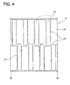
- FIG. 4 shows an inside face of the cap.
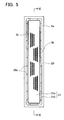
- FIG. 5 shows an enlargement of one capping portion of the cap of FIG. 3 and an ink discharge face of an ink jet head.
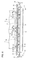
- FIG. 6 shows a cross-sectional view along the line VI-VI of FIG. 5. FIG. 6 also shows a portion of a mechanism for pressing the cap towards the ink discharge face of the ink jet head.
- FIG. 7 shows a front view of essential parts of the embodiment of the ink jet printer in a state where the cap is being moved from the retreated location to a sealing location.
- FIG. 8 shows a front view of a delivery unit in a state where the cap is in the sealing location.
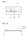
- FIG. 9 shows a process of integrally molding a capping member, a detachment preventing member and a linking member.
- FIG. 10 is a cross sectional view of a cap of a different embodiment.
-
- A preferred embodiment to practice the present invention will now be described. In the present embodiment, the present invention has been applied to a line type color ink jet printer. However, the present invention can also be applied to other types of ink jet printers.
As shown in FIG. 1, an ink jet printer 1 is provided with a total of eight line typeink jet heads 2. Twoink jet heads 2K discharge black ink, twoink jet heads 2M discharge magenta ink, twoink jet heads 2C discharge cyan ink, and twoink jet heads 2Y discharge yellow ink. The ink jet printer 1 is also provided with adelivery unit 3 that delivers paper in the leftwards direction of FIG. 1. The eightink jet heads 2 are aligned in a left-right direction of FIG. 1 (along the direction of delivery of the paper). - An ink
discharging face 2a is formed at a lower face of eachink jet head 2. As shown in FIG. 5, a plurality ofholes 2b is formed in eachink discharge face 2a of eachink jet head 2. Eachhole 2b works as a nozzle for discharging ink. The plurality of thenozzles 2b is divided into four groups, and thenozzles 2b of each group are distributed within a trapezoid area. Four trapezoid areas are arranged in an inner region of theink discharge face 2a, and nonozzles 2b is arranged in an outer boundary region of theink discharge face 2a. A later describedlip member 21b will fits tightly with the outer boundary region having nonozzles 2b for sealingnozzles 2b from the atmosphere.
In FIG. 1, a paper feed tray (not shown) is present at a right side of theink jet heads 2, and a paper discharge tray (not shown) is present at a left side of theink jet heads 2. Thedelivery unit 3 takes paper from the paper feed tray, passes the paper below theink jet heads 2, and sends it to the paper discharge tray. Ink is discharged from theink jet heads 2, and printing of the paper passing below theink jet heads 2 is thus performed.
Both ink jet heads (2K, 2M, 2C, and 2Y) that discharge identically colored ink are adjacent in the direction of delivery of the paper. Eachink jet head 2 extends in a direction orthogonal to the page of FIG. 1, and extends for a length equivalent to approximately half the width of the paper. Both ink jet heads discharging identically colored ink are disposed in locations having displacement therebetween in a direction orthogonal to the page of FIG. 1. As shown in FIG. 3, bothink jet heads 2 discharging identically colored ink are disposed such that end parts thereof overlap when viewed from a direction orthogonal to the paper. Bothink jet heads 2 discharging identically colored ink are used for printing the paper. This allows the entire width of the paper passing below theink jet heads 2 to be printed at the same time. The twoink jet heads 2 discharging identically colored ink have no space therebetween which would cause a blank area in the printing. - As shown in FIG. 1, the
delivery unit 3 is provided with tworollers main body frame 10, acontinuous carrier belt 13 wound across therollers belt receiving unit 14 that engages with thecarrier belt 13 from below. Thebelt receiving unit 14 prevents thecarrier belt 13 from bending downwards between therollers belt receiving unit 14 thus enables thecarrier belt 13 to move horizontally.
Thedelivery unit 3 does not only deliver paper, but is also provided with acap 15 for covering the inkdischarging faces 2a of theink jet heads 2, and with a mechanism for moving thiscap 15. - The
roller 11, which is a driving roller, is linked with a motor (not shown). Driving force of the motor is transmitted to thedriving roller 11, thus rotating and driving thedriving roller 11. Thereupon, thecarrier belt 13 moves between thedriving roller 11 and the roller 12 (a driven roller), and paper mounted on thecarrier belt 13 is delivered from right to left relative to FIG. 1. Moreover, as shown in FIGS. 1 and 2, aguide member 16 is formed at the right side (relative to FIG. 1) of the drivenroller 12. Theguide member 16 is approximately semicircular when viewed frontally. As the drivenroller 12 rotates, theguide member 16 guides movement such that thecarrier belt 13 moves, and the paper is delivered. - As shown in FIGS. 1 and 6, the
belt receiving unit 14 has a base 17 formed in a fixed manner in themain body frame 10, and has abelt receiving member 19 supported by thebase 17 via a plurality of compression springs 18. Thecarrier belt 13 slides along an upper face of thebelt receiving member 19. Thebelt receiving unit 14 supports thecarrier belt 13 from below. Further, as will be described in detail later, when thecap 15 has been mounted below the ink jet heads 2, the energizing force of the compression springs 18 of thebelt receiving unit 14 presses thecap 15 against theink discharging faces 2a of the ink jet heads 2 via thecarrier belt 13. - The
cap 15 fits tightly with theink discharging faces 2a of the ink jet heads 2 to prevent ink in thenozzles 2b of the ink jet heads 2 from drying out, and to recover ink discharged from thenozzles 2b during a purging process. As shown in FIGS. 3 to 6, thecap 15 has asheet member 20 and eight cappingportions 21. The cappingportions 21 are disposed on one face of thesheet member 20 and each of cappingportions 21 can fit tightly with each of theink discharging faces 2a of each of the ink jet heads 2. Further, thecap 15 has adetachment preventing member 23 provided at the other face of thesheet member 20 and linkingmembers 32. The linkingmembers 32 pass through thesheet member 20 and link the cappingportions 21 and thedetachment preventing member 23. - The
sheet member 20 is formed from a flexible material with a low elongation percentage, such as polyimide, polyester, or the like. Thesheet member 20 does not allow the air to pass through. As shown in FIGS. 1, 3, and 4, thesheet member 20 is formed in a sheet shape and, from a plan view, has a rectangular shape. The eight cappingportions 21 formed on one face of thesheet member 20 are disposed in locations corresponding to the eight ink jet heads 2. The capping member of the embodiment includes eight cappingportions 21. - As shown in FIGS. 3 to 6, each capping
portion 21 is provided with abase member 21a and alip member 21b. Eachbase member 21a is formed by a portion of thesheet member 20, and has a plane rectangular shape slightly larger than a plane shape of a region where thenozzles 2b are distributed on theink discharging face 2a. Thelip member 21b surrounds the circumference of thebase member 21a in a frame shape that corresponds to the outer boundary region of theink discharge face 2a. Thelip member 21b rises above thesheet member 20. Thelip members 21b are molded from soft synthetic resin, and adhered to thesheet member 20. Thelip member 21b is softer than thesheet member 20 and easily deformable due its elasticity. Thelip member 21b does not allow the air to pass through. The material of thesheet member 20 is selected to be suitable to thesheet member 20, and the material of thelip member 21b is selected to be suitable to thelip member 21b. The materials of thesheet member 20 and thelip sheet member 21b are different.
When thelip member 21b is pressed against theink discharge face 2a, thelip member 21b deforms resiliently while fitting tightly with the outer region of theink discharging face 2a, thus the cappingportion 21 reliably seals thenozzles 2b distributed on theink discharge face 2a from the atmosphere. - As shown in FIGS. 4 and 6, the
detachment preventing member 23 is provided on the other face of thesheet member 20. Thedetachment preventing member 23 includes eight detachment preventing portions. The shape and location of each of the detachment preventing portions correspond to those of each of the cappingportions 21. The eight detachment preventing portions are mutually connected to form the single commondetachment preventing member 23. That is, a total of eight detachment preventing portions are all linked integrally. - As shown in FIG. 6, the capping
portions 21 formed on one face of thesheet member 20, and thedetachment preventing member 23 formed on the other face of thesheet member 20, are linked by the linkingmembers 32 that pass through thesheet member 20. A plurality ofholes 20a (see FIGS. 5 and 6) is formed in thesheet member 20 in regions that, from a plan view, overlap with thelip members 21b. The linkingmembers 32 pass through theseholes 20a to link the cappingportions 21 and thedetachment preventing member 23. In FIG. 5, theholes 20a should rightfully be shown by a dotted line. However, a solid line has been drawn for the sake of clarity.
Thelip members 21b, thedetachment preventing member 23, and the linkingportions 32 are molded integrally by means of injection molding. As shown in FIG. 9, by injecting soft rubber-like synthetic resin into a cavity of a molding die having anupper die 52 for forming thelip member 21b and lower die 53 for forming thedetachment preventing member 23 in a state that theseat member 20 havingholes 20a is set between theupper die 52 and thelower die 54, thelip members 21b, thedetachment preventing member 23, and the linkingmembers 32 are molded integrally.
Since thelip members 21b are linked with thedetachment preventing member 23 located on the opposite side of thesheet member 20, and thesheet member 20 is held between these two, thelip members 21b do not readily become detached from thesheet member 20.
An inside face of thesheet member 20 slides on theguide member 16 when thecap 15 is moved. At the surface of thesheet member 20 that slides on theguide member 16, thedetachment preventing member 23 for the eight cappingportions 21 is linked integrally, and the face is substantially flat. When thecap 15 is moved between a sealing location (to be described: see FIG. 8) and a retreated location (see FIG. 1), thecap 15 bends during this movement. Simultaneously, as shown in FIG. 2, thedetachment preventing member 23 makes contact with theguide member 16. Since thedetachment preventing member 23 is formed integrally and the surface thereof is substantially flat, thecap 15 can be moved smoothly across theguide member 16. - As shown in FIGS. 3 and 4, a pair of
sheet supporting bars 22 is formed at both end portions of thesheet member 20 in a left-right direction relative to FIG. 3 (the direction of delivery of the paper). Thesheet supporting bars 22 are formed from metal and have a narrow line shape. As shown in FIG. 1, thedelivery unit 3 is provided withbelts 25. Thebelts 25 are formed at a closer side and a further side (relative to the page of FIG. 1) of thepaper carrier belt 13. One end of thesheet supporting bar 22 is linked with thebelt 25 of the closer side via a connectingmember 24 and the other end part of thesheet supporting bar 22 is linked with thebelt 25 of the further side via the connectingmember 24. Thebelts 25 are wound across fourpulleys guide member 16. Thepulleys main body frame 10, and theguide member 16, which is semicircular when viewed frontally, is formed at the right side of drivenroller 12. When thepulley 26 is caused to rotate by a motor (not shown) linked with thispulley 26, thebelts 25 on both sides rotate, and thecap 15 moves therewith. Thecap 15 moves along an outer side of thecarrier belt 13.
Thecap 15 is moved by thebelts 25 between the sealing location (see FIG. 8) and the retreated location (see FIG. 1). In the sealing location, thecap 15 is located between the ink discharge faces 2a of the ink jet heads 2, and thecarrier belt 13. As shown in FIG. 8, thecap 15 is located above thecarrier belt 13. In FIG. 8, the ink jet heads 2 have been omitted and only thedelivery unit 3 is shown so that the location of thecap 15 is shown more clearly. In the sealing location, the capping portions of the cappingmember 21 face theink discharging faces 2a of the ink jet heads 2, and can seal theink jet nozzles 2b distributed on theink discharging faces 2a.
In the retreated location, thecap 15 is located below the carrier belt 13 (see FIG. 1). In the retreated location, thecarrier belt 13 directly faces theink discharging faces 2a of the ink jet heads 2 via the printing paper, so that ink discharged from the ink jet heads 2 is injected onto the printing paper, and printing of the paper passing below the ink jet heads 2 is thus performed. - As shown in FIG. 7, the
main body frame 10 of thedelivery unit 3 can be swung along a vertical plane, with arotational axis 11a of the drivingroller 11 as the center, by means of a swinging device (not shown). Further, themain body frame 10 of thedelivery unit 3 can be raised and lowered relative to the ink jet heads 2 by means of a raising and lowering mechanism (not shown).
In the case where theink discharging faces 2a are to be sealed by thecap 15, themain body frame 10 is first rotated by the swinging device in a clockwise direction relative to FIG. 1, with therotational axis 11a as the center, until thedelivery unit 3 has been swung to the location in FIG. 7. In this state, thepulley 26 is rotated. This moves thecap 15, via thebelts 25, along the outer side of the carrier belt 13 (see FIG. 7) until thecap 15 is located above an upper side of thecarrier belt 13. FIG. 7 shows a state where thecap 15 is being moved from the retreated position to the sealing position. Thecap 15 is bent while moving from the retreated position to the sealing position. When thecap 15 is further moved along the arrow "a", thecap 15 reaches the sealing position as shown in FIG. 8. Then themain body frame 10 is rotated by the swinging device in an counterclockwise direction relative to FIG. 1, with therotational axis 11a as the center, until thedelivery unit 3 has been swung to the location in FIG. 8. In the location shown in FIG. 8, the cappingmembers 21 face the ink jet heads 2. Moreover, themain body frame 10 is moved upwards, relative to the ink jet heads 2, by the raising and lowering mechanism (not shown). As a result, as shown in FIG. 6, the energizing force of the compression springs 18 of thebelt receiving unit 14 presses the cappingmembers 21 of thecap 15, located on the upper side of thecarrier belt 13, against the ink jet heads 2. Theink discharging nozzles 2b at theink discharging faces 2a are thus sealed by the cappingmembers 21. - When the
cap 15 is to be moved between the sealing location (see FIG. 8), in which thecapping members 21 face upwards (facing the ink jet heads 2) and the retreated location (see FIG. 1), in which thecapping members 21 face the opposite side from the ink jet heads 2, thecap 15 slides on the outer circumference part of theguide member 16. At this juncture, the direction of movement of thecap 15 changes from horizontal to vertical, thus necessitating a bending of thecap 15. If thelip members 21b of the cappingmembers 21 were bonded to thesheet member 20 only by means of adhesive or the like, there would be considerable risk of thelip members 21b becoming detached from thesheet member 20 when thecap 15 bends. Further, thelip members 21b would also readily become detached when thelip members 21b are removed from theink discharging faces 2a of the ink jet heads 2.
As shown in FIGS. 4 and 6, in thecap 15 of the present embodiment, the capping members 21 (thelip members 21b) are linked with thedetachment preventing member 23 located on the opposite face of thesheet member 20 relative to the cappingmembers 21, and thesheet member 20 is held between these two parts. This prevents the cappingmembers 21 from becoming detached from thesheet member 20.
There may be no risk of thelip members 21b being detached from thesheet member 20, if thelip members 21b and thesheet member 20 are integrally formed. However, thesheet member 20 must be formed from a material having a low elongation percentage. If thesheet member 20 is elongated, thesheet member 20 can not be moved by the rotation of thepulley 26. On the contrary, thelip members 21b must be formed from a soft rubber-like material. In the embodiment, thesheet member 20 made from the suitable material for thesheet member 20 and thelip member 21b made from the suitable material for thelip member 21b, the materials being different, can be held tightly. - Next, variations on the above embodiment will be described. Components configured identically to those of the above embodiment have the same reference numbers assigned thereto and a description thereof is omitted.
The shape of the capping member or the detachment preventing member is not limited to the shape in the above embodiment. For example, as shown in FIG. 10, a cappingmember 31 may have abase member 31a that overlaps with thesheet member 20, and alip member 31b that surrounds a circumference of thebase member 31a, with thebase member 31a and thelip member 31b being molded integrally from soft synthetic resin. If the cappingmember 31 has this structure, the cappingmember 31 fits more tightly to theink discharging face 2a. Thelip member 31b and thedetachment preventing member 23 may be molded integrally, as is the case in the above embodiment. However, thebase member 31a and thedetachment preventing member 23 may equally well be molded integrally. In this case, also, the cappingmember 31 at the surface face side and thedetachment preventing member 23 at the inside face side are linked by the linkingmember 32 that passes through thesheet member 20. The detachment of the cappingmember 31 is thus prevented. - The detachment preventing member may project beyond an area corresponding to the inside side of the
lip members sheet member 20. In this case, an inside face side of the cap is also flat, and the cap can consequently move more smoothly. - The moving means of the cap is not limited to the
belts 25 of the embodiment. For example, the cap may be moved between the sealing location and the retreated location via a line-shaped member, such as a wire or the like, wound across a plurality of pulleys. Moreover, a configuration is also possible in which the sealing location and the retreated location are located within an identical horizontal plane, and the cap can be moved within this plane between the sealing location and the retreated location. - According to an exemplary embodiment, it is preferred that the capping member, the linking member, and the detachment preventing member are molded integrally. The capping member, the linking member, and the detachment preventing member can be molded integrally by setting the sheet member, which has holes dispersed in a region of forming the capping member, in an injection molding die and performing injection molding thereof. This integral molding prevents the capping member from readily becoming detached from the sheet member.
- According to an exemplary embodiment, a plurality of ink jet heads may be mounted in an ink jet printer. In this case, the capping member may be provided with a plurality of capping portions that is disposed on one face of a single sheet member. Each capping portion fits tightly with each ink discharging face of each ink jet head. The detachment preventing member may be provided with a plurality of detachment preventing portions that is disposed on the other face of the single sheet member. Each detachment preventing portion corresponds to each capping portion. In this case, it is preferred that the detachment preventing portions that correspond to the capping portions are formed continuously, such that a single common detachment preventing member is formed.
According to an exemplary embodiment, in this case, each capping portion is linked with the large common detachment preventing member, and the capping portions consequently become detached from the sheet member even less readily. Further, a surface of the detachment preventing member can consequently be almost flat. As a result, each capping portion can easily be fitted tightly with the corresponding ink discharging face. - According to an exemplary embodiment, the cap is particularly useful when the cap is integrated with a mechanism that moves the cap, utilizing a belt or a wire wound across a plurality of pulleys, between a location where the cap fits tightly with the ink discharging face and a location where the cap is distant from the ink discharging face.
According to an exemplary embodiment, in the case where the cap is moved utilizing a belt or a wire wound across a plurality of pulleys, the capping member or capping portions tend to readily become detached from the sheet member when the pulleys cause the cap to bend. In the cap of an exemplary embodiment of the present invention, however, the detachment preventing member or detachment preventing portions support the capping member or capping portions from the face at the opposite side of the sheet member, with the sheet member being held between the capping member and the detachment preventing member. This reliably prevents the capping member or capping portions from becoming detached from the sheet member.
According to an exemplary embodiment, in the case where the cap is moved utilizing a belt or a wire wound across a plurality of pulleys, it is particularly preferred that the detachment preventing portions are mutually connected, such that a single common detachment preventing member is formed. A surface of the detachment preventing member can consequently be almost flat, and consequently it is easy to move the cap smoothly around pulleys.
Claims (7)
- A cap for sealing nozzles of an ink jet head for discharging ink, comprising:characterized in that the cap further comprising:a sheet member; anda capping member formed on one face of the sheet member, the capping member being capable of fitting tightly with an ink discharging face on which the nozzles are formed,a detachment preventing member formed on the other face of the sheet member; anda linking member passing through the sheet member and linking the capping member and the detachment preventing member.
- A cap of claim 1,
wherein the capping member includes a plurality of capping portions that is provided on one face of the sheet member, and the detachment preventing member includes a plurality of detachment preventing portions that is provided on the other face of the sheet member, and
wherein a plurality of the detachment preventing portions, each detachment preventing portion corresponding to each capping portion, are mutually connected. - A cap of claim 1,
wherein the capping member includes a plurality of capping portions that is provided on one face of the sheet member,
wherein a single common detachment preventing member is formed on the other face of the sheet member, and
wherein the plurality of capping portions is linked with the single common detachment preventing member. - A cap of any one of claims 1 to 3,
wherein the capping member, the detachment preventing member, and the linking member are molded integrally. - A cap of any one of claims 1 to 4,
wherein the cap is linked with a belt or a wire wound across a plurality of pulleys, and
wherein the cap is moved by means of the belt or the wire between a sealing location wherein the cap fits tightly with the ink discharging face and a retreated location wherein the cap is distant from the ink discharging face. - An ink jet head assembly including:an ink jet head; anda cap according to any preceding claim.
- A printer including an ink jet printer according to claim 6.
Applications Claiming Priority (2)
| Application Number | Priority Date | Filing Date | Title |
|---|---|---|---|
| JP2004084488 | 2004-03-23 | ||
| JP2004084488 | 2004-03-23 |
Publications (3)
| Publication Number | Publication Date |
|---|---|
| EP1582356A2 true EP1582356A2 (en) | 2005-10-05 |
| EP1582356A3 EP1582356A3 (en) | 2006-01-18 |
| EP1582356B1 EP1582356B1 (en) | 2013-06-05 |
Family
ID=34879875
Family Applications (1)
| Application Number | Title | Priority Date | Filing Date |
|---|---|---|---|
| EP05251725.7A Ceased EP1582356B1 (en) | 2004-03-23 | 2005-03-22 | Cap for ink jet head |
Country Status (4)
| Country | Link |
|---|---|
| US (1) | US20050219308A1 (en) |
| EP (1) | EP1582356B1 (en) |
| JP (1) | JP5099104B2 (en) |
| CN (1) | CN100366431C (en) |
Cited By (2)
| Publication number | Priority date | Publication date | Assignee | Title |
|---|---|---|---|---|
| WO2006060843A1 (en) | 2004-12-06 | 2006-06-15 | Silverbrook Research Pty Ltd | Capping system incorporating a flexible capping member for inkjet printhead assembly |
| US7758148B2 (en) | 2004-12-06 | 2010-07-20 | Silverbrook Research Pty Ltd | Capping system incorporating a flexible capping member for inkjet printhead assembly |
Families Citing this family (7)
| Publication number | Priority date | Publication date | Assignee | Title |
|---|---|---|---|---|
| US7445311B2 (en) * | 2005-12-05 | 2008-11-04 | Silverbrook Research Pty Ltd | Printhead maintenance station having maintenance belt |
| US7448724B2 (en) * | 2005-12-05 | 2008-11-11 | Silverbrook Research Pty Ltd | Method of maintaining a printhead using a maintenance belt |
| US7452052B2 (en) * | 2005-12-05 | 2008-11-18 | Silverbrook Research Pty Ltd | Printhead maintenance assembly having maintenance belt |
| US7455383B2 (en) * | 2005-12-05 | 2008-11-25 | Silverbrook Research Pty Ltd | Printhead maintenance station having maintenance belt with belt-cleaning station |
| US7871149B2 (en) * | 2007-03-12 | 2011-01-18 | Brother Kogyo Kabushiki Kaisha | Head unit and ink-jet recording apparatus having the same |
| JP5429048B2 (en) * | 2010-05-25 | 2014-02-26 | セイコーエプソン株式会社 | Maintenance device, fluid ejection device, and maintenance method |
| JP6409428B2 (en) | 2014-09-08 | 2018-10-24 | セイコーエプソン株式会社 | Liquid ejector |
Citations (2)
| Publication number | Priority date | Publication date | Assignee | Title |
|---|---|---|---|---|
| JP2001253080A (en) | 2000-03-13 | 2001-09-18 | Sony Corp | Printer device performance maintenance sheet |
| US20030081049A1 (en) | 2001-10-31 | 2003-05-01 | Davis Jeremy A. | Positive stop capping system for inkjet printheads |
Family Cites Families (15)
| Publication number | Priority date | Publication date | Assignee | Title |
|---|---|---|---|---|
| US4369456A (en) * | 1981-08-26 | 1983-01-18 | Pitney Bowes Inc. | Cleaning device for writing heads used in ink jet recorders and printers |
| JPH09123470A (en) * | 1995-08-30 | 1997-05-13 | Mita Ind Co Ltd | Ink jet recorder |
| JPH09164693A (en) * | 1995-11-27 | 1997-06-24 | Xerox Corp | Liquid ink printer equipped with consumable goods for maintenance |
| US5956053A (en) * | 1996-10-31 | 1999-09-21 | Hewlett-Packard Company | Dual seal capping system for inkjet printheads |
| US5936647A (en) * | 1996-10-31 | 1999-08-10 | Hewlett-Packard Company | Flexible frame onsert capping of inkjet printheads |
| JP4022946B2 (en) * | 1996-11-15 | 2007-12-19 | ブラザー工業株式会社 | Capping device |
| JPH10322046A (en) * | 1997-05-22 | 1998-12-04 | Tokai Rubber Ind Ltd | Seal structure |
| JP3728963B2 (en) * | 1999-01-25 | 2005-12-21 | セイコーエプソン株式会社 | Inkjet recording device |
| US6406124B1 (en) * | 2000-01-31 | 2002-06-18 | Hewlett-Packard Company | Ganged inkjet printhead capping system |
| US6585347B1 (en) * | 2000-01-31 | 2003-07-01 | Hewlett-Packard Company | Printhead servicing based on relocating stationary print cartridges away from print zone |
| JP4790107B2 (en) * | 2000-10-13 | 2011-10-12 | オリンパス株式会社 | Printer |
| JP2002156044A (en) * | 2000-11-21 | 2002-05-31 | Nok Corp | Gasket |
| US6540323B1 (en) * | 2002-01-31 | 2003-04-01 | Hewlett-Packard Development Company, L.P. | Snout-encompassing capping system for inkjet printheads |
| JP3879717B2 (en) * | 2003-08-05 | 2007-02-14 | ブラザー工業株式会社 | Inkjet printer |
| JP2005193568A (en) * | 2004-01-08 | 2005-07-21 | Sony Corp | Nozzle cap, head cap unit, and liquid discharge head |
-
2005
- 2005-03-22 EP EP05251725.7A patent/EP1582356B1/en not_active Ceased
- 2005-03-23 CN CNB2005100592151A patent/CN100366431C/en not_active Expired - Fee Related
- 2005-03-23 US US11/086,753 patent/US20050219308A1/en not_active Abandoned
-
2009
- 2009-11-02 JP JP2009251735A patent/JP5099104B2/en not_active Expired - Fee Related
Patent Citations (2)
| Publication number | Priority date | Publication date | Assignee | Title |
|---|---|---|---|---|
| JP2001253080A (en) | 2000-03-13 | 2001-09-18 | Sony Corp | Printer device performance maintenance sheet |
| US20030081049A1 (en) | 2001-10-31 | 2003-05-01 | Davis Jeremy A. | Positive stop capping system for inkjet printheads |
Cited By (3)
| Publication number | Priority date | Publication date | Assignee | Title |
|---|---|---|---|---|
| WO2006060843A1 (en) | 2004-12-06 | 2006-06-15 | Silverbrook Research Pty Ltd | Capping system incorporating a flexible capping member for inkjet printhead assembly |
| EP1827837A4 (en) * | 2004-12-06 | 2008-05-07 | Silverbrook Res Pty Ltd | Capping system incorporating a flexible capping member for inkjet printhead assembly |
| US7758148B2 (en) | 2004-12-06 | 2010-07-20 | Silverbrook Research Pty Ltd | Capping system incorporating a flexible capping member for inkjet printhead assembly |
Also Published As
| Publication number | Publication date |
|---|---|
| JP5099104B2 (en) | 2012-12-12 |
| CN1672941A (en) | 2005-09-28 |
| JP2010023523A (en) | 2010-02-04 |
| US20050219308A1 (en) | 2005-10-06 |
| CN100366431C (en) | 2008-02-06 |
| EP1582356A3 (en) | 2006-01-18 |
| EP1582356B1 (en) | 2013-06-05 |
Similar Documents
| Publication | Publication Date | Title |
|---|---|---|
| JP4998243B2 (en) | Liquid ejection device | |
| JP5099104B2 (en) | Ink-jet head cap and cap device | |
| US7114793B2 (en) | Recording apparatus | |
| JP5100491B2 (en) | Printer device | |
| US8297733B2 (en) | Ink jet recording apparatus having recovery device | |
| US10322585B2 (en) | Inkjet printer | |
| KR102768174B1 (en) | Carriage apparatus and printing apparatus | |
| US20050041059A1 (en) | Inkjet printer | |
| KR102098673B1 (en) | Printing apparatus | |
| US6443552B1 (en) | Carriage moving apparatus, recording apparatus and reading apparatus | |
| CN100475539C (en) | Ink-jet image forming apparatus having cap member | |
| US8333466B2 (en) | Ink jet recording apparatus | |
| JP2002234151A (en) | Recording head unit and ink jet recording apparatus | |
| JP4428258B2 (en) | Inkjet head cap | |
| US7011387B2 (en) | Tube pump, discharge recovering apparatus and ink jet recording apparatus | |
| US8191990B2 (en) | Inkjet recording apparatus | |
| US10399341B2 (en) | Inkjet printer | |
| EP1974923A1 (en) | Inkjet recording device | |
| EP1607223A1 (en) | Ink jet printer | |
| JP4693166B2 (en) | Inkjet recording device | |
| US20220402271A1 (en) | Cap and inkjet printer including the same | |
| JP2004092602A (en) | Tube pump and inkjet recording device | |
| JP7043385B2 (en) | Inkjet printer and computer program for cleaning | |
| JP4978613B2 (en) | Head cap | |
| JP2019051599A (en) | Inkjet printer |
Legal Events
| Date | Code | Title | Description |
|---|---|---|---|
| PUAI | Public reference made under article 153(3) epc to a published international application that has entered the european phase |
Free format text: ORIGINAL CODE: 0009012 |
|
| AK | Designated contracting states |
Kind code of ref document: A2 Designated state(s): AT BE BG CH CY CZ DE DK EE ES FI FR GB GR HU IE IS IT LI LT LU MC NL PL PT RO SE SI SK TR |
|
| AX | Request for extension of the european patent |
Extension state: AL BA HR LV MK YU |
|
| PUAL | Search report despatched |
Free format text: ORIGINAL CODE: 0009013 |
|
| AK | Designated contracting states |
Kind code of ref document: A3 Designated state(s): AT BE BG CH CY CZ DE DK EE ES FI FR GB GR HU IE IS IT LI LT LU MC NL PL PT RO SE SI SK TR |
|
| AX | Request for extension of the european patent |
Extension state: AL BA HR LV MK YU |
|
| 17P | Request for examination filed |
Effective date: 20060504 |
|
| AKX | Designation fees paid |
Designated state(s): DE FR GB |
|
| 17Q | First examination report despatched |
Effective date: 20081107 |
|
| GRAP | Despatch of communication of intention to grant a patent |
Free format text: ORIGINAL CODE: EPIDOSNIGR1 |
|
| GRAS | Grant fee paid |
Free format text: ORIGINAL CODE: EPIDOSNIGR3 |
|
| GRAA | (expected) grant |
Free format text: ORIGINAL CODE: 0009210 |
|
| AK | Designated contracting states |
Kind code of ref document: B1 Designated state(s): DE FR GB |
|
| REG | Reference to a national code |
Ref country code: GB Ref legal event code: FG4D |
|
| REG | Reference to a national code |
Ref country code: DE Ref legal event code: R096 Ref document number: 602005039872 Country of ref document: DE Effective date: 20130801 |
|
| PLBE | No opposition filed within time limit |
Free format text: ORIGINAL CODE: 0009261 |
|
| STAA | Information on the status of an ep patent application or granted ep patent |
Free format text: STATUS: NO OPPOSITION FILED WITHIN TIME LIMIT |
|
| 26N | No opposition filed |
Effective date: 20140306 |
|
| REG | Reference to a national code |
Ref country code: DE Ref legal event code: R097 Ref document number: 602005039872 Country of ref document: DE Effective date: 20140306 |
|
| REG | Reference to a national code |
Ref country code: FR Ref legal event code: PLFP Year of fee payment: 12 |
|
| REG | Reference to a national code |
Ref country code: FR Ref legal event code: PLFP Year of fee payment: 13 |
|
| REG | Reference to a national code |
Ref country code: FR Ref legal event code: PLFP Year of fee payment: 14 |
|
| PGFP | Annual fee paid to national office [announced via postgrant information from national office to epo] |
Ref country code: GB Payment date: 20190227 Year of fee payment: 15 Ref country code: DE Payment date: 20190215 Year of fee payment: 15 |
|
| PGFP | Annual fee paid to national office [announced via postgrant information from national office to epo] |
Ref country code: FR Payment date: 20190220 Year of fee payment: 15 |
|
| REG | Reference to a national code |
Ref country code: DE Ref legal event code: R119 Ref document number: 602005039872 Country of ref document: DE |
|
| PG25 | Lapsed in a contracting state [announced via postgrant information from national office to epo] |
Ref country code: FR Free format text: LAPSE BECAUSE OF NON-PAYMENT OF DUE FEES Effective date: 20200331 Ref country code: DE Free format text: LAPSE BECAUSE OF NON-PAYMENT OF DUE FEES Effective date: 20201001 |
|
| GBPC | Gb: european patent ceased through non-payment of renewal fee |
Effective date: 20200322 |
|
| PG25 | Lapsed in a contracting state [announced via postgrant information from national office to epo] |
Ref country code: GB Free format text: LAPSE BECAUSE OF NON-PAYMENT OF DUE FEES Effective date: 20200322 |