EP1582313A2 - Power tool - Google Patents
Power tool Download PDFInfo
- Publication number
- EP1582313A2 EP1582313A2 EP05251668A EP05251668A EP1582313A2 EP 1582313 A2 EP1582313 A2 EP 1582313A2 EP 05251668 A EP05251668 A EP 05251668A EP 05251668 A EP05251668 A EP 05251668A EP 1582313 A2 EP1582313 A2 EP 1582313A2
- Authority
- EP
- European Patent Office
- Prior art keywords
- handle
- housing
- power tool
- supporting wall
- elongate supporting
- Prior art date
- Legal status (The legal status is an assumption and is not a legal conclusion. Google has not performed a legal analysis and makes no representation as to the accuracy of the status listed.)
- Granted
Links
Images


Classifications
-
- B—PERFORMING OPERATIONS; TRANSPORTING
- B25—HAND TOOLS; PORTABLE POWER-DRIVEN TOOLS; MANIPULATORS
- B25F—COMBINATION OR MULTI-PURPOSE TOOLS NOT OTHERWISE PROVIDED FOR; DETAILS OR COMPONENTS OF PORTABLE POWER-DRIVEN TOOLS NOT PARTICULARLY RELATED TO THE OPERATIONS PERFORMED AND NOT OTHERWISE PROVIDED FOR
- B25F5/00—Details or components of portable power-driven tools not particularly related to the operations performed and not otherwise provided for
- B25F5/02—Construction of casings, bodies or handles
Definitions
- the present invention relates to a power tool with an adjustable handle.
- EP-A-1203628 and US-A-5533581 disclose adjustable handles for power tools (in particular for a reciprocating saw and a drill).
- the housing of such power tools is generally elongated and the adjustable handle is pivotally attached to a rear end of the housing.
- One drawback of such a construction is that the adjustable handle is not securely and reliably supported and may therefore be dangerous.
- Another drawback is that the structure of the power tool as a whole is inconveniently bulky.
- the present invention seeks to improve power tools by providing a rigid and compact structure for securely supporting an adjustable handle.
- a power tool comprising:
- the housing is multiply walled.
- the elongate supporting wall may extend slantwise and downwardly from the remaining walls of the housing.
- the elongate supporting wall is an elongate abutment wall.
- an angle ⁇ is formed between an axis of the motor and an axis of the output shaft, wherein ⁇ is greater than zero but less than 180 degrees. Particularly preferably ⁇ is about 90 degrees.
- the elongate supporting wall is substantially U-shaped.
- the elongate supporting wall substantially encapsulates a part of the handle.
- the elongate supporting wall comprises:
- the guiding structure and guided structure are of a complementary male and female configuration.
- the guiding structure slidably engages the guided structure in a lateral direction (eg perpendicular to the axis of the elongate supporting wall).
- the guiding structure is a pair of arc-shaped guiding bars and the guided structure is a pair of arc-shaped slots to slidably receive the guiding bars.
- the pair of guiding bars extend laterally in opposite directions (eg perpendicular to the axis of the elongate supporting wall).
- the pair of guiding bars extend laterally inwardly.
- the elongate supporting wall comprises:
- the handle is interlocked with the housing.
- the abutment surface may extend between the pair of guiding bars.
- the abutment surface is stepped.
- the abutment surface comprises: a pair of raised shoulders selectively abuttable against an outer circumferential surface of the handle.
- the handle is interlocked with the housing.
- the pair of raised shoulders may be substantially perpendicular to the plane of the housing.
- the pair of raised shoulders may be substantially perpendicular to the plane of the handle.
- the handle is substantially D-shaped.
- the handle has a distal gripping portion contiguous with a proximal non-gripping portion supported on the elongate supporting wall of the housing, wherein an outer circumferential surface of the proximal non-gripping portion is provided with an elongate engaging portion arcuately engageable with the elongate supporting wall so that the handle can slide along the elongate supporting wall to allow the orientation of the handle and the housing to be angularly adjustable.
- the handle is substantially D-shaped and the elongate supporting wall is arc-shaped, wherein the outer circumferential surface of the proximal non-gripping portion is arc-shaped to generally match the elongate supporting wall.
- the power tool further comprises:
- the power tool is an electrical drill or a reciprocating saw.
- the elongate supporting wall comprises;
- the first distortable structure and/or the second distortable structure may be an apertured flange (preferably a twin apertured flange).
- the or each aperture on respective flanges is coincident to receive a lateral connecting pin or fastener.
- An actuating member adjacent to the surface of the first distortable structure may be actuatable to cause the outer circumferential surface of the handle to be abutted against the elongate supporting wall to interlock the handle with the housing.
- each end of the actuating member may comprise an eccentric cam which when the actuating member is actuated causes the first distortable structure to inwardly displace ( eg rotate inwardly and distort) to cause the outer circumferential surface of the handle to be abutted against the elongate supporting wall to interlock the handle with the housing.
- a clearance is claimed between the first distortable structure and the second distortable structure when the actuating member is not actuated.
- the elongate supporting wall is in the common plane of the housing and handle.
- a power tool comprising:
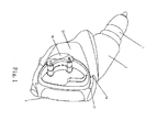
- a power drill includes generally a housing 2 for the main mechanical and electrical components of the drill, a working piece 1 mounted on a distal end of the housing 2 and an adjustable handle 3 supported on an elongate supporting wall 12 of the housing 2.
- the elongate supporting wal112 extends rearwards and slantwise from the remainder of the housing 2.
- a transmission device 4 couples a rotary motor 7 and an output shaft 5 which directly drives the working piece 1 and includes a pair of bevel gears 6.
- An angle ⁇ of about 90 degrees is formed between an axis X1 of the motor 7 and an axis X2 of the output shaft 5.
- the housing 2 is effectively a T shape.
- the part of the housing 2 bearing the elongate supporting wall 12 is a motor-containing part which is contiguous with (and substantially perpendicular to) a transmission device-containing part.
- the handle 3 is substantially D-shaped with a distal gripping portion 32 contiguous with a proximal non-gripping portion 34.
- a locking assembly 16 interlocks the housing 2 to the handle 3 when the desired relative orientation of the distal gripping portion and the housing 2 is achieved.
- Preferred locking assemblies 16 are described in detail in a copending European patent application filed by the applicant on an even date herewith bearing the title "A Power Tool”.
- each side face of the proximal non-gripping portion 34 is provided with an arc-shaped bar 14 claimed inwardly and along the elongate supporting wall 12.
- the proximal non-gripping portion 34 can slide along the arc-shaped bar 14 so that the handle 3 is adjustably mounted on the elongate supporting wall 12.
- the elongate supporting wall 12 comprises a support surface 18 and a pair of raised shoulders 19 formed between the arc-shaped bars 14 to abut against an outer circumferential surface 22 of the proximal non-gripping portion 34 of the handle 3 when the handle 3 is interlocked with the housing 2.
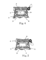
- the configuration of the locking assembly 16 in an unlocked state is shown in Figure 4.
- a small void is formed between the outer circumferential surface 22 of the handle 3 and the support surface 18 and raised shoulders 19.
- the configuration of the locking assembly 16 in a locked state is shown in Figure 5.
- the outer circumferential surface 22 of the proximal non-gripping portion 34 abuts against the abutting surface 18 and the pair of shoulder 19 whereby the handle 3 is securely and reliably interlocked with the housing 2 and supported by the elongate supporting wall 12.
Landscapes
- Engineering & Computer Science (AREA)
- Mechanical Engineering (AREA)
- Drilling And Boring (AREA)
- Sawing (AREA)
Abstract
Description
- a guided structure, wherein the guided structure is slidably engaged with the guiding structure.
Claims (13)
- A power tool comprising:wherein an elongate supporting wall (12) at the first end of the housing (2) is adapted to support the handle (3) substantially in a common plane with the housing (2) in a manner such that the handle (3) is selectively angularly adjustable relative to the housing (2) or interlocked with the housing (2).an electric motor (7);a working piece (1) for mounting a cutting element;a housing (2) for housing the electric motor (7) towards a first end, wherein the housing (2) is adapted to externally mount the working piece (1) at a second end;an output shaft (5) driven by the electric motor (7) for driving the working piece (1);a handle (3),
- The power tool as claimed in claim 1 wherein an angle α is formed between an axis (X1) of the motor (7) and an axis (X2) of the output shaft (5), wherein α is greater than zero but less than 180 degrees.
- The power tool as claimed in claim 2 wherein α is about 90 degrees.
- The power tool as claimed in any preceding claim wherein the elongate supporting wall encapsulates a part of the handle (3).
- The power tool as claimed in claim 1 wherein the elongate supporting wall (12) comprises:and the handle (3) comprises:a guiding structure (14)wherein the guided structure (21) is slidably engaged with the guiding structure (14).a guided structure (21),
- The power tool as claimed in claim 5 wherein the guiding structure (14) is a pair of arc-shaped guiding bars (14) and the guided structure (21) is a pair of arc-shaped slots to slidably receive the guiding bars (14)
- The power tool as claimed in any preceding claim wherein the elongate supporting wall (12) comprises:an abutment surface (18) selectively abuttable against an outer circumferential surface (22) of the handle (3).
- The power tool as claimed in claim 7 wherein when the abutment surface (18) is abutted against the outer circumferential surface (22) of the handle (3), the handle (3) is interlocked with the housing (2).
- The power tool as claimed in claim 7 or 8 wherein the abutment surface is stepped.
- The power tool as claimed in any of claims 7 to 9 wherein the abutment surface (18) extends between the pair of guiding bars (14) and comprises:a pair of raised shoulders (19) selectively abuttable against an outer circumferential surface (22) of the handle (3).
- The power tool as claimed in claim 9 or 10 wherein when the pair of raised shoulders (19) is abutted against the outer circumferential surface (22) of the handle (3), the handle (3) is interlocked with the housing (2).
- The power tool as claimed in any preceding claim wherein the handle is substantially D-shaped.
- The power tool as claimed in any preceding claim being an electrical drill or a reciprocating saw.
Priority Applications (1)
| Application Number | Priority Date | Filing Date | Title |
|---|---|---|---|
| EP05010709A EP1602455B1 (en) | 2004-03-18 | 2005-03-18 | Power tool |
Applications Claiming Priority (6)
| Application Number | Priority Date | Filing Date | Title |
|---|---|---|---|
| CN200410014373 | 2004-03-18 | ||
| CN200410014373 | 2004-03-18 | ||
| CN200410014439 | 2004-03-22 | ||
| CN200410014439 | 2004-03-22 | ||
| CN200420025925U | 2004-03-30 | ||
| CN 200420025925 CN2691797Y (en) | 2004-03-30 | 2004-03-30 | Electric tool |
Related Child Applications (1)
| Application Number | Title | Priority Date | Filing Date |
|---|---|---|---|
| EP05010709A Division EP1602455B1 (en) | 2004-03-18 | 2005-03-18 | Power tool |
Publications (3)
| Publication Number | Publication Date |
|---|---|
| EP1582313A2 true EP1582313A2 (en) | 2005-10-05 |
| EP1582313A3 EP1582313A3 (en) | 2005-10-12 |
| EP1582313B1 EP1582313B1 (en) | 2008-05-14 |
Family
ID=34890691
Family Applications (2)
| Application Number | Title | Priority Date | Filing Date |
|---|---|---|---|
| EP05251668A Expired - Lifetime EP1582313B1 (en) | 2004-03-18 | 2005-03-18 | Power tool |
| EP05010709A Expired - Lifetime EP1602455B1 (en) | 2004-03-18 | 2005-03-18 | Power tool |
Family Applications After (1)
| Application Number | Title | Priority Date | Filing Date |
|---|---|---|---|
| EP05010709A Expired - Lifetime EP1602455B1 (en) | 2004-03-18 | 2005-03-18 | Power tool |
Country Status (3)
| Country | Link |
|---|---|
| US (2) | US7318486B2 (en) |
| EP (2) | EP1582313B1 (en) |
| DE (2) | DE602005006342T2 (en) |
Cited By (1)
| Publication number | Priority date | Publication date | Assignee | Title |
|---|---|---|---|---|
| GB2489864A (en) * | 2008-03-07 | 2012-10-10 | Milwaukee Electric Tool Corp | Ergonomic Reciprocating Saw |
Families Citing this family (16)
| Publication number | Priority date | Publication date | Assignee | Title |
|---|---|---|---|---|
| US20090065228A1 (en) * | 2005-12-09 | 2009-03-12 | Koichi Hashimoto | Power impact tool |
| KR100778125B1 (en) * | 2005-12-19 | 2007-11-21 | 삼성광주전자 주식회사 | Compact Robot Cleaner |
| ES2524560T3 (en) * | 2008-05-14 | 2014-12-10 | Robatech Ag | Manual applicator |
| US20150113814A2 (en) * | 2010-08-18 | 2015-04-30 | Jacob Cuzdey | Convertible zero-clearance circular saw |
| USD674263S1 (en) | 2010-10-15 | 2013-01-15 | Robert Bosch Gmbh | Saw |
| US9038745B2 (en) | 2010-12-20 | 2015-05-26 | Brigham Young University | Hand power tool and drive train |
| US9630310B2 (en) | 2013-02-01 | 2017-04-25 | Makita Corporation | Electric tool |
| DE102013210391A1 (en) * | 2013-06-05 | 2014-12-11 | Robert Bosch Gmbh | power tool |
| USD802392S1 (en) | 2016-05-23 | 2017-11-14 | Cuz-D Manufacturing, Inc. | Circular saw blade |
| USD802393S1 (en) | 2016-05-23 | 2017-11-14 | Cuz-D Manufacturing, Inc. | Circular saw blade |
| USD819419S1 (en) | 2016-05-23 | 2018-06-05 | Cuz-D Manufacturing, Inc. | Circular saw blade |
| USD802391S1 (en) | 2016-05-23 | 2017-11-14 | Cuz-D Manufacturing, Inc. | Arbor for a circular saw |
| USD889241S1 (en) * | 2018-10-11 | 2020-07-07 | David Kresge | Power tool handle portion |
| US11498198B2 (en) * | 2019-08-20 | 2022-11-15 | The Boeing Company | Ergonomic handle for a power tool |
| US12347886B2 (en) * | 2023-01-08 | 2025-07-01 | Michael H Panosian | One-handed power-tool accepting different kinds of batteries |
| US12341212B2 (en) * | 2023-01-08 | 2025-06-24 | Michael H Panosian | One-handed power-tool battery ejection apparatus |
Family Cites Families (31)
| Publication number | Priority date | Publication date | Assignee | Title |
|---|---|---|---|---|
| US2588477A (en) * | 1947-11-13 | 1952-03-11 | Martin L Briggs | Power tool |
| US3785053A (en) * | 1972-07-07 | 1974-01-15 | Pan Technic Inc | Combination saw |
| US4347450A (en) * | 1980-12-10 | 1982-08-31 | Colligan Wallace M | Portable power tool |
| US4543264A (en) * | 1982-08-23 | 1985-09-24 | Land O'lakes, Inc. | Method of treating oilseed material |
| SE446698B (en) | 1983-09-16 | 1986-10-06 | Atlas Copco Ab | "HANDLING MACHINE TOOLS INCLUDING A MOTOR HOUSE AND TWO HOUSE FITTED HANDLES OF ANY ATMINSTONE THAT ARE ADJUSTABLE TO YOU" |
| US4643264A (en) * | 1984-11-06 | 1987-02-17 | Mobil Oil Corporation | Method for reducing drilling torque in the drilling of a deviated wellbore |
| DE4022668A1 (en) * | 1990-07-17 | 1992-01-23 | Bosch Gmbh Robert | ELECTRIC HAND TOOL, IN PARTICULAR ANGLE GRINDING MACHINE |
| US5161293A (en) * | 1991-04-15 | 1992-11-10 | Ebbert Engineering, Inc. | Adjustable handle for hand tool |
| DE4116343A1 (en) * | 1991-05-18 | 1992-11-19 | Bosch Gmbh Robert | HAND-MADE ELECTRIC TOOL, ESPECIALLY DRILLING MACHINE |
| US5134777A (en) * | 1991-12-05 | 1992-08-04 | Skil Corporation | Adjustable stroke reciprocating mechanism for a power tool |
| US5737982A (en) | 1996-10-07 | 1998-04-14 | Lin; Jack | Ratchet tool control mechanism |
| US6000302A (en) | 1998-04-07 | 1999-12-14 | Chiang; Der Ching | Tool having rotatable driving head |
| US6108916A (en) | 1998-08-14 | 2000-08-29 | Milwaukee Electric Tool Corporation | Movable handle for a power tool |
| EP1016505B1 (en) * | 1998-12-31 | 2005-01-19 | C. & E. Fein GmbH | Electric power tool, especially an angle grinder |
| US6439088B1 (en) * | 2000-04-25 | 2002-08-27 | The Toro Company | Reconfigurable vegetation trimmer and method of use |
| DE20013486U1 (en) | 2000-08-04 | 2000-10-19 | Lin, Fu-Hui, Taichung | Angle adjustable screwdriver arrangement |
| EP1203628A3 (en) | 2000-11-02 | 2003-02-12 | Milwaukee Electric Tool Corporation | Handle arrangement for a reciprocating saw |
| US6386075B1 (en) | 2001-05-03 | 2002-05-14 | Hsuan-Sen Shiao | Swingable handle adapted for rotating a tool bit of a hand tool |
| DE10134000B4 (en) * | 2001-07-12 | 2004-09-02 | Gabor Paulke | Drilling machine for mains and battery operation |
| US6364033B1 (en) | 2001-08-27 | 2002-04-02 | Techtronic Industries Co. Ltd. | Portable electric tool |
| US6742266B2 (en) * | 2001-10-04 | 2004-06-01 | Robson L. Splane, Jr. | Miniature reciprocating saw device |
| GB2382044A (en) | 2001-11-20 | 2003-05-21 | Black & Decker Inc | A power tool having a handle and a pivotal tool body |
| US6912790B2 (en) * | 2001-12-03 | 2005-07-05 | Milwaukee Electric Tool Corporation | Handle arrangement for a reciprocating saw |
| JP3706335B2 (en) * | 2001-12-12 | 2005-10-12 | 本田技研工業株式会社 | Internal combustion engine failure determination device |
| US6671969B2 (en) | 2001-12-18 | 2004-01-06 | Porter-Cable/Delta | Adjustable shoe for a reciprocating saw |
| US20030200841A1 (en) | 2002-04-24 | 2003-10-30 | S-B Power Tool Corporation | Articulation lock and pivotable tool using same |
| DE60320484T2 (en) | 2002-06-07 | 2009-05-14 | Black & Decker Inc., Newark | Powered tool with blocking device |
| JP4270887B2 (en) * | 2003-01-10 | 2009-06-03 | 株式会社マキタ | Electric reciprocating tool |
| EP1574297B1 (en) | 2004-03-11 | 2007-06-13 | Positec Power Tools (Suzhou) Co., Ltd | Power tool with adjustable hand grip |
| ITVI20040157A1 (en) | 2004-06-29 | 2004-09-29 | Positec Group Ltd | POWER TOOL WITH ERGONOMIC HANDLE AND ROTARY TOOL |
| DE102004036420A1 (en) | 2004-07-27 | 2006-03-23 | Hilti Ag | Power tools handle |
-
2005
- 2005-03-18 US US11/084,803 patent/US7318486B2/en not_active Expired - Lifetime
- 2005-03-18 DE DE602005006342T patent/DE602005006342T2/en not_active Expired - Lifetime
- 2005-03-18 EP EP05251668A patent/EP1582313B1/en not_active Expired - Lifetime
- 2005-03-18 DE DE602005006647T patent/DE602005006647D1/en not_active Expired - Lifetime
- 2005-03-18 EP EP05010709A patent/EP1602455B1/en not_active Expired - Lifetime
-
2007
- 2007-11-21 US US11/944,222 patent/US7540335B2/en not_active Expired - Fee Related
Cited By (4)
| Publication number | Priority date | Publication date | Assignee | Title |
|---|---|---|---|---|
| GB2489864A (en) * | 2008-03-07 | 2012-10-10 | Milwaukee Electric Tool Corp | Ergonomic Reciprocating Saw |
| GB2489864B (en) * | 2008-03-07 | 2013-01-16 | Milwaukee Electric Tool Corp | Portable battery-powered reciprocating saw |
| US9132491B2 (en) | 2008-03-07 | 2015-09-15 | Milwaukee Electric Tool Corporation | Portable battery-powered reciprocating saw |
| US9233427B2 (en) | 2008-03-07 | 2016-01-12 | Milwaukee Electric Tool Corporation | Portable battery-powered reciprocating saw |
Also Published As
| Publication number | Publication date |
|---|---|
| US7318486B2 (en) | 2008-01-15 |
| EP1582313B1 (en) | 2008-05-14 |
| US20080066940A1 (en) | 2008-03-20 |
| EP1602455B1 (en) | 2008-04-30 |
| DE602005006342T2 (en) | 2009-06-10 |
| EP1582313A3 (en) | 2005-10-12 |
| DE602005006647D1 (en) | 2008-06-26 |
| EP1602455A1 (en) | 2005-12-07 |
| DE602005006342D1 (en) | 2008-06-12 |
| US7540335B2 (en) | 2009-06-02 |
| US20050205276A1 (en) | 2005-09-22 |
Similar Documents
| Publication | Publication Date | Title |
|---|---|---|
| US7540335B2 (en) | Adjustable handle for a power tool | |
| CN211137034U (en) | Electric device and outdoor tool | |
| US9073195B2 (en) | Universal accessory for oscillating power tool | |
| US7077736B2 (en) | Angle attachment for power tool | |
| CN102933069B (en) | Machine with main pole | |
| US7036401B2 (en) | Extendable spline-drive socket system | |
| US6923094B1 (en) | Advanced tool systems | |
| US6641467B1 (en) | Power tool | |
| EP2368659B1 (en) | Pivoting blade retainer | |
| US6832531B1 (en) | Advanced tool systems | |
| EP1080850A1 (en) | Charging type multipurpose combination tool | |
| AU2012287340B2 (en) | Box wrench with split gear body and interchangeable drive insert | |
| EP2785485A1 (en) | Articulated jig saw | |
| CN100542723C (en) | hand tool machine | |
| CN114929432B (en) | Tool drive assembly with integral guided drive shaft | |
| EP1582312B1 (en) | A power tool | |
| KR20160137409A (en) | Torque wrench system | |
| JP2000508248A (en) | Horizontal extension for operating tools with multi-sided drives | |
| EP1759796A1 (en) | Jigsaw with a rotating handle | |
| KR100604153B1 (en) | Socket wrench with selectable mode | |
| EP1657025A1 (en) | Tool holder for power tool | |
| US20250312899A1 (en) | Offset drive accessory for reaction arm tool | |
| EP0885690A3 (en) | Releasable locking mechanism | |
| KR200184399Y1 (en) | Improved driver | |
| CN114654432A (en) | Machine tool system and holding device for a machine tool system |
Legal Events
| Date | Code | Title | Description |
|---|---|---|---|
| PUAI | Public reference made under article 153(3) epc to a published international application that has entered the european phase |
Free format text: ORIGINAL CODE: 0009012 |
|
| PUAL | Search report despatched |
Free format text: ORIGINAL CODE: 0009013 |
|
| AK | Designated contracting states |
Kind code of ref document: A2 Designated state(s): AT BE BG CH CY CZ DK EE ES FI FR GB GR HU IE IS IT LI LT LU MC NL PL PT RO SE SI SK TR |
|
| AX | Request for extension of the european patent |
Extension state: AL BA HR LV MK YU |
|
| AK | Designated contracting states |
Kind code of ref document: A3 Designated state(s): AT BE BG CH CY CZ DK EE ES FI FR GB GR HU IE IS IT LI LT LU MC NL PL PT RO SE SI SK TR |
|
| AX | Request for extension of the european patent |
Extension state: AL BA HR LV MK YU |
|
| RIN1 | Information on inventor provided before grant (corrected) |
Inventor name: PANOSIAN MICHAEL Inventor name: ANDIOLO PAOLO |
|
| 17P | Request for examination filed |
Effective date: 20060227 |
|
| AKX | Designation fees paid |
Designated state(s): AT BE BG |
|
| RBV | Designated contracting states (corrected) |
Designated state(s): DE FR GB |
|
| GRAP | Despatch of communication of intention to grant a patent |
Free format text: ORIGINAL CODE: EPIDOSNIGR1 |
|
| GRAS | Grant fee paid |
Free format text: ORIGINAL CODE: EPIDOSNIGR3 |
|
| GRAA | (expected) grant |
Free format text: ORIGINAL CODE: 0009210 |
|
| AK | Designated contracting states |
Kind code of ref document: B1 Designated state(s): DE FR GB |
|
| REG | Reference to a national code |
Ref country code: GB Ref legal event code: FG4D |
|
| RIN1 | Information on inventor provided before grant (corrected) |
Inventor name: PANOSIAN, MICHAEL Inventor name: ANDRIOLO, PAOLO |
|
| REF | Corresponds to: |
Ref document number: 602005006647 Country of ref document: DE Date of ref document: 20080626 Kind code of ref document: P |
|
| PLBE | No opposition filed within time limit |
Free format text: ORIGINAL CODE: 0009261 |
|
| STAA | Information on the status of an ep patent application or granted ep patent |
Free format text: STATUS: NO OPPOSITION FILED WITHIN TIME LIMIT |
|
| 26N | No opposition filed |
Effective date: 20090217 |
|
| PGFP | Annual fee paid to national office [announced via postgrant information from national office to epo] |
Ref country code: DE Payment date: 20140328 Year of fee payment: 10 |
|
| PGFP | Annual fee paid to national office [announced via postgrant information from national office to epo] |
Ref country code: FR Payment date: 20140319 Year of fee payment: 10 |
|
| PGFP | Annual fee paid to national office [announced via postgrant information from national office to epo] |
Ref country code: GB Payment date: 20140110 Year of fee payment: 10 |
|
| REG | Reference to a national code |
Ref country code: DE Ref legal event code: R119 Ref document number: 602005006647 Country of ref document: DE |
|
| GBPC | Gb: european patent ceased through non-payment of renewal fee |
Effective date: 20150318 |
|
| REG | Reference to a national code |
Ref country code: FR Ref legal event code: ST Effective date: 20151130 |
|
| PG25 | Lapsed in a contracting state [announced via postgrant information from national office to epo] |
Ref country code: GB Free format text: LAPSE BECAUSE OF NON-PAYMENT OF DUE FEES Effective date: 20150318 Ref country code: DE Free format text: LAPSE BECAUSE OF NON-PAYMENT OF DUE FEES Effective date: 20151001 |
|
| PG25 | Lapsed in a contracting state [announced via postgrant information from national office to epo] |
Ref country code: FR Free format text: LAPSE BECAUSE OF NON-PAYMENT OF DUE FEES Effective date: 20150331 |