EP1582266A1 - Verfahren und Vorrichtung zur Herstellung von elektrochemischen oder elektrischen oder thermischen Funktionsschichten - Google Patents
Verfahren und Vorrichtung zur Herstellung von elektrochemischen oder elektrischen oder thermischen Funktionsschichten Download PDFInfo
- Publication number
- EP1582266A1 EP1582266A1 EP05005674A EP05005674A EP1582266A1 EP 1582266 A1 EP1582266 A1 EP 1582266A1 EP 05005674 A EP05005674 A EP 05005674A EP 05005674 A EP05005674 A EP 05005674A EP 1582266 A1 EP1582266 A1 EP 1582266A1
- Authority
- EP
- European Patent Office
- Prior art keywords
- powder
- application
- carrier
- applicator
- roller
- Prior art date
- Legal status (The legal status is an assumption and is not a legal conclusion. Google has not performed a legal analysis and makes no representation as to the accuracy of the status listed.)
- Granted
Links
Images


Classifications
-
- H—ELECTRICITY
- H01—ELECTRIC ELEMENTS
- H01M—PROCESSES OR MEANS, e.g. BATTERIES, FOR THE DIRECT CONVERSION OF CHEMICAL ENERGY INTO ELECTRICAL ENERGY
- H01M4/00—Electrodes
- H01M4/86—Inert electrodes with catalytic activity, e.g. for fuel cells
- H01M4/88—Processes of manufacture
- H01M4/8825—Methods for deposition of the catalytic active composition
-
- H—ELECTRICITY
- H01—ELECTRIC ELEMENTS
- H01M—PROCESSES OR MEANS, e.g. BATTERIES, FOR THE DIRECT CONVERSION OF CHEMICAL ENERGY INTO ELECTRICAL ENERGY
- H01M4/00—Electrodes
- H01M4/02—Electrodes composed of, or comprising, active material
- H01M4/04—Processes of manufacture in general
- H01M4/0402—Methods of deposition of the material
- H01M4/0407—Methods of deposition of the material by coating on an electrolyte layer
-
- Y—GENERAL TAGGING OF NEW TECHNOLOGICAL DEVELOPMENTS; GENERAL TAGGING OF CROSS-SECTIONAL TECHNOLOGIES SPANNING OVER SEVERAL SECTIONS OF THE IPC; TECHNICAL SUBJECTS COVERED BY FORMER USPC CROSS-REFERENCE ART COLLECTIONS [XRACs] AND DIGESTS
- Y02—TECHNOLOGIES OR APPLICATIONS FOR MITIGATION OR ADAPTATION AGAINST CLIMATE CHANGE
- Y02E—REDUCTION OF GREENHOUSE GAS [GHG] EMISSIONS, RELATED TO ENERGY GENERATION, TRANSMISSION OR DISTRIBUTION
- Y02E60/00—Enabling technologies; Technologies with a potential or indirect contribution to GHG emissions mitigation
- Y02E60/10—Energy storage using batteries
-
- Y—GENERAL TAGGING OF NEW TECHNOLOGICAL DEVELOPMENTS; GENERAL TAGGING OF CROSS-SECTIONAL TECHNOLOGIES SPANNING OVER SEVERAL SECTIONS OF THE IPC; TECHNICAL SUBJECTS COVERED BY FORMER USPC CROSS-REFERENCE ART COLLECTIONS [XRACs] AND DIGESTS
- Y02—TECHNOLOGIES OR APPLICATIONS FOR MITIGATION OR ADAPTATION AGAINST CLIMATE CHANGE
- Y02E—REDUCTION OF GREENHOUSE GAS [GHG] EMISSIONS, RELATED TO ENERGY GENERATION, TRANSMISSION OR DISTRIBUTION
- Y02E60/00—Enabling technologies; Technologies with a potential or indirect contribution to GHG emissions mitigation
- Y02E60/30—Hydrogen technology
- Y02E60/50—Fuel cells
Definitions
- the invention relates to a process for the production of electrochemical or electrical or thermal functional layers in which powder particles be applied by means of an applicator on a support.
- the invention relates to a device for the production of electrochemical or electrical or thermal functional layers Powder materials on a support, with an applicator for transferring of powder particles on the carrier and a delivery device for Powder to the applicator.
- Such methods and devices are used, for example, to electrochemical electrodes such as gas diffusion electrodes or fuel cell electrodes manufacture.
- electrochemical electrodes such as gas diffusion electrodes or fuel cell electrodes manufacture.
- electrical layers can also be electrical layers, for example, for capacitors or on printed circuit boards. Electrical layers can be considered electrochemical Layers are considered without substance turnover. It can also be thermal Produce layers that have special thermal conductivity properties to have. For example, a lower thermal buffer layer can be used Produce thermal conductivity.
- From DE 195 09 748 C2 is a method for producing a composite of electrode material, catalyst material and a solid electrolyte membrane for an electrochemical cell, in which solid electrolyte material by softening the same in pore-deep contact with the electrode material and the catalyst material is brought. It becomes an electrode material, Catalyst material and solid electrolyte material comprising electrolytic Powder produced; the powder is placed on a surface and on a side facing away from the surface to soften the solid electrolyte material heated. Subsequently, the catalytic powder with the Surface facing away with still softened solid electrolyte material for education a composite applied under pressure to the solid electrolyte membrane and detached from the surface.
- the invention is based on the object, a method and an apparatus to improve the type mentioned so that even fine powder on a Carrier can be applied.
- This object is according to the invention in the aforementioned method achieved in that the applicator the powder particles in the form of a Powder cloud be supplied.
- the application device such as a (Application) roller, the powder supplied in the form of a powder cloud.
- the powder supplied in the form of a powder cloud.
- the method according to the invention can be carried out in a simple manner, wherein a corresponding device can be made compact, since For example, no nozzle for spraying be provided on the carrier got to.
- an area of the applicator is provided with a powder cloud applied.
- the applied area is the area that at Further movement such as Rothrotation in a roller in contact comes with the carrier to transfer powder particles to the carrier.
- the applied area is prepared before being charged with powder been that powder adheres to defined locations, then a to produce appropriate pattern on the carrier.
- the applicator is exposed to the powder cloud. It must then no transfer roller can be provided.
- the invention Solution can also be processed very fine powder.
- powder is made from a powder supply and / or a powder production device fed directly to the applicator. This creates not the problem that powder on a transfer roller for an applicator how an application roller can stick.
- a Powder supply device made of powder particles directly on the applicator be transmitted.
- the applicator is then a powder cloud exposed and receives the powder particles that transfer to the carrier are, directly from the powder cloud. This also allows fine powder on to transmit a carrier.
- the applicator powder particles on the Carrier transferred.
- the applicator is or will be electrostatically charged. This allows powder particles on the surface of the applicator, when the applicator is exposed to the powder cloud, adhere and thus transferred to the carrier via the roller (xerographic powder application).
- the applicator charged and / or uncharged areas.
- This can be used to control where the powder adheres to the surface of the applicator. This in turn makes it possible to localize the application of powder to the carrier control, d. H. it is possible to define areas on the support on which no powder is applied, and areas can be defined to which Powder is applied. It can thereby have a defined application pattern be adjusted on the carrier.
- a roller as applicator a photo-roll.
- the roller has a photosensitive Surface layer on.
- the roller is charged electrostatically. By exposure defined areas takes place in the exposed areas of a discharge. For powders where the powder particles adhere to charged sites results then no adhesion to the discharged areas. This can be done then powder particles in a defined set pattern on the carrier muster.
- applied to the carrier powder particles be fixed so as to produce firmly adherent powder particle layers.
- fixation is done by rolling.
- Fixation rollers can also simultaneously as transport rollers for transporting the carrier to an application station to be used over.
- the application of powder particles to the carrier individually is spatially controlled, then can be layers with defined properties produce. It can be so layers with defined spatial Produce structure, wherein at different application stations different Powder materials can be applied. It can be so in particular process dry powder.
- the structure can also be defined locally be created set. This makes it possible, for example, three-phase areas to produce, as they are necessary for fuel cell electrodes. In Three-phase areas meet proton conductor, electron conductor and catalyst together. The three-phase areas must also be designed so that Reaction gases can reach them.
- the electrochemical or electrical or thermal layer leaves thereby optimizing itself locally.
- the layers can be built up microscopically.
- a proton-conducting particle can be placed by applying in an application station Catalyst particles are applied at defined locations and applied in a further station proton-conducting particles at defined locations become.
- a targeted Adaptation for example, to the inhomogeneities in the course of the reaction be performed. Due to the spatial structuring of the application an adaptation can take place, which improves the properties of the layer.
- the inventive method allows cost-optimized layers and in particular optimized electrodes for predetermined requirement profiles manufacture.
- it allows the inventive method inhomogeneous layers (based on material quantity and / or Material type).
- the application stations are arranged in a row (for example next to each other or behind each other).
- a specific area The carrier can thus be successively at different application stations lead past so that powder particles on this particular area in defined Spatial arrangement can be applied.
- each application station powder is supplied individually. As a result, the material composition of the layer to be produced can be controlled become.
- a respective application station has an applicator on which powder is supplied. About the applicator Powder particles are transferred to the carrier.
- an electrochemical or electrical or thermal layer with spatially defined composition made of powder particles may be to act a reaction layer or other functional layers.
- the functional layer may also serve as a structural layer (for example for formation of gas channels).
- the chemical and physical properties of the Layer adjusted by controlling the powder application.
- the attitude takes place via choice of material in the powder application and control of the spatial Application. It can also be local areas with defined produce chemical and physical properties, with different local areas may have different properties.
- the carrier without applied layer, with applied layer or electrically charged with partially applied layer becomes. This can potentially improve the properties to lead.
- the supply device has a mouth opening comprising, which points to the applicator to. Let it Then powder particles on the powder cloud directly on a surface of Apply application or transferred to then from there to the Carrier to be transferred.
- the mouth opening of the applicator is directly opposite, so that the surface of the applicator with powder particles from the powder cloud can be acted upon directly.
- the mouth opening is in shape to the applicator customized. This can be achieved on the one hand that the relevant Surface area of the applicator, d. H. the surface area, on which powder particles should be transferred from the powder cloud, just directly exposed to the powder cloud.
- the powder consumption can be minimized by the Proportion of powder which does not adhere to the applicator and between the mouth opening and the applicator emerges minimized becomes.
- the delivery device and / or an orifice of the delivery device is advantageously in fluidly effective connection with a Powder supply and / or a powder manufacturing device. It will In a simple way allows powder particles from a powder cloud on the Application device are transferable.
- the applicator is electrostatically charged or can be loaded. It can then be xerographic techniques for powder application deploy.
- defined areas of the applicator are electrostatic loadable and / or dischargeable, so powder particles according to a predetermined Apply pattern on the carrier.
- a roller is designed as an applicator as a photo-roll, in which electrostatically discharged areas can be generated by illumination.
- a fixing device for fixing on the Carrier applied powder particles is provided. It can thereby one generate adhesive layer or the adhesion effect can be increased.
- the fixing device comprises one or more fixing rollers. These can be heated or unheated. Leave the fixing rollers at the same time as transport rollers for carrying the carrier through a powder particle application station.
- the application stations are side by side or one behind the other arranged and / or in a row.
- a certain carrier area in time with, for example, different Powder materials are applied, so defined properties to be able to adjust.
- the powder application is spatial at each application station controllable, that is, there is a spatially controlled powder application, at the layer is built up microscopically by adding powder particles of a particular Powder material type applied to defined locations of the carrier become.
- each application station can be supplied with individual powder. This can be in a layer and different powder materials deploy.
- one or more charging devices for charging the carrier are provided. It can be cheap if the carrier without layer, with layer or with partial layer electrically charged is charged and in particular before the fixation. It is thereby possible to influence the pore size of some materials and thus to to improve the property.
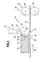
- FIG. 1 An embodiment of a device according to the invention for the production electrochemical or electrical or thermal functional layers, which is shown schematically in FIG. 1 and designated there as a whole by 10 is an application station 12 comprising a roller 14 as an example an application device for applying (dry) powder particles 16 on a carrier 18.
- the (application) roller 14 is rotatably mounted about an axis 20.
- the axis 20 is substantially parallel to the support 18 at least in an application area 22 aligned.
- the roller 14 is in particular a photo-roll, with which the Powder particles 16 can be xerographically applied to the carrier 18.
- the roller 14 is electrostatically charged.
- By exposure by means of an exposure device 24 can be defined surface areas of the charged Unload roller 14. It can thereby be on the surface of the roller 14 a create defined pattern on charged and uncharged areas, where then the roller 14 supplied powder particles according to this pattern at the Roll surface adhere and when transferring the powder particles on the Carrier 18, the pattern is displayed on the support 18.
- it can be a negative or positive image, depending on whether the powder particles on the roller 14 to the charged or uncharged Stick to areas. This depends on the powder material. Usually adhere powder particles at the charged sites.
- the exposed by the exposure device 24 areas 26 of Surface of the roller 14 are, for example, by a control device adjustable, so that the application pattern of the powder particles on the carrier 18 is adjustable.
- the exposure device 24 is arranged so that the electromagnetic Radiation 28, with which the exposure device 24 on the roller 14th acts outside of a powder feed to the roller 14, the roller 14 is reached.
- the roller 14 powder particles in shape a powder cloud 30 are supplied.
- the roller 14 is in a region 32 exposed to a powder cloud, then powder particles from the powder cloud adhere to the roller 14 according to the surface charge pattern there stay.
- the powder particles are from the powder cloud directly onto the roller 14th transfer.
- a feeder 34 for powder particles to the Roller 14 is provided.
- the delivery device is in fluidly effective communication with a powder supply (not shown in the drawing) and / or with a powder manufacturing apparatus (not shown in the figure).
- a powder manufacturing apparatus not shown in the figure.
- the Powder production device may be, for example, a homogenizer act, as described in DE 101 54 123 A1.
- the feeding device 34 a Powder delivery device comprises, as described in EP 1 273 354 A2 is. It is advantageously a gas stream at least not directly on the Roller 14 directed.
- the delivery device has a mouth opening 36, which the Roller 14 faces and in particular the region 32 of the roller facing is.
- the mouth opening 36 is formed and in particular in their shape adapted to the roller 14 that the proportion of powder particles, which emerges from the mouth opening 36 and does not reach the roller 14, is minimized.
- an outer end 38 of the mouth opening 36 is cylindrical circular arc-shaped designed and adapted to the cylindrical shape of the roller 14th
- the formed in the feeder 34 at the mouth opening 36 or guided to the mouth opening 36 powder cloud 30 then acts the roller 14, so that powder particles from the roller 14 on the surface thereof can be taken over.
- the carrier 18 is locally stationary and the Application station 12 is translationally moved relative to the carrier 18. Conveniently, however, it is provided that the application station 12 locally is stationary and the carrier 18 in a direction of movement 40 relative to the Application station 12 is moved. To move the carrier 18 in the direction of movement 40 corresponding transport rollers are provided (in the Drawing not shown).
- a fixing station 42 with a fixing device 44 may be provided.
- the fixing device 44 includes, for example a first fixing roller 46 disposed on one side of the carrier is, and a second fixing roller 48, which opposite to the other side of the carrier is arranged.
- the carrier 18 with applied Powder particles can be carried out between the two fixing rollers 46, 48.
- the two fixing rollers 46, 48 rotate in opposite directions, the first fixing roller 46 disposed on the same side of the carrier 18 Like the roller 14, it is rotated in the same direction as the roller 14.
- the amount of rotational speeds of the rollers 14, 46 and 48 is in essentially the same.
- the two fixing rollers 46, 48 can also serve as transport rollers.
- At least one of the fixing rollers (and preferably the fixing roller 46, which directly on the powder particles acts) is heated to improve the fixation effect.
- the feeding device 34 Via the feeding device 34 is a surface area of the roller 14th exposed to a powder cloud 30, d. H. This surface is made with powder particles acted upon in a powder cloud 30. Depending on the powder, the powder particles remain at electrostatically charged or uncharged areas of the roller 14 liable. The electrostatically uncharged areas were thereby over the Exposure device 24 generated.
- the adhering to the roller 14 powder particles are then rotated by the Transfer roller 14 to carrier 18; on the support 18 is then a corresponding powder particle layer is formed.
- This powder particle layer can be fixed via the fixing device 44.
- none of the roller 14 is upstream Transfer roller provided for powder particles.
- Solution can be powder even with a very small mean particle diameter (such as on the order of 30 nm) a carrier 18 transmitted.
- the solution according to the invention makes it possible to just to use powder with a small average particle size. Let it thereby form structures on a carrier 18 with better resolution. In addition, the loss of powder during the application process can be minimize.
- the corresponding application device 10 can be compact form.
- the applicator may, for example, instead of a roller a plate which is exposed to the powder cloud. The plate is then with adhering powder particles on the carrier 18 moves.
- the method according to the invention and the device according to the invention can be electrochemical functional layers such as Produce reaction layers for a fuel cell. It can be so multi-dimensional Form reaction layers with fine structures.
- FIG. 2 Another embodiment of a device according to the invention for Production of electrochemical or electrical or thermal Layers, which are shown in Figure 2 and designated there as a whole 110 , comprises a plurality of application stations 112, via the powder particles can be applied to a support 114.
- the application stations 112 are preferably arranged stationary and the Carrier 114 can be moved past these application stations 112 and, for example feasible through this.
- the carrier 114 is for example about Transport rollers moved in a direction of movement 116.
- each application station 118a, 118b, 118c and 118d lie in a row in the direction of movement 116 next to each other, d. H. behind each other, so that when transporting the carrier 114 to the application stations 118a, 118b, 118c, 118d past in succession at each application station 118a, 118b, 118c, 118d powder particles to a certain area of the Carrier 114 can be applied.
- an exemplary construction of an application station 112 is based on the application station 118a explained.
- This comprises an applicator 120, over which Powder particles are transferable to the carrier 114.
- an applicator 120 over which Powder particles are transferable to the carrier 114.
- one is (Application) roller as applicator 120 is provided.
- the roller 120 is rotatably mounted, wherein a corresponding axis of rotation 122 parallel to a is arranged to be coated surface of the carrier 114.
- the direction of rotation the roller 120 is such that its peripheral speed on the carrier 114 is parallel to the direction of movement 116 of the carrier 114.
- the roller 120 is or is electrostatically charged.
- she is considered Photo roller formed with a photosensitive surface 124.
- the application station 118a further comprises an exposure device 126, via which a surface area of the roller 120 can be illuminated. The surface area or the surface areas that are lit, let set yourself defined.
- a control device 128 is provided, about which just the exposed areas are spatially adjustable.
- the roller 120 is unloaded at the surface.
- the illumination setting of the control device 128 can therefore be at the surface 124 of the roller 120 defines electrostatically charged and set electrostatically uncharged areas.
- the roller 120 is fed to powder 130. This is a feeding device 132 provided.
- the feeder 132 provides powder to the roller 120 ready, which then adheres to the surface 124 and at chestrotation is transferred from the roller 120 to the carrier 114.
- the pattern of the powder particles on the surface 124 of the roller 120 becomes through the pattern of charged and discharged areas on the surface 124 of the roller 120 and thus adjusted by the controller 128th adjusted by means of the exposure device 126.
- the electrostatic charged or loadable Roller opposite a corona wire 134, and in particular on the other side of the carrier 114 is located, that is on the side, which faces away from the application side.
- the feeder 132 has for this purpose an orifice opening 136, which faces the roller 120 is.
- the mouth opening 136 can be adapted to the shape of the roller 120th be adjusted.
- a region of the roller 120 which defined by the exposure means 126 with charged and discharged Was prepared, apply to a powder cloud. Of the corresponding area is thus exposed to a powder cloud. From the mouth opening 136 powder particles in the form of a powder cloud directly on transfer the roller 120. Via the feed device 132 with the mouth opening 136, which assigns to the roller 120 and the roller 120 directly opposite, so can the roller 120 act on a powder cloud.
- the powder particles from the powder cloud directly the Roller 120 is supplied.
- none of the roller 120 is upstream Transfer roller provided for powder particles.
- Powder with very small mean diameters such as smaller than 1 ⁇ m and in particular of the order of 30 nm
- just powder with a small average particle size to use. This in turn allows structures on the Form carrier 114 with high resolution.
- an application device by means of a Plate is formed, which is or is electrostatically charged and which Powder particles are supplied. From the plate then powder particles on transmit the carrier 114.
- a certain area of the carrier 114 passes through the application station 118a. It is then further transported to the nearest application station 118b. This is basically the same design as just using the application station 118a described.
- a powder material A can be on the carrier 114, wherein the application is spatially controlled, that is, defined areas can be set on the carrier 114 which powder particles of the powder A are applied or not applied become.
- a similar process can then be done by the application station 118b are performed with a powder B, in which case again defined Spaces are adjustable.
- An exposure device of the application station 118b is coupled to the controller 128 accordingly.
- a powder C and through the application station 118d apply a powder D to the carrier 114.
- This layer 138 has regions 140 (FIGS. 3 (a) and (b)), in FIG where the powder particles of the powder A, B, C, D spatially defined are.
- a fixing device 142 For fixing an applied layer, a fixing device 142 be provided, which, for example, opposite fixing rollers 144 and 146, between which the carrier 114 is feasible.
- the Fixation rollers rotate in particular in opposite directions. You can simultaneously as transport rollers for transporting the carrier 114 in the direction of movement 116 serve.
- At least one of the fixing rollers 144, 146 is heated.
- a charging device 148 is provided. about this can be the carrier 114 charge electrically. About a charge of Carrier 114 may affect its properties under certain circumstances become.
- the charging device 148 comprises an electrostatic loaded roller 150, on which the carrier 114 is passed.
- the roller 150 may have a counter electrode, for example in the form of a Corona wire 152 are opposite.
- the carrier is between the roller 150 and the corona wire 152.
- the charging device 148 is the downstream application station 118d and the fixing device 142nd upstream. It is also possible in principle that a charging device before and / or after an application station 112 is arranged.
- Electrochemical Layers can be considered as electrochemical layers without material turnover
- electrochemical Produce reaction layers can be graded electrochemical Produce reaction layers.
- Microstructure reaction layer for example, next to a Catalyst particle is a proton-conducting particle is set.
- individual Controllability of the individual application stations 112 can be such defined spatial structure, which in turn to defined - also local - Chemical and physical properties leads produce.
Landscapes
- Engineering & Computer Science (AREA)
- Manufacturing & Machinery (AREA)
- Chemical & Material Sciences (AREA)
- Chemical Kinetics & Catalysis (AREA)
- Electrochemistry (AREA)
- General Chemical & Material Sciences (AREA)
- Application Of Or Painting With Fluid Materials (AREA)
- Inert Electrodes (AREA)
- Secondary Cells (AREA)
- Laminated Bodies (AREA)
- Coating Apparatus (AREA)
- Battery Electrode And Active Subsutance (AREA)
Abstract
Description
- Figur 1
- eine schematische Darstellung eines Ausführungsbeispiels einer erfindungsgemäßen Vorrichtung zur Herstellung von elektrochemischen oder elektrischen oder thermischen Schichten;
- Figur 2
- eine schematische Darstellung eines weiteren Ausführungsbeispiels einer erfindungsgemäßen Vorrichtung; und
- Figur 3(a)
- eine schematische Darstellung einer auf einem Träger hergestellten Schicht; und
- Figur 3(b)
- einen schematischen vergrößerten Ausschnitt aus der Schicht gemäß Figur 3(a), angedeutet durch die Lupe in Figur 3(a).
Claims (39)
- Verfahren zur Herstellung von elektrochemischen oder elektrischen oder thermischen Funktionsschichten mittels Pulvermaterialien, bei dem Pulverpartikel mittels einer Aufbringeinrichtung auf einen Träger aufgebracht werden,
dadurch gekennzeichnet , daß der Aufbringeinrichtung die Pulverpartikel in Form einer Pulverwolke zugeführt werden. - Verfahren nach Anspruch 1, dadurch gekennzeichnet, daß ein Bereich der Aufbringeinrichtung mit einer Pulverwolke beaufschlagt wird.
- Verfahren nach Anspruch 1 oder 2, dadurch gekennzeichnet, daß die Aufbringeinrichtung der Pulverwolke ausgesetzt wird.
- Verfahren nach einem der vorangehenden Ansprüche, dadurch gekennzeichnet, daß Pulver aus einem Pulvervorrat und/oder einer Pulverherstellungsvorrichtung direkt der Aufbringeinrichtung zugeführt wird.
- Verfahren nach einem der vorangehenden Ansprüche, dadurch gekennzeichnet, daß von einer Mündungsöffnung einer Pulverzuführungsvorrichtung aus Pulverpartikel direkt auf die Aufbringeinrichtung übertragen werden.
- Verfahren nach einem der vorangehenden Ansprüche, dadurch gekennzeichnet, daß von der Aufbringeinrichtung Pulverpartikel auf den Träger übertragen werden.
- Verfahren nach einem der vorangehenden Ansprüche, dadurch gekennzeichnet, daß die Aufbringeinrichtung elektrostatisch geladen ist oder wird.
- Verfahren nach Anspruch 7, dadurch gekennzeichnet, daß auf der Aufbringeinrichtung definierte geladene und/oder ungeladene Bereiche erzeugt sind oder werden.
- Verfahren nach einem der vorangehenden Ansprüche, dadurch gekennzeichnet, daß die Aufbringeinrichtung mittels einer Walze gebildet wird.
- Verfahren nach Anspruch 9, dadurch gekennzeichnet, daß die Walze eine Fotowalze ist.
- Verfahren nach einem der Ansprüche 1 bis 8, dadurch gekennzeichnet, daß die Aufbringeinrichtung eine Platte umfaßt.
- Verfahren nach einem der vorangehenden Ansprüche, dadurch gekennzeichnet, daß auf den Träger aufgebrachte Pulverpartikel fixiert werden.
- Verfahren nach Anspruch 12, dadurch gekennzeichnet, daß die Fixierung durch Walzung erfolgt.
- Verfahren nach einem der vorangehenden Ansprüche, dadurch gekennzeichnet, daß der Träger an einer Mehrzahl von Aufbringstationen zur Aufbringung von Pulverpartikeln auf den Träger vorbeigeführt wird und an den einzelnen Aufbringstationen die Aufbringung von Pulverpartikeln auf den Träger individuell räumlich gesteuert wird.
- Verfahren nach Anspruch 14, dadurch gekennzeichnet, daß die Aufbringstationen in einer Reihe angeordnet sind.
- Verfahren nach Anspruch 14 oder 15, dadurch gekennzeichnet, daß jeder Aufbringstation Pulver individuell zugeführt wird.
- Verfahren nach einem der Ansprüche 14 bis 16, dadurch gekennzeichnet, daß eine jeweilige Aufbringstation eine Aufbringeinrichtung aufweist, welcher Pulver zugeführt wird.
- Verfahren nach einem der Ansprüche 14 bis 17, dadurch gekennzeichnet, daß über unterschiedliche Aufbringstationen unterschiedliche Pulvermaterialien auf den Träger aufgebracht werden.
- Verfahren nach einem der Ansprüche 14 bis 18, dadurch gekennzeichnet, daß durch das Vorbeiführen des Trägers an den Aufbringstationen eine elektrochemische oder elektrische oder thermische Schicht mit räumlich definierter Zusammensetzung aus Pulverpartikeln hergestellt wird.
- Verfahren nach einem der vorangehenden Ansprüche, dadurch gekennzeichnet, daß die chemischen und physikalischen Eigenschaften der Schicht durch Steuerung der Pulveraufbringung eingestellt werden.
- Verfahren nach einem der vorangehenden Ansprüche, dadurch gekennzeichnet, daß der Träger aufgeladen wird.
- Vorrichtung zur Herstellung von elektrochemischen oder elektrischen oder thermischen Schichten aus Pulvermaterialien auf einem Träger, mit einer Aufbringeinrichtung (14) zum Übertragen von Pulverpartikeln (16) auf den Träger (18) und einer Zuführungsvorrichtung (34) für Pulver zu der Aufbringeinrichtung (14), dadurch gekennzeichnet, daß über die Zuführungsvorrichtung (34) die Aufbringeinrichtung (14) mit einer Pulverwolke (30) beaufschlagbar ist.
- Vorrichtung nach Anspruch 22, dadurch gekennzeichnet, daß die Zuführungsvorrichtung (34) eine Mündungsöffnung (36) umfaßt, welche auf die Aufbringeinrichtung (14) zu weist.
- Vorrichtung nach Anspruch 23, dadurch gekennzeichnet, daß die Mündungsöffnung (36) der Aufbringeinrichtung (14) direkt gegenüberliegt.
- Vorrichtung nach Anspruch 23 oder 24, dadurch gekennzeichnet, daß die Mündungsöffnung (36) in ihrer Gestalt an die Aufbringeinrichtung (14) angepaßt ist.
- Vorrichtung nach einem der Ansprüche 22 bis 25, dadurch gekennzeichnet, daß die Zuführungsvorrichtung (34) und/oder eine Mündungsöffnung (36) der Zuführungsvorrichtung (34) in fluidwirksamer Verbindung mit einem Pulvervorrat und/oder einer Pulverherstellungsvorrichtung steht.
- Vorrichtung nach einem der Ansprüche 22 bis 26, dadurch gekennzeichnet, daß die Aufbringeinrichtung (14) elektrostatisch geladen ist oder geladen werden kann.
- Vorrichtung nach Anspruch 27, dadurch gekennzeichnet, daß definierte Bereiche (26) der Aufbringeinrichtung (14) elektrostatisch ladbar und/oder entladbar sind.
- Vorrichtung nach einem der Ansprüche 22 bis 28, dadurch gekennzeichnet, daß die Aufbringeinrichtung mittels einer Walze (14) gebildet ist.
- Vorrichtung nach Anspruch 29, dadurch gekennzeichnet, daß die Walze (14) als Fotowalze ausgebildet ist.
- Vorrichtung nach einem der Ansprüche 22 bis 27, dadurch gekennzeichnet, daß die Aufbringeinrichtung eine Platte umfaßt.
- Vorrichtung nach einem der Ansprüche 22 bis 31, dadurch gekennzeichnet, daß eine Fixierungseinrichtung (44) zur Fixierung von auf den Träger (18) aufgebrachten Pulverpartikeln vorgesehen ist.
- Vorrichtung nach Anspruch 32, dadurch gekennzeichnet, daß die Fixierungseinrichtung eine oder mehrere Fixierungswalzen (46; 48) umfaßt.
- Vorrichtung nach einem der Ansprüche 22 bis 33, dadurch gekennzeichnet, daß eine Mehrzahl von Aufbringstationen (112) vorgesehen ist, an welchen der Träger (114) vorbeiführbar ist, wobei die Pulveraufbringung an jeder Aufbringstation (112) individuell steuerbar ist.
- Vorrichtung nach Anspruch 34, dadurch gekennzeichnet, daß die Aufbringstationen (112) nebeneinander angeordnet sind.
- Vorrichtung nach Anspruch 34 oder 35, dadurch gekennzeichnet, daß die Pulveraufbringung in jeder Aufbringstation (112) räumlich steuerbar ist.
- Vorrichtung nach einem der Ansprüche 34 bis 36, dadurch gekennzeichnet, daß jeder Aufbringstation (112) individuell Pulver zuführbar ist.
- Vorrichtung nach einem der Ansprüche 34 bis 37, dadurch gekennzeichnet, daß eine einzelne Aufbringstation (112) eine Aufbringeinrichtung (120) umfaßt, mittels welcher Pulverpartikel auf den Träger (114) übertragbar sind.
- Vorrichtung nach einem der Ansprüche 22 bis 38, dadurch gekennzeichnet, daß eine Aufladungseinrichtung (148) zur elektrischen Aufladung des Trägers (114) vorgesehen ist.
Applications Claiming Priority (4)
| Application Number | Priority Date | Filing Date | Title |
|---|---|---|---|
| DE102004017161 | 2004-03-31 | ||
| DE102004017161A DE102004017161A1 (de) | 2004-03-31 | 2004-03-31 | Pulverpartikel-Aufbringverfahren und Aufbringvorrichtung für Pulverpartikel |
| DE102004017162A DE102004017162A1 (de) | 2004-03-31 | 2004-03-31 | Verfahren und Vorrichtung zur Herstellung von elektrochemischen oder elektrischen oder thermischen Schichten |
| DE102004017162 | 2004-03-31 |
Publications (2)
| Publication Number | Publication Date |
|---|---|
| EP1582266A1 true EP1582266A1 (de) | 2005-10-05 |
| EP1582266B1 EP1582266B1 (de) | 2008-11-05 |
Family
ID=34888832
Family Applications (1)
| Application Number | Title | Priority Date | Filing Date |
|---|---|---|---|
| EP05005674A Expired - Lifetime EP1582266B1 (de) | 2004-03-31 | 2005-03-16 | Verfahren und Vorrichtung zur Herstellung von elektrochemischen oder elektrischen oder thermischen Funktionsschichten |
Country Status (5)
| Country | Link |
|---|---|
| EP (1) | EP1582266B1 (de) |
| AT (1) | ATE413231T1 (de) |
| DE (1) | DE502005005845D1 (de) |
| DK (1) | DK1582266T3 (de) |
| PT (1) | PT1582266E (de) |
Citations (4)
| Publication number | Priority date | Publication date | Assignee | Title |
|---|---|---|---|---|
| GB1161430A (en) * | 1965-10-20 | 1969-08-13 | Bethlehem Steel Corp | Strip Coating Method and Apparatus |
| US5738905A (en) * | 1995-03-17 | 1998-04-14 | Deutsche Forschungsanstalt Fuer Luft- Und Raumfahrt E.V. | Process for the production of a composite comprising electrode material, catalyst material and a solid-electrolyte membrane |
| US20020187258A1 (en) * | 2000-05-24 | 2002-12-12 | Nordson Corporation | Electrostatic fluidized bed coating method and apparatus |
| EP1273354A2 (de) * | 2001-07-02 | 2003-01-08 | Deutsches Zentrum für Luft- und Raumfahrt e.V. | Pulverfördervorrichtung und Verfahren zur Pulverauftragung auf einen Träger |
-
2005
- 2005-03-16 AT AT05005674T patent/ATE413231T1/de not_active IP Right Cessation
- 2005-03-16 DK DK05005674T patent/DK1582266T3/da active
- 2005-03-16 EP EP05005674A patent/EP1582266B1/de not_active Expired - Lifetime
- 2005-03-16 DE DE502005005845T patent/DE502005005845D1/de not_active Expired - Lifetime
- 2005-03-16 PT PT05005674T patent/PT1582266E/pt unknown
Patent Citations (4)
| Publication number | Priority date | Publication date | Assignee | Title |
|---|---|---|---|---|
| GB1161430A (en) * | 1965-10-20 | 1969-08-13 | Bethlehem Steel Corp | Strip Coating Method and Apparatus |
| US5738905A (en) * | 1995-03-17 | 1998-04-14 | Deutsche Forschungsanstalt Fuer Luft- Und Raumfahrt E.V. | Process for the production of a composite comprising electrode material, catalyst material and a solid-electrolyte membrane |
| US20020187258A1 (en) * | 2000-05-24 | 2002-12-12 | Nordson Corporation | Electrostatic fluidized bed coating method and apparatus |
| EP1273354A2 (de) * | 2001-07-02 | 2003-01-08 | Deutsches Zentrum für Luft- und Raumfahrt e.V. | Pulverfördervorrichtung und Verfahren zur Pulverauftragung auf einen Träger |
Also Published As
| Publication number | Publication date |
|---|---|
| ATE413231T1 (de) | 2008-11-15 |
| DE502005005845D1 (de) | 2008-12-18 |
| EP1582266B1 (de) | 2008-11-05 |
| PT1582266E (pt) | 2008-12-18 |
| DK1582266T3 (da) | 2009-01-19 |
Similar Documents
| Publication | Publication Date | Title |
|---|---|---|
| EP1037295B1 (de) | Verfahren zum Aufbringen von Elektrodenschichten auf eine bandförmige Polymerelektrolytmembran für Brennstoffzellen | |
| EP1239528B1 (de) | Verfahren zur Herstellung einer mehrschichtigen Elektrode oder Membran-Elektrodenverbundeinheit, und Gasdiffusionselektrode | |
| DE10243100B4 (de) | Verfahren und Vorrichtungen zur Herstellung von Membranelektroden für Brennstoffzellen | |
| DE19509748C2 (de) | Verfahren zur Herstellung eines Verbundes aus Elektrodenmaterial, Katalysatormaterial und einer Festelektrolytmembran | |
| DE112005000257T5 (de) | Verfahren und Vorrichtung zur Ausbildung einer Katalysatorschicht auf einem Substrat, welches eine Membran-Elektrodenanordnung bildet | |
| EP0655030A1 (de) | Verfahren und vorrichtung zum befeuchten einer bedruckten und anschliessend thermsich getrockneten, bewegten materialbahn. | |
| DE19548422A1 (de) | Materialverbunde und ihre kontinuierliche Herstellung | |
| DE102008019864B3 (de) | Verfahren zum elektrochemischen Beschichten eines Substrates durch Brush Plating und Vorrichtung zur Durchführung dieses Verfahrens | |
| EP4398324A1 (de) | Vorrichtung und verfahren zur herstellung einer elektrode | |
| WO2011039009A2 (de) | Verfahren zum elektrochemischen beschichten eines substrates durch brush plating und vorrichtung zur durchführung dieses verfahrens | |
| EP1321197B1 (de) | Verfahren und Vorrichtung zur Beschichtung von bewegten Substraten | |
| EP1095187A1 (de) | Verfahren und vorrichtung zur verbesserung einer strichoberfläche von papierbahnen | |
| EP1582266B1 (de) | Verfahren und Vorrichtung zur Herstellung von elektrochemischen oder elektrischen oder thermischen Funktionsschichten | |
| WO2020007677A1 (de) | Verfahren und vorrichtung zum herstellen einer bipolarplattenhälfte für eine brennstoffzelle | |
| DE112005002734B4 (de) | Verfahren und Vorrichtung zum Herstellen einer Elektrodenschicht für eine Brennstoffzelle | |
| DE102021107621A1 (de) | Verfahren zur Beschichtung eines Trägermaterials mit einem Aktivmaterial zur Herstellung einer Elektrodenfolie einer Batteriezelle | |
| EP4435880A1 (de) | Prozessanordnung sowie verfahren zur fertigung einer elektrode | |
| DE19940015B9 (de) | Verfahren und Vorrichtung zur Herstellung einer Elektrode | |
| DE10056535C2 (de) | Brennstoffzellenanordnung | |
| EP1683583B1 (de) | Verfahren und Vorrichtung zur Pulverbeschichtung | |
| DE102013007199A1 (de) | Membranelektrodenanordnung und Brennstoffzelle | |
| DE102004058474B4 (de) | Verfahren zur Herstellung einer Elektroden-Elektrolyt-Struktur | |
| WO2025219357A1 (de) | Vereinfachtes wachstum von nanodrähten | |
| WO2025242264A1 (de) | Verfahren zum assemblieren einer dünnschichteinheit und anlage | |
| WO2025224301A1 (de) | Optimiertes beschichtungsverfahren |
Legal Events
| Date | Code | Title | Description |
|---|---|---|---|
| PUAI | Public reference made under article 153(3) epc to a published international application that has entered the european phase |
Free format text: ORIGINAL CODE: 0009012 |
|
| AK | Designated contracting states |
Kind code of ref document: A1 Designated state(s): AT BE BG CH CY CZ DE DK EE ES FI FR GB GR HU IE IS IT LI LT LU MC NL PL PT RO SE SI SK TR |
|
| AX | Request for extension of the european patent |
Extension state: AL BA HR LV MK YU |
|
| 17P | Request for examination filed |
Effective date: 20060315 |
|
| AKX | Designation fees paid |
Designated state(s): AT BE BG CH CY CZ DE DK EE ES FI FR GB GR HU IE IS IT LI LT LU MC NL PL PT RO SE SI SK TR |
|
| RAP1 | Party data changed (applicant data changed or rights of an application transferred) |
Owner name: DEUTSCHES ZENTRUM FUER LUFT- UND RAUMFAHRT E.V. |
|
| GRAP | Despatch of communication of intention to grant a patent |
Free format text: ORIGINAL CODE: EPIDOSNIGR1 |
|
| GRAS | Grant fee paid |
Free format text: ORIGINAL CODE: EPIDOSNIGR3 |
|
| GRAA | (expected) grant |
Free format text: ORIGINAL CODE: 0009210 |
|
| AK | Designated contracting states |
Kind code of ref document: B1 Designated state(s): AT BE BG CH CY CZ DE DK EE ES FI FR GB GR HU IE IS IT LI LT LU MC NL PL PT RO SE SI SK TR |
|
| REG | Reference to a national code |
Ref country code: GB Ref legal event code: FG4D Free format text: NOT ENGLISH |
|
| REG | Reference to a national code |
Ref country code: CH Ref legal event code: EP |
|
| REG | Reference to a national code |
Ref country code: IE Ref legal event code: FG4D Free format text: LANGUAGE OF EP DOCUMENT: GERMAN |
|
| REF | Corresponds to: |
Ref document number: 502005005845 Country of ref document: DE Date of ref document: 20081218 Kind code of ref document: P |
|
| REG | Reference to a national code |
Ref country code: PT Ref legal event code: SC4A Free format text: AVAILABILITY OF NATIONAL TRANSLATION Effective date: 20081204 |
|
| REG | Reference to a national code |
Ref country code: DK Ref legal event code: T3 |
|
| NLV1 | Nl: lapsed or annulled due to failure to fulfill the requirements of art. 29p and 29m of the patents act | ||
| LTIE | Lt: invalidation of european patent or patent extension |
Effective date: 20081105 |
|
| PG25 | Lapsed in a contracting state [announced via postgrant information from national office to epo] |
Ref country code: ES Free format text: LAPSE BECAUSE OF FAILURE TO SUBMIT A TRANSLATION OF THE DESCRIPTION OR TO PAY THE FEE WITHIN THE PRESCRIBED TIME-LIMIT Effective date: 20090216 Ref country code: LT Free format text: LAPSE BECAUSE OF FAILURE TO SUBMIT A TRANSLATION OF THE DESCRIPTION OR TO PAY THE FEE WITHIN THE PRESCRIBED TIME-LIMIT Effective date: 20081105 |
|
| PG25 | Lapsed in a contracting state [announced via postgrant information from national office to epo] |
Ref country code: SI Free format text: LAPSE BECAUSE OF FAILURE TO SUBMIT A TRANSLATION OF THE DESCRIPTION OR TO PAY THE FEE WITHIN THE PRESCRIBED TIME-LIMIT Effective date: 20081105 Ref country code: IS Free format text: LAPSE BECAUSE OF FAILURE TO SUBMIT A TRANSLATION OF THE DESCRIPTION OR TO PAY THE FEE WITHIN THE PRESCRIBED TIME-LIMIT Effective date: 20090305 Ref country code: FI Free format text: LAPSE BECAUSE OF FAILURE TO SUBMIT A TRANSLATION OF THE DESCRIPTION OR TO PAY THE FEE WITHIN THE PRESCRIBED TIME-LIMIT Effective date: 20081105 Ref country code: NL Free format text: LAPSE BECAUSE OF FAILURE TO SUBMIT A TRANSLATION OF THE DESCRIPTION OR TO PAY THE FEE WITHIN THE PRESCRIBED TIME-LIMIT Effective date: 20081105 Ref country code: PL Free format text: LAPSE BECAUSE OF FAILURE TO SUBMIT A TRANSLATION OF THE DESCRIPTION OR TO PAY THE FEE WITHIN THE PRESCRIBED TIME-LIMIT Effective date: 20081105 |
|
| REG | Reference to a national code |
Ref country code: IE Ref legal event code: FD4D |
|
| PG25 | Lapsed in a contracting state [announced via postgrant information from national office to epo] |
Ref country code: IE Free format text: LAPSE BECAUSE OF FAILURE TO SUBMIT A TRANSLATION OF THE DESCRIPTION OR TO PAY THE FEE WITHIN THE PRESCRIBED TIME-LIMIT Effective date: 20081105 Ref country code: EE Free format text: LAPSE BECAUSE OF FAILURE TO SUBMIT A TRANSLATION OF THE DESCRIPTION OR TO PAY THE FEE WITHIN THE PRESCRIBED TIME-LIMIT Effective date: 20081105 Ref country code: RO Free format text: LAPSE BECAUSE OF FAILURE TO SUBMIT A TRANSLATION OF THE DESCRIPTION OR TO PAY THE FEE WITHIN THE PRESCRIBED TIME-LIMIT Effective date: 20081105 Ref country code: BG Free format text: LAPSE BECAUSE OF FAILURE TO SUBMIT A TRANSLATION OF THE DESCRIPTION OR TO PAY THE FEE WITHIN THE PRESCRIBED TIME-LIMIT Effective date: 20090205 |
|
| PG25 | Lapsed in a contracting state [announced via postgrant information from national office to epo] |
Ref country code: SE Free format text: LAPSE BECAUSE OF FAILURE TO SUBMIT A TRANSLATION OF THE DESCRIPTION OR TO PAY THE FEE WITHIN THE PRESCRIBED TIME-LIMIT Effective date: 20090205 Ref country code: CZ Free format text: LAPSE BECAUSE OF FAILURE TO SUBMIT A TRANSLATION OF THE DESCRIPTION OR TO PAY THE FEE WITHIN THE PRESCRIBED TIME-LIMIT Effective date: 20081105 |
|
| PLBE | No opposition filed within time limit |
Free format text: ORIGINAL CODE: 0009261 |
|
| STAA | Information on the status of an ep patent application or granted ep patent |
Free format text: STATUS: NO OPPOSITION FILED WITHIN TIME LIMIT |
|
| BERE | Be: lapsed |
Owner name: DEUTSCHES ZENTRUM FUR LUFT- UND RAUMFAHRT E.V. Effective date: 20090331 |
|
| PG25 | Lapsed in a contracting state [announced via postgrant information from national office to epo] |
Ref country code: SK Free format text: LAPSE BECAUSE OF FAILURE TO SUBMIT A TRANSLATION OF THE DESCRIPTION OR TO PAY THE FEE WITHIN THE PRESCRIBED TIME-LIMIT Effective date: 20081105 |
|
| 26N | No opposition filed |
Effective date: 20090806 |
|
| PG25 | Lapsed in a contracting state [announced via postgrant information from national office to epo] |
Ref country code: MC Free format text: LAPSE BECAUSE OF NON-PAYMENT OF DUE FEES Effective date: 20090331 |
|
| REG | Reference to a national code |
Ref country code: CH Ref legal event code: PL |
|
| PG25 | Lapsed in a contracting state [announced via postgrant information from national office to epo] |
Ref country code: LI Free format text: LAPSE BECAUSE OF NON-PAYMENT OF DUE FEES Effective date: 20090331 Ref country code: CH Free format text: LAPSE BECAUSE OF NON-PAYMENT OF DUE FEES Effective date: 20090331 |
|
| PG25 | Lapsed in a contracting state [announced via postgrant information from national office to epo] |
Ref country code: BE Free format text: LAPSE BECAUSE OF NON-PAYMENT OF DUE FEES Effective date: 20090331 |
|
| PG25 | Lapsed in a contracting state [announced via postgrant information from national office to epo] |
Ref country code: AT Free format text: LAPSE BECAUSE OF NON-PAYMENT OF DUE FEES Effective date: 20090316 |
|
| PG25 | Lapsed in a contracting state [announced via postgrant information from national office to epo] |
Ref country code: GR Free format text: LAPSE BECAUSE OF FAILURE TO SUBMIT A TRANSLATION OF THE DESCRIPTION OR TO PAY THE FEE WITHIN THE PRESCRIBED TIME-LIMIT Effective date: 20090206 |
|
| PG25 | Lapsed in a contracting state [announced via postgrant information from national office to epo] |
Ref country code: IT Free format text: LAPSE BECAUSE OF FAILURE TO SUBMIT A TRANSLATION OF THE DESCRIPTION OR TO PAY THE FEE WITHIN THE PRESCRIBED TIME-LIMIT Effective date: 20081105 |
|
| PG25 | Lapsed in a contracting state [announced via postgrant information from national office to epo] |
Ref country code: LU Free format text: LAPSE BECAUSE OF NON-PAYMENT OF DUE FEES Effective date: 20090316 |
|
| PG25 | Lapsed in a contracting state [announced via postgrant information from national office to epo] |
Ref country code: HU Free format text: LAPSE BECAUSE OF FAILURE TO SUBMIT A TRANSLATION OF THE DESCRIPTION OR TO PAY THE FEE WITHIN THE PRESCRIBED TIME-LIMIT Effective date: 20090506 |
|
| PG25 | Lapsed in a contracting state [announced via postgrant information from national office to epo] |
Ref country code: TR Free format text: LAPSE BECAUSE OF FAILURE TO SUBMIT A TRANSLATION OF THE DESCRIPTION OR TO PAY THE FEE WITHIN THE PRESCRIBED TIME-LIMIT Effective date: 20081105 |
|
| PG25 | Lapsed in a contracting state [announced via postgrant information from national office to epo] |
Ref country code: CY Free format text: LAPSE BECAUSE OF FAILURE TO SUBMIT A TRANSLATION OF THE DESCRIPTION OR TO PAY THE FEE WITHIN THE PRESCRIBED TIME-LIMIT Effective date: 20081105 |
|
| REG | Reference to a national code |
Ref country code: FR Ref legal event code: PLFP Year of fee payment: 11 |
|
| REG | Reference to a national code |
Ref country code: DE Ref legal event code: R082 Ref document number: 502005005845 Country of ref document: DE Representative=s name: HOEGER, STELLRECHT & PARTNER PATENTANWAELTE MB, DE |
|
| REG | Reference to a national code |
Ref country code: FR Ref legal event code: PLFP Year of fee payment: 12 |
|
| REG | Reference to a national code |
Ref country code: FR Ref legal event code: PLFP Year of fee payment: 13 |
|
| REG | Reference to a national code |
Ref country code: FR Ref legal event code: PLFP Year of fee payment: 14 |
|
| REG | Reference to a national code |
Ref country code: DE Ref legal event code: R082 Ref document number: 502005005845 Country of ref document: DE Representative=s name: HOEGER, STELLRECHT & PARTNER PATENTANWAELTE MB, DE |
|
| PGFP | Annual fee paid to national office [announced via postgrant information from national office to epo] |
Ref country code: GB Payment date: 20200228 Year of fee payment: 16 Ref country code: DK Payment date: 20200226 Year of fee payment: 16 Ref country code: DE Payment date: 20200214 Year of fee payment: 16 Ref country code: PT Payment date: 20200226 Year of fee payment: 16 |
|
| PGFP | Annual fee paid to national office [announced via postgrant information from national office to epo] |
Ref country code: FR Payment date: 20200219 Year of fee payment: 16 |
|
| REG | Reference to a national code |
Ref country code: DE Ref legal event code: R119 Ref document number: 502005005845 Country of ref document: DE |
|
| REG | Reference to a national code |
Ref country code: DK Ref legal event code: EBP Effective date: 20210331 |
|
| GBPC | Gb: european patent ceased through non-payment of renewal fee |
Effective date: 20210316 |
|
| PG25 | Lapsed in a contracting state [announced via postgrant information from national office to epo] |
Ref country code: PT Free format text: LAPSE BECAUSE OF NON-PAYMENT OF DUE FEES Effective date: 20210916 |
|
| PG25 | Lapsed in a contracting state [announced via postgrant information from national office to epo] |
Ref country code: DE Free format text: LAPSE BECAUSE OF NON-PAYMENT OF DUE FEES Effective date: 20211001 Ref country code: GB Free format text: LAPSE BECAUSE OF NON-PAYMENT OF DUE FEES Effective date: 20210316 Ref country code: FR Free format text: LAPSE BECAUSE OF NON-PAYMENT OF DUE FEES Effective date: 20210331 |
|
| PG25 | Lapsed in a contracting state [announced via postgrant information from national office to epo] |
Ref country code: DK Free format text: LAPSE BECAUSE OF NON-PAYMENT OF DUE FEES Effective date: 20210331 |