EP1582235A1 - Implantable medical device - Google Patents
Implantable medical device Download PDFInfo
- Publication number
- EP1582235A1 EP1582235A1 EP05003645A EP05003645A EP1582235A1 EP 1582235 A1 EP1582235 A1 EP 1582235A1 EP 05003645 A EP05003645 A EP 05003645A EP 05003645 A EP05003645 A EP 05003645A EP 1582235 A1 EP1582235 A1 EP 1582235A1
- Authority
- EP
- European Patent Office
- Prior art keywords
- slot
- housing
- medical device
- implantable medical
- electrically conductive
- Prior art date
- Legal status (The legal status is an assumption and is not a legal conclusion. Google has not performed a legal analysis and makes no representation as to the accuracy of the status listed.)
- Granted
Links
- 239000004020 conductor Substances 0.000 claims abstract description 47
- 238000002560 therapeutic procedure Methods 0.000 claims description 29
- 230000005855 radiation Effects 0.000 claims description 16
- 239000003989 dielectric material Substances 0.000 claims description 13
- 238000001465 metallisation Methods 0.000 claims description 9
- 239000000919 ceramic Substances 0.000 claims description 8
- 230000007704 transition Effects 0.000 claims description 6
- 230000005672 electromagnetic field Effects 0.000 claims description 4
- 239000007769 metal material Substances 0.000 claims description 3
- 230000005684 electric field Effects 0.000 description 8
- 239000000463 material Substances 0.000 description 5
- 238000004891 communication Methods 0.000 description 4
- NOESYZHRGYRDHS-UHFFFAOYSA-N insulin Chemical compound N1C(=O)C(NC(=O)C(CCC(N)=O)NC(=O)C(CCC(O)=O)NC(=O)C(C(C)C)NC(=O)C(NC(=O)CN)C(C)CC)CSSCC(C(NC(CO)C(=O)NC(CC(C)C)C(=O)NC(CC=2C=CC(O)=CC=2)C(=O)NC(CCC(N)=O)C(=O)NC(CC(C)C)C(=O)NC(CCC(O)=O)C(=O)NC(CC(N)=O)C(=O)NC(CC=2C=CC(O)=CC=2)C(=O)NC(CSSCC(NC(=O)C(C(C)C)NC(=O)C(CC(C)C)NC(=O)C(CC=2C=CC(O)=CC=2)NC(=O)C(CC(C)C)NC(=O)C(C)NC(=O)C(CCC(O)=O)NC(=O)C(C(C)C)NC(=O)C(CC(C)C)NC(=O)C(CC=2NC=NC=2)NC(=O)C(CO)NC(=O)CNC2=O)C(=O)NCC(=O)NC(CCC(O)=O)C(=O)NC(CCCNC(N)=N)C(=O)NCC(=O)NC(CC=3C=CC=CC=3)C(=O)NC(CC=3C=CC=CC=3)C(=O)NC(CC=3C=CC(O)=CC=3)C(=O)NC(C(C)O)C(=O)N3C(CCC3)C(=O)NC(CCCCN)C(=O)NC(C)C(O)=O)C(=O)NC(CC(N)=O)C(O)=O)=O)NC(=O)C(C(C)CC)NC(=O)C(CO)NC(=O)C(C(C)O)NC(=O)C1CSSCC2NC(=O)C(CC(C)C)NC(=O)C(NC(=O)C(CCC(N)=O)NC(=O)C(CC(N)=O)NC(=O)C(NC(=O)C(N)CC=1C=CC=CC=1)C(C)C)CC1=CN=CN1 NOESYZHRGYRDHS-UHFFFAOYSA-N 0.000 description 4
- 239000002184 metal Substances 0.000 description 4
- 238000000034 method Methods 0.000 description 4
- 230000000747 cardiac effect Effects 0.000 description 3
- 102000004877 Insulin Human genes 0.000 description 2
- 108090001061 Insulin Proteins 0.000 description 2
- 230000005540 biological transmission Effects 0.000 description 2
- 229910010293 ceramic material Inorganic materials 0.000 description 2
- 229940125396 insulin Drugs 0.000 description 2
- 238000004519 manufacturing process Methods 0.000 description 2
- 230000002411 adverse Effects 0.000 description 1
- 239000008280 blood Substances 0.000 description 1
- 210000004369 blood Anatomy 0.000 description 1
- 239000003990 capacitor Substances 0.000 description 1
- 230000008859 change Effects 0.000 description 1
- 230000008878 coupling Effects 0.000 description 1
- 238000010168 coupling process Methods 0.000 description 1
- 238000005859 coupling reaction Methods 0.000 description 1
- 238000010017 direct printing Methods 0.000 description 1
- 230000005670 electromagnetic radiation Effects 0.000 description 1
- 238000005530 etching Methods 0.000 description 1
- 239000011521 glass Substances 0.000 description 1
- 230000001939 inductive effect Effects 0.000 description 1
- 238000002347 injection Methods 0.000 description 1
- 239000007924 injection Substances 0.000 description 1
- 230000002452 interceptive effect Effects 0.000 description 1
- 238000000059 patterning Methods 0.000 description 1
- 230000010287 polarization Effects 0.000 description 1
- 230000008569 process Effects 0.000 description 1
- 238000007789 sealing Methods 0.000 description 1
- 238000000926 separation method Methods 0.000 description 1
Images



Classifications
-
- A—HUMAN NECESSITIES
- A61—MEDICAL OR VETERINARY SCIENCE; HYGIENE
- A61N—ELECTROTHERAPY; MAGNETOTHERAPY; RADIATION THERAPY; ULTRASOUND THERAPY
- A61N1/00—Electrotherapy; Circuits therefor
- A61N1/18—Applying electric currents by contact electrodes
- A61N1/32—Applying electric currents by contact electrodes alternating or intermittent currents
- A61N1/36—Applying electric currents by contact electrodes alternating or intermittent currents for stimulation
- A61N1/372—Arrangements in connection with the implantation of stimulators
- A61N1/37211—Means for communicating with stimulators
- A61N1/37217—Means for communicating with stimulators characterised by the communication link, e.g. acoustic or tactile
- A61N1/37223—Circuits for electromagnetic coupling
- A61N1/37229—Shape or location of the implanted or external antenna
-
- A—HUMAN NECESSITIES
- A61—MEDICAL OR VETERINARY SCIENCE; HYGIENE
- A61N—ELECTROTHERAPY; MAGNETOTHERAPY; RADIATION THERAPY; ULTRASOUND THERAPY
- A61N1/00—Electrotherapy; Circuits therefor
- A61N1/18—Applying electric currents by contact electrodes
- A61N1/32—Applying electric currents by contact electrodes alternating or intermittent currents
- A61N1/36—Applying electric currents by contact electrodes alternating or intermittent currents for stimulation
- A61N1/372—Arrangements in connection with the implantation of stimulators
- A61N1/375—Constructional arrangements, e.g. casings
Definitions
- the present invention relates to an implantable medical device.
- Telemetry is used to e.g. change or modify operation characteristics of the implantable device or to readout data from the implantable medical device to monitor its function or to achieve information of the patient having the device implanted.
- Telemetry systems for implantable medical devices utilize radio-frequency energy to enable communication between the implantable device and an external programmer device.
- US 2002/0095195 A1 discloses an implantable medical device utilizing such far-field electromagnetic radiation to allow communication over a large distance.
- Two conductive halves of a housing for the implantable device act as a dipole antenna for radiating and receiving far-field radio frequency radiation modulated with telemetry data.
- US 2002/0095195 A1 discloses a manner to utilize the limited space for the antenna function, but, nevertheless, there are several limitations of using an implantable medical device, in which two separated conductive halves of the housing act as a dipole antenna.
- a header made of dielectric material between the two conductive halves, thereby admitting external interfering radiation to enter the implantable device and interfere with signals transmitted within any of the two conductive halves or with signals transmitted across the dielectric header.
- the design of the implantable medical device does not allow for an optimum location of the therapy leads with respect to potential interference of the therapy signals by radio frequency signals fed to or received by the dipole antenna.
- the antenna type lacks a voltage node on its surface, where the electric field has a minimum, thereby affecting the therapy signals to a minimum extent.
- a further object of the invention is to provide such an implantable medical device, which is shielded from external radio frequency radiation in any direction.
- a still further object of the invention is to provide such an implantable medical device, which has a minimum number of feed-throughs in the housing thereof.
- a yet further object of the invention is to provide such an implantable medical device, which is provided with therapy lines protruding from the implantable medical device, where the therapy lines are located so as to be affected as little as possible by radiation transmitted and/or received by the antenna of the implantable medical device.
- a still further object of the invention is to provide such an implantable medical device, in which the antenna is easy to manufacture to a low cost, easy to tune, and which antenna enables an efficient use of available space.
- a yet further object of the invention is to provide such an implantable medical device, which is reliable, and particularly mechanically durable.
- Implantable medical devices as claimed in the appended patent claims attain these objects, among others.
- an implantable medical device comprising a housing; electric circuitry for the operation of the implantable medical device; and radio frequency circuitry for transmitting and/or receiving radio frequency signals, wherein the electric circuitry and the radio frequency circuitry are interconnected and arranged within the housing, and the implantable medical device has at least a surface portion made of an electrically conductive material, preferably a metallic material. At least one slot is provided in the surface portion of the electrically conductive material; and a slot feeding is operatively interconnected between the radio frequency circuitry and the slot, wherein the surface portion of the electrically conductive material provided with the slot is adapted to operate as a transmitting and/or receiving antenna for the radio frequency signals.
- the surface portion of an electrically conductive material may advantageously be a surface portion such as a portion of or the complete housing, or a portion of a dielectric header, which is metallized.
- the surface portion of the electrically conductive material is located internally within the housing.
- the surface portion may be made of sheet metal.
- the housing is an electrically conductive housing
- the entire housing with the slot can be tailored to operate as an antenna for the radio frequency telemetry signals without any requirement of an insulating separation.
- the electric circuitry, the radio frequency circuitry, and the interconnection there between are enclosed by the electrically conductive housing to shield the electric circuitry, the radio frequency circuitry, and the interconnection from external radiation in any direction.
- therapy lines such as those used in a cardiac pacemaker device, they are advantageously arranged to protrude from the housing close to a voltage node of an electromagnetic field as obtained when the surface portion of the electrically conductive material operates as an antenna for the radio frequency telemetry signals. Such provision provides for a minimum interference between the therapy lines and the antenna function.
- a slot which is open in one end thereof and which in the antenna literature often is referred to as a notch antenna; a slot which is closed in both ends thereof and which is preferably provided with a backing cavity; and a slot which is closed in both ends thereof and which is formed as a through-hole to extend across the complete thickness of the implantable medical device.
- slot feeding Several types of slot feeding are known in the antenna literature and some of them are suitable to be used in the present invention.
- a conductor crossing the slot an inductive coupling loop within the slot, a conductor crossing a portion of the slot and connected capacitively to the opposite edge of the slot, or a feeding including a kind of coaxial or wire feed-to-waveguide transition can be used.
- the latter feeding can preferably be used when the slot is provided with a backing cavity, where the backing cavity operates as a waveguide to feed the slot.
- the antenna of the present invention is operable to transmit or receive radio frequency signals. Even if a term is used herein that suggests one specific signal direction it is to be appreciated that such a situation can cover that signal direction and/or its reverse.
- the implantable medical device may e.g. be a pacemaker, an insulin dispenser or other medical equipment including a telemetry link, preferably a high frequency telemetry link.
- the implantable medical device comprises an electrically conductive hollow housing 1, electric circuitry 3 for the operation of the implantable medical device, and radio frequency circuitry 5 for transmitting and/or receiving radio telemetry frequency signals.
- the electric circuitry 3 and the radio frequency circuitry 5 are interconnected 7 and are arranged in the electrically conductive housing in a common space or in separate compartments, which may be shielded from each other.
- the electrically conductive housing 1 is provided with a slot 10, and feed conductors 11, 13 are interconnected between the radio frequency circuitry 5 and edges 15, 17 of the slot 10.
- the electrically conductive housing can be adapted to operate as an antenna for the radio frequency telemetry signals.
- the slot 10 is open in one end thereof to form what is usually referred to as a shunt or notch antenna in the antenna literature, see e.g. R.C. Johnson, Antenna Engineering Handbook, third edition, McGraw-Hill, 1993, pages 37-14 - 37-17, the content of which being hereby incorporated by reference.
- This kind of antenna has been used extensively on aircrafts.
- the length of the slot should nominally be ⁇ /4 to obtain resonance, where ⁇ is the effective wavelength in the dielectric material in the slot. The length can be different if tuning components are included.
- the slot is open so that blood and surrounding tissue may fill out the slot.
- the dielectric constant of such matter may vary considerably, which naturally affect the resonance frequency or wavelength of the antenna.
- the dielectric material is not important for the radiation performance as such, but tunes the resonance to a lower frequency than the one indicated by the physical length.
- a dielectric constant of 1 a quarter of an effective wavelength to obtain resonance measures 18 cm, whereas at a dielectric constant of 65 the resonant slot length is 2.3 cm.
- a dielectric constant of 1 gives a resonant ⁇ /4 length of 3.1 cm
- a dielectric constant of 65 gives a resonant ⁇ /4 length of 0.39 cm.
- the electric circuitry 3, the radio frequency circuitry 5, and the interconnection 7 are enclosed by the electrically conductive housing 1 so that the electric circuitry 3, the radio frequency circuitry 5, and the interconnection 7 are shielded from external radio frequency radiation in any direction.
- the electrically conductive housing 1 operates similarly to a Faraday cage to effectively hinder radio frequency radiation from entering the housing.
- the conductive housing 1 may have openings of a size, which depends on the frequency of the radiation that shall be shielded.
- the electrically conductive housing 1 is typically sealed, particularly hermetically sealed, sealed feed-throughs are required.
- One of the feed conductors 13 is therefore provided with a hermetic feed-through 19 in the electrically conductive housing 1 so that the feed conductor 13 can protrude from one of the edges 15 of the electrically conductive housing 1, and extend across the slot 10 to be connected at the opposite edge 17 of the slot 10 to create an electric field within the slot 10 by flowing a feeding current in the feed conductor 13.
- the feed conductors are center 13 and shield 11 conductors of a coaxial cable, where the center conductor 13 is connected at the opposite edge 17 of the slot 10.
- the conductor may, however, be thicker than an ordinary center conductor of a coaxial cable in the slot 10.
- the feeding of the antenna may be implemented in any manner known in the art, e.g. using balanced feed or unbalanced feed, and using any kind of antenna tuning circuit or impedance matching network (not illustrated), which loads the antenna with a variable amount of inductance or capacitance to thereby adjust the effective electrical length of the antenna and match the antenna impedance to the impedance of the transmitter/receiver.
- the reactance of the antenna may be tuned out so that the antenna forms a resonant structure at the specified carrier frequency and efficiently transmits/receives far-field radio frequency radiation.
- radiation-affecting components may be arranged across the slot 10.
- Capacitors, inductors, or active components may be interconnected between the edges 15, 17 of the slot 10. Capacitances may be implemented as small protrusions at the edges 15, 17 of the slot 10, whereas inductors may be implemented as narrow strips across slot 10.
- the design of the impedance matching network and the slot 10 can be chosen in order to obtain suitable antenna performance in terms of radiation parameters such as resonance frequency, input impedance, bandwidth, radiation pattern, gain, polarization and near-field pattern.
- Another way to control the feeding impedance is to move the location of the feed conductor 13 along the slot 10.
- the radiation parameters can be controlled to accommodate for different filling materials in the slot, which have different dielectric properties.
- the feed conductor 13 does not necessarily have to cross the slot in its entire width.
- the feed conductor 13 may for instance make a loop in the slot and be connected to the same slot edge, at which it is fed through the electrically conductive housing 1.
- the slot 10 in the Figs. 1a-b is located substantially halfway between two oppositely located edges of the electrically conductive housing, i.e. so that extensions, of the electrically conductive housing 1 on either side of the slot in directions orthogonal to the slot 10, schematically indicated by arrows 21, 23, are of similar sizes.
- Such location of the slot provides for capabilities to obtain an optimum antenna performance. A location closer to the circumference of the housing 1 will gradually make the impedance matching more difficult.
- Figs. 2a-b illustrate a second embodiment of the implantable medical device wherein the device is provided with two output therapy lines 25 connected to the electric circuitry 3, where each of the therapy lines 25 is provided with a hermetic feed-through 27.
- the protrusions of the therapy lines 25 are only schematically indicated in Figs. 2a-b and it shall be appreciated by the person skilled in the art that they may be longer.
- the therapy lines 25 may have different shape and be different in number.
- the therapy lines 25 should preferably be located where they have as small influence on the antenna function as possible. This is useful both to avoid influence on the therapy function and to avoid the therapy lines to operate as antennas.
- an electromagnetic field calculation is typically performed, and one result of such a calculation is the electric field around the implantable medical device, which will give hints for suitable locations.
- the therapy lines 25 are located in the slot 10, preferably symmetrically in the slot, where the electric field has a minimum.
- An alternative location is at an opposite edge of the electrically conductive housing 1.
- the shape of the housing 1 may be less regular than what is illustrated in Figs. 2a-b, but still a position on the circumference of the housing 1 can be found, where a local minimum of the electric field exists.
- the slot 10 is filled with a dielectric material 31, particularly a plastic, a glass or a ceramic material. This gives on one hand a well-defined dielectric constant of the material 31 in the slot, and on the other hand a good support for the therapy lines 25.
- the device comprises as above an electrically conductive housing 1, in which electric circuitry 3, and radio frequency circuitry 5 are interconnected. Feed conductors 11, 13 are interconnected between the radio frequency circuitry 5 and edges 15, 17 of the slot, which in this embodiment has different shape, and is therefore denoted by 30.
- the slot 30 is closed in both ends 33, 35 thereof and the antenna thus formed is commonly referred to as a slot or aperture antenna.
- a slot antenna is an elongated aperture in a conducting surface where one or more feeding elements generate an electric field over the elongated aperture.
- the slot 30 is preferably half an effective wavelength ( ⁇ /2) long to achieve a resonant structure, but a shorter slot will radiate as well but with gradually larger impedance matching problems. A very short slot will also have a narrower instantaneous bandwidth.
- the shape is not critical for the antenna function and for instance rounded and wider ends, a so-called dumbbell shape, is frequently used to decrease the resonant length.
- the slot 30 there is provided electric shielding or circuitry (schematically indicated at 40 in Fig. 3b) to prevent the slot from radiating inwards in the housing 1 to affect the circuitry therein in an adverse manner.
- the tissue of the body, which surrounds the implantable medical device, has typically a high electric constant, thereby reducing the length of the ⁇ /2 slot. This also reduces the amount of radiation directed to the interior of the housing 1.
- Fig. 4 illustrates a fourth preferred embodiment of the implantable medical device, which is identical with the Figs. 3a-b embodiment except of that the slot 30 is filled with dielectric material 31 having a known dielectric constant.
- Fig. 5 illustrates a fifth preferred embodiment of the implantable medical device wherein the slot is what is referred to as a cavity-backed slot 50, and comprises a backing cavity 41 below the slot 30 instead of the shielding 40.
- this embodiment is identical with the Figs. 3a-b embodiment.
- the backing cavity 41 at the inside of the housing 1 is a rather large structure; it may measure ⁇ /2 times ⁇ /4- ⁇ /2, where ⁇ is the effective wavelength in the filling material of the backing cavity 41, if any.
- the antenna is a cavity resonator fed energized by a feed conductor connected across the slot (not illustrated), which radiates from the slot aperture. Further reference to cavity-backed slot antennas is given in R.C. Johnson, Antenna Engineering Handbook, third edition, McGraw-Hill, 1993, pages 8-7 - 8-9, the content of which being hereby incorporated by reference.
- the backing cavity can be turned to be e.g. parallel with the surface of the housing 1, in which the thin slot is made.
- a turned cavity 41' for backing of the slot 30 is illustrated.
- the cavity can be filled with a ceramic material, which is partly metallized and welded or brazed to the electrically conductive housing to form a hermetic sealing.
- the feeding of the slot 30 can include a coaxial feed-to-waveguide transition.
- the center conductor 13 of the coaxial feeding is connected through a hole in the ceramic to an edge of the slot 30, whereas the shield conductor 11 is connected to the metallized ceramic.
- the ceramic should not be metallized in the slot 30.
- the length of the cavity 41' is preferably about a quarter of an effective wavelength to obtain high impedance at the slot 30.
- FIG. 7 an alternative feeding of the turned cavity-backed slot 50 is shown.
- a bottom end of the cavity, here denoted 41" is provided with a second slot 42.
- a wire 13', possibly on a printed circuit board 43, below the second slot 42 can be adapted to feed the second slot 42 to obtain a wire feed-to-waveguide transition. If the ceramic has a high dielectric constant the second slot 42 will be too short to radiate towards the electric circuitry in the housing 1.
- a ground connector 11' or similar of the printed circuit board 43 is conveniently connected to the metallized portion of the ceramic-filled cavity 41''.
- the device comprises as above an electrically conductive housing 1, in which electric circuitry 3, and radio frequency circuitry 5 are interconnected. Feed conductors 11, 13 are interconnected between the radio frequency circuitry 5 and edges 15, 17 of the slot, which in this embodiment is a through hole 80 through the complete thickness of the housing 1. This eliminates the need of a cavity.
- the through hole 80 is filled with dielectric material (not illustrated).
- Fig. 9 illustrates a seventh preferred embodiment of the implantable medical device wherein the device is provided with a therapy line 25 protruding from the housing 1 via a hermetic feed-through 27.
- the therapy line 25 is connected to the electric circuitry of the implantable medical device (not illustrated in Fig. 9 for sake of simplicity).
- the therapy line 25 protrudes from the housing 1 at a position along an extension line 29 of the slot 80.
- this embodiment is identical with the Figs. 8a-b embodiment.
- the therapy line 25 shall protrude from the housing 1 close to a voltage node of an electromagnetic field as obtained when the electrically conductive housing 1 operates as the antenna for the radio frequency signals.
- a voltage node can be found by calculating or measuring the electric field generated by the implantable medical device.
- equipotential surfaces of the electric field are denoted by 44.
- Fig. 10 illustrates an eighth preferred embodiment of the implantable medical device.
- the hermetically sealed hollow housing 100 houses as in the other preferred embodiments electric circuitry, radio frequency circuitry, an interconnection between them, and antenna feed conductors (not explicitly illustrated).
- the housing 100 may be of an electrically conductive material or of a dielectric material such as e.g. a ceramic. Further, a header 101 is mounted to the housing 100, wherein the header is of a dielectric material and is advantageously a molded component, e.g. an injection molded part.
- the header 101 supports two therapy lines 103, which are connected to the electric circuitry in the housing 100 via hermetic feed-throughs in the wall of the housing 100.
- a portion of or the complete surface of the header 101 is covered by metal, preferably in a process known as metallization, and a slot antenna 107 is formed in the metallized surface, e.g. by means of patterning and etching.
- the patterned metallization with the slot 107 is formed by some kind of direct printing technique.
- any of the different slots described in this description may be used in this embodiment: a slot which is closed in both ends thereof and which is optionally provided with a backing cavity, a slot which is closed in both ends thereof and which is formed as a through-hole to extend across the complete thickness of the header 101, and a notch antenna.
- the header 101 has naturally to be formed to include a through hole or a notch structure, before the surface is metallized.
- the feed conductors are advantageously connected to the antenna in any of the manners as described in connection with the descriptions of the other preferred embodiments of the invention.
- a hermetic feed-through for the feed conductors is provided in the wall of the housing 100.
- the metallization of the header 101 is advantageously electrically connected to the housing 100.
- Fig. 11 illustrates a ninth preferred embodiment of the implantable medical device.
- the housing or cover, here denoted by 110 is of a material, which is not electrically conductive, such as e.g. a ceramic or a plastic.
- the electric circuitry and the radio frequency may be arranged separately in shielded and/or hermetically sealed compartments within the housing 110, or together in a single compartment. If they are arranged in separate compartments hermetic feed throughs are needed for the connection between them. If the circuitry is arranged in a hermetically sealed environment, the housing 110 itself does not necessarily have to be hermetically sealed.
- the housing 110 could for instance be molded.
- the implantable medical device has according to the present invention a surface portion 112 made of an electrically conductive material, preferably a metal, wherein a slot 114 is provided in the surface portion 112 made of the electrically conductive material.
- a slot feeding is operatively interconnected between the radio frequency circuitry and the slot 114, and the surface portion 112 made of the electrically conductive material provided with the slot 114 is adapted to operate as a transmitting and/or receiving antenna for radio frequency signals transmitted and/or received by the radio frequency circuitry.
- the slot feeding may e.g. be similar to any of those illustrated in Figs. 5-7.
- the surface portion 112 made of the electrically conductive material is an outer surface portion of the housing 110, and thus of the medical device.
- the conductive surface portion 112 with the slot 114 can be formed as a patterned metallization of e.g. one side of the housing 110.
- the conductive surface portion 112 is an internal surface within the housing 110. It may for instance be an outer surface of a metallic wall compartment within the housing 110, or a metallization of the surface of a dielectric wall compartment.
- the conductive surface portion 112 may be a piece of sheet metal, which is arranged within the housing 110.
- a large compartment or housing houses all components internal to the implantable medical device. It may be made of a metallic material or of a dielectric material, in which case a surface portion is metallized.
- the slot antenna of the invention is made in the wall of the compartment or housing, or in the metallized surface portion, and is connected as in any of the preferred embodiments above.
- the complete compartment or housing is then covered by a dielectric material, preferably a thin layer of the dielectric material, to obtain a medical device having an outer surface suitable to be implanted in a human being, and optionally to hermetically seal the medical device. Only therapy lines, if any, have to be capable of being connectable to the interior of the medical device.
- the slots in the embodiments as described above does not have to be formed along a straight line, but may have any suitable elongated shape.
- the slot-based antenna is used in the present invention i.a. as is it can be formed on a metallic structure, the shape of which may be determined by special requirements, and which should not be changed by the presence of the slot.
- the implantable medical device may be provided with two or more slots with separate feeding.
- such an implantable medical device may be adapted for transmitting and/or receiving radio frequency waves in at least two different frequency bands, e.g. both around 400 MHz and around 2.4 GHz.
Landscapes
- Health & Medical Sciences (AREA)
- Engineering & Computer Science (AREA)
- Biomedical Technology (AREA)
- Nuclear Medicine, Radiotherapy & Molecular Imaging (AREA)
- Radiology & Medical Imaging (AREA)
- Life Sciences & Earth Sciences (AREA)
- Animal Behavior & Ethology (AREA)
- General Health & Medical Sciences (AREA)
- Public Health (AREA)
- Veterinary Medicine (AREA)
- Physics & Mathematics (AREA)
- Electromagnetism (AREA)
- Acoustics & Sound (AREA)
- Electrotherapy Devices (AREA)
Abstract
Description
- The present invention relates to an implantable medical device.
- In an implantable medical device, such as a cardiac pacemaker, an implantable cardioverter/defibrillator, or an insulin dispenser, telemetry is used to e.g. change or modify operation characteristics of the implantable device or to readout data from the implantable medical device to monitor its function or to achieve information of the patient having the device implanted. Telemetry systems for implantable medical devices utilize radio-frequency energy to enable communication between the implantable device and an external programmer device.
- Earlier telemetry systems used a rather low radio frequency, i.e. 8-300 kHz, as a carrier wavelength for communication between an antenna of the implantable device and an antenna of the external programmer device, which were inductively coupled to each other. Due to the very poor operating distance of this technique, the exterior antenna had to be located in close proximity to the implantable device, typically within a few inches. Further, the communication suffered from low transmission data rate.
- Recently, telemetry systems using a radio frequency data link operating at a much higher frequency, around 400 MHz, have been proposed, which enable two improvements to be made. Firstly, the antenna efficiency can be improved allowing extended range between the pacemaker and the external antenna. Secondly, the transmission data rate can be improved. Even higher frequencies can be used such as those within the ISM-band at 2400-2485.5 MHz.
- US 2002/0095195 A1 discloses an implantable medical device utilizing such far-field electromagnetic radiation to allow communication over a large distance. Two conductive halves of a housing for the implantable device act as a dipole antenna for radiating and receiving far-field radio frequency radiation modulated with telemetry data. An insulating header, in which therapy leads can be located, separates the conductive halves.
- US 2002/0095195 A1 discloses a manner to utilize the limited space for the antenna function, but, nevertheless, there are several limitations of using an implantable medical device, in which two separated conductive halves of the housing act as a dipole antenna.
- Firstly, there is arranged a header made of dielectric material between the two conductive halves, thereby admitting external interfering radiation to enter the implantable device and interfere with signals transmitted within any of the two conductive halves or with signals transmitted across the dielectric header.
- Secondly, in order to hermetically seal the two housing halves, a number of feed-throughs between them are needed since different electric circuitry is located in different housing halves to effectively use the available space.
- Thirdly, the design of the implantable medical device does not allow for an optimum location of the therapy leads with respect to potential interference of the therapy signals by radio frequency signals fed to or received by the dipole antenna. The antenna type lacks a voltage node on its surface, where the electric field has a minimum, thereby affecting the therapy signals to a minimum extent.
- Finally, the mechanical structure of the prior art implantable medical device seems not to be optimum: two housing portions of a conductive material have to produced, and to be fixed to and hermetically sealed against an intermediate piece of dielectric material. The manufacturing is made further complicated by the need of a number of feed-throughs.
- It is thus an object of the present invention to provide an implantable medical device provided with an antenna that overcomes the above-mentioned problems.
- In this respect there is a particular object of the invention to provide such an implantable medical device, which exhibits an overall improved antenna performance in comparison with implantable medical devices of the prior art. Higher antenna efficiency implies increased usable range for an exterior antenna.
- A further object of the invention is to provide such an implantable medical device, which is shielded from external radio frequency radiation in any direction.
- A still further object of the invention is to provide such an implantable medical device, which has a minimum number of feed-throughs in the housing thereof.
- A yet further object of the invention is to provide such an implantable medical device, which is provided with therapy lines protruding from the implantable medical device, where the therapy lines are located so as to be affected as little as possible by radiation transmitted and/or received by the antenna of the implantable medical device.
- A still further object of the invention is to provide such an implantable medical device, in which the antenna is easy to manufacture to a low cost, easy to tune, and which antenna enables an efficient use of available space.
- A yet further object of the invention is to provide such an implantable medical device, which is reliable, and particularly mechanically durable.
- Implantable medical devices as claimed in the appended patent claims attain these objects, among others.
- According to an aspect of the present invention there is provided an implantable medical device comprising a housing; electric circuitry for the operation of the implantable medical device; and radio frequency circuitry for transmitting and/or receiving radio frequency signals, wherein the electric circuitry and the radio frequency circuitry are interconnected and arranged within the housing, and the implantable medical device has at least a surface portion made of an electrically conductive material, preferably a metallic material. At least one slot is provided in the surface portion of the electrically conductive material; and a slot feeding is operatively interconnected between the radio frequency circuitry and the slot, wherein the surface portion of the electrically conductive material provided with the slot is adapted to operate as a transmitting and/or receiving antenna for the radio frequency signals.
- The surface portion of an electrically conductive material may advantageously be a surface portion such as a portion of or the complete housing, or a portion of a dielectric header, which is metallized. Alternatively, the surface portion of the electrically conductive material is located internally within the housing. The surface portion may be made of sheet metal.
- If the housing is an electrically conductive housing, the entire housing with the slot can be tailored to operate as an antenna for the radio frequency telemetry signals without any requirement of an insulating separation.
- Further, the electric circuitry, the radio frequency circuitry, and the interconnection there between are enclosed by the electrically conductive housing to shield the electric circuitry, the radio frequency circuitry, and the interconnection from external radiation in any direction.
- If therapy lines, such as those used in a cardiac pacemaker device, are provided, they are advantageously arranged to protrude from the housing close to a voltage node of an electromagnetic field as obtained when the surface portion of the electrically conductive material operates as an antenna for the radio frequency telemetry signals. Such provision provides for a minimum interference between the therapy lines and the antenna function.
- Three different general principles regarding the shape and location of the slot is described: a slot which is open in one end thereof and which in the antenna literature often is referred to as a notch antenna; a slot which is closed in both ends thereof and which is preferably provided with a backing cavity; and a slot which is closed in both ends thereof and which is formed as a through-hole to extend across the complete thickness of the implantable medical device.
- Several types of slot feeding are known in the antenna literature and some of them are suitable to be used in the present invention. Depending on the kind of slot a conductor crossing the slot, an inductive coupling loop within the slot, a conductor crossing a portion of the slot and connected capacitively to the opposite edge of the slot, or a feeding including a kind of coaxial or wire feed-to-waveguide transition can be used. The latter feeding can preferably be used when the slot is provided with a backing cavity, where the backing cavity operates as a waveguide to feed the slot.
- Further characteristics of the invention and advantages thereof, will be evident from the following detailed description of preferred embodiments of the present invention given hereinafter and from the accompanying Figs. 1-11, which are given by way of illustration only, and shall thus not limit the scope of the present invention.
- In the description it is to be understood that the antenna of the present invention is operable to transmit or receive radio frequency signals. Even if a term is used herein that suggests one specific signal direction it is to be appreciated that such a situation can cover that signal direction and/or its reverse.
-
- Figs. 1a-b illustrate schematically, in a top view with a top cover removed, and in a side view, respectively, an implantable medical device according to a preferred embodiment of the present invention.
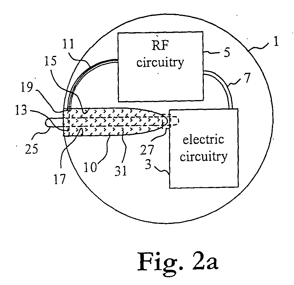
- Figs. 2a-b illustrate schematically, in a top view with a top cover removed, and in a side view, respectively, a further preferred embodiment of the implantable medical device according to the present invention.
- Figs. 3a-b illustrate schematically, in a top view with a top cover removed, and in a side view with a slot feeding removed, respectively, a still further preferred embodiment of the implantable medical device.
- Fig. 4 illustrates schematically, in a top view with a top cover removed, a yet further preferred embodiment of the implantable medical device.
- Fig. 5 illustrates schematically, in a side view with a slot feeding removed, a still further preferred embodiment of the implantable medical device.
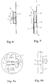
- Fig. 6 illustrates schematically, in a side view, an alternative embodiment of a slot feeding for use with the implantable medical device of Fig. 5.
- Fig. 7 illustrates schematically, in a side view, another alternative embodiment of a slot feeding for use with the implantable medical device of Fig. 5.
- Figs. 8a-b illustrate schematically, in a top view with a top cover removed, and in a side view, respectively, a yet further preferred embodiment of the implantable medical device.
- Figs. 9-11 illustrate schematically, in top views, still further preferred embodiments of the implantable medical device.
-
- Throughout the Figures similar parts and components, and portions thereof, are denoted by identical reference numerals.
- A first preferred embodiment of an implantable medical device of the present invention will be described with reference to Figs. 1a-b. The implantable medical device may e.g. be a pacemaker, an insulin dispenser or other medical equipment including a telemetry link, preferably a high frequency telemetry link.
- The implantable medical device comprises an electrically conductive
hollow housing 1,electric circuitry 3 for the operation of the implantable medical device, andradio frequency circuitry 5 for transmitting and/or receiving radio telemetry frequency signals. Theelectric circuitry 3 and theradio frequency circuitry 5 are interconnected 7 and are arranged in the electrically conductive housing in a common space or in separate compartments, which may be shielded from each other. - According to the present invention the electrically
conductive housing 1 is provided with aslot 10, and feedconductors radio frequency circuitry 5 and edges 15, 17 of theslot 10. By means of such provisions, the electrically conductive housing can be adapted to operate as an antenna for the radio frequency telemetry signals. - In the Figs. 1a-b embodiment the
slot 10 is open in one end thereof to form what is usually referred to as a shunt or notch antenna in the antenna literature, see e.g. R.C. Johnson, Antenna Engineering Handbook, third edition, McGraw-Hill, 1993, pages 37-14 - 37-17, the content of which being hereby incorporated by reference. This kind of antenna has been used extensively on aircrafts. The length of the slot should nominally be λ/4 to obtain resonance, where λ is the effective wavelength in the dielectric material in the slot. The length can be different if tuning components are included. - In Figs. 1a-b the slot is open so that blood and surrounding tissue may fill out the slot. The dielectric constant of such matter may vary considerably, which naturally affect the resonance frequency or wavelength of the antenna. The dielectric material is not important for the radiation performance as such, but tunes the resonance to a lower frequency than the one indicated by the physical length. At 400 MHz and a dielectric constant of 1, a quarter of an effective wavelength to obtain resonance measures 18 cm, whereas at a dielectric constant of 65 the resonant slot length is 2.3 cm. Correspondingly, at 2.4 GHz a dielectric constant of 1 gives a resonant λ/4 length of 3.1 cm, whereas a dielectric constant of 65 gives a resonant λ/4 length of 0.39 cm. All these slot lengths but the largest are easily feasible to use in a cardiac pacemaker device, which today typically measures about 3-8 cm in diameter. Also, there is a wide possibility to use shorter slots by suitable impedance matching. The use of a λ/4 slot as being illustrated in Figs. 1a-b is obviously preferred to keep the dimensions small, especially when a frequency around 400 MHz is used.
- Preferably, the
electric circuitry 3, theradio frequency circuitry 5, and theinterconnection 7 are enclosed by the electricallyconductive housing 1 so that theelectric circuitry 3, theradio frequency circuitry 5, and theinterconnection 7 are shielded from external radio frequency radiation in any direction. Hence, the electricallyconductive housing 1 operates similarly to a Faraday cage to effectively hinder radio frequency radiation from entering the housing. With respect to the shielding functionality theconductive housing 1 may have openings of a size, which depends on the frequency of the radiation that shall be shielded. As the electricallyconductive housing 1 is typically sealed, particularly hermetically sealed, sealed feed-throughs are required. - One of the
feed conductors 13 is therefore provided with a hermetic feed-through 19 in the electricallyconductive housing 1 so that thefeed conductor 13 can protrude from one of theedges 15 of the electricallyconductive housing 1, and extend across theslot 10 to be connected at theopposite edge 17 of theslot 10 to create an electric field within theslot 10 by flowing a feeding current in thefeed conductor 13. - Preferably, the feed conductors are
center 13 andshield 11 conductors of a coaxial cable, where thecenter conductor 13 is connected at theopposite edge 17 of theslot 10. The conductor may, however, be thicker than an ordinary center conductor of a coaxial cable in theslot 10. - The feeding of the antenna may be implemented in any manner known in the art, e.g. using balanced feed or unbalanced feed, and using any kind of antenna tuning circuit or impedance matching network (not illustrated), which loads the antenna with a variable amount of inductance or capacitance to thereby adjust the effective electrical length of the antenna and match the antenna impedance to the impedance of the transmitter/receiver. In this manner, the reactance of the antenna may be tuned out so that the antenna forms a resonant structure at the specified carrier frequency and efficiently transmits/receives far-field radio frequency radiation. Further, radiation-affecting components may be arranged across the
slot 10. Capacitors, inductors, or active components may be interconnected between theedges slot 10. Capacitances may be implemented as small protrusions at theedges slot 10, whereas inductors may be implemented as narrow strips acrossslot 10. - The design of the impedance matching network and the
slot 10 can be chosen in order to obtain suitable antenna performance in terms of radiation parameters such as resonance frequency, input impedance, bandwidth, radiation pattern, gain, polarization and near-field pattern. - Another way to control the feeding impedance is to move the location of the
feed conductor 13 along theslot 10. - Preferably, the radiation parameters can be controlled to accommodate for different filling materials in the slot, which have different dielectric properties.
- It shall be appreciated that the
feed conductor 13 does not necessarily have to cross the slot in its entire width. Thefeed conductor 13 may for instance make a loop in the slot and be connected to the same slot edge, at which it is fed through the electricallyconductive housing 1. - The
slot 10 in the Figs. 1a-b is located substantially halfway between two oppositely located edges of the electrically conductive housing, i.e. so that extensions, of the electricallyconductive housing 1 on either side of the slot in directions orthogonal to theslot 10, schematically indicated byarrows housing 1 will gradually make the impedance matching more difficult. - Figs. 2a-b illustrate a second embodiment of the implantable medical device wherein the device is provided with two
output therapy lines 25 connected to theelectric circuitry 3, where each of the therapy lines 25 is provided with a hermetic feed-through 27. The protrusions of thetherapy lines 25 are only schematically indicated in Figs. 2a-b and it shall be appreciated by the person skilled in the art that they may be longer. The therapy lines 25 may have different shape and be different in number. - The therapy lines 25 should preferably be located where they have as small influence on the antenna function as possible. This is useful both to avoid influence on the therapy function and to avoid the therapy lines to operate as antennas. In the antenna design procedure an electromagnetic field calculation is typically performed, and one result of such a calculation is the electric field around the implantable medical device, which will give hints for suitable locations. In order to thus minimize the interference the
therapy lines 25 are located in theslot 10, preferably symmetrically in the slot, where the electric field has a minimum. An alternative location is at an opposite edge of the electricallyconductive housing 1. The shape of thehousing 1 may be less regular than what is illustrated in Figs. 2a-b, but still a position on the circumference of thehousing 1 can be found, where a local minimum of the electric field exists. - Further, the
slot 10 is filled with adielectric material 31, particularly a plastic, a glass or a ceramic material. This gives on one hand a well-defined dielectric constant of the material 31 in the slot, and on the other hand a good support for the therapy lines 25. - A third preferred embodiment of the implantable medical device of the present invention will next be described with reference to Figs. 3a-b. The device comprises as above an electrically
conductive housing 1, in whichelectric circuitry 3, andradio frequency circuitry 5 are interconnected.Feed conductors radio frequency circuitry 5 and edges 15, 17 of the slot, which in this embodiment has different shape, and is therefore denoted by 30. Theslot 30 is closed in both ends 33, 35 thereof and the antenna thus formed is commonly referred to as a slot or aperture antenna. A slot antenna is an elongated aperture in a conducting surface where one or more feeding elements generate an electric field over the elongated aperture. - The
slot 30 is preferably half an effective wavelength (λ/2) long to achieve a resonant structure, but a shorter slot will radiate as well but with gradually larger impedance matching problems. A very short slot will also have a narrower instantaneous bandwidth. The shape is not critical for the antenna function and for instance rounded and wider ends, a so-called dumbbell shape, is frequently used to decrease the resonant length. - Below the
slot 30 there is provided electric shielding or circuitry (schematically indicated at 40 in Fig. 3b) to prevent the slot from radiating inwards in thehousing 1 to affect the circuitry therein in an adverse manner. The tissue of the body, which surrounds the implantable medical device, has typically a high electric constant, thereby reducing the length of the λ/2 slot. This also reduces the amount of radiation directed to the interior of thehousing 1. - Obviously, there is a natural transition from the λ/2 slot geometry of Figs. 3a-b to the λ/4 notch of Figs. 1a-b. Provided that the λ/4 notch is made in a thin structure it can be seen as a λ/2 slot, which is bent over the edge of the structure.
- Fig. 4 illustrates a fourth preferred embodiment of the implantable medical device, which is identical with the Figs. 3a-b embodiment except of that the
slot 30 is filled withdielectric material 31 having a known dielectric constant. - Fig. 5 illustrates a fifth preferred embodiment of the implantable medical device wherein the slot is what is referred to as a cavity-backed
slot 50, and comprises abacking cavity 41 below theslot 30 instead of the shielding 40. In other respects this embodiment is identical with the Figs. 3a-b embodiment. - The
backing cavity 41 at the inside of thehousing 1 is a rather large structure; it may measure λ/2 times λ/4-λ/2, where λ is the effective wavelength in the filling material of thebacking cavity 41, if any. The antenna is a cavity resonator fed energized by a feed conductor connected across the slot (not illustrated), which radiates from the slot aperture. Further reference to cavity-backed slot antennas is given in R.C. Johnson, Antenna Engineering Handbook, third edition, McGraw-Hill, 1993, pages 8-7 - 8-9, the content of which being hereby incorporated by reference. Depending on the dielectric constant of the filling material the depth of thecavity 41 will be different, but in the case the cavity should be deeper than the thickness of the implantable medical device, the backing cavity can be turned to be e.g. parallel with the surface of thehousing 1, in which the thin slot is made. - In Fig. 6 such a turned cavity 41' for backing of the
slot 30 is illustrated. The cavity can be filled with a ceramic material, which is partly metallized and welded or brazed to the electrically conductive housing to form a hermetic sealing. The feeding of theslot 30 can include a coaxial feed-to-waveguide transition. Thecenter conductor 13 of the coaxial feeding is connected through a hole in the ceramic to an edge of theslot 30, whereas theshield conductor 11 is connected to the metallized ceramic. The ceramic should not be metallized in theslot 30. The length of the cavity 41' is preferably about a quarter of an effective wavelength to obtain high impedance at theslot 30. - In Fig. 7 an alternative feeding of the turned cavity-backed
slot 50 is shown. A bottom end of the cavity, here denoted 41", is provided with asecond slot 42. A wire 13', possibly on a printedcircuit board 43, below thesecond slot 42 can be adapted to feed thesecond slot 42 to obtain a wire feed-to-waveguide transition. If the ceramic has a high dielectric constant thesecond slot 42 will be too short to radiate towards the electric circuitry in thehousing 1. A ground connector 11' or similar of the printedcircuit board 43 is conveniently connected to the metallized portion of the ceramic-filled cavity 41''. - A sixth preferred embodiment of the implantable medical device will next be described with reference to Figs. 8a-b. The device comprises as above an electrically
conductive housing 1, in whichelectric circuitry 3, andradio frequency circuitry 5 are interconnected.Feed conductors radio frequency circuitry 5 and edges 15, 17 of the slot, which in this embodiment is a throughhole 80 through the complete thickness of thehousing 1. This eliminates the need of a cavity. - It shall be appreciated by the man skilled in the art that in an alternative version of this embodiment, the through
hole 80 is filled with dielectric material (not illustrated). - Fig. 9 illustrates a seventh preferred embodiment of the implantable medical device wherein the device is provided with a
therapy line 25 protruding from thehousing 1 via a hermetic feed-through 27. Thetherapy line 25 is connected to the electric circuitry of the implantable medical device (not illustrated in Fig. 9 for sake of simplicity). Thetherapy line 25 protrudes from thehousing 1 at a position along anextension line 29 of theslot 80. In other respects this embodiment is identical with the Figs. 8a-b embodiment. - Generally, the
therapy line 25 shall protrude from thehousing 1 close to a voltage node of an electromagnetic field as obtained when the electricallyconductive housing 1 operates as the antenna for the radio frequency signals. Such a voltage node can be found by calculating or measuring the electric field generated by the implantable medical device. In Fig. 9 equipotential surfaces of the electric field are denoted by 44. - Fig. 10 illustrates an eighth preferred embodiment of the implantable medical device. The hermetically sealed
hollow housing 100 houses as in the other preferred embodiments electric circuitry, radio frequency circuitry, an interconnection between them, and antenna feed conductors (not explicitly illustrated). - The
housing 100 may be of an electrically conductive material or of a dielectric material such as e.g. a ceramic. Further, aheader 101 is mounted to thehousing 100, wherein the header is of a dielectric material and is advantageously a molded component, e.g. an injection molded part. - The
header 101 supports twotherapy lines 103, which are connected to the electric circuitry in thehousing 100 via hermetic feed-throughs in the wall of thehousing 100. - According to the present invention a portion of or the complete surface of the
header 101 is covered by metal, preferably in a process known as metallization, and aslot antenna 107 is formed in the metallized surface, e.g. by means of patterning and etching. Alternatively, the patterned metallization with theslot 107 is formed by some kind of direct printing technique. - Generally, any of the different slots described in this description may be used in this embodiment: a slot which is closed in both ends thereof and which is optionally provided with a backing cavity, a slot which is closed in both ends thereof and which is formed as a through-hole to extend across the complete thickness of the
header 101, and a notch antenna. In the two latter cases, theheader 101 has naturally to be formed to include a through hole or a notch structure, before the surface is metallized. - The feed conductors are advantageously connected to the antenna in any of the manners as described in connection with the descriptions of the other preferred embodiments of the invention. A hermetic feed-through for the feed conductors is provided in the wall of the
housing 100. - If the
housing 100 is of an electrically conductive material, the metallization of theheader 101 is advantageously electrically connected to thehousing 100. - Fig. 11 illustrates a ninth preferred embodiment of the implantable medical device. The housing or cover, here denoted by 110, is of a material, which is not electrically conductive, such as e.g. a ceramic or a plastic. The electric circuitry and the radio frequency may be arranged separately in shielded and/or hermetically sealed compartments within the
housing 110, or together in a single compartment. If they are arranged in separate compartments hermetic feed throughs are needed for the connection between them. If the circuitry is arranged in a hermetically sealed environment, thehousing 110 itself does not necessarily have to be hermetically sealed. Thehousing 110 could for instance be molded. - The implantable medical device has according to the present invention a
surface portion 112 made of an electrically conductive material, preferably a metal, wherein aslot 114 is provided in thesurface portion 112 made of the electrically conductive material. A slot feeding is operatively interconnected between the radio frequency circuitry and theslot 114, and thesurface portion 112 made of the electrically conductive material provided with theslot 114 is adapted to operate as a transmitting and/or receiving antenna for radio frequency signals transmitted and/or received by the radio frequency circuitry. The slot feeding may e.g. be similar to any of those illustrated in Figs. 5-7. - Preferably, the
surface portion 112 made of the electrically conductive material is an outer surface portion of thehousing 110, and thus of the medical device. Theconductive surface portion 112 with theslot 114 can be formed as a patterned metallization of e.g. one side of thehousing 110. - Alternatively, the
conductive surface portion 112 is an internal surface within thehousing 110. It may for instance be an outer surface of a metallic wall compartment within thehousing 110, or a metallization of the surface of a dielectric wall compartment. - Still alternatively, the
conductive surface portion 112 may be a piece of sheet metal, which is arranged within thehousing 110. - In a further preferred embodiment of the invention, a large compartment or housing houses all components internal to the implantable medical device. It may be made of a metallic material or of a dielectric material, in which case a surface portion is metallized. The slot antenna of the invention is made in the wall of the compartment or housing, or in the metallized surface portion, and is connected as in any of the preferred embodiments above. The complete compartment or housing is then covered by a dielectric material, preferably a thin layer of the dielectric material, to obtain a medical device having an outer surface suitable to be implanted in a human being, and optionally to hermetically seal the medical device. Only therapy lines, if any, have to be capable of being connectable to the interior of the medical device.
- It shall be appreciated that the slots in the embodiments as described above does not have to be formed along a straight line, but may have any suitable elongated shape.
- The slot-based antenna is used in the present invention i.a. as is it can be formed on a metallic structure, the shape of which may be determined by special requirements, and which should not be changed by the presence of the slot.
- It shall still further be appreciated that the implantable medical device may be provided with two or more slots with separate feeding. Thus, such an implantable medical device may be adapted for transmitting and/or receiving radio frequency waves in at least two different frequency bands, e.g. both around 400 MHz and around 2.4 GHz.
- It shall yet further be appreciated that the preferred embodiments described above are merely chosen to exemplify the present invention. Particularly, different features of different preferred embodiments may be combined to obtain yet further preferred embodiments of the invention.
Claims (27)
- An implantable medical device comprising:a housing (1; 100; 110); andelectric circuitry (3) for the operation of said implantable medical device and radio frequency circuitry (5) for transmitting and/or receiving radio frequency signals, said electric circuitry and said radio frequency circuitry being interconnected (7) and arranged within said housing, whereinsaid implantable medical device has at least one surface portion (1; 101; 112) made of an electrically conductive material, characterized in thatat least one slot (9; 30; 50; 80; 107; 114) is provided in said at least one surface portion made of the electrically conductive material; anda slot feeding (11, 13; 11', 13') is operatively interconnected between said radio frequency circuitry (5) and said at least one slot, whereinsaid at least one surface portion made of said electrically conductive material provided with said at least one slot is adapted to operate as a transmitting and/or receiving antenna for said radio frequency signals.
- The device of claim 1 wherein said electrically conductive material is a metallic material.
- The device of claim 1 or 2 wherein said at least one surface portion made of said electrically conductive material is an outer surface portion of said medical device.
- The device of any of claims 1-3 comprising a header (101) adjacent said housing, wherein said at least one surface portion made of the electrically conductive material is at least partly comprised of a portion of said header.
- The device of claim 4 comprising at least one therapy line (103), said at least one therapy line being connected to said electric circuitry, and being arranged to protrude from said housing, and being supported by said header.
- The device of claim 5 whereinsaid housing is hermetically sealed; andsaid at least one therapy line (103) is provided with a hermetic feed-through in said housing.
- The device of any of claims 4-6 whereinsaid header comprises a dielectric part and a metallization thereon; andsaid at least one surface portion made of said electrically conductive material and at least partly comprised of said portion of said header is said metallization.
- The device of claim 7 wherein said slot (107) is provided in said metallization.
- The device of claim 7 or 8 wherein said housing is an electrically conductive housing (100), and said metallization is electrically connected to said electrically conductive housing.
- The device of any of claims 1-3 wherein said housing is an electrically conductive housing (1; 100; 110), and said at least one surface portion made of the electrically conductive material comprises said housing.
- The device of claim 10 whereinsaid electric circuitry (3), said radio frequency circuitry (5), and said interconnection (7) are enclosed by said electrically conductive housing so that said electric circuitry, said radio frequency circuitry, and said interconnection are shielded from external radiation.
- The device of claim 10 or 11 wherein said housing is hermetically sealed, and said slot feeding (11, 13; 11', 13') is provided with a hermetic feed-through (19) in said housing.
- The implantable medical device of any of claims 1-12 wherein said slot feeding (11, 13; 11', 13') is arranged across said at least one slot (10; 30; 50; 80).
- The implantable medical device of any of claims 1-13 wherein said slot feeding (11, 13) includes center (13) and shield (11) conductors of a coaxial cable.
- The implantable medical device of any of claims 1-14 wherein said at least one slot (30; 50; 80) is closed in both ends (33, 35) thereof.
- The implantable medical device of claim 15 wherein said at least one slot (30; 50) is provided with an interior radiation shielding (40).
- The implantable medical device of claim 15 wherein said at least one slot is a cavity-backed slot (50).
- The implantable medical device of claim 15 wherein said at least one slot is a through hole (80) in said housing (1).
- The implantable medical device of any of claims 1-3 wherein said at least one slot (10) is open in one end thereof.
- The implantable medical device of claim 19 comprising at least one therapy line (25) provided with a hermetic feed-through (27); connected to said electric circuitry (3); and arranged in said at least one slot (10).
- The implantable medical device of any of claims 1-14 wherein said at least one slot is a cavity-backed slot (50).
- The implantable medical device of claim 21 wherein said slot feeding includes a coaxial feed-to-waveguide transition (11, 13, 41').
- The implantable medical device of claim 21 wherein said slot feeding includes a wire feed-to-waveguide transition (11, 13, 41'').
- The implantable medical device of any of claims 10-12 comprising at least one therapy line (25) provided with a hermetic feed-through (27); connected to said electric circuitry (3); and arranged to protrude from said electrically conductive housing (1) at a position along an extension line (29) of said at least one slot (10; 80).
- The implantable medical device of any of claims 10-12 comprising at least one therapy line (25) provided with a hermetic feed-through (27); connected to said electric circuitry (3); and arranged to protrude from said electrically conductive housing (1) close to a voltage node of an electromagnetic field as obtained when said electrically conductive housing (1) provided with said at least one slot (10; 80) operates as said antenna for said radio frequency signals.
- The implantable medical device of any of claims 1-25 wherein said at least one slot (10; 30; 50; 80) is arranged so that the extensions (21, 23) of said housing (1) on either side of said at least one slot in directions orthogonal to said at least one slot are of similar sizes.
- The implantable medical device of any of claims 1-26 wherein said at least one slot is at least partially filled with a dielectric material (31), particularly a ceramic.
Applications Claiming Priority (2)
| Application Number | Priority Date | Filing Date | Title |
|---|---|---|---|
| SE0400849 | 2004-03-30 | ||
| SE0400849A SE0400849D0 (en) | 2004-03-30 | 2004-03-30 | Implantable Medical Device |
Publications (2)
| Publication Number | Publication Date |
|---|---|
| EP1582235A1 true EP1582235A1 (en) | 2005-10-05 |
| EP1582235B1 EP1582235B1 (en) | 2011-05-25 |
Family
ID=32105804
Family Applications (1)
| Application Number | Title | Priority Date | Filing Date |
|---|---|---|---|
| EP05003645A Expired - Lifetime EP1582235B1 (en) | 2004-03-30 | 2005-02-21 | Implantable medical device with slot antenna |
Country Status (3)
| Country | Link |
|---|---|
| US (1) | US20050222633A1 (en) |
| EP (1) | EP1582235B1 (en) |
| SE (1) | SE0400849D0 (en) |
Cited By (4)
| Publication number | Priority date | Publication date | Assignee | Title |
|---|---|---|---|---|
| WO2007050002A1 (en) | 2005-10-27 | 2007-05-03 | St. Jude Medical Ab | Medical implantable device and method for connecting an antenna to the same |
| EP1753505B1 (en) * | 2004-05-28 | 2009-10-07 | St. Jude Medical AB | Implantable medical device |
| WO2011154372A1 (en) * | 2010-06-08 | 2011-12-15 | Roche Diagnostics Gmbh | Analyte sensor having a slot antenna |
| WO2017077260A1 (en) * | 2015-11-02 | 2017-05-11 | Toshiba Research Europe Limited | Cavity backed slot antenna |
Families Citing this family (29)
| Publication number | Priority date | Publication date | Assignee | Title |
|---|---|---|---|---|
| US6708065B2 (en) | 2001-03-02 | 2004-03-16 | Cardiac Pacemakers, Inc. | Antenna for an implantable medical device |
| CN100372880C (en) * | 2006-06-08 | 2008-03-05 | 北京科聚化工新材料有限公司 | Polyurethane prepolymerized body having stable storagibility and its preparation method |
| US7720544B2 (en) | 2006-06-09 | 2010-05-18 | Cardiac Pacemakers, Inc. | Systems for enabling telemetry in an implantable medical device |
| US7613522B2 (en) * | 2006-06-09 | 2009-11-03 | Cardiac Pacemakers, Inc. | Multi-antenna for an implantable medical device |
| US7705795B2 (en) | 2007-12-18 | 2010-04-27 | Apple Inc. | Antennas with periodic shunt inductors |
| US8972021B2 (en) * | 2008-03-04 | 2015-03-03 | Cardiac Pacemakers, Inc. | Detachable helical antenna for implantable medical device |
| AU2009220201B2 (en) * | 2008-03-04 | 2013-06-20 | Cardiac Pacemakers, Inc. | Loaded RF antenna for implantable device |
| JP5054205B2 (en) * | 2008-03-04 | 2012-10-24 | カーディアック ペースメイカーズ, インコーポレイテッド | Implantable multi-length RF antenna |
| US20100161002A1 (en) * | 2008-12-22 | 2010-06-24 | Boston Scientific Neuromodulation Corporation | Implantable Medical Device Having A Slot Antenna In Its Case |
| US20110139484A1 (en) * | 2009-12-15 | 2011-06-16 | Advanced Bionics, Llc | Hermetic Electrical Feedthrough |
| US9265958B2 (en) * | 2011-04-29 | 2016-02-23 | Cyberonics, Inc. | Implantable medical device antenna |
| US9259582B2 (en) * | 2011-04-29 | 2016-02-16 | Cyberonics, Inc. | Slot antenna for an implantable device |
| US9240630B2 (en) * | 2011-04-29 | 2016-01-19 | Cyberonics, Inc. | Antenna shield for an implantable medical device |
| US9089712B2 (en) | 2011-04-29 | 2015-07-28 | Cyberonics, Inc. | Implantable medical device without antenna feedthrough |
| US8548599B2 (en) * | 2011-11-16 | 2013-10-01 | Btl Holdings Limited | Methods and systems for subcutaneous treatments |
| EP2833964B1 (en) * | 2012-04-05 | 2021-06-23 | Childrens Hospital Los Angeles | Minimally invasive epicardial pacemaker |
| EP2888002B1 (en) * | 2012-08-23 | 2018-02-21 | Boston Scientific Neuromodulation Corporation | Implantable electrical stimulation systems with shielding |
| HK1216833A1 (en) * | 2013-02-21 | 2016-12-09 | Airxpanders, Inc. | Tissue expanders, implants, and methods of use |
| US9270011B2 (en) * | 2013-03-15 | 2016-02-23 | Cyberonics, Inc. | Antenna coupled to a cover closing an opening in an implantable medical device |
| US9119967B2 (en) | 2013-09-06 | 2015-09-01 | Boston Scientific Neuromodulation Corporation | Systems and methods for reducing electromagnetic field-induced heating from an implantable pulse generator |
| US9782581B2 (en) | 2014-06-27 | 2017-10-10 | Boston Scientific Neuromodulation Corporation | Methods and systems for electrical stimulation including a shielded sheath |
| ES2729702T3 (en) | 2015-01-09 | 2019-11-05 | Axonics Modulation Tech Inc | Enhanced antenna and use procedures for an implantable nerve stimulator |
| WO2016139439A1 (en) * | 2015-03-03 | 2016-09-09 | Toshiba Research Europe Limited | Orthopaedic implant |
| WO2016160423A1 (en) | 2015-03-27 | 2016-10-06 | Boston Scientific Neuromodulation Corporation | Systems and methods for making and using electrical stimulation systems to reduce rf-induced tissue heating |
| WO2016176645A1 (en) | 2015-04-30 | 2016-11-03 | Boston Scientific Neuromodulation Corporation | Electrical stimulation leads and systems having a rf shield along at least the lead and methods of making and using |
| US11040210B2 (en) * | 2018-04-02 | 2021-06-22 | Pacesetter, Inc. | All metal enclosed implantable medical device with external BLE antenna for RF telemetry |
| EP3797826A1 (en) * | 2019-09-27 | 2021-03-31 | BIOTRONIK SE & Co. KG | Medical device |
| EP4608503A1 (en) * | 2022-10-28 | 2025-09-03 | Medtronic, Inc. | Implantable medical device antenna |
| US20250229090A1 (en) * | 2024-01-12 | 2025-07-17 | Neuropace, Inc. | Implantable medical device with a slot antenna |
Citations (2)
| Publication number | Priority date | Publication date | Assignee | Title |
|---|---|---|---|---|
| US20020095195A1 (en) | 2001-01-16 | 2002-07-18 | Mass William R. | Split-can dipole antenna for an implantable medical device |
| EP1493465A1 (en) | 2003-07-03 | 2005-01-05 | St. Jude Medical AB | Implantable medical device |
Family Cites Families (4)
| Publication number | Priority date | Publication date | Assignee | Title |
|---|---|---|---|---|
| US4193405A (en) * | 1976-08-09 | 1980-03-18 | Micro Tec Instrumentation Inc. | Detectable medical and surgical implements |
| US5861019A (en) * | 1997-07-25 | 1999-01-19 | Medtronic Inc. | Implantable medical device microstrip telemetry antenna |
| US5873840A (en) * | 1997-08-21 | 1999-02-23 | Neff; Samuel R. | Intracranial pressure monitoring system |
| US7903043B2 (en) * | 2003-12-22 | 2011-03-08 | Cardiac Pacemakers, Inc. | Radio frequency antenna in a header of an implantable medical device |
-
2004
- 2004-03-30 SE SE0400849A patent/SE0400849D0/en unknown
-
2005
- 2005-02-21 EP EP05003645A patent/EP1582235B1/en not_active Expired - Lifetime
- 2005-03-30 US US11/093,576 patent/US20050222633A1/en not_active Abandoned
Patent Citations (2)
| Publication number | Priority date | Publication date | Assignee | Title |
|---|---|---|---|---|
| US20020095195A1 (en) | 2001-01-16 | 2002-07-18 | Mass William R. | Split-can dipole antenna for an implantable medical device |
| EP1493465A1 (en) | 2003-07-03 | 2005-01-05 | St. Jude Medical AB | Implantable medical device |
Cited By (6)
| Publication number | Priority date | Publication date | Assignee | Title |
|---|---|---|---|---|
| EP1753505B1 (en) * | 2004-05-28 | 2009-10-07 | St. Jude Medical AB | Implantable medical device |
| WO2007050002A1 (en) | 2005-10-27 | 2007-05-03 | St. Jude Medical Ab | Medical implantable device and method for connecting an antenna to the same |
| US8126556B2 (en) | 2005-10-27 | 2012-02-28 | St. Jude Medical Ab | Medical implantable device and method for connecting an antenna to the same |
| WO2011154372A1 (en) * | 2010-06-08 | 2011-12-15 | Roche Diagnostics Gmbh | Analyte sensor having a slot antenna |
| CN102917636A (en) * | 2010-06-08 | 2013-02-06 | 霍夫曼-拉罗奇有限公司 | Analyte sensor having a slot antenna |
| WO2017077260A1 (en) * | 2015-11-02 | 2017-05-11 | Toshiba Research Europe Limited | Cavity backed slot antenna |
Also Published As
| Publication number | Publication date |
|---|---|
| US20050222633A1 (en) | 2005-10-06 |
| EP1582235B1 (en) | 2011-05-25 |
| SE0400849D0 (en) | 2004-03-30 |
Similar Documents
| Publication | Publication Date | Title |
|---|---|---|
| EP1582235B1 (en) | Implantable medical device with slot antenna | |
| EP1493465B1 (en) | Implantable medical device | |
| US7467014B2 (en) | Compact and conformal telemetry antennas for implantable medical devices | |
| US6809701B2 (en) | Circumferential antenna for an implantable medical device | |
| US8619002B2 (en) | Radio frequency antenna in a header of an implantable medical device | |
| US7313441B2 (en) | Split-can dipole antenna for an implantable medical device | |
| US20080021522A1 (en) | Telemetry antennas for implantable medical devices | |
| EP1362614B1 (en) | Implantable patch antenna | |
| US7483752B2 (en) | Antenna for an implantable medical device | |
| US7047076B1 (en) | Inverted-F antenna configuration for an implantable medical device | |
| US12580302B2 (en) | Systems and methods for incorporating a patch antenna in an implantable medical device | |
| EP1753505B1 (en) | Implantable medical device | |
| US10804599B2 (en) | BTE hearing instrument comprising a loop antenna | |
| EP2389711A1 (en) | Phased array cofire antenna structure and method for forming the same | |
| Prakash et al. | A hybrid cubic dielectric loaded tri-band antenna for biomedical applications | |
| KR20230055423A (en) | Self-diplexing antenna and implantable device comprising the same | |
| US20200243953A1 (en) | Multi-band low profile radio antenna | |
| Mishra et al. | Slotted Patch Antenna with Wide Bandwidth for In-body Biotelemetry Applications | |
| JP4661776B2 (en) | Antenna structure and wireless communication apparatus including the same | |
| Rashid et al. | Medical Implantable Antennas for IoT Based Health Monitoring Applications: A Review | |
| EP3797826A1 (en) | Medical device | |
| KR20250136487A (en) | Body implantable antenna and body implantable device including the same |
Legal Events
| Date | Code | Title | Description |
|---|---|---|---|
| PUAI | Public reference made under article 153(3) epc to a published international application that has entered the european phase |
Free format text: ORIGINAL CODE: 0009012 |
|
| AK | Designated contracting states |
Kind code of ref document: A1 Designated state(s): AT BE BG CH CY CZ DE DK EE ES FI FR GB GR HU IE IS IT LI LT LU MC NL PL PT RO SE SI SK TR |
|
| AX | Request for extension of the european patent |
Extension state: AL BA HR LV MK YU |
|
| RIN1 | Information on inventor provided before grant (corrected) |
Inventor name: EDVARDSSON, KURT OLOV |
|
| RIN1 | Information on inventor provided before grant (corrected) |
Inventor name: EDVARDSSON, KURT OLOV |
|
| 17P | Request for examination filed |
Effective date: 20060405 |
|
| AKX | Designation fees paid |
Designated state(s): CH DE FR IE IT LI |
|
| 17Q | First examination report despatched |
Effective date: 20090717 |
|
| GRAP | Despatch of communication of intention to grant a patent |
Free format text: ORIGINAL CODE: EPIDOSNIGR1 |
|
| RTI1 | Title (correction) |
Free format text: IMPLANTABLE MEDICAL DEVICE WITH SLOT ANTENNA |
|
| GRAS | Grant fee paid |
Free format text: ORIGINAL CODE: EPIDOSNIGR3 |
|
| GRAA | (expected) grant |
Free format text: ORIGINAL CODE: 0009210 |
|
| AK | Designated contracting states |
Kind code of ref document: B1 Designated state(s): CH DE FR IE IT LI |
|
| REG | Reference to a national code |
Ref country code: CH Ref legal event code: EP |
|
| REG | Reference to a national code |
Ref country code: IE Ref legal event code: FG4D |
|
| REG | Reference to a national code |
Ref country code: DE Ref legal event code: R096 Ref document number: 602005028200 Country of ref document: DE Effective date: 20110707 |
|
| PLBE | No opposition filed within time limit |
Free format text: ORIGINAL CODE: 0009261 |
|
| STAA | Information on the status of an ep patent application or granted ep patent |
Free format text: STATUS: NO OPPOSITION FILED WITHIN TIME LIMIT |
|
| PGFP | Annual fee paid to national office [announced via postgrant information from national office to epo] |
Ref country code: CH Payment date: 20120217 Year of fee payment: 8 |
|
| 26N | No opposition filed |
Effective date: 20120228 |
|
| PG25 | Lapsed in a contracting state [announced via postgrant information from national office to epo] |
Ref country code: IT Free format text: LAPSE BECAUSE OF FAILURE TO SUBMIT A TRANSLATION OF THE DESCRIPTION OR TO PAY THE FEE WITHIN THE PRESCRIBED TIME-LIMIT Effective date: 20110525 |
|
| REG | Reference to a national code |
Ref country code: DE Ref legal event code: R097 Ref document number: 602005028200 Country of ref document: DE Effective date: 20120228 |
|
| REG | Reference to a national code |
Ref country code: IE Ref legal event code: MM4A |
|
| PG25 | Lapsed in a contracting state [announced via postgrant information from national office to epo] |
Ref country code: IE Free format text: LAPSE BECAUSE OF NON-PAYMENT OF DUE FEES Effective date: 20120221 |
|
| PGFP | Annual fee paid to national office [announced via postgrant information from national office to epo] |
Ref country code: FR Payment date: 20130311 Year of fee payment: 9 Ref country code: DE Payment date: 20130227 Year of fee payment: 9 |
|
| REG | Reference to a national code |
Ref country code: CH Ref legal event code: PL |
|
| PG25 | Lapsed in a contracting state [announced via postgrant information from national office to epo] |
Ref country code: CH Free format text: LAPSE BECAUSE OF NON-PAYMENT OF DUE FEES Effective date: 20130228 Ref country code: LI Free format text: LAPSE BECAUSE OF NON-PAYMENT OF DUE FEES Effective date: 20130228 |
|
| REG | Reference to a national code |
Ref country code: DE Ref legal event code: R119 Ref document number: 602005028200 Country of ref document: DE |
|
| REG | Reference to a national code |
Ref country code: FR Ref legal event code: ST Effective date: 20141031 |
|
| REG | Reference to a national code |
Ref country code: DE Ref legal event code: R119 Ref document number: 602005028200 Country of ref document: DE Effective date: 20140902 |
|
| PG25 | Lapsed in a contracting state [announced via postgrant information from national office to epo] |
Ref country code: DE Free format text: LAPSE BECAUSE OF NON-PAYMENT OF DUE FEES Effective date: 20140902 Ref country code: FR Free format text: LAPSE BECAUSE OF NON-PAYMENT OF DUE FEES Effective date: 20140228 |