EP1582162A1 - Marknagel mit einem Fixationsmittel aus einem Material mit Formgedächtniseffekt - Google Patents
Marknagel mit einem Fixationsmittel aus einem Material mit Formgedächtniseffekt Download PDFInfo
- Publication number
- EP1582162A1 EP1582162A1 EP04007788A EP04007788A EP1582162A1 EP 1582162 A1 EP1582162 A1 EP 1582162A1 EP 04007788 A EP04007788 A EP 04007788A EP 04007788 A EP04007788 A EP 04007788A EP 1582162 A1 EP1582162 A1 EP 1582162A1
- Authority
- EP
- European Patent Office
- Prior art keywords
- stem
- intramedullary nail
- nail
- shape
- bone
- Prior art date
- Legal status (The legal status is an assumption and is not a legal conclusion. Google has not performed a legal analysis and makes no representation as to the accuracy of the status listed.)
- Withdrawn
Links
- 239000000463 material Substances 0.000 title claims description 9
- 210000000988 bone and bone Anatomy 0.000 claims abstract description 63
- 238000003780 insertion Methods 0.000 claims abstract description 31
- 230000037431 insertion Effects 0.000 claims abstract description 31
- 239000012781 shape memory material Substances 0.000 claims abstract description 30
- 238000009826 distribution Methods 0.000 claims abstract description 27
- 210000002105 tongue Anatomy 0.000 claims description 61
- 238000000034 method Methods 0.000 claims description 8
- 210000002303 tibia Anatomy 0.000 claims description 3
- 210000000689 upper leg Anatomy 0.000 claims description 3
- 238000005553 drilling Methods 0.000 description 3
- 230000001052 transient effect Effects 0.000 description 3
- 238000003466 welding Methods 0.000 description 3
- 230000000694 effects Effects 0.000 description 2
- 206010020649 Hyperkeratosis Diseases 0.000 description 1
- HZEWFHLRYVTOIW-UHFFFAOYSA-N [Ti].[Ni] Chemical compound [Ti].[Ni] HZEWFHLRYVTOIW-UHFFFAOYSA-N 0.000 description 1
- 230000004913 activation Effects 0.000 description 1
- 229910045601 alloy Inorganic materials 0.000 description 1
- 239000000956 alloy Substances 0.000 description 1
- 230000001186 cumulative effect Effects 0.000 description 1
- 235000015250 liver sausages Nutrition 0.000 description 1
- 230000007246 mechanism Effects 0.000 description 1
- 229910001000 nickel titanium Inorganic materials 0.000 description 1
- 230000008929 regeneration Effects 0.000 description 1
- 238000011069 regeneration method Methods 0.000 description 1
- 239000007787 solid Substances 0.000 description 1
Images


Classifications
-
- A—HUMAN NECESSITIES
- A61—MEDICAL OR VETERINARY SCIENCE; HYGIENE
- A61B—DIAGNOSIS; SURGERY; IDENTIFICATION
- A61B17/00—Surgical instruments, devices or methods
- A61B17/56—Surgical instruments or methods for treatment of bones or joints; Devices specially adapted therefor
- A61B17/58—Surgical instruments or methods for treatment of bones or joints; Devices specially adapted therefor for osteosynthesis, e.g. bone plates, screws or setting implements
- A61B17/68—Internal fixation devices, including fasteners and spinal fixators, even if a part thereof projects from the skin
- A61B17/72—Intramedullary devices, e.g. pins or nails
- A61B17/7233—Intramedullary devices, e.g. pins or nails with special means of locking the nail to the bone
- A61B17/7258—Intramedullary devices, e.g. pins or nails with special means of locking the nail to the bone with laterally expanding parts, e.g. for gripping the bone
- A61B17/7266—Intramedullary devices, e.g. pins or nails with special means of locking the nail to the bone with laterally expanding parts, e.g. for gripping the bone with fingers moving radially outwardly
-
- A—HUMAN NECESSITIES
- A61—MEDICAL OR VETERINARY SCIENCE; HYGIENE
- A61B—DIAGNOSIS; SURGERY; IDENTIFICATION
- A61B17/00—Surgical instruments, devices or methods
- A61B2017/00831—Material properties
- A61B2017/00867—Material properties shape memory effect
Definitions
- the present invention relates in its more general aspect to an intramedullary nail suitable for insertion in a fractured elongate bone and an application method of said nail in said bone.
- the invention relates to an intramedullary nail suitable for insertion in a fractured elongate bone, such as a femur or a tibia, comprising a substantially straight stem, having a predetermined axis, extending between a proximal end and a distal end.
- Intramedullary nails are known, which, during a surgical operation, are inserted in a fractured elongate bone and fixed therein, in order to reconstruct the original bone configuration and meanwhile recover the bone solidity, so that callus regeneration mechanisms can correctly occur.
- the stems of these intramedullary nails are generally cylinder-shaped and they can be both solid and hollow.
- two offset holes are usually provided on the nail, having axes lying on parallel planes and extending diametrically across the stem, in correspondence with the nail distal end, and two offset holes having the same size, having axes not necessarily lying on parallel planes, in correspondence with the nail proximal end.
- Said holes are suitable for housing bone screws, which are inserted, after a convenient bone drilling, in the bone, with the subsequent fixation of the intramedullary nail to the bone portions.
- intramedullary nails being structured as above schematically described have known drawbacks mainly underlined when bone drillings are to be performed for bone screw insertion. This step is particularly critical since it is known that a good nail fastening essentially depends on the correct realisation of these bone drillings, obviously made in correspondence with the holes of the inserted intramedullary nail.
- the precise location of the intramedullary nail holes is made difficult by the fact that the holes are no more visible, being the nail inserted in the bone. It is then worth underlining a further location problem, i.e. the fact that the intramedullary nail can be, when being inserted, slightly bent, so that the holes at the nail distal end are no more, with respect to the proximal end, in the same position as before installing the nail.
- the problem underlying the present invention is to provide an intramedullary nail suitable for insertion in a fractured elongate bone, capable to meet the above-mentioned requirement, meanwhile overcoming, in a simple and effective way, all the drawbacks mentioned with reference to the prior art.
- an intramedullary nail suitable for insertion in a fractured elongate bone as above described and characterised in that said stem comprises at least a substantially longitudinal distribution of expansion means for the nail fixation to the bone, said expansion means comprising al least one element realised with a shape-memory material, a free end of said at least one element positioning outside the stem to perform said fixation.
- an intramedullary nail according to the present invention is shown in a first embodiment and in seven further alternative embodiments.
- the nail in the embodiment described at first, is globally indicated with 10, while in the alternative embodiments the nail of the invention is indicated with 110, 210, 310, 410, 510, 610 and 710 respectively. It is specified that, in these alternative embodiments, the elements being structurally or functionally similar to the elements of the nail 10 are indicated with the same reference number and the detailed description thereof is not repeated for short.
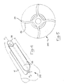
- the nail 10 shown in figures 1 and 2 which is suitable for insertion in a fractured elongate bone 12, such as for example a femur or a tibia, comprises a substantially straight stem 14 extending between a proximal end 16 and a distal end 18.
- the stem is preferably composed of a cylindrical tubular body.
- the stem 14 comprises at least a substantially longitudinal distribution 20 of expansion means for the nail fixation to the bone.
- the substantially longitudinal distribution 20 comprises at least an element 22 realised with a shape-memory material, a free end 24 of said at least one element 22 positioning outside the stem 14 to perform said fixation.
- Shape memory material means a material having a given initial starting shape and taking, under predetermined external conditions (for example a temperature rise and/or drop) or undergoing a predetermined activation condition, i.e. after a so-called “material instruction” step, a given new shape.
- Known shape-memory materials which are suitable for use in the present invention, are, for instance, certain nickel-titanium alloys.
- the invention is based on the following principle: subjecting an element realised in a shape memory material, having a predetermined initial shape at rest, to said so-called “material instruction” step (for example to a predetermined temperature variation), said element takes a shape being maintained as long as the "instruction” step effect persists; said shape, being different from the initial shape, can be called transient shape and it is temporary or unstable.
- the "instruction” step effect stops, the element leaves said transient shape and, coming back towards the initial shape, takes a working shape.
- said material can arrive at the initial shape or it can go further on the initial shape, arriving at a final shape. It is worth pointing out that the more this final shape is far from the initial shape, the more the available shape memory energy of the material is high.
- the invention has been reached as result of the intuition that an element realised in a shape memory material, in the passage from the transient shape towards the working shape, can create the fixing of the intramedullary nail in the bone.
- the substantially longitudinal distributions 20 are three and they are angularly equally spaced around the side surface of the cylindrical tubular body of the stem 14
- the element 22 made of a shape-memory material of each distribution 20 shapes in a substantially rectangular tongue 26, with the longest side being longitudinally developed with respect to the stem 14 and about as long as the stem 14.
- the tongue 26 is connected outside the stem 14 by a longest side thereof, while the opposite longest side is the free end 24 of said element 22.
- the tongues 26 are positioned in a substantially tangential way with respect to the cylindrical tubular body of the stem 14, the tongues 26 being all positioned with a same rotation direction, i.e. the free ends 24 of the tongues 26 being all for example arranged in an angular position preceding (once the clockwise direction is set) the angular position of the longest side connected to the stem 14.
- the tongue 26 In the initial shape the tongue 26 is bent towards the side surface of the stem 14, it abuts for example on the side surface of the stem 14, and according to the width thereof, it can partially abuts on the adjacent tongue 26 (i.e. the tongue being arranged in an angular position preceding the angular position of the tongue 26 being concerned, the clockwise direction being always set).
- the tongues 26 have connection arcs with the stem 14 being such as to reduce the stress concentration; meanwhile, these arcs have a limited extension, since it is worth allowing the deformation of most of each tongue 26.
- the stem 14, at one end, has a head 28 having a substantially cylindrical shape and an axis substantially coinciding with the stem 14 axis: said head 28 has traditional means for hooking the nail 10, during the insertion thereof in the bone 12, with a traditional external guide device.
- the nail 110 according to the invention is shown, having a similar structure to the structure of the nail 10 of figure 1, with an additional covering element 130 enveloping the tongues 26 of the stem 14.
- the covering element 130 shapes in a flat spiral spring which is preferably constrained to the free end 24 of a tongue 26.
- the flat spiral spring being longitudinally developed with respect to the stem 14, has a rest inner diameter being substantially equal to the cylindrical dimension of the tongues 26 in the initial position thereof.
- the inner diameter of the spiral spring is expanded according to the position taken by the free ends 24 of the three tongues 26.
- the spiral spring has outwardly a considerably rough surface.
- the nail 210 according to the invention is shown, wherein the substantially longitudinal distributions 20 are four and they are angularly equally spaced around the side surface of the cylindrical tubular body of the stem 14
- the element 22 made of a shape-memory material of each distribution 20 shapes in a substantially rectangular tongue 26, with the longest side being longitudinally developed with respect to the stem 14 and about as long as the stem 14.
- the tongue 26 is connected outside the stem 14 by a longest side thereof, while the opposite longest side is the free end 24 of said element 22.
- the tongues 26 are positioned in a substantially tangential way with respect to the cylindrical tubular body of the stem 14, the tongues 26 being all positioned with a same rotation direction, i.e. the free ends 24 of the tongues 26 being all for example arranged in an angular position preceding (once the clockwise direction is set) the angular position of the longest side connected to the stem 14.
- the tongues 26 are bent outside the stem 14: more precisely, the tongue concavity is the one deriving from the fact that the free end 24 of the tongue 26 is arranged in an angular position following (once the clockwise direction is set) the angular position of the respective tangent to the cylindrical tubular body of the stem 14.
- the tongue 26 In the initial shape the tongue 26 is bent towards the side surface of the stem 14, it abuts for example on the side surface of the stem 14, and according to the width thereof, it can partially abuts on the adjacent tongue 26 (i.e. the tongue being arranged in an angular position preceding the angular position of the tongue 26 being concerned, the clockwise direction being always set).
- the tongues 26 have connection arcs with the stem 14 being such as to reduce the stress concentration; meanwhile, these arcs have a limited extension, since it is worth allowing the deformation of most of each tongue 26.
- the stem 14, at one end, has a head 28 having a substantially cylindrical shape and an axis substantially coinciding with the stem 14 axis: said head 28 has traditional means for hooking the nail 10, during the insertion thereof in the bone 12, with a traditional external guide device.
- the nail 310 according to the invention is shown, wherein the elements 22 made of a shape-memory material of the substantially longitudinal distributions 20 shape in a plurality of corrugations 332 of a tubular structure 334 realised with a shape-memory material.
- the corrugations 332 are continuously distributed along the side surface of the tubular structure 334, which is internally constrained to the cylindrical tubular body of the stem 14.
- the tubular structure 334 is self load-bearing.
- the tubular structure 334 undergoes an instruction step of the shape-memory material wherein, starting from a tubular structure with a circular outer profile (final shape of the nail 310), a tubular structure with a more reduced outer dimension is obtained (initial shape of the nail 310), by forming successive corrugations 332.
- the free ends 24 of the corrugations 332 are practically the grooves of the corrugations 332, which, in the final shape of the nail 310, are positioned outside the initial dimension of the tubular structure 334, to perform the nail fixation to the bone.
- the outer diameter of the tubular structure 334 in the final shape can be of 20 mm, while the thickness of the tubular structure 334 can be of 0,4 mm.
- the nail 410 according to the invention is shown, wherein the element 22 made of a shape-memory material of the substantially longitudinal distribution 20 shapes in a covering element 430 enveloping the stem 14.
- the covering element 430 shapes in a flat-spiral-shaped bent plate.
- An end of said plate is connected to the stem 14 through traditional connection means, such as welding or mechanical joint, so to be substantially tangent to the cylindrical tubular body of the stem 14.
- the free end 24 of the shape-memory element 22 is positioned, with respect to the stem 14, far outside than in the initial shape of the nail 410.
- the plate flat spiral enlarges, i.e. it radially expands when passing from the initial shape to the final shape.
- the bent plate can also be split into pieces, to limit the risk of rotation of the nail 410 in the bone in the plate expansion step.
- the nail 510 according to the invention is shown, wherein the element 22 made of a shape-memory material of the substantially longitudinal distribution 20 shapes in a covering element 530 enveloping the stem 14.
- the covering element 530 shapes in a flat-spiral-shaped bent plate.
- An end of said plate is connected to the stem 14 through traditional connection means, such as welding or mechanical joint, so that the flat spiral strays in a substantially radial direction with respect to the stem 14 and it is preferably developed for about a turn and a half.
- the free end 24 of the shape-memory element 22 is positioned, with respect to the stem 14, far outside than in the initial shape of the nail 510.
- the plate flat spiral enlarges, i.e. it radially expands when passing from the initial shape to the final shape.
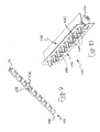
- the nail 610 according to the invention is shown, wherein the substantially longitudinal distributions 20 shape in two shaped plates 636 and 638, realised with a shape-memory material.
- the shaped plates 636 and 638 in the final shape, are substantially flat and they are substantially rectangle-shaped, with the longest side being developed with the axis of the stem 14 and about as long as the stem 14.
- each of said shaped plates 636 and 638 is connected to the stem 14, along an intermediate line between the rectangle longest sides of the respective plates 636 and 638, in a substantially tangential way to the stem 14, for example by welding.
- the intermediate connection lines are positioned substantially parallel to the axis of the stem 14, and they are for example offset on the outer surface of the stem 14 by about a right angle.
- these lacks 640 shape in rectangular slits, positioned in series in the direction of the longest side of the rectangle of the plate 636.
- these lacks 642 shape in rectangular slots, positioned in series in the direction of the longest side of the rectangle of the plate 638.
- the slots are realised starting from a longest side of the rectangle of the plate 638 and they thus define a series of teeth 644, being positioned in correspondence with the rectangular slits and having suitable dimensions for passing through these slits.
- the above description corresponds to the final shape of the two shaped plates 636 and 638 having thus globally four series of free ends 24 for the fixation and i.e. the two longest sides of the rectangle of the plate 636, the teeth 644 and the longest side of the rectangle of the plate 638 being opposite to the teeth 644.
- the two plates 636 and 638 are bent with the concavity towards the stem 14; in other words, they lie enveloped on the outer surface of the stem 14.
- the plates 636 and 638, intersecting with each other as above described have an outer dimension equal to a cylinder with a diameter of 19 mm.
- a ferrule 646 is preferably positioned at one end of the stem 14 to improve the insertion of the nail 610.
- This ferrule shapes in an ellipsoid portion, centrally drilled in correspondence with the axis of the stem 14.
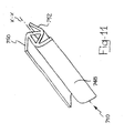
- the nail 710 according to the invention is shown, wherein the substantially longitudinal distributions 20 shape in three plates 748, 750 and 752, realised with a shape-memory material.
- the three plates 748, 750 and 752 are substantially flat and rectangular, with the longest side along the axis of the nail 710.
- connection occurs by joining a longest side of a plate to an intermediate and parallel line to the longest sides of the rectangle of the adjacent plate.
- an equilateral-triangle-shaped section exists, with each of the three sides extending on a same side with respect to the single side being considered.
- the plates 748, 750 and 752 are bent in correspondence with the respective intermediate lines of the mutual connection, so that, reasoning in the section terms, the extension of each side of the equilateral triangle is bent towards the side connected to the side being considered.
- the stem 14 is inserted in the three so-connected plates 748, 750 and 752 and it is constrained thereto.
- An application method of an intramedullary nail according to the present invention in said fractured elongate bone 12 comprises:
- the nail according to the invention is positioned in said elongate bone 12, in the initial shape thereof, the stem 14 playing a structural role.
- said at least one element 22 realised with a shape-memory material is operated: the free ends 24 of said at least one substantially longitudinal distribution 20 of expansion means tend to be positioned outside the stem 14 to realise an interference between said free ends 24 and the bone portion surrounding them. This interference practically causes a grip, solidly fixing the nail in the bone 12.
- the main advantage achieved by the intramedullary nail suitable for insertion in a fractured elongate bone, as well as by the application method of said nail in said fractured bone, according to the present invention, is the fact of unusually simplifying the fixation step of the intramedullary nail inserted in the fractured bone.
- the nail fixation is obtained simultaneously with the insertion thereof in the bone, since the shape-memory elements, cooled at first to take the initial shape, take in the bone their final shape, due to the heat released by the patient's body.
- Another advantage of the intramedullary nail according to the present invention is to prevent undesired nail torsions or rotations in the bone during the application step, due to the structural continuity of the described embodiments.
- a further advantage of the intramedullary nail according to the present invention is that the stem in the shape of a cylindrical tubular body allows an easy insertion in the bone by using a guide wire.
- the load applied on the medullary canal of the bone 12 by the three tongues 26 is advantageously distributed along the circumference of the stem 14.
- the shortest side of the rectangle of the tongues 26 can be very long, exploiting all the space of the stem 14 lying between one tongue and the other.
- the head 28 allows the shape-memory tongues 26 to be slightly below the insertion point of the nail 10.
- the spiral spring has outwardly a considerably rough surface to ensure a high friction between the spring and the bone 12 when in the fixation conditions of the nail 110.
- the heat 28 allows the shape-memory tongues 26 to be slightly below the insertion point of the nail 210.
Landscapes
- Health & Medical Sciences (AREA)
- Orthopedic Medicine & Surgery (AREA)
- Surgery (AREA)
- Life Sciences & Earth Sciences (AREA)
- Heart & Thoracic Surgery (AREA)
- Nuclear Medicine, Radiotherapy & Molecular Imaging (AREA)
- Engineering & Computer Science (AREA)
- Biomedical Technology (AREA)
- Neurology (AREA)
- Medical Informatics (AREA)
- Molecular Biology (AREA)
- Animal Behavior & Ethology (AREA)
- General Health & Medical Sciences (AREA)
- Public Health (AREA)
- Veterinary Medicine (AREA)
- Surgical Instruments (AREA)
Priority Applications (2)
| Application Number | Priority Date | Filing Date | Title |
|---|---|---|---|
| EP04007788A EP1582162A1 (de) | 2004-03-31 | 2004-03-31 | Marknagel mit einem Fixationsmittel aus einem Material mit Formgedächtniseffekt |
| PCT/EP2005/003392 WO2005094705A2 (en) | 2004-03-31 | 2005-03-31 | Shape memory alloy comprising intramedullary nail provided with expansion fixing means |
Applications Claiming Priority (1)
| Application Number | Priority Date | Filing Date | Title |
|---|---|---|---|
| EP04007788A EP1582162A1 (de) | 2004-03-31 | 2004-03-31 | Marknagel mit einem Fixationsmittel aus einem Material mit Formgedächtniseffekt |
Publications (1)
| Publication Number | Publication Date |
|---|---|
| EP1582162A1 true EP1582162A1 (de) | 2005-10-05 |
Family
ID=34878222
Family Applications (1)
| Application Number | Title | Priority Date | Filing Date |
|---|---|---|---|
| EP04007788A Withdrawn EP1582162A1 (de) | 2004-03-31 | 2004-03-31 | Marknagel mit einem Fixationsmittel aus einem Material mit Formgedächtniseffekt |
Country Status (1)
| Country | Link |
|---|---|
| EP (1) | EP1582162A1 (de) |
Cited By (7)
| Publication number | Priority date | Publication date | Assignee | Title |
|---|---|---|---|---|
| EP1923012A1 (de) * | 2006-11-16 | 2008-05-21 | Newdeal | Implantat für die interphalangäre Arthrodese, entsprechender chirurgischer Teilesatz und Herstellungsverfahren |
| US8128627B2 (en) | 2007-03-22 | 2012-03-06 | Sonoma Orthopedic Products, Inc. | Segmented intramedullary system and apparatus |
| US8287538B2 (en) | 2008-01-14 | 2012-10-16 | Conventus Orthopaedics, Inc. | Apparatus and methods for fracture repair |
| US8906022B2 (en) | 2010-03-08 | 2014-12-09 | Conventus Orthopaedics, Inc. | Apparatus and methods for securing a bone implant |
| US8961518B2 (en) | 2010-01-20 | 2015-02-24 | Conventus Orthopaedics, Inc. | Apparatus and methods for bone access and cavity preparation |
| US9730739B2 (en) | 2010-01-15 | 2017-08-15 | Conventus Orthopaedics, Inc. | Rotary-rigid orthopaedic rod |
| US10022132B2 (en) | 2013-12-12 | 2018-07-17 | Conventus Orthopaedics, Inc. | Tissue displacement tools and methods |
Citations (5)
| Publication number | Priority date | Publication date | Assignee | Title |
|---|---|---|---|---|
| GB2114005A (en) * | 1982-01-15 | 1983-08-17 | Krupp Gmbh | Marrow nail |
| EP0772420A1 (de) | 1994-07-28 | 1997-05-14 | ORTHOFIX S.r.l. | Mechanische vorrichtung zum ausrichten von knochenschrauben,die in einem marknagel einzulassen sind |
| EP0882431A1 (de) * | 1997-06-05 | 1998-12-09 | Claudio Di Bartolomei | Vorrichtung zur elastischen intramedullären Synthese von Knochenfracturen |
| US6127597A (en) * | 1997-03-07 | 2000-10-03 | Discotech N.V. | Systems for percutaneous bone and spinal stabilization, fixation and repair |
| US20030130660A1 (en) * | 1998-10-26 | 2003-07-10 | Expanding Orthopedics, Inc. | Expandable orthopedic device |
-
2004
- 2004-03-31 EP EP04007788A patent/EP1582162A1/de not_active Withdrawn
Patent Citations (5)
| Publication number | Priority date | Publication date | Assignee | Title |
|---|---|---|---|---|
| GB2114005A (en) * | 1982-01-15 | 1983-08-17 | Krupp Gmbh | Marrow nail |
| EP0772420A1 (de) | 1994-07-28 | 1997-05-14 | ORTHOFIX S.r.l. | Mechanische vorrichtung zum ausrichten von knochenschrauben,die in einem marknagel einzulassen sind |
| US6127597A (en) * | 1997-03-07 | 2000-10-03 | Discotech N.V. | Systems for percutaneous bone and spinal stabilization, fixation and repair |
| EP0882431A1 (de) * | 1997-06-05 | 1998-12-09 | Claudio Di Bartolomei | Vorrichtung zur elastischen intramedullären Synthese von Knochenfracturen |
| US20030130660A1 (en) * | 1998-10-26 | 2003-07-10 | Expanding Orthopedics, Inc. | Expandable orthopedic device |
Cited By (17)
| Publication number | Priority date | Publication date | Assignee | Title |
|---|---|---|---|---|
| FR2908626A1 (fr) * | 2006-11-16 | 2008-05-23 | Newdeal Soc Par Actions Simpli | Implant d'arthrodese inter-phalangienne,kit chirurgical et procede de fabrication correspondants |
| EP1923012A1 (de) * | 2006-11-16 | 2008-05-21 | Newdeal | Implantat für die interphalangäre Arthrodese, entsprechender chirurgischer Teilesatz und Herstellungsverfahren |
| US8496658B2 (en) | 2007-03-22 | 2013-07-30 | Sonoma Orthopedic Products, Inc. | Segmented intramedullary structure |
| US8128627B2 (en) | 2007-03-22 | 2012-03-06 | Sonoma Orthopedic Products, Inc. | Segmented intramedullary system and apparatus |
| US8430879B2 (en) | 2007-03-22 | 2013-04-30 | Sonoma Orthopedic Products, Inc. | Segmented intramedullary structure |
| US9517093B2 (en) | 2008-01-14 | 2016-12-13 | Conventus Orthopaedics, Inc. | Apparatus and methods for fracture repair |
| US8287538B2 (en) | 2008-01-14 | 2012-10-16 | Conventus Orthopaedics, Inc. | Apparatus and methods for fracture repair |
| US9788870B2 (en) | 2008-01-14 | 2017-10-17 | Conventus Orthopaedics, Inc. | Apparatus and methods for fracture repair |
| US10603087B2 (en) | 2008-01-14 | 2020-03-31 | Conventus Orthopaedics, Inc. | Apparatus and methods for fracture repair |
| US11399878B2 (en) | 2008-01-14 | 2022-08-02 | Conventus Orthopaedics, Inc. | Apparatus and methods for fracture repair |
| US9730739B2 (en) | 2010-01-15 | 2017-08-15 | Conventus Orthopaedics, Inc. | Rotary-rigid orthopaedic rod |
| US8961518B2 (en) | 2010-01-20 | 2015-02-24 | Conventus Orthopaedics, Inc. | Apparatus and methods for bone access and cavity preparation |
| US9848889B2 (en) | 2010-01-20 | 2017-12-26 | Conventus Orthopaedics, Inc. | Apparatus and methods for bone access and cavity preparation |
| US8906022B2 (en) | 2010-03-08 | 2014-12-09 | Conventus Orthopaedics, Inc. | Apparatus and methods for securing a bone implant |
| US9993277B2 (en) | 2010-03-08 | 2018-06-12 | Conventus Orthopaedics, Inc. | Apparatus and methods for securing a bone implant |
| US10022132B2 (en) | 2013-12-12 | 2018-07-17 | Conventus Orthopaedics, Inc. | Tissue displacement tools and methods |
| US10076342B2 (en) | 2013-12-12 | 2018-09-18 | Conventus Orthopaedics, Inc. | Tissue displacement tools and methods |
Similar Documents
| Publication | Publication Date | Title |
|---|---|---|
| EP1815813B1 (de) | Intramedullärer Nagel mit Expansionsmitteln zur Fixierung im Knochen | |
| US20250177023A1 (en) | Compact orthopedic anti-rotation device | |
| EP1582159A1 (de) | Intramedullärer Nagel mit Expansionsmitteln zur Fixierung im Knochen | |
| US8048134B2 (en) | Active compression to facilitate healing of bones | |
| KR101215012B1 (ko) | 뼈 고정 요소 | |
| EP1582163A1 (de) | Marknagel mit einem spiralförmigen Element aus Formgedächtnismaterial | |
| EP3322362B1 (de) | Knochenplatten mit dynamischen elementen | |
| US20140276830A1 (en) | Bone staples and methods of use therefor and manufacturing thereof | |
| US20100023010A1 (en) | Fracture fixation device, tools and methods | |
| WO2005094705A2 (en) | Shape memory alloy comprising intramedullary nail provided with expansion fixing means | |
| KR20140072826A (ko) | 동적 뼈 고정기 및 동적 뼈 고정기의 제조 방법 | |
| WO2009150691A1 (en) | Intermarrow nail to be inserted into a fractured long bone | |
| JP2019513469A (ja) | 関節内で圧縮を生成して加えるための関節固定装置 | |
| FR2884406A1 (fr) | Dispositif d'osteosynthese intramedullaire de deux parties d'os, notamment de la main et/ou du pied | |
| EP1582162A1 (de) | Marknagel mit einem Fixationsmittel aus einem Material mit Formgedächtniseffekt | |
| EP1582161A1 (de) | Intramedullärer Nagel mit expandierenden, durch ein oder mehrere Antriebselemente betätigten Fixierungsmitteln | |
| EP1582164A1 (de) | Marknagel, der eine Stamm und Formgedächtnislegierungselemente enthält | |
| US12268426B2 (en) | Orthopedic torsion generated compression implants and methods for using same | |
| EP1582160A1 (de) | Intramedullärer Nagel mit Formgedächtniselementen | |
| WO2012158208A2 (en) | Implant and fastener fixation devices and delivery instrumentation | |
| US20250204909A1 (en) | Orthopedic torsion generated compression implants and methods for using same | |
| WO2025029749A2 (en) | Compression closure devices and methods of using the same | |
| HK1099911B (en) | Intramedullary nail comprising elements of shape-memory material | |
| HK1255808B (en) | Bone plates with dynamic elements |
Legal Events
| Date | Code | Title | Description |
|---|---|---|---|
| PUAI | Public reference made under article 153(3) epc to a published international application that has entered the european phase |
Free format text: ORIGINAL CODE: 0009012 |
|
| AK | Designated contracting states |
Kind code of ref document: A1 Designated state(s): AT BE BG CH CY CZ DE DK EE ES FI FR GB GR HU IE IT LI LU MC NL PL PT RO SE SI SK TR |
|
| AX | Request for extension of the european patent |
Extension state: AL LT LV MK |
|
| AKX | Designation fees paid | ||
| REG | Reference to a national code |
Ref country code: DE Ref legal event code: 8566 |
|
| STAA | Information on the status of an ep patent application or granted ep patent |
Free format text: STATUS: THE APPLICATION IS DEEMED TO BE WITHDRAWN |
|
| 18D | Application deemed to be withdrawn |
Effective date: 20060406 |