EP1581713B1 - A hinge and use thereof - Google Patents
A hinge and use thereof Download PDFInfo
- Publication number
- EP1581713B1 EP1581713B1 EP03767486A EP03767486A EP1581713B1 EP 1581713 B1 EP1581713 B1 EP 1581713B1 EP 03767486 A EP03767486 A EP 03767486A EP 03767486 A EP03767486 A EP 03767486A EP 1581713 B1 EP1581713 B1 EP 1581713B1
- Authority
- EP
- European Patent Office
- Prior art keywords
- bracket
- shaped part
- pin
- hinge
- section
- Prior art date
- Legal status (The legal status is an assumption and is not a legal conclusion. Google has not performed a legal analysis and makes no representation as to the accuracy of the status listed.)
- Expired - Lifetime
Links
- 230000004888 barrier function Effects 0.000 claims abstract description 8
- 238000006073 displacement reaction Methods 0.000 claims description 4
- 239000000463 material Substances 0.000 claims description 3
- 229920003023 plastic Polymers 0.000 claims description 3
- 239000004033 plastic Substances 0.000 claims description 3
- 238000004519 manufacturing process Methods 0.000 description 2
- 238000010276 construction Methods 0.000 description 1
Images
Classifications
-
- E—FIXED CONSTRUCTIONS
- E05—LOCKS; KEYS; WINDOW OR DOOR FITTINGS; SAFES
- E05D—HINGES OR SUSPENSION DEVICES FOR DOORS, WINDOWS OR WINGS
- E05D3/00—Hinges with pins
- E05D3/02—Hinges with pins with one pin
-
- E—FIXED CONSTRUCTIONS
- E05—LOCKS; KEYS; WINDOW OR DOOR FITTINGS; SAFES
- E05D—HINGES OR SUSPENSION DEVICES FOR DOORS, WINDOWS OR WINGS
- E05D11/00—Additional features or accessories of hinges
- E05D11/10—Devices for preventing movement between relatively-movable hinge parts
- E05D11/1007—Devices for preventing movement between relatively-movable hinge parts with positive locking
-
- E—FIXED CONSTRUCTIONS
- E06—DOORS, WINDOWS, SHUTTERS, OR ROLLER BLINDS IN GENERAL; LADDERS
- E06B—FIXED OR MOVABLE CLOSURES FOR OPENINGS IN BUILDINGS, VEHICLES, FENCES OR LIKE ENCLOSURES IN GENERAL, e.g. DOORS, WINDOWS, BLINDS, GATES
- E06B9/00—Screening or protective devices for wall or similar openings, with or without operating or securing mechanisms; Closures of similar construction
- E06B9/02—Shutters, movable grilles, or other safety closing devices, e.g. against burglary
- E06B9/04—Shutters, movable grilles, or other safety closing devices, e.g. against burglary of wing type, e.g. revolving or sliding
-
- E—FIXED CONSTRUCTIONS
- E05—LOCKS; KEYS; WINDOW OR DOOR FITTINGS; SAFES
- E05D—HINGES OR SUSPENSION DEVICES FOR DOORS, WINDOWS OR WINGS
- E05D11/00—Additional features or accessories of hinges
-
- E—FIXED CONSTRUCTIONS
- E05—LOCKS; KEYS; WINDOW OR DOOR FITTINGS; SAFES
- E05D—HINGES OR SUSPENSION DEVICES FOR DOORS, WINDOWS OR WINGS
- E05D15/00—Suspension arrangements for wings
- E05D15/56—Suspension arrangements for wings with successive different movements
- E05D15/58—Suspension arrangements for wings with successive different movements with both swinging and sliding movements
- E05D15/581—Suspension arrangements for wings with successive different movements with both swinging and sliding movements the swinging axis laying in the sliding direction
-
- E—FIXED CONSTRUCTIONS
- E05—LOCKS; KEYS; WINDOW OR DOOR FITTINGS; SAFES
- E05D—HINGES OR SUSPENSION DEVICES FOR DOORS, WINDOWS OR WINGS
- E05D3/00—Hinges with pins
- E05D3/02—Hinges with pins with one pin
- E05D3/022—Hinges with pins with one pin allowing an additional lateral movement, e.g. for sealing
-
- E—FIXED CONSTRUCTIONS
- E05—LOCKS; KEYS; WINDOW OR DOOR FITTINGS; SAFES
- E05Y—INDEXING SCHEME ASSOCIATED WITH SUBCLASSES E05D AND E05F, RELATING TO CONSTRUCTION ELEMENTS, ELECTRIC CONTROL, POWER SUPPLY, POWER SIGNAL OR TRANSMISSION, USER INTERFACES, MOUNTING OR COUPLING, DETAILS, ACCESSORIES, AUXILIARY OPERATIONS NOT OTHERWISE PROVIDED FOR, APPLICATION THEREOF
- E05Y2800/00—Details, accessories and auxiliary operations not otherwise provided for
- E05Y2800/40—Physical or chemical protection
- E05Y2800/424—Physical or chemical protection against unintended use, e.g. protection against vandalism or sabotage
- E05Y2800/426—Physical or chemical protection against unintended use, e.g. protection against vandalism or sabotage against unauthorised use, e.g. keys
-
- E—FIXED CONSTRUCTIONS
- E05—LOCKS; KEYS; WINDOW OR DOOR FITTINGS; SAFES
- E05Y—INDEXING SCHEME ASSOCIATED WITH SUBCLASSES E05D AND E05F, RELATING TO CONSTRUCTION ELEMENTS, ELECTRIC CONTROL, POWER SUPPLY, POWER SIGNAL OR TRANSMISSION, USER INTERFACES, MOUNTING OR COUPLING, DETAILS, ACCESSORIES, AUXILIARY OPERATIONS NOT OTHERWISE PROVIDED FOR, APPLICATION THEREOF
- E05Y2900/00—Application of doors, windows, wings or fittings thereof
- E05Y2900/40—Application of doors, windows, wings or fittings thereof for gates
-
- E—FIXED CONSTRUCTIONS
- E06—DOORS, WINDOWS, SHUTTERS, OR ROLLER BLINDS IN GENERAL; LADDERS
- E06B—FIXED OR MOVABLE CLOSURES FOR OPENINGS IN BUILDINGS, VEHICLES, FENCES OR LIKE ENCLOSURES IN GENERAL, e.g. DOORS, WINDOWS, BLINDS, GATES
- E06B9/00—Screening or protective devices for wall or similar openings, with or without operating or securing mechanisms; Closures of similar construction
- E06B2009/002—Safety guards or gates
Definitions
- the invention relates to a hinge according to the preamble of claim 1 and consists of first and second bracket parts, wherein the first bracket part is formed with a pin, while the second bracket part is formed with a hole to receive the pin, where the hole is made in two sections, one section having a larger diameter than the other section, and where a shoulder is provided on a portion of the surface of the pin, and where the section of the hole of the largest diameter is longer than the section of the smallest diameter, and in that the shoulder is provided near the free end of the pin, said shoulder is dimensioned to pass the section of the smallest diameter by pressure.
- hinges are used in many connections, such as in the mounting of doors of the conventional type.
- hinges are used for doors in child safety barriers, playpens and like.
- the hinges are frequently made of plastics, and instead of the pin a screw is used for the joining of the two bracket parts of the hinge. Since doors for child safety barriers are to be protected against unintentional opening, they are constructed in some cases such that a vertical lifting movement of the door must be carried out before it can be opened, which requires that the hinge of the door is prepared for this.
- This door structure has a hinge arranged such as to allow the door to be opened or closed after a vertical movement of the door has been carried out.
- the hinge is composed of several parts, including a bolt, in a rather complicated manner.
- a hinge of the kind defined in the introductory part of claim 1 is known from US-A-5,127,132 . This hinge construction is not intended to be used such that the two bracket parts of the hinge can be moved vertically relative to each other.
- an object of the invention is to provide a hinge which is relatively inexpensive to manufacture, where the two bracket parts of the hinge can be moved vertically relative to each other.
- the object of the invention is achieved by a hinge defined in claim 1.
- the locking part on the first bracket part is formed by a box-shaped part which is terminated on a portion of its lower side by a plate-shaped part having larger horizontal dimensions than the box-shaped part, and the plate-shaped part has a free surface which is flush with one free end of the box-shaped part
- the locking part on the second bracket part is formed by a box-shaped part, which is terminated at its one end by another block-shaped part having larger horizontal dimensions than the box-shaped part, the block-shaped part has a free surface, said free surface of the plate-shaped part adjoining the free surface of the blocked shaped part when the locking parts are locked together.
- brackets it is possible to move the brackets relative to each other, without the risk of separating the bracket parts from each other.
- bracket parts are made of the same material, e.g. hard plastics as stated in claim 4, it is ensured that the manufacturing costs of the brackets may be kept reasonably low.
- the invention also relates to use of the hinge.
- the numeral 1 designates a first bracket part
- 2 designates a second bracket part which has a tooth engagement capable of cooperating with another tooth engagement (not shown), and the two tooth engagements may be positioned relative to each other by vertical displacement, e.g. as explained in connection with the safety barrier described in WO 00/11301 .
- the first bracket part 1, cf. fig. 3 has a pin 4 adapted to engage a hole 7 on the second bracket part 2.
- the pin 4 moreover has a shoulder 5, as will be seen in fig. 3.
- the hole 7 is formed with two sections (not shown), where one section has a larger diameter than the other section.
- the section of the largest diameter is disposed at the end designated 8 in fig. 2.
- the section of the smallest diameter has a diameter which allows the shoulder 5 on the pin 4 to pass only when it is subjected to a force, while the hole of the largest diameter allows the pin 4 with the shoulder 5 to move freely.
- the pin 4 with the shoulder 5 on the first bracket part 1 is pressed into the hole 7 in the section of the smallest diameter.
- the two bracket parts are hereby locked together, but since the shoulder 5 is pressed into the section of the largest diameter, the two bracket parts may be moved relative to each other by rotation. If, moreover, the section of the smallest diameter has a length shorter than the pin 5, the two bracket parts of the hinge may be displaced mutually in the direction of the pin in addition to being rotated relative to each other, as the pin with the shoulder when displaced just slightly into the hole reaches the section of the largest diameter.
- fig. 4 shows a hinge which is basically constructed like the hinge of figs. 1 - 3, but now provided with a locking function, as will be explained below.
- the numeral 9 designates a first bracket part, while 10 designates a second bracket part.
- the first bracket part 9 is formed by a box-shaped part 18 which, on a portion of its lower side, is formed with a plate-shaped part 13 having horizontal dimensions which are larger than the box-shaped part.
- the free end 20 of the plate 13 is rectangular.
- the plate-shaped part 13 constitutes a first part of a locking mechanism which cooperates with a locking mechanism on the second bracket part 10.
- the second bracket part 10 is formed by a box-shaped part 19 which, on a portion of its lower side, is formed with a block-shaped part 16 which also has horizontal dimensions larger than the box-shaped part 19.
- the free end of the block-shaped part is formed as a square with a free surface 17.
- the second bracket part, 10 is formed with two symmetrical collars 15 whose free ends are terminated a distance downwards by the free surface 17 so as to create a gap between the collars and the plate-shaped part 13 on the first bracket part 9.
- Fig. 5 shows the hinge in a locked state, where the locking function is provided by the plate member 13, with its free end 20 adjoining the free surface 17 of the block-shaped part 16.
- the hinge described may advantageously be used in connection with the safety barrier described in WO 97/40253 , in which the safety barrier has to be lifted before it may be rotated and thereby opened and closed, respectively.
Landscapes
- Engineering & Computer Science (AREA)
- Mechanical Engineering (AREA)
- Structural Engineering (AREA)
- Architecture (AREA)
- Civil Engineering (AREA)
- Hinges (AREA)
- Hinge Accessories (AREA)
- Pivots And Pivotal Connections (AREA)
- Respiratory Apparatuses And Protective Means (AREA)
Abstract
Description
- The invention relates to a hinge according to the preamble of claim 1 and consists of first and second bracket parts, wherein the first bracket part is formed with a pin, while the second bracket part is formed with a hole to receive the pin, where the hole is made in two sections, one section having a larger diameter than the other section, and where a shoulder is provided on a portion of the surface of the pin, and where the section of the hole of the largest diameter is longer than the section of the smallest diameter, and in that the shoulder is provided near the free end of the pin, said shoulder is dimensioned to pass the section of the smallest diameter by pressure.
- Such hinges are used in many connections, such as in the mounting of doors of the conventional type. In addition, hinges are used for doors in child safety barriers, playpens and like. In connection with the last-mentioned use, the hinges are frequently made of plastics, and instead of the pin a screw is used for the joining of the two bracket parts of the hinge. Since doors for child safety barriers are to be protected against unintentional opening, they are constructed in some cases such that a vertical lifting movement of the door must be carried out before it can be opened, which requires that the hinge of the door is prepared for this.
- An example of such a door structure is known from
WO 97/40253 - A hinge of the kind defined in the introductory part of claim 1 is known from
US-A-5,127,132 . This hinge construction is not intended to be used such that the two bracket parts of the hinge can be moved vertically relative to each other. - Accordingly, an object of the invention is to provide a hinge which is relatively inexpensive to manufacture, where the two bracket parts of the hinge can be moved vertically relative to each other.
- The object of the invention is achieved by a hinge defined in claim 1. The locking part on the first bracket part is formed by a box-shaped part which is terminated on a portion of its lower side by a plate-shaped part having larger horizontal dimensions than the box-shaped part, and the plate-shaped part has a free surface which is flush with one free end of the box-shaped part, the locking part on the second bracket part is formed by a box-shaped part, which is terminated at its one end by another block-shaped part having larger horizontal dimensions than the box-shaped part, the block-shaped part has a free surface, said free surface of the plate-shaped part adjoining the free surface of the blocked shaped part when the locking parts are locked together.
- Further, it is possible to move the brackets relative to each other, without the risk of separating the bracket parts from each other.
- Expedient as stated in
claim 2, is the second bracket part formed with symmetrical collars whose free ends and the plate shaped part create a gab. - When, as stated in
claim 3, the bracket parts are made of the same material, e.g. hard plastics as stated inclaim 4, it is ensured that the manufacturing costs of the brackets may be kept reasonably low. - As mentioned, the invention also relates to use of the hinge.
- This use is defined in
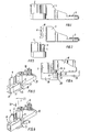
claim 5. - The invention will now be explained more fully with reference to the drawing, in which
- fig. 1
- shows a hinge consisting of first and second bracket parts,
- fig. 2
- shows the second bracket part of fig. 1,
- fig. 3
- shows the first bracket part of fig. 1,
- fig. 4
- shows a hinge according to the invention where the bracket parts are displaced relative to each other,
- fig. 5
- shows the hinge of fig. 4, seen obliquely from the side with the bracket parts in a locked state, while
- fig. 6
- shows the hinge of fig. 5 in a non-locked state.
- In figures 1 to 3, the numeral 1 designates a first bracket part, while 2 designates a second bracket part which has a tooth engagement capable of cooperating with another tooth engagement (not shown), and the two tooth engagements may be positioned relative to each other by vertical displacement, e.g. as explained in connection with the safety barrier described in
WO 00/11301 pin 4 adapted to engage ahole 7 on thesecond bracket part 2. Thepin 4 moreover has ashoulder 5, as will be seen in fig. 3. - The
hole 7 is formed with two sections (not shown), where one section has a larger diameter than the other section. The section of the largest diameter is disposed at the end designated 8 in fig. 2. The section of the smallest diameter has a diameter which allows theshoulder 5 on thepin 4 to pass only when it is subjected to a force, while the hole of the largest diameter allows thepin 4 with theshoulder 5 to move freely. - The function of the hinge will be explained now.
- When the first 1 and the second 2 bracket parts are assembled, the
pin 4 with theshoulder 5 on the first bracket part 1 is pressed into thehole 7 in the section of the smallest diameter. The two bracket parts are hereby locked together, but since theshoulder 5 is pressed into the section of the largest diameter, the two bracket parts may be moved relative to each other by rotation. If, moreover, the section of the smallest diameter has a length shorter than thepin 5, the two bracket parts of the hinge may be displaced mutually in the direction of the pin in addition to being rotated relative to each other, as the pin with the shoulder when displaced just slightly into the hole reaches the section of the largest diameter. - Such a displacement of the bracket parts relative to each other is shown in fig. 4, which shows a hinge which is basically constructed like the hinge of figs. 1 - 3, but now provided with a locking function, as will be explained below.
- In figures 4 - 6, the
numeral 9 designates a first bracket part, while 10 designates a second bracket part. - The
first bracket part 9 is formed by a box-shaped part 18 which, on a portion of its lower side, is formed with a plate-shaped part 13 having horizontal dimensions which are larger than the box-shaped part. Thefree end 20 of theplate 13 is rectangular. The plate-shaped part 13 constitutes a first part of a locking mechanism which cooperates with a locking mechanism on thesecond bracket part 10. - As will be seen in figs. 5 and 6, also the
second bracket part 10 is formed by a box-shaped part 19 which, on a portion of its lower side, is formed with a block-shaped part 16 which also has horizontal dimensions larger than the box-shaped part 19. The free end of the block-shaped part is formed as a square with afree surface 17. Finally, the second bracket part, 10 is formed with twosymmetrical collars 15 whose free ends are terminated a distance downwards by thefree surface 17 so as to create a gap between the collars and the plate-shaped part 13 on thefirst bracket part 9. - It will now be explained how the hinge of figs. 4 - 6 works:
- Fig. 5 shows the hinge in a locked state, where the locking function is provided by the
plate member 13, with itsfree end 20 adjoining thefree surface 17 of the block-shaped part 16. - Vertical displacement of the
second bracket part 10 causes the block-shaped part 16 to be displaced relative to the plate-shaped part 13, which means that the bracket parts may rotate relative to each other, as indicated by thearrow 22. - In the rotation, the
free surface 15 of one of the collars will slide on the upper surface of the box-shaped part 18, thereby providing stable fixing of the parts relative to each other. - The hinge described may advantageously be used in connection with the safety barrier described in
WO 97/40253
Claims (5)
- A hinge consisting of first (1, 9) and second (2, 10) bracket parts, wherein the first bracket part is formed with a pin (4), while the second bracket part is formed with a hole (7) to receive the pin, where the hole (7) is made in two sections, one section having a larger diameter than the other section, and where a shoulder (5) is provided on a portion of the surface of the pin (4), and where the section of the hole of the largest diameter is longer than the section of the smallest diameter, and in that the shoulder (5) is provided near the free end of the pin (4), said shoulder is dimensioned to pass the section of the smallest diameter by pressure, characterized in that the two bracket parts (1,9;2,10) may be displaced mutually in the direction of the pin (4) in addition to being rotated relative to each other, said first bracket part, (9) is formed with a locking part (13, 18, 20) which cooperates with a locking part (16, 17, 19) on the second bracket part (10), the locking part (13,18, 20) on the first bracket part (9) is formed by a first box-shaped part (18) which is terminated on a portion of its lower side by a plate-shaped part (13) having larger horizontal dimensions than the first box-shaped part (18), and that the plate-shaped part (13) has a free surface (20) which is flush with one free end of the first box-shaped (18) part, and that the locking part on the second bracket part (10) is formed by a second box-shaped part (19), which is terminated at its one end by another block-shaped part (16) having larger horizontal dimensions than the second box-shaped part (19), and that the second block-shaped part has a free surface (17), said free surface (20) of the plate shaped part (13) adjoining the free surface (17) of the blocked shaped part (16) when the locking parts are locked together, and unlocked by the said mutual displacement of the two bracket parts (1, 9; 2, 10) in the direction of the pin (4) allowing their rotation.
- A hinge according to claim 1, characterized in that the second bracket part (10) is formed with two symmetrical collars (15), whose free ends and the plate shaped part (13) create a gap.
- A hinge according to claims 1 - 2, characterized in that the bracket parts are made of the same material.
- A hinge according to claim 3, characterized in that the material is hard plastics.
- Use of a hinge according to claims 1 - 4 for a child safety barrier.
Applications Claiming Priority (3)
| Application Number | Priority Date | Filing Date | Title |
|---|---|---|---|
| DK200200414U DK200200414U4 (en) | 2002-12-30 | 2002-12-30 | Hinge and use of the same |
| DK200200414 | 2002-12-30 | ||
| PCT/DK2003/000928 WO2004059113A2 (en) | 2002-12-30 | 2003-12-22 | A hinge and use thereof |
Publications (2)
| Publication Number | Publication Date |
|---|---|
| EP1581713A2 EP1581713A2 (en) | 2005-10-05 |
| EP1581713B1 true EP1581713B1 (en) | 2007-10-24 |
Family
ID=8161230
Family Applications (1)
| Application Number | Title | Priority Date | Filing Date |
|---|---|---|---|
| EP03767486A Expired - Lifetime EP1581713B1 (en) | 2002-12-30 | 2003-12-22 | A hinge and use thereof |
Country Status (8)
| Country | Link |
|---|---|
| US (1) | US7281300B2 (en) |
| EP (1) | EP1581713B1 (en) |
| AT (1) | ATE376613T1 (en) |
| AU (1) | AU2003291970B2 (en) |
| DE (1) | DE60317104T2 (en) |
| DK (2) | DK200200414U4 (en) |
| ES (1) | ES2295652T3 (en) |
| WO (1) | WO2004059113A2 (en) |
Families Citing this family (6)
| Publication number | Priority date | Publication date | Assignee | Title |
|---|---|---|---|---|
| US7634837B2 (en) * | 2005-12-23 | 2009-12-22 | Middle Atlantic Products, Inc. | Lift-off hinge |
| DK177606B1 (en) * | 2011-11-28 | 2013-11-25 | Baby Dan As | A child safety barrier |
| US8458857B1 (en) | 2012-01-26 | 2013-06-11 | ADCO Industries—Technologies, L.P. | Blocking closure of a passageway |
| US9752350B2 (en) | 2014-12-12 | 2017-09-05 | Raymond E Davis | Hand and finger protector for use with doors |
| US9328546B1 (en) | 2015-02-21 | 2016-05-03 | Raymond E Davis | Hand and finger protector for use with doors |
| US9181749B1 (en) | 2015-03-05 | 2015-11-10 | Raymond E Davis | Deformable hinge gap blocker for the protection of hands and fingers |
Citations (2)
| Publication number | Priority date | Publication date | Assignee | Title |
|---|---|---|---|---|
| GB2115477A (en) * | 1982-02-16 | 1983-09-07 | John Shepherd | Hinges |
| DE8812589U1 (en) * | 1988-10-06 | 1988-12-01 | Knuerr-Mechanik Fuer Die Elektronik Ag, 8000 Muenchen | Case hinge |
Family Cites Families (22)
| Publication number | Priority date | Publication date | Assignee | Title |
|---|---|---|---|---|
| US1294044A (en) * | 1917-04-27 | 1919-02-11 | Martin C Buckwalter | Shutter-hinge. |
| FR2538838A2 (en) | 1980-07-24 | 1984-07-06 | Fima | Adjustable pin of new type for doors and windows |
| FR2570429B1 (en) | 1984-09-19 | 1986-12-05 | Plastic Omnium Cie | INVIOLABLE HINGE DEVICE, PARTICULARLY FOR THE ARTICULATED MOUNTING OF A COVER ON A ROLLING TRAY TANK |
| ATE37927T1 (en) | 1985-04-01 | 1988-10-15 | Alfred Locher | BRACKET FOR ATTACHING A LEAF TO AN RELATED FRAME. |
| US4847950A (en) * | 1986-08-01 | 1989-07-18 | Von Duprin, Inc. | Self retained axle pin assembly for shear application |
| DE3883978D1 (en) * | 1988-09-22 | 1993-10-14 | Dieter Ramsauer | Hinge pin. |
| DE3834053A1 (en) * | 1988-10-06 | 1990-04-12 | Knuerr Mechanik Ag | CASE HINGE |
| US4937916A (en) * | 1988-12-07 | 1990-07-03 | Kawneer Company, Inc. | Offset door pivot |
| US4987639A (en) * | 1989-01-05 | 1991-01-29 | Ropak Corporation | Frangible fastening construction for handles and method of fastening |
| JPH0826721B2 (en) * | 1989-03-29 | 1996-03-21 | ワイケイケイ株式会社 | Door hinge mounting device |
| US5127132A (en) * | 1991-07-22 | 1992-07-07 | James Karlin | Hinge made from identical hinge plates |
| FR2681092B1 (en) * | 1991-09-05 | 1995-12-01 | Etude Dev Indl Technol | HINGE-TYPE DOOR STOP DEVICE, PARTICULARLY FOR A VEHICLE DOOR. |
| GB2259946B (en) * | 1991-09-20 | 1994-09-14 | Malcoe Precision Fabrications | Hinge |
| DE9214963U1 (en) * | 1992-06-10 | 1992-12-24 | Knürr-Mechanik für die Elektronik AG, 8000 München | hinge |
| JPH06146696A (en) * | 1992-10-30 | 1994-05-27 | Sanyo Electric Co Ltd | Hinge assembly method |
| US5396732A (en) * | 1993-03-29 | 1995-03-14 | Andersen; Finn | Safety barrier |
| US5564163A (en) * | 1994-11-08 | 1996-10-15 | Cema Technologies, Inc. | Lockable hinge assembly |
| WO1997040253A1 (en) * | 1996-04-24 | 1997-10-30 | Finn Andersen | Child safety barrier |
| US5669106A (en) * | 1996-06-21 | 1997-09-23 | Lucent Technologies Inc. | Hinge mechanism |
| TW494965U (en) * | 2001-07-11 | 2002-07-11 | Demby Dev Co Ltd | Open-close structure for security door balustrade |
| US6701573B1 (en) * | 2002-07-23 | 2004-03-09 | Joseph S. Kanfer | Fast assembly hinge |
| US6804862B2 (en) * | 2002-12-05 | 2004-10-19 | Miller Dowel Company | Hinge system |
-
2002
- 2002-12-30 DK DK200200414U patent/DK200200414U4/en not_active IP Right Cessation
-
2003
- 2003-12-22 EP EP03767486A patent/EP1581713B1/en not_active Expired - Lifetime
- 2003-12-22 WO PCT/DK2003/000928 patent/WO2004059113A2/en not_active Ceased
- 2003-12-22 DE DE60317104T patent/DE60317104T2/en not_active Expired - Fee Related
- 2003-12-22 ES ES03767486T patent/ES2295652T3/en not_active Expired - Lifetime
- 2003-12-22 AT AT03767486T patent/ATE376613T1/en not_active IP Right Cessation
- 2003-12-22 DK DK03767486T patent/DK1581713T3/en active
- 2003-12-22 AU AU2003291970A patent/AU2003291970B2/en not_active Ceased
- 2003-12-22 US US10/540,928 patent/US7281300B2/en not_active Expired - Fee Related
Patent Citations (2)
| Publication number | Priority date | Publication date | Assignee | Title |
|---|---|---|---|---|
| GB2115477A (en) * | 1982-02-16 | 1983-09-07 | John Shepherd | Hinges |
| DE8812589U1 (en) * | 1988-10-06 | 1988-12-01 | Knuerr-Mechanik Fuer Die Elektronik Ag, 8000 Muenchen | Case hinge |
Also Published As
| Publication number | Publication date |
|---|---|
| ATE376613T1 (en) | 2007-11-15 |
| DK1581713T3 (en) | 2008-02-25 |
| US20060123597A1 (en) | 2006-06-15 |
| DE60317104T2 (en) | 2008-08-14 |
| WO2004059113A2 (en) | 2004-07-15 |
| WO2004059113A3 (en) | 2004-08-19 |
| US7281300B2 (en) | 2007-10-16 |
| ES2295652T3 (en) | 2008-04-16 |
| AU2003291970A1 (en) | 2004-07-22 |
| AU2003291970B2 (en) | 2008-04-10 |
| DE60317104D1 (en) | 2007-12-06 |
| EP1581713A2 (en) | 2005-10-05 |
| DK200200414U4 (en) | 2003-05-23 |
Similar Documents
| Publication | Publication Date | Title |
|---|---|---|
| AU2006264343B2 (en) | Security system for entrance barriers | |
| US6112461A (en) | Safety gate for children | |
| US7296831B2 (en) | Window lock keeper | |
| EP2014867B1 (en) | Gate assembly, in particular a child safety gate | |
| US6478345B1 (en) | Multi point bolting mechanism | |
| US20070294944A1 (en) | Child Safety Barrier with a Gate | |
| US5395143A (en) | Post assembly permitting only limited opening of a portal | |
| US20160060920A1 (en) | Impact resistant lock and tilt latch combination for a sliding sash window | |
| US7281300B2 (en) | Hinge and use thereof | |
| US4408789A (en) | Safety latch for in swinging doors | |
| US313942A (en) | Bar for securing doors and shutters | |
| EP3874104B1 (en) | Door or window and closing system for door or window | |
| JPH0532601Y2 (en) | ||
| US12049783B1 (en) | Security cage | |
| EP1950365B1 (en) | Lock core structure | |
| US20050134056A1 (en) | Cabinet door locking system | |
| US6485066B1 (en) | Exit alarm lock deadbolt having guide supports | |
| JP2500871Y2 (en) | Diaphragm structure | |
| EP4628694A1 (en) | Handling means for a closure device and said closure device | |
| US901419A (en) | Sliding-door fastener. | |
| US370773A (en) | Petbb forg | |
| US20060137275A1 (en) | Safety device | |
| TW200523447A (en) | A hinge and use thereof | |
| JPH04185878A (en) | Crescent sash lock | |
| GB2173543A (en) | Device for limiting door opening |
Legal Events
| Date | Code | Title | Description |
|---|---|---|---|
| PUAI | Public reference made under article 153(3) epc to a published international application that has entered the european phase |
Free format text: ORIGINAL CODE: 0009012 |
|
| 17P | Request for examination filed |
Effective date: 20050801 |
|
| AK | Designated contracting states |
Kind code of ref document: A2 Designated state(s): AT BE BG CH CY CZ DE DK EE ES FI FR GB GR HU IE IT LI LU MC NL PT RO SE SI SK |
|
| AX | Request for extension of the european patent |
Extension state: AL LT LV MK |
|
| DAX | Request for extension of the european patent (deleted) | ||
| GRAP | Despatch of communication of intention to grant a patent |
Free format text: ORIGINAL CODE: EPIDOSNIGR1 |
|
| GRAS | Grant fee paid |
Free format text: ORIGINAL CODE: EPIDOSNIGR3 |
|
| GRAA | (expected) grant |
Free format text: ORIGINAL CODE: 0009210 |
|
| AK | Designated contracting states |
Kind code of ref document: B1 Designated state(s): AT BE BG CH CY CZ DE DK EE ES FI FR GB GR HU IE IT LI LU MC NL PT RO SE SI SK |
|
| REG | Reference to a national code |
Ref country code: GB Ref legal event code: FG4D |
|
| REG | Reference to a national code |
Ref country code: CH Ref legal event code: EP |
|
| REG | Reference to a national code |
Ref country code: IE Ref legal event code: FG4D |
|
| REF | Corresponds to: |
Ref document number: 60317104 Country of ref document: DE Date of ref document: 20071206 Kind code of ref document: P |
|
| REG | Reference to a national code |
Ref country code: SE Ref legal event code: TRGR |
|
| PGFP | Annual fee paid to national office [announced via postgrant information from national office to epo] |
Ref country code: DK Payment date: 20071221 Year of fee payment: 5 Ref country code: NL Payment date: 20071231 Year of fee payment: 5 |
|
| REG | Reference to a national code |
Ref country code: DK Ref legal event code: T3 |
|
| REG | Reference to a national code |
Ref country code: ES Ref legal event code: FG2A Ref document number: 2295652 Country of ref document: ES Kind code of ref document: T3 |
|
| PG25 | Lapsed in a contracting state [announced via postgrant information from national office to epo] |
Ref country code: LI Free format text: LAPSE BECAUSE OF FAILURE TO SUBMIT A TRANSLATION OF THE DESCRIPTION OR TO PAY THE FEE WITHIN THE PRESCRIBED TIME-LIMIT Effective date: 20071024 Ref country code: CH Free format text: LAPSE BECAUSE OF FAILURE TO SUBMIT A TRANSLATION OF THE DESCRIPTION OR TO PAY THE FEE WITHIN THE PRESCRIBED TIME-LIMIT Effective date: 20071024 |
|
| PGFP | Annual fee paid to national office [announced via postgrant information from national office to epo] |
Ref country code: ES Payment date: 20080109 Year of fee payment: 5 |
|
| REG | Reference to a national code |
Ref country code: CH Ref legal event code: PL |
|
| PG25 | Lapsed in a contracting state [announced via postgrant information from national office to epo] |
Ref country code: PT Free format text: LAPSE BECAUSE OF FAILURE TO SUBMIT A TRANSLATION OF THE DESCRIPTION OR TO PAY THE FEE WITHIN THE PRESCRIBED TIME-LIMIT Effective date: 20080324 Ref country code: BG Free format text: LAPSE BECAUSE OF FAILURE TO SUBMIT A TRANSLATION OF THE DESCRIPTION OR TO PAY THE FEE WITHIN THE PRESCRIBED TIME-LIMIT Effective date: 20080124 Ref country code: SI Free format text: LAPSE BECAUSE OF FAILURE TO SUBMIT A TRANSLATION OF THE DESCRIPTION OR TO PAY THE FEE WITHIN THE PRESCRIBED TIME-LIMIT Effective date: 20071024 |
|
| PGFP | Annual fee paid to national office [announced via postgrant information from national office to epo] |
Ref country code: DE Payment date: 20080130 Year of fee payment: 5 Ref country code: GB Payment date: 20080129 Year of fee payment: 5 Ref country code: IT Payment date: 20071224 Year of fee payment: 5 |
|
| PG25 | Lapsed in a contracting state [announced via postgrant information from national office to epo] |
Ref country code: AT Free format text: LAPSE BECAUSE OF FAILURE TO SUBMIT A TRANSLATION OF THE DESCRIPTION OR TO PAY THE FEE WITHIN THE PRESCRIBED TIME-LIMIT Effective date: 20071024 |
|
| ET | Fr: translation filed | ||
| PG25 | Lapsed in a contracting state [announced via postgrant information from national office to epo] |
Ref country code: MC Free format text: LAPSE BECAUSE OF NON-PAYMENT OF DUE FEES Effective date: 20071231 Ref country code: CZ Free format text: LAPSE BECAUSE OF FAILURE TO SUBMIT A TRANSLATION OF THE DESCRIPTION OR TO PAY THE FEE WITHIN THE PRESCRIBED TIME-LIMIT Effective date: 20071024 |
|
| PGFP | Annual fee paid to national office [announced via postgrant information from national office to epo] |
Ref country code: FR Payment date: 20071228 Year of fee payment: 5 |
|
| PG25 | Lapsed in a contracting state [announced via postgrant information from national office to epo] |
Ref country code: BE Free format text: LAPSE BECAUSE OF FAILURE TO SUBMIT A TRANSLATION OF THE DESCRIPTION OR TO PAY THE FEE WITHIN THE PRESCRIBED TIME-LIMIT Effective date: 20071024 Ref country code: SK Free format text: LAPSE BECAUSE OF FAILURE TO SUBMIT A TRANSLATION OF THE DESCRIPTION OR TO PAY THE FEE WITHIN THE PRESCRIBED TIME-LIMIT Effective date: 20071024 Ref country code: RO Free format text: LAPSE BECAUSE OF FAILURE TO SUBMIT A TRANSLATION OF THE DESCRIPTION OR TO PAY THE FEE WITHIN THE PRESCRIBED TIME-LIMIT Effective date: 20071024 |
|
| PLBE | No opposition filed within time limit |
Free format text: ORIGINAL CODE: 0009261 |
|
| STAA | Information on the status of an ep patent application or granted ep patent |
Free format text: STATUS: NO OPPOSITION FILED WITHIN TIME LIMIT |
|
| 26N | No opposition filed |
Effective date: 20080725 |
|
| PG25 | Lapsed in a contracting state [announced via postgrant information from national office to epo] |
Ref country code: IE Free format text: LAPSE BECAUSE OF NON-PAYMENT OF DUE FEES Effective date: 20071224 |
|
| PG25 | Lapsed in a contracting state [announced via postgrant information from national office to epo] |
Ref country code: GR Free format text: LAPSE BECAUSE OF FAILURE TO SUBMIT A TRANSLATION OF THE DESCRIPTION OR TO PAY THE FEE WITHIN THE PRESCRIBED TIME-LIMIT Effective date: 20080125 Ref country code: EE Free format text: LAPSE BECAUSE OF FAILURE TO SUBMIT A TRANSLATION OF THE DESCRIPTION OR TO PAY THE FEE WITHIN THE PRESCRIBED TIME-LIMIT Effective date: 20071024 |
|
| PG25 | Lapsed in a contracting state [announced via postgrant information from national office to epo] |
Ref country code: FI Free format text: LAPSE BECAUSE OF FAILURE TO SUBMIT A TRANSLATION OF THE DESCRIPTION OR TO PAY THE FEE WITHIN THE PRESCRIBED TIME-LIMIT Effective date: 20071024 |
|
| PG25 | Lapsed in a contracting state [announced via postgrant information from national office to epo] |
Ref country code: CY Free format text: LAPSE BECAUSE OF FAILURE TO SUBMIT A TRANSLATION OF THE DESCRIPTION OR TO PAY THE FEE WITHIN THE PRESCRIBED TIME-LIMIT Effective date: 20071024 |
|
| REG | Reference to a national code |
Ref country code: DK Ref legal event code: EBP |
|
| EUG | Se: european patent has lapsed | ||
| GBPC | Gb: european patent ceased through non-payment of renewal fee |
Effective date: 20081222 |
|
| PG25 | Lapsed in a contracting state [announced via postgrant information from national office to epo] |
Ref country code: LU Free format text: LAPSE BECAUSE OF NON-PAYMENT OF DUE FEES Effective date: 20071222 |
|
| PGFP | Annual fee paid to national office [announced via postgrant information from national office to epo] |
Ref country code: SE Payment date: 20071227 Year of fee payment: 5 |
|
| NLV4 | Nl: lapsed or anulled due to non-payment of the annual fee |
Effective date: 20090701 |
|
| PG25 | Lapsed in a contracting state [announced via postgrant information from national office to epo] |
Ref country code: HU Free format text: LAPSE BECAUSE OF FAILURE TO SUBMIT A TRANSLATION OF THE DESCRIPTION OR TO PAY THE FEE WITHIN THE PRESCRIBED TIME-LIMIT Effective date: 20080425 |
|
| REG | Reference to a national code |
Ref country code: FR Ref legal event code: ST Effective date: 20090831 |
|
| PG25 | Lapsed in a contracting state [announced via postgrant information from national office to epo] |
Ref country code: DE Free format text: LAPSE BECAUSE OF NON-PAYMENT OF DUE FEES Effective date: 20090701 |
|
| PG25 | Lapsed in a contracting state [announced via postgrant information from national office to epo] |
Ref country code: NL Free format text: LAPSE BECAUSE OF NON-PAYMENT OF DUE FEES Effective date: 20090701 Ref country code: GB Free format text: LAPSE BECAUSE OF NON-PAYMENT OF DUE FEES Effective date: 20081222 |
|
| PG25 | Lapsed in a contracting state [announced via postgrant information from national office to epo] |
Ref country code: DK Free format text: LAPSE BECAUSE OF NON-PAYMENT OF DUE FEES Effective date: 20090105 |
|
| REG | Reference to a national code |
Ref country code: ES Ref legal event code: FD2A Effective date: 20081223 |
|
| PG25 | Lapsed in a contracting state [announced via postgrant information from national office to epo] |
Ref country code: FR Free format text: LAPSE BECAUSE OF NON-PAYMENT OF DUE FEES Effective date: 20081231 Ref country code: ES Free format text: LAPSE BECAUSE OF NON-PAYMENT OF DUE FEES Effective date: 20081223 |
|
| PG25 | Lapsed in a contracting state [announced via postgrant information from national office to epo] |
Ref country code: SE Free format text: LAPSE BECAUSE OF NON-PAYMENT OF DUE FEES Effective date: 20081223 |
|
| PG25 | Lapsed in a contracting state [announced via postgrant information from national office to epo] |
Ref country code: IT Free format text: LAPSE BECAUSE OF NON-PAYMENT OF DUE FEES Effective date: 20081222 |