EP1581076B1 - A system and process for creating custom fit artificial fingernails using a non-contact optical measuring device - Google Patents
A system and process for creating custom fit artificial fingernails using a non-contact optical measuring device Download PDFInfo
- Publication number
- EP1581076B1 EP1581076B1 EP03783459A EP03783459A EP1581076B1 EP 1581076 B1 EP1581076 B1 EP 1581076B1 EP 03783459 A EP03783459 A EP 03783459A EP 03783459 A EP03783459 A EP 03783459A EP 1581076 B1 EP1581076 B1 EP 1581076B1
- Authority
- EP
- European Patent Office
- Prior art keywords
- fingernail
- artificial
- artificial fingernail
- dimensional
- natural
- Prior art date
- Legal status (The legal status is an assumption and is not a legal conclusion. Google has not performed a legal analysis and makes no representation as to the accuracy of the status listed.)
- Expired - Lifetime
Links
Images


Classifications
-
- A—HUMAN NECESSITIES
- A45—HAND OR TRAVELLING ARTICLES
- A45D—HAIRDRESSING OR SHAVING EQUIPMENT; EQUIPMENT FOR COSMETICS OR COSMETIC TREATMENTS, e.g. FOR MANICURING OR PEDICURING
- A45D31/00—Artificial nails
Definitions
- the present invention generally relates to creating custom fit artificial fingernails and specifically to a process and system for creating custom fit artificial fingernails using a non-contact measuring device for measuring a fingernail for custom fitting an artificial fingernail.
- Artificial fingernail tips a desirable fashion (if not also functional) accessory, exist in various forms.
- a customized artificial fingernail can be made to fit the exact contour and dimensions of a natural fingernail. This offers considerable advantages in comfort, appearance, and durability over non-custom fit fingernails commonly available.
- custom fitting an artificial fingernail poses special challenges and problems. Commonly used methods for production of artificial fingernails are very labor intensive, time consuming and require significant skill.
- thermoset material mainly acrylic type
- This process is repeated for each finger.
- intensive and abrasive filing is applied to create a desired shape for each fingernail. Since this method builds up an artificial fingernail by adding material little by little manually, it gained the name of "nail sculpture.” The last step of this process is to paint the top surface of the artificial fingernails with nail polish to display the desired color or pattern.
- nail wrapping Another method to create artificial fingernails is called "nail wrapping.”
- fabric pieces are cut off and glued onto a natural fingernail. After a few layers of fabric are glued and dried, coats of filler material are applied to create a continuous uniform surface. After intensive filing to the desired shape, the nail can be polished. This process has to be repeated on each finger.
- Both nail sculpturing and nail wrapping expose the user and nail technicians to fumes, chemical liquids, and filing debris, which can present health and respiratory problems.
- the growth of a natural nail will create a gap between its cuticle and applied artificial fingernail since the artificial fingernail, once applied, is bonded onto the natural nail surface. This gap needs to be filled regularly, and this process requires a great deal of time and money.
- a less expensive alternative to the nail sculpturing and nail wrapping methods is the pre-made artificial fingernail tips with nail art already in place that are capable of being pasted onto the natural fingernail.
- mass-produced artificial fingernail tips have limited choices in their shapes, lengths, styles and fit.
- a person's fingernail is different from another person's in its cuticle, width, length, and three-dimensional (3D) shape. Therefore, mass-produced artificial fingernail tips cannot fit exactly to a user's natural fingernail.
- such an artificial fingernail tip is forced onto a natural fingernail surface, and glued on with an adhesive. This poses the problem that such an artificial fingernail tip can be peeled easily.
- this type of artificial fingernail tip is usually recognized as false due to the unfitted shape at the margins.
- Another option that solves the problems encountered in the existing pre-made artificial fingernail tips and the nail sculpturing and nail wrapping methods as described above, is to custom manufacture every artificial fingernail tip.
- This process may consist of creating a plaster mold from a series of precise impressions of a natural fingernail, then the mold can be used to create an artificial fingernail by either injection molding or casting.
- the creation of artificial nails by using this process is still time consuming, costly and requires considerable work to turn the rough cast into the finished product. It is also impractical to perform this process in a nail salon environment.
- EP 0 577 515 discloses a system using information taken from a sensing device sensing the dimensions of an existing fingernail structure and inputting this sensed information into a controller in machine usable form. The data is used by the controller to drive a variety of peripheral devices to cut a desired nail pattern in a material so that at least a part of the material snugly fits over the existing nail structure. The system is further capable of cutting a sheet of decorative material to the shape of a natural nail or one that is artificially placed on a nail.
- the decorative sheet may be formed of vinyl or mylar and has an adhesive layer which binds it to the involved nail.
- US 6,035,860 discloses a system for applying artwork to fingernails having a computer controller, a hand mold to securely hold the user's fingernails, a device for determining the size and location of the fingernails, and an applicator for applying the artwork.
- a method for applying artwork to fingernails provides color and/or design choices selected from a computer media catalogue of colors and designs. A user views these choices on a video monitor, which also displays messages to guide the user through the application process. Prior to application of the artwork, the fingernails are coated with a light reactive base coat.
- the user's hands are inserted into a hand mold in which a height sensor and height gauge aid in positioning the fingernails at a preferred height position.
- the hand mold is retracted into a main system module in which an optical sensor detects the light reactive base coating for determining the size, peripheral shape, and location of the fingernails.
- a color applicator in the main system module applies the user selected artwork directly to the user's fingernails.
- US 6,328,949 discloses a method for making nail coverings comprising the steps of scanning a persons fingernail to produce a digitized nail image of the nail top surface and shaping a nail covering material using the digitized nail image such that the nail covering material conforms to the nail top surface thereby producing a nail cover sized to cover substantially the entire nail top surface.
- the method preferably includes the step of adhering the nail cover to the nail top surface thereby covering substantially the entire nail top surface with the nail cover.
- the method preferably includes the further step of producing a three dimensional digital nail image of the nail top surface.
- a preferred embodiment provides an artificial fingernail production system for creating custom fit artificial fingernails.
- the system comprises a non-contact measuring system for measuring dimensions of a fingernail wherein the non-contact measuring system comprises a non-contact measuring device for measuring a three-dimensional topography of a fingernail.
- a further aspect of the present invention employs a machining device for creating an artificial fingernail using the three-dimensional topography of the fingernail wherein the resulting artificial fingernail custom fits the fingernail.
- Yet another aspect of the present invention provides a light source for emitting a white light onto the fingernail and a camera for recording an image of the fingernail.
- the light source may project a grid onto the fingernail and take a picture of the grid for calculating the three-dimensional topography.
- a laser can be used as the light source for scanning the surface of the fingernail. Data from either the white light embodiment or the laser embodiment of the light source is converted into a three-dimensional topographical data structure for the fingernail.
- a preferred embodiment provides a process for custom designing an artificial fingernail comprising the steps of measuring a three-dimensional topography of a fingernail with a non-contact measuring system, selecting parameters for the artificial fingernail wherein the parameters include thickness, length and style of the artificial fingernail, and then calculating a three-dimensional shape of the artificial fingernail from the three-dimensional topography of the fingernail and the parameters for the artificial fingernail.
- this process also includes machining the artificial fingernail for custom fitting the fingernail.
- a system user for one aspect of the present invention presents a finger or fingers for custom measuring where a non-contact measuring device measures the topography of the fingernail for each finger. This can then be repeated for each other finger or fingers as desired.
- the resulting data from the measurement is converted into a three-dimensional image for viewing by the user together with a proposed artificial fingernail.
- the user is then allowed to select options for designing a customized artificial fingernail. Once the desired options are selected the three-dimensional data for the artificial fingernail is converted into a machine code and transferred to a machine such as a computer numerically controlled machine for cutting the artificial fingernail from a raw material into the desired shape that provides a custom fit to the system user.
- a system and process for quickly and accurately measuring and custom fitting artificial fingernails.
- the system offers the opportunity of measuring for, designing, and producing custom fingernails within a short period of time.
- the system is advantageously small and suitable for use in a salon where custom fingernail design is already offered.
- an advantage of the present invention is to provide a system and process for creating custom crafted artificial fingernail tips by using an automated system with a non-contact measuring system.
- a further advantage of the invention is to provide a safe, convenient, accurate, and rapid system for measuring the topographical shape and dimensions of a natural fingernail and producing a custom fit artificial fingernail. It is yet a further advantage of the present invention to provide a method to digitally design an artificial fingernail incorporating the digitized three-dimensional shape of a natural fingernail.
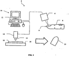
- Figure 1 is a diagrammatic view schematically illustrating the preferred embodiment of the artificial fingernail production system of the present invention
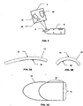
- Figure 2 is a diagrammatic view illustrating components of a measuring system of the present invention system
- Figure 3A is a cross sectional view along the nail length direction of an artificial fingernail of the present invention system
- Figure 3B is a cross sectional view along the nail width direction of the artificial fingernail of the present invention system
- Figure 3C is a top elevational view of the artificial fingernail of the present invention system
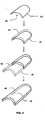
- Figure 4 is a diagrammatic view illustrating the steps employed in the process of the present invention system for digitally creating artificial fingernails
- Figure 5 is a diagrammatic view illustrating the steps of creating CNC machine usable codes in the present invention system
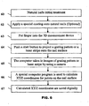
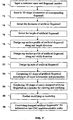
- Figure 6 is a flow diagram of the measurement process of the present invention system for measuring a natural fingernail
- Figure 7 is a flow diagram of the computer logic employed in the present invention system for how to design the shape of the artificial fingernail;
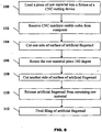
- Figure 8 is a flow diagram of the machining process of the present invention system for the artificial fingernails.
- Figure 9 is a flow diagram of applying nail polish or creating nail art onto the artificial fingernail of the present invention system.
- an artificial fingernail production system 2 of the present invention comprises an optical measuring device 4 for measuring the topography and dimensions of a fingernail 6 of a finger 8.
- the optical measuring device 4 is of the type known by those skilled in the relevant art.
- the optical measuring device may be the type as disclosed in U.S. Patent No. 5,175,601 , entitled High-Speed 3-D Surface Measurement Surface Inspection and Reverse-CAD System.
- the optical measuring device 4 is connected to a measuring and design system 10 comprising a computer system 12.
- the measuring and design system 10 is connected to a machining device 14 with a machining tool 16 for machining a material 18 that is mounted on a base 20 into an artificial fingernail 22.
- the machining device 14 in an embodiment, is a computer-numerically-controlled (CNC) device such as known by those skilled in the relevant art.
- the machining device 14 may be of the type that is disclosed in U.S. Patent No. 5,493,502 , entitled Numerical Control Unit for Controlling a Machine Tool to Machine a Workpiece at an Instructed Along Linear and Rotational Axes.
- the computer system 12 comprises a microprocessor based computer attached to a monitor, keyboard and pointing device, for example, a mouse.
- the computer has storage devices for example a hard drive and RAM for storing and reading application programs and data.
- the optical measuring device 4 of the artificial fingernail production system 2 comprises a camera 24, a light source 26 and a projection lens 28.
- the camera 24 is either an analog or digital video camera with an imaging capability as an area type or line type imager.
- the light source 26 is a white light for projecting a grid (not shown) onto the fingernail 6. While the grid is projected onto the fingernail 6, the camera 24 is used to take a picture or pictures of the grid. The picture or pictures are then transferred to the measuring and design system 10 for calculating the three-dimensional topography of the fingernail 6.
- the light source 26 is a laser used to measure the three-dimensional topography of the fingernail 6.
- the laser light source 26 scans a stripe across the fingernail 6 and the camera 24 records the image.
- a laser triangulation algorithm is then used to determine the three-dimensional topography of the fingernail 6.
- the laser scanning can be achieved by translating the light source 26 or by shifting the fingernail 6.
- Other ways of scanning the fingernail 6 with a laser light source 26 can alternately be used including by rotating a mirror (not shown) for rotatably scanning the laser across the fingernail 6 without movement of the light source 26.
- the imaging and scanning process are advantageously brief, allowing a user of the artificial fingernail production system 2 to quickly scan and measure the three-dimensional topography of a plurality of fingernails.
- the grid that is projected onto the fingernail 6 will deform in accordance with the topography of the fingernail 6.
- the deformations of the grid of the fingernail 6 are recorded by the camera 24 as a two-dimensional grid image.
- Different algorithms can be used to decode this two-dimensional deformed grid image into a three-dimensional topography of the fingernail 6.
- Algorithms for decoding the two-dimensional deformed grid image include: phase shifting; Fourier transforming; spatial coding; and Sinusoidal fitting. These algorithms will provide a phase map at the end of the calculation which is converted into three-dimensional coordinates for each pixel of the grid image. These calculations are performed by the measuring and design system 10.
- Both the laser scanning and white light grid methods will generate a set of points with known x, y, and z axis coordinates to represent the three-dimensional topography of the fingernail 6.
- the x, y, and z coordinates also define the boundary between the finger 8 and the fingernail 6.
- the x, y, and z axis coordinates are saved in the computer system's 12 storage capacity in a digital format.
- the boundary of the fingernail 6 can be determined by one of the following ways: (1) drawing an outline of the fingernail 6 of the finger 8 on the screen of the computer monitor by using the pointing device; or (2) automatically determining the boundary of the fingernail 6 by a boundary extraction algorithm. Both methods are well known to those skilled in the relevant art.
- the process for creating a custom fit artificial fingernail with a non-contact measuring device starts in step 60 with the treatment of the fingernail 6 to allow a more accurate measurement of the fingernail 6. This involves removing excess cuticle and cutting the fingernail 6 to an appropriate length.
- the fingernail 6 is covered with a coating.
- the coating is applied to create an optically diffusive surface on the fingernail 6.
- Any suitable coating can be used.
- a suitable coating is SKD-S2 from MagnaFluxTM. Step 62 of applying the coating on the fingernail 6 is not required and can be omitted.
- step 63 the fingernail 6 is placed in the optical measuring device 4 for measuring the three-dimensional topography of the fingernail 6.
- the optical measuring device 4 is then activated in step 64 and in step 65 the optical measuring device 4 takes an image of the fingernail 6 with the camera 24 while a grid or laser beam is projected onto the fingernail 6.
- step 66 the measuring and design system 10 calculates x, y, and z coordinates for the fingernail 6.
- step 67 the calculated coordinates are saved to the computer system 12 of the measuring and design system 10.
- the artificial fingernail 22 will have at least a portion of its undersurface that matches at least a portion of the corresponding fingernail 6.
- the artificial fingernail 22 has an underside 30 (with a solid line representing the portion that conforms to the topographical surface of the fingernail 6).
- a top side 32 of the artificial fingernail 22 (shown in broken line) corresponds to the portion of the artificial fingernail 22 that is custom designed as part of the processes of the invention.
- a back 34 and side 36 of the artificial fingernail 22 match the outer boundary of the fingernail 6 on the finger 8. Since only the underside 30 of the artificial fingernail 22 matches the three-dimensional topography of the fingernail 6 the remaining portion may be advantageously designed in whatever shape is desired.
- a design process is used to carry out the digital design of the artificial fingernail 22.
- This includes a first step 70 of inputting a customer name and fingernail number into the measuring and design system 10 for matching to and uniquely identifying the three-dimensional topographical measurement of the fingernail 6.
- step 72 the three-dimensional topographical information of the fingernail 6 is then selected.
- a desired thickness in step 74 and a length in step 76 of the artificial fingernail 22 are selected.
- the design profiles for the top side 32 of the artificial fingernail 22 in both nail length, in step 78, and width, in step 80, directions are selected.
- the style in step 82 of the artificial fingernail 22 is selected. With the information selected pursuant to steps 74-82 the artificial fingernail shape can be calculated in step 84 based on the input parameters and the three-dimensional topographical data for the fingernail 6.
- Figure 4 illustrates the steps for creating a three-dimensional data structure for the artificial fingernail 22. Illustrated first is a representation of the three-dimensional topographical data 42 that defines the topography of the fingernail 6. A top surface 44 is created from this based on the selected thickness and the chosen top surface profiles in both nail length and width directions. Next, the top surface 44 and the underside 30 formed from the three-dimensional topographical data 42 are used to define an extended top surface 46 and an extended undersurface 48. This step completes the process to create an artificial fingernail 22 which now has an integral extended top surface 46.
- the design system 40 will use the three-dimensional data structure of the resulting three-dimensional model of the artificial fingernail 22 to generate machine usable codes for machining an artificial fingernail as indicated in step 90.
- a machining process of the artificial fingernail production system 2 starts with providing a material 18 for machining.
- a series of cross-sectional lines 50 are generated along either the intended nail width or nail length direction at a predetermined spacing.
- the best position of the machining tool 16 is calculated at certain step sizes to create a three-dimensional cutter path 52.
- the three-dimensional cutter path 52 data is saved as a series of codes in a form readable by a machining device 14 such as a CNC machine.
- the material 18 for making the artificial fingernail 22 can advantageously be any desirable and suitable plastic, metal or other material.
- the machining device 14 will have at least three motor-driven translation axes perpendicular to each other.
- the machining tool 16 is capable of being controllably positioned along at least two perpendicular directions.
- the material 18 is provided in a rectangular shape with a length, width and height sufficient to accommodate the finished artificial fingernail 22. Referring to Figure 8 , in a first step 100 of the machining process, the material 18 is loaded into the machine device 14 (the CNC machine). Next, in step 102, machine usable codes created in step 90 are received by the machining device 14. Next, in step 104, one side of the surface of the material 18 for the artificial fingernail 22 is cut.
- step 106 This is followed in step 106 by rotating the material 18, 180 degrees for cutting, in step 108, the other side of the artificial fingernail 22.
- step 104 and step 108 two dimensional or three dimensional decorative designs or indicia, e.g. numbers, letters, etc., can be machined.
- the artificial fingernail 22 is next released from any remaining material 18 in step 110.
- step 112 any necessary finish filing of the artificial fingernail 22 is performed.
- an artificial fingernail 22 of the artificial fingernail production system 2 is produced.
- the artificial fingernail can next be coated with a design using an inkjet printing apparatus.
- the inkjet printing apparatus can be for example an inkjet printer by ImagiNailTM Corporation.
- a base coat is applied on the top surface of the artificial fingernail 22 before any nail art can be printed by using an inkjet printing apparatus.
- the base coating is used as a color-receiving agent to prevent ink from smearing.
- the artificial fingernail can be loaded into the inkjet printing apparatus.
- Desired nail art has to be chosen from a digital nail art collection saved on the computer system 12. Alternatively, nail art can be provided in a digital picture format in step 126.
- the inkjet printing apparatus will sense the size and position of the loaded artificial fingernail in step 124, and will resize the chosen nail art to match the size of the artificial fingernail in step 128. After confirmation, the nail art can be printed out onto the artificial fingernail surface in step 130.
- the inkjet printing apparatus has at least two motor-driven axes, and multiple color ink tanks. After removing the artificial fingernail from the inkjet printing apparatus in step 132, the final step is to apply a clear coating on the artificial fingernail to protect the nail art in step 134.
Landscapes
- Length Measuring Devices By Optical Means (AREA)
- Prostheses (AREA)
Abstract
Description
- The present invention generally relates to creating custom fit artificial fingernails and specifically to a process and system for creating custom fit artificial fingernails using a non-contact measuring device for measuring a fingernail for custom fitting an artificial fingernail.
- Artificial fingernail tips, a desirable fashion (if not also functional) accessory, exist in various forms. A customized artificial fingernail can be made to fit the exact contour and dimensions of a natural fingernail. This offers considerable advantages in comfort, appearance, and durability over non-custom fit fingernails commonly available. However, custom fitting an artificial fingernail poses special challenges and problems. Commonly used methods for production of artificial fingernails are very labor intensive, time consuming and require significant skill.
- One method for production of artificial fingernails is called "nail sculpturing." In this method a pre-made artificial fingernail tip is attached to the tip of a real finger by an adhesive or a supporting sheet. The supporting sheet is attached just under the tip of a real finger, then a thermoset material (mainly acrylic type) is then applied little by little onto the natural fingernail from the cuticle of the natural finger and sculpted to cover the whole artificial fingernail tip or a portion of the supporting sheet, such that a uniform extended surface is created. This process is repeated for each finger. Once the thermoset material dries naturally or under ultraviolet lighting, intensive and abrasive filing is applied to create a desired shape for each fingernail. Since this method builds up an artificial fingernail by adding material little by little manually, it gained the name of "nail sculpture." The last step of this process is to paint the top surface of the artificial fingernails with nail polish to display the desired color or pattern.
- Another method to create artificial fingernails is called "nail wrapping." In this method, fabric pieces are cut off and glued onto a natural fingernail. After a few layers of fabric are glued and dried, coats of filler material are applied to create a continuous uniform surface. After intensive filing to the desired shape, the nail can be polished. This process has to be repeated on each finger. Both nail sculpturing and nail wrapping expose the user and nail technicians to fumes, chemical liquids, and filing debris, which can present health and respiratory problems. In addition, the growth of a natural nail will create a gap between its cuticle and applied artificial fingernail since the artificial fingernail, once applied, is bonded onto the natural nail surface. This gap needs to be filled regularly, and this process requires a great deal of time and money.
- A less expensive alternative to the nail sculpturing and nail wrapping methods is the pre-made artificial fingernail tips with nail art already in place that are capable of being pasted onto the natural fingernail. However, such mass-produced artificial fingernail tips have limited choices in their shapes, lengths, styles and fit. A person's fingernail is different from another person's in its cuticle, width, length, and three-dimensional (3D) shape. Therefore, mass-produced artificial fingernail tips cannot fit exactly to a user's natural fingernail. Usually, such an artificial fingernail tip is forced onto a natural fingernail surface, and glued on with an adhesive. This poses the problem that such an artificial fingernail tip can be peeled easily. In addition, this type of artificial fingernail tip is usually recognized as false due to the unfitted shape at the margins.
- Another option that solves the problems encountered in the existing pre-made artificial fingernail tips and the nail sculpturing and nail wrapping methods as described above, is to custom manufacture every artificial fingernail tip. This process may consist of creating a plaster mold from a series of precise impressions of a natural fingernail, then the mold can be used to create an artificial fingernail by either injection molding or casting. The creation of artificial nails by using this process is still time consuming, costly and requires considerable work to turn the rough cast into the finished product. It is also impractical to perform this process in a nail salon environment.
- Other proposed processes require contact with the person's fingernail to measure the fingernail for custom fitting. These systems would inherently be less accurate than non-touch measuring systems and require a mechanical apparatus that can be prone to malfunction.
EP 0 577 515 (A1 ) discloses a system using information taken from a sensing device sensing the dimensions of an existing fingernail structure and inputting this sensed information into a controller in machine usable form. The data is used by the controller to drive a variety of peripheral devices to cut a desired nail pattern in a material so that at least a part of the material snugly fits over the existing nail structure. The system is further capable of cutting a sheet of decorative material to the shape of a natural nail or one that is artificially placed on a nail. The decorative sheet may be formed of vinyl or mylar and has an adhesive layer which binds it to the involved nail.
US 6,035,860 discloses a system for applying artwork to fingernails having a computer controller, a hand mold to securely hold the user's fingernails, a device for determining the size and location of the fingernails, and an applicator for applying the artwork. A method for applying artwork to fingernails provides color and/or design choices selected from a computer media catalogue of colors and designs. A user views these choices on a video monitor, which also displays messages to guide the user through the application process. Prior to application of the artwork, the fingernails are coated with a light reactive base coat. The user's hands are inserted into a hand mold in which a height sensor and height gauge aid in positioning the fingernails at a preferred height position. The hand mold is retracted into a main system module in which an optical sensor detects the light reactive base coating for determining the size, peripheral shape, and location of the fingernails. A color applicator in the main system module applies the user selected artwork directly to the user's fingernails.
US 6,328,949 discloses a method for making nail coverings comprising the steps of scanning a persons fingernail to produce a digitized nail image of the nail top surface and shaping a nail covering material using the digitized nail image such that the nail covering material conforms to the nail top surface thereby producing a nail cover sized to cover substantially the entire nail top surface. The method preferably includes the step of adhering the nail cover to the nail top surface thereby covering substantially the entire nail top surface with the nail cover. The method preferably includes the further step of producing a three dimensional digital nail image of the nail top surface. - In accordance with the present invention, a preferred embodiment provides an artificial fingernail production system for creating custom fit artificial fingernails. In another aspect of the present invention, the system comprises a non-contact measuring system for measuring dimensions of a fingernail wherein the non-contact measuring system comprises a non-contact measuring device for measuring a three-dimensional topography of a fingernail. A further aspect of the present invention employs a machining device for creating an artificial fingernail using the three-dimensional topography of the fingernail wherein the resulting artificial fingernail custom fits the fingernail. Yet another aspect of the present invention provides a light source for emitting a white light onto the fingernail and a camera for recording an image of the fingernail. In a further aspect of the present invention, the light source may project a grid onto the fingernail and take a picture of the grid for calculating the three-dimensional topography. In a separate embodiment a laser can be used as the light source for scanning the surface of the fingernail. Data from either the white light embodiment or the laser embodiment of the light source is converted into a three-dimensional topographical data structure for the fingernail. In a further aspect of the invention, a preferred embodiment provides a process for custom designing an artificial fingernail comprising the steps of measuring a three-dimensional topography of a fingernail with a non-contact measuring system, selecting parameters for the artificial fingernail wherein the parameters include thickness, length and style of the artificial fingernail, and then calculating a three-dimensional shape of the artificial fingernail from the three-dimensional topography of the fingernail and the parameters for the artificial fingernail. In a preferred embodiment this process also includes machining the artificial fingernail for custom fitting the fingernail.
- In operation, a system user for one aspect of the present invention presents a finger or fingers for custom measuring where a non-contact measuring device measures the topography of the fingernail for each finger. This can then be repeated for each other finger or fingers as desired. The resulting data from the measurement is converted into a three-dimensional image for viewing by the user together with a proposed artificial fingernail. The user is then allowed to select options for designing a customized artificial fingernail. Once the desired options are selected the three-dimensional data for the artificial fingernail is converted into a machine code and transferred to a machine such as a computer numerically controlled machine for cutting the artificial fingernail from a raw material into the desired shape that provides a custom fit to the system user.
- Thus, a system and process is provided for quickly and accurately measuring and custom fitting artificial fingernails. The system offers the opportunity of measuring for, designing, and producing custom fingernails within a short period of time. The system is advantageously small and suitable for use in a salon where custom fingernail design is already offered.
- Therefore, an advantage of the present invention is to provide a system and process for creating custom crafted artificial fingernail tips by using an automated system with a non-contact measuring system. A further advantage of the invention is to provide a safe, convenient, accurate, and rapid system for measuring the topographical shape and dimensions of a natural fingernail and producing a custom fit artificial fingernail. It is yet a further advantage of the present invention to provide a method to digitally design an artificial fingernail incorporating the digitized three-dimensional shape of a natural fingernail.
- Further areas of applicability of the present invention will become apparent from the detailed description provided hereinafter.
- The present invention will become more fully understood from the detailed description and the accompanying drawings, wherein:
-
Figure 1 is a diagrammatic view schematically illustrating the preferred embodiment of the artificial fingernail production system of the present invention; -
Figure 2 is a diagrammatic view illustrating components of a measuring system of the present invention system; -
Figure 3A is a cross sectional view along the nail length direction of an artificial fingernail of the present invention system; -
Figure 3B is a cross sectional view along the nail width direction of the artificial fingernail of the present invention system; -
Figure 3C is a top elevational view of the artificial fingernail of the present invention system; -
Figure 4 is a diagrammatic view illustrating the steps employed in the process of the present invention system for digitally creating artificial fingernails; -
Figure 5 is a diagrammatic view illustrating the steps of creating CNC machine usable codes in the present invention system; -
Figure 6 is a flow diagram of the measurement process of the present invention system for measuring a natural fingernail; -
Figure 7 is a flow diagram of the computer logic employed in the present invention system for how to design the shape of the artificial fingernail; -
Figure 8 is a flow diagram of the machining process of the present invention system for the artificial fingernails; and -
Figure 9 is a flow diagram of applying nail polish or creating nail art onto the artificial fingernail of the present invention system. - The following description of the preferred embodiment(s) is merely exemplary in nature and is in no way intended to limit the invention, its application, or uses.
- Referring to
Figure 1 , an artificialfingernail production system 2 of the present invention comprises anoptical measuring device 4 for measuring the topography and dimensions of afingernail 6 of afinger 8. Theoptical measuring device 4 is of the type known by those skilled in the relevant art. For example, the optical measuring device may be the type as disclosed inU.S. Patent No. 5,175,601 , entitled High-Speed 3-D Surface Measurement Surface Inspection and Reverse-CAD System. Theoptical measuring device 4 is connected to a measuring anddesign system 10 comprising acomputer system 12. The measuring anddesign system 10 is connected to amachining device 14 with amachining tool 16 for machining amaterial 18 that is mounted on a base 20 into anartificial fingernail 22. Themachining device 14 in an embodiment, is a computer-numerically-controlled (CNC) device such as known by those skilled in the relevant art. For example, themachining device 14 may be of the type that is disclosed inU.S. Patent No. 5,493,502 , entitled Numerical Control Unit for Controlling a Machine Tool to Machine a Workpiece at an Instructed Along Linear and Rotational Axes. Thecomputer system 12 comprises a microprocessor based computer attached to a monitor, keyboard and pointing device, for example, a mouse. The computer has storage devices for example a hard drive and RAM for storing and reading application programs and data. - Referring now to
Figure 2 , theoptical measuring device 4 of the artificialfingernail production system 2 comprises acamera 24, alight source 26 and aprojection lens 28. Thecamera 24 is either an analog or digital video camera with an imaging capability as an area type or line type imager. Thelight source 26 is a white light for projecting a grid (not shown) onto thefingernail 6. While the grid is projected onto thefingernail 6, thecamera 24 is used to take a picture or pictures of the grid. The picture or pictures are then transferred to the measuring anddesign system 10 for calculating the three-dimensional topography of thefingernail 6. - In a second preferred embodiment the
light source 26 is a laser used to measure the three-dimensional topography of thefingernail 6. In this embodiment, thelaser light source 26 scans a stripe across thefingernail 6 and thecamera 24 records the image. A laser triangulation algorithm is then used to determine the three-dimensional topography of thefingernail 6. The laser scanning can be achieved by translating thelight source 26 or by shifting thefingernail 6. Other ways of scanning thefingernail 6 with alaser light source 26 can alternately be used including by rotating a mirror (not shown) for rotatably scanning the laser across thefingernail 6 without movement of thelight source 26. In either the white light embodiment of thelight source 26 or the laser embodiment of thelight source 26 the imaging and scanning process are advantageously brief, allowing a user of the artificialfingernail production system 2 to quickly scan and measure the three-dimensional topography of a plurality of fingernails. - When using the white light embodiment of the
light source 26, the grid that is projected onto thefingernail 6 will deform in accordance with the topography of thefingernail 6. The deformations of the grid of thefingernail 6 are recorded by thecamera 24 as a two-dimensional grid image. Different algorithms can be used to decode this two-dimensional deformed grid image into a three-dimensional topography of thefingernail 6. Algorithms for decoding the two-dimensional deformed grid image include: phase shifting; Fourier transforming; spatial coding; and Sinusoidal fitting. These algorithms will provide a phase map at the end of the calculation which is converted into three-dimensional coordinates for each pixel of the grid image. These calculations are performed by the measuring anddesign system 10. Both the laser scanning and white light grid methods will generate a set of points with known x, y, and z axis coordinates to represent the three-dimensional topography of thefingernail 6. The x, y, and z coordinates also define the boundary between thefinger 8 and thefingernail 6. By using these non-contact methods, the total number of points measured for a fingernail can be easily over 200,000 points. The x, y, and z axis coordinates are saved in the computer system's 12 storage capacity in a digital format. - The boundary of the
fingernail 6 can be determined by one of the following ways: (1) drawing an outline of thefingernail 6 of thefinger 8 on the screen of the computer monitor by using the pointing device; or (2) automatically determining the boundary of thefingernail 6 by a boundary extraction algorithm. Both methods are well known to those skilled in the relevant art. - Referring to
Figure 6 the process for creating a custom fit artificial fingernail with a non-contact measuring device starts instep 60 with the treatment of thefingernail 6 to allow a more accurate measurement of thefingernail 6. This involves removing excess cuticle and cutting thefingernail 6 to an appropriate length. Next, instep 62 thefingernail 6 is covered with a coating. The coating is applied to create an optically diffusive surface on thefingernail 6. Any suitable coating can be used. For example, a suitable coating is SKD-S2 from MagnaFlux™.Step 62 of applying the coating on thefingernail 6 is not required and can be omitted. Following this, instep 63 thefingernail 6 is placed in theoptical measuring device 4 for measuring the three-dimensional topography of thefingernail 6. Theoptical measuring device 4 is then activated instep 64 and instep 65 theoptical measuring device 4 takes an image of thefingernail 6 with thecamera 24 while a grid or laser beam is projected onto thefingernail 6. Then instep 66 the measuring anddesign system 10 calculates x, y, and z coordinates for thefingernail 6. Finally, instep 67 the calculated coordinates are saved to thecomputer system 12 of the measuring anddesign system 10. - After the measurement of the fingernail is done the next step is the design of the
artificial fingernail 22. Theartificial fingernail 22 will have at least a portion of its undersurface that matches at least a portion of thecorresponding fingernail 6. Referring briefly toFigures 3A, and 3B , theartificial fingernail 22 has an underside 30 (with a solid line representing the portion that conforms to the topographical surface of the fingernail 6). Atop side 32 of the artificial fingernail 22 (shown in broken line) corresponds to the portion of theartificial fingernail 22 that is custom designed as part of the processes of the invention. Referring toFigure 3C , a back 34 andside 36 of theartificial fingernail 22, match the outer boundary of thefingernail 6 on thefinger 8. Since only theunderside 30 of theartificial fingernail 22 matches the three-dimensional topography of thefingernail 6 the remaining portion may be advantageously designed in whatever shape is desired. - Now referring to
Figure 7 , a design process is used to carry out the digital design of theartificial fingernail 22. This includes afirst step 70 of inputting a customer name and fingernail number into the measuring anddesign system 10 for matching to and uniquely identifying the three-dimensional topographical measurement of thefingernail 6. Instep 72 the three-dimensional topographical information of thefingernail 6 is then selected. Next, a desired thickness instep 74 and a length instep 76 of theartificial fingernail 22 are selected. Following this, the design profiles for thetop side 32 of theartificial fingernail 22 in both nail length, instep 78, and width, instep 80, directions are selected. Next, the style instep 82 of theartificial fingernail 22 is selected. With the information selected pursuant to steps 74-82 the artificial fingernail shape can be calculated instep 84 based on the input parameters and the three-dimensional topographical data for thefingernail 6. -
Figure 4 illustrates the steps for creating a three-dimensional data structure for theartificial fingernail 22. Illustrated first is a representation of the three-dimensionaltopographical data 42 that defines the topography of thefingernail 6. Atop surface 44 is created from this based on the selected thickness and the chosen top surface profiles in both nail length and width directions. Next, thetop surface 44 and theunderside 30 formed from the three-dimensionaltopographical data 42 are used to define an extendedtop surface 46 and anextended undersurface 48. This step completes the process to create anartificial fingernail 22 which now has an integral extendedtop surface 46. - Returning to
Figure 7 , after a three-dimensional model of theartificial fingernail 22 has been created, it will be displayed for viewing and verifying purposes instep 86. If necessary, modifications to the display design can be performed as indicated instep 88. - After the three-dimensional design of the
artificial fingernail 22 is approved, the design system 40 will use the three-dimensional data structure of the resulting three-dimensional model of theartificial fingernail 22 to generate machine usable codes for machining an artificial fingernail as indicated instep 90. - Referring to
Figure 5 , a machining process of the artificialfingernail production system 2 starts with providing amaterial 18 for machining. A series ofcross-sectional lines 50 are generated along either the intended nail width or nail length direction at a predetermined spacing. Based on the profile of the cross-sectional lines, the best position of themachining tool 16 is calculated at certain step sizes to create a three-dimensional cutter path 52. Finally, the three-dimensional cutter path 52 data is saved as a series of codes in a form readable by amachining device 14 such as a CNC machine. - The
material 18 for making theartificial fingernail 22 can advantageously be any desirable and suitable plastic, metal or other material. - The
machining device 14 will have at least three motor-driven translation axes perpendicular to each other. Themachining tool 16 is capable of being controllably positioned along at least two perpendicular directions. Thematerial 18 is provided in a rectangular shape with a length, width and height sufficient to accommodate the finishedartificial fingernail 22. Referring toFigure 8 , in afirst step 100 of the machining process, thematerial 18 is loaded into the machine device 14 (the CNC machine). Next, instep 102, machine usable codes created instep 90 are received by themachining device 14. Next, instep 104, one side of the surface of thematerial 18 for theartificial fingernail 22 is cut. This is followed instep 106 by rotating thematerial step 108, the other side of theartificial fingernail 22. Instep 104 and step 108, two dimensional or three dimensional decorative designs or indicia, e.g. numbers, letters, etc., can be machined. Theartificial fingernail 22 is next released from any remainingmaterial 18 instep 110. Finally, instep 112, any necessary finish filing of theartificial fingernail 22 is performed. Thus, anartificial fingernail 22 of the artificialfingernail production system 2 is produced. - Referring to
Figure 9 the artificial fingernail can next be coated with a design using an inkjet printing apparatus. The inkjet printing apparatus can be for example an inkjet printer by ImagiNail™ Corporation. In a first step (120) a base coat is applied on the top surface of theartificial fingernail 22 before any nail art can be printed by using an inkjet printing apparatus. The base coating is used as a color-receiving agent to prevent ink from smearing. After the base coating dries, the artificial fingernail can be loaded into the inkjet printing apparatus. Desired nail art has to be chosen from a digital nail art collection saved on thecomputer system 12. Alternatively, nail art can be provided in a digital picture format instep 126. The inkjet printing apparatus will sense the size and position of the loaded artificial fingernail instep 124, and will resize the chosen nail art to match the size of the artificial fingernail instep 128. After confirmation, the nail art can be printed out onto the artificial fingernail surface instep 130. The inkjet printing apparatus has at least two motor-driven axes, and multiple color ink tanks. After removing the artificial fingernail from the inkjet printing apparatus instep 132, the final step is to apply a clear coating on the artificial fingernail to protect the nail art instep 134. - The preferred embodiments disclosed are used in conjunction with fingernails, but it is clearly within the purview of the invention to use the system to cover toenails as well. Accordingly, the invention has been described by way of illustration rather than limitation.
Claims (14)
- A system (2) for creating a custom fit, three-dimensional, artificial fingernail (22), wherein a portion of the artificial fingernail (22) retains a shape that substantially matches a top surface of a natural fingernail (6), the system (2) comprising:a non-contact measuring system (4) for measuring a three-dimensional topography of the natural fingernail (6), the measuring system (4) comprising a light source (26) and a camera (24);a design system (10) for designing the three-dimensional shape of the artificial fingernail (22) by offering a selection of parameters comprising length, and three-dimensional style, of the artificial fingernail (22);a calculation module (12) within the design system (10) for calculating a three-dimensional design of the artificial fingernail (22) from the three-dimensional topography of the natural fingernail (6) and the selected parameters; anda machining device (14) for creating the artificial fingernail (22) using the three-dimensional design of the artificial fingernail (22), the artificial fingernail (22) retaining the shape that substantially matches the top surface of the natural fingernail (6).
- The system (2) of claim 1 wherein the light source (26) is a white light, and the non-contact measuring system (4) receives at least one two-dimensional image of the natural fingernail (6) and calculates the three-dimensional topography of the natural fingernail (6).
- The system of claim 1 wherein the light source (26) is a laser, and the non-contact measuring system scans the natural fingernail (6) and calculates the three-dimensional topography of the natural fingernail (6).
- The system of claim 1 wherein the non-contact measuring system (4) converts the three-dimensional topography of the natural fingernail (6) into a machine code for the machining device (14).
- The system of claim 1 wherein the machining device (14) is a computer numerical control device for receiving machine data for milling a material into the artificial fingernail (22).
- A process for custom designing an artificial fingernail (22) for use with a natural fingernail (6), the process comprising:calculating x, y and z data points of the natural fingernail (6) with a non-contact measuring system (4);selecting parameters for the artificial fingernail (22), wherein the parameters selected comprise length, and style;calculating a three-dimensional shape of the artificial fingernail (22) from the x, y, and z data points of the natural fingernail (6) and the parameters for the artificial fingernail (22); andmachining the artificial fingernail (22) wherein the artificial fingernail (22) custom fits the natural fingernail (6).
- The process of claim 6, further comprising:converting the three-dimensional shape of the artificial fingernail (22) into a machine data for the machining of the artificial fingernail (22).
- The process of claim 6 wherein the machine data are machine codes.
- The process of claim 6, further comprising:displaying the three-dimensional shape of the artificial fingernail (22) before machining the artificial fingernail (22).
- A computer-readable medium for designing a custom artificial fingernail (22) for fitting a natural fingernail (6) based on an optical image of the natural fingernail (6), comprising a set of executable instructions adapted to manipulate a system (2) to:receive from an optical imaging device (4) image data defining a surface of a finger (8) comprising a surface of a natural fingernail (6);extract from the image data a portion of image data that defines x, y, and z data points of the surface of the natural fingernail (6);select a design for the artificial fingernail (22);create a three-dimensional data structure for the artificial fingernail (22) wherein the data structure comprises the x, y, and z data points that define the surface of the natural fingernail (6) and the design for the artificial fingernail (22); andconvert the three-dimensional data structure into machine data for cutting the artificial fingernail (22) out of a material.
- The computer-readable medium of claim 10 wherein the image data defines a surface of a plurality of fingers (8) comprising a plurality of surfaces of natural fingernails (6).
- The computer-readable medium of claim 10 wherein creating the three-dimensional data structure further comprises:defining a top surface of the artificial fingernail (22) wherein a portion of the top surface corresponds to the boundary of the surface of the natural fingernail (6);defining a length of the artificial fingernail (22);defining a thickness of the artificial fingernail (22); anddefining a style of the artificial fingernail (22).
- The computer-readable medium of claim 10 wherein the three-dimensional data structure is converted into machine codes readable by a computer numerically controlled device for cutting the artificial fingernail (22) out of the material.
- The computer-readable medium of claim 10 wherein the machine data are machine codes suitable for a computer numerically controlled machine.
Applications Claiming Priority (3)
| Application Number | Priority Date | Filing Date | Title |
|---|---|---|---|
| US42595202P | 2002-11-13 | 2002-11-13 | |
| US425952P | 2002-11-13 | ||
| PCT/US2003/036380 WO2004043200A1 (en) | 2002-11-13 | 2003-11-13 | A system and process for creating custom fit artificial fingernails using a non-contact optical measuring device |
Publications (2)
| Publication Number | Publication Date |
|---|---|
| EP1581076A1 EP1581076A1 (en) | 2005-10-05 |
| EP1581076B1 true EP1581076B1 (en) | 2012-04-25 |
Family
ID=32313084
Family Applications (1)
| Application Number | Title | Priority Date | Filing Date |
|---|---|---|---|
| EP03783459A Expired - Lifetime EP1581076B1 (en) | 2002-11-13 | 2003-11-13 | A system and process for creating custom fit artificial fingernails using a non-contact optical measuring device |
Country Status (5)
| Country | Link |
|---|---|
| US (1) | US7123983B2 (en) |
| EP (1) | EP1581076B1 (en) |
| JP (1) | JP4610341B2 (en) |
| AT (1) | ATE554675T1 (en) |
| WO (1) | WO2004043200A1 (en) |
Families Citing this family (65)
| Publication number | Priority date | Publication date | Assignee | Title |
|---|---|---|---|---|
| WO2004022345A1 (en) * | 2002-09-03 | 2004-03-18 | Mastermind Co., Ltd. | Printing system using ink-jet printer |
| US20060033758A1 (en) * | 2004-08-15 | 2006-02-16 | Nielson Scott L | A method, process and computer program to automatically create a customized three-dimensional nail object by morphing |
| US20090092310A1 (en) * | 2004-02-06 | 2009-04-09 | Gifford Craig P | System and method for precision fit artificial fingernails |
| US7526416B2 (en) * | 2004-08-15 | 2009-04-28 | American Equities Management, Llc | Method, process and computer program to automatically create a customized three-dimensional nail object by welding |
| US20060034507A1 (en) * | 2004-08-16 | 2006-02-16 | Nielson Scott L | A method, process and computer program to automatically create a customized three-dimensional nail object by library reference |
| US7536286B2 (en) * | 2004-08-14 | 2009-05-19 | American Equities Management, Llc | Method, process and computer program to automatically create a customized three-dimensional nail object |
| WO2005076997A2 (en) * | 2004-02-06 | 2005-08-25 | Nielson Scott L | Distinguishing a nail surface from surrounding tissue |
| CN100412904C (en) * | 2006-09-30 | 2008-08-20 | 吴宁 | A method for changing nail art patterns in real time |
| WO2007076683A1 (en) * | 2005-12-30 | 2007-07-12 | Ning Wu | Method for selecting and real time changing a nail beautifying pattern |
| ATE537727T1 (en) | 2006-09-29 | 2012-01-15 | Janice Jordan | METHOD AND APPARATUS FOR APPLYING SOLID NAIL COATINGS ON MAMMAL AND ARTIFICIAL NAILS |
| CN106175030A (en) * | 2009-01-16 | 2016-12-07 | 宝洁公司 | Change equipment and the method for keratinous surfaces |
| US8757171B2 (en) * | 2009-10-06 | 2014-06-24 | Mattel, Inc. | Finger positioning device for a printer |
| US20110087351A1 (en) * | 2009-10-09 | 2011-04-14 | Rohit Sachdeva | Customized artificial nail |
| FR2964305B1 (en) | 2010-09-06 | 2019-06-28 | L'oreal | METHOD FOR MANUFACTURING CUSTOM COSMETIC ARTICLES, IN PARTICULAR FALSE NAILS AND ARTICLES THUS PRODUCED |
| TW201212852A (en) * | 2010-09-21 | 2012-04-01 | Zong Jing Investment Inc | Facial cosmetic machine |
| US8590543B2 (en) | 2010-11-17 | 2013-11-26 | Mattel, Inc. | Hair extension kit |
| JP5732840B2 (en) * | 2010-12-14 | 2015-06-10 | カシオ計算機株式会社 | Nail printing apparatus and printing control method |
| JP5803096B2 (en) * | 2010-12-14 | 2015-11-04 | カシオ計算機株式会社 | Nail printing apparatus and printing control method |
| JP5732916B2 (en) * | 2011-03-03 | 2015-06-10 | カシオ計算機株式会社 | Nail printing apparatus and printing control method |
| JP5494562B2 (en) * | 2011-04-28 | 2014-05-14 | カシオ計算機株式会社 | Curved surface printing apparatus and printing control method for curved surface printing apparatus |
| JP5338848B2 (en) * | 2011-05-09 | 2013-11-13 | カシオ計算機株式会社 | Nail printing apparatus and printing control method for nail printing apparatus |
| JP5402980B2 (en) * | 2011-05-09 | 2014-01-29 | カシオ計算機株式会社 | Nail printing apparatus and printing control method for nail printing apparatus |
| DE102011114674C5 (en) * | 2011-09-30 | 2020-05-28 | Steinbichler Optotechnik Gmbh | Method and device for determining the 3D coordinates of an object |
| JP2013094184A (en) * | 2011-10-28 | 2013-05-20 | Casio Computer Co Ltd | Nail print apparatus |
| TWI463955B (en) * | 2012-02-20 | 2014-12-11 | Zong Jing Investment Inc | Eye makeup device |
| WO2013145040A1 (en) * | 2012-03-30 | 2013-10-03 | パナソニック株式会社 | Nail tip manufacturing system and nail tip manufacturing method |
| KR101616856B1 (en) | 2012-09-05 | 2016-05-11 | 아프레시아 파마슈티칼스 컴퍼니 | Three-dimensional printing system and equipment assembly |
| US9227359B2 (en) * | 2012-12-31 | 2016-01-05 | Yong Li | System and method for manufacturing custom-fit three-dimensional artificial nails |
| US9398797B2 (en) * | 2012-12-31 | 2016-07-26 | Yong Li | Nail gauge measuring nail shape and nail arc length |
| AU2014228990B2 (en) | 2013-03-15 | 2017-02-02 | Aprecia Pharmaceuticals LLC | Rapid disperse dosage form containing levetiracetam |
| US11265444B2 (en) * | 2013-08-23 | 2022-03-01 | Preemadonna Inc. | Apparatus for applying coating to nails |
| US9687059B2 (en) * | 2013-08-23 | 2017-06-27 | Preemadonna Inc. | Nail decorating apparatus |
| US9189186B2 (en) | 2013-09-18 | 2015-11-17 | Jamberry Nails, LLC | Method and system for custom designing nail wraps |
| ES2844187T3 (en) * | 2013-12-31 | 2021-07-21 | Finails Oy | System and method for a nail manipulation |
| JP6439342B2 (en) * | 2014-09-22 | 2018-12-19 | カシオ計算機株式会社 | Nail information detection device, drawing device, and nail information detection method |
| JP6435749B2 (en) * | 2014-09-26 | 2018-12-12 | カシオ計算機株式会社 | Nail design display control device, nail print device, nail design display control method, and nail design display control program |
| CN118303714A (en) * | 2014-12-03 | 2024-07-09 | 南京美小甲科技有限公司 | Nail beauty device, nail beauty method and health management and information pushing method based on nail beauty device |
| JP6561462B2 (en) | 2014-12-19 | 2019-08-21 | カシオ計算機株式会社 | Nail printing apparatus and drawing method of nail printing apparatus |
| JP6428411B2 (en) * | 2015-03-18 | 2018-11-28 | カシオ計算機株式会社 | Drawing apparatus and nail inclination detection method |
| JP6428415B2 (en) * | 2015-03-20 | 2018-11-28 | カシオ計算機株式会社 | Drawing apparatus and nail shape detection method |
| BR112018001609A2 (en) | 2015-08-21 | 2018-09-18 | Aprecia Pharmaceuticals LLC | system and assembly of three-dimensional printing equipment |
| JP6529902B2 (en) * | 2015-12-22 | 2019-06-12 | 株式会社東芝 | Method of manufacturing artificial nails and artificial nails |
| WO2017174703A2 (en) | 2016-04-08 | 2017-10-12 | L'oreal | Process for manufacturing a false nail |
| US10765658B2 (en) | 2016-06-22 | 2020-09-08 | Mastix LLC | Oral compositions delivering therapeutically effective amounts of cannabinoids |
| JP6790513B2 (en) * | 2016-07-05 | 2020-11-25 | カシオ計算機株式会社 | Drawing device and drawing method of drawing device |
| CN109475213A (en) * | 2016-07-20 | 2019-03-15 | 索尼公司 | Order Receiving Device and Order Receiving Method |
| KR20190031478A (en) * | 2016-07-20 | 2019-03-26 | 소니 주식회사 | Nail Making System and Nail Making Method |
| CN106239052B (en) * | 2016-08-25 | 2019-02-22 | 黄世咸 | A kind of bumper repacking manufacturing process |
| JP7281414B2 (en) * | 2017-01-31 | 2023-05-25 | ネイロマティック リミテッド | Automatic nail polish applicator |
| CN110446664B (en) | 2017-01-31 | 2022-04-05 | 纽尔罗玛蒂克有限公司 | Brush integrated capsule with film forming polymer for nail polishing |
| US10806231B2 (en) * | 2017-07-18 | 2020-10-20 | Casio Computer Co., Ltd. | Drawing apparatus, drawing method, and recording medium storing program |
| CN109259411A (en) * | 2017-07-18 | 2019-01-25 | 曹可瀚 | Nail beauty machine and manicure method |
| JP7020020B2 (en) * | 2017-09-20 | 2022-02-16 | カシオ計算機株式会社 | Drawing data generator, drawing data generation method and program |
| WO2019070886A1 (en) | 2017-10-04 | 2019-04-11 | Preemadonna Inc. | Systems and methods of adaptive nail printing and collaborative beauty platform hosting |
| JP7124419B2 (en) * | 2018-04-25 | 2022-08-24 | カシオ計算機株式会社 | nail printing device |
| US20200105007A1 (en) * | 2018-09-28 | 2020-04-02 | Mani.Me, Inc. | Apparatus and method for model reconstruction using photogrammetry |
| WO2020176560A1 (en) * | 2019-02-28 | 2020-09-03 | Cochran Brianna Storm | Soluble 3d printed custom artificial nails designed through a mobile application |
| GB201913301D0 (en) * | 2019-09-14 | 2019-10-30 | Hoang Kim | A method for obtaining and storing information suitable for production of artificial nails for an individual |
| JP2023500675A (en) | 2019-10-29 | 2023-01-10 | ネイルプロ・インコーポレイテッド | Automatic total nail care system, device and method |
| WO2021156995A1 (en) * | 2020-02-06 | 2021-08-12 | ピー・シャイン株式会社 | Nail tip, system for producing same, and method for producing same |
| JP7571382B2 (en) * | 2020-03-24 | 2024-10-23 | カシオ計算機株式会社 | PRINTING APPARATUS, PRINTING APPARATUS CONTROL METHOD, AND CONTROL PROGRAM |
| US12583148B2 (en) * | 2020-04-07 | 2026-03-24 | Elham Al-Muslim | Artificial nail measurement system and method |
| WO2022198745A1 (en) * | 2021-03-24 | 2022-09-29 | Shanghai Huizi Cosmetics Co., Ltd. | Method and system for extracting nail contours |
| US12411999B2 (en) | 2021-10-15 | 2025-09-09 | Nimble Official Limited | Customized artificial fingernail generation systems |
| JP7620961B1 (en) * | 2024-07-24 | 2025-01-24 | 株式会社Dent-Ease | Artificial nail manufacturing method, artificial nail attachment method, and artificial nail manufacturing system |
Family Cites Families (14)
| Publication number | Priority date | Publication date | Assignee | Title |
|---|---|---|---|---|
| US32654A (en) * | 1861-06-25 | Melodeon | ||
| US4645348A (en) * | 1983-09-01 | 1987-02-24 | Perceptron, Inc. | Sensor-illumination system for use in three-dimensional measurement of objects and assemblies of objects |
| US5172601A (en) * | 1991-08-12 | 1992-12-22 | Hoover Universal, Inc. | Drive nut and screw for seat adjuster |
| JP3036143B2 (en) * | 1991-09-02 | 2000-04-24 | 三菱電機株式会社 | Numerical control unit |
| US5175601A (en) | 1991-10-15 | 1992-12-29 | Electro-Optical Information Systems | High-speed 3-D surface measurement surface inspection and reverse-CAD system |
| US5309365A (en) * | 1992-07-02 | 1994-05-03 | Gerber Scientific Products, Inc. | System for cutting artificial nail tips and for decorating the same or existing nails using automated cutting processes |
| US5968302A (en) * | 1997-05-16 | 1999-10-19 | Ova Nail Products, Inc. | Methods for manufacturing precision fit fingernails |
| US6328949B1 (en) | 1998-10-14 | 2001-12-11 | Dino Tessarolo | Nail covering system |
| JP3016147B1 (en) * | 1998-12-25 | 2000-03-06 | 株式会社アトラス | Nail art equipment |
| US6035860A (en) | 1999-01-14 | 2000-03-14 | Belquette Ltd. | System and method for applying fingernail art |
| JP3081598B1 (en) * | 1999-02-15 | 2000-08-28 | 悟 馬場 | How to make false nail chips |
| US6464496B1 (en) * | 1999-11-30 | 2002-10-15 | Orametrix, Inc. | Method and apparatus for determining and monitoring orthodontic treatment |
| CA2400748C (en) * | 2000-03-31 | 2009-10-20 | Imx Labs, Inc. | Nail polish color selection system and method |
| US6382217B2 (en) * | 2000-04-06 | 2002-05-07 | Wade Coker | Process for fabricating custom fit removable and reusable metal fingernails |
-
2003
- 2003-11-13 WO PCT/US2003/036380 patent/WO2004043200A1/en not_active Ceased
- 2003-11-13 JP JP2004552215A patent/JP4610341B2/en not_active Expired - Fee Related
- 2003-11-13 AT AT03783459T patent/ATE554675T1/en active
- 2003-11-13 EP EP03783459A patent/EP1581076B1/en not_active Expired - Lifetime
- 2003-11-13 US US10/712,547 patent/US7123983B2/en not_active Expired - Fee Related
Also Published As
| Publication number | Publication date |
|---|---|
| WO2004043200A1 (en) | 2004-05-27 |
| EP1581076A1 (en) | 2005-10-05 |
| JP4610341B2 (en) | 2011-01-12 |
| US7123983B2 (en) | 2006-10-17 |
| US20040143359A1 (en) | 2004-07-22 |
| ATE554675T1 (en) | 2012-05-15 |
| JP2006519030A (en) | 2006-08-24 |
Similar Documents
| Publication | Publication Date | Title |
|---|---|---|
| US7123983B2 (en) | System and process for creating custom fit artificial fingernails using a non-contact optical measuring device | |
| US20090092310A1 (en) | System and method for precision fit artificial fingernails | |
| AU2013409568B2 (en) | System and method for a nail manipulation | |
| EP1151778B1 (en) | Real 3-d model forming device | |
| US5309365A (en) | System for cutting artificial nail tips and for decorating the same or existing nails using automated cutting processes | |
| EP4027829B1 (en) | A method for obtaining and storing information suitable for production of artificial nails for an individual | |
| US20150086939A1 (en) | Automated production of dental restoration | |
| JP7186773B2 (en) | Method for manufacturing a personal applicator for applying cosmetic compositions | |
| JP2006519030A5 (en) | ||
| JPH09103438A (en) | Artificial tooth, and die to form artificial tooth | |
| US6328949B1 (en) | Nail covering system | |
| EP1810088A1 (en) | Method for the production of a substrate having a holographic appearance | |
| US6051028A (en) | Digitiser | |
| WO2015126533A1 (en) | Computer-implemented system and method for generating personalized and customized artificial nails | |
| WO2005076992A2 (en) | Creating a customized artificial nail object | |
| CN113853306B (en) | Systems and methods for selectively and locally treating component surfaces through material deposition | |
| JP6901705B2 (en) | Systems and methods for nail treatment | |
| JP2013156979A (en) | Method for setting system for projecting image onto relief projection surface | |
| CN115335917A (en) | Method for self-measuring the size of a face or body, in particular for producing a personalized applicator |
Legal Events
| Date | Code | Title | Description |
|---|---|---|---|
| PUAI | Public reference made under article 153(3) epc to a published international application that has entered the european phase |
Free format text: ORIGINAL CODE: 0009012 |
|
| 17P | Request for examination filed |
Effective date: 20050531 |
|
| AK | Designated contracting states |
Kind code of ref document: A1 Designated state(s): AT BE BG CH CY CZ DE DK EE ES FI FR GB GR HU IE IT LI LU MC NL PT RO SE SI SK TR |
|
| 17Q | First examination report despatched |
Effective date: 20080728 |
|
| GRAP | Despatch of communication of intention to grant a patent |
Free format text: ORIGINAL CODE: EPIDOSNIGR1 |
|
| GRAS | Grant fee paid |
Free format text: ORIGINAL CODE: EPIDOSNIGR3 |
|
| GRAA | (expected) grant |
Free format text: ORIGINAL CODE: 0009210 |
|
| RAP1 | Party data changed (applicant data changed or rights of an application transferred) |
Owner name: MIIC AMERICA, INC. |
|
| RIN1 | Information on inventor provided before grant (corrected) |
Inventor name: HOKI, KAZUHIRO Inventor name: LI, YONG Inventor name: YOGO, TERUAKI |
|
| AK | Designated contracting states |
Kind code of ref document: B1 Designated state(s): AT BE BG CH CY CZ DE DK EE ES FI FR GB GR HU IE IT LI LU MC NL PT RO SE SI SK TR |
|
| REG | Reference to a national code |
Ref country code: GB Ref legal event code: FG4D |
|
| REG | Reference to a national code |
Ref country code: CH Ref legal event code: EP |
|
| REG | Reference to a national code |
Ref country code: AT Ref legal event code: REF Ref document number: 554675 Country of ref document: AT Kind code of ref document: T Effective date: 20120515 |
|
| REG | Reference to a national code |
Ref country code: IE Ref legal event code: FG4D |
|
| REG | Reference to a national code |
Ref country code: DE Ref legal event code: R096 Ref document number: 60340746 Country of ref document: DE Effective date: 20120705 |
|
| REG | Reference to a national code |
Ref country code: NL Ref legal event code: VDEP Effective date: 20120425 |
|
| REG | Reference to a national code |
Ref country code: AT Ref legal event code: MK05 Ref document number: 554675 Country of ref document: AT Kind code of ref document: T Effective date: 20120425 |
|
| PG25 | Lapsed in a contracting state [announced via postgrant information from national office to epo] |
Ref country code: CY Free format text: LAPSE BECAUSE OF FAILURE TO SUBMIT A TRANSLATION OF THE DESCRIPTION OR TO PAY THE FEE WITHIN THE PRESCRIBED TIME-LIMIT Effective date: 20120425 Ref country code: FI Free format text: LAPSE BECAUSE OF FAILURE TO SUBMIT A TRANSLATION OF THE DESCRIPTION OR TO PAY THE FEE WITHIN THE PRESCRIBED TIME-LIMIT Effective date: 20120425 Ref country code: SE Free format text: LAPSE BECAUSE OF FAILURE TO SUBMIT A TRANSLATION OF THE DESCRIPTION OR TO PAY THE FEE WITHIN THE PRESCRIBED TIME-LIMIT Effective date: 20120425 |
|
| PG25 | Lapsed in a contracting state [announced via postgrant information from national office to epo] |
Ref country code: PT Free format text: LAPSE BECAUSE OF FAILURE TO SUBMIT A TRANSLATION OF THE DESCRIPTION OR TO PAY THE FEE WITHIN THE PRESCRIBED TIME-LIMIT Effective date: 20120827 Ref country code: SI Free format text: LAPSE BECAUSE OF FAILURE TO SUBMIT A TRANSLATION OF THE DESCRIPTION OR TO PAY THE FEE WITHIN THE PRESCRIBED TIME-LIMIT Effective date: 20120425 Ref country code: GR Free format text: LAPSE BECAUSE OF FAILURE TO SUBMIT A TRANSLATION OF THE DESCRIPTION OR TO PAY THE FEE WITHIN THE PRESCRIBED TIME-LIMIT Effective date: 20120726 |
|
| PG25 | Lapsed in a contracting state [announced via postgrant information from national office to epo] |
Ref country code: BE Free format text: LAPSE BECAUSE OF FAILURE TO SUBMIT A TRANSLATION OF THE DESCRIPTION OR TO PAY THE FEE WITHIN THE PRESCRIBED TIME-LIMIT Effective date: 20120425 |
|
| PG25 | Lapsed in a contracting state [announced via postgrant information from national office to epo] |
Ref country code: EE Free format text: LAPSE BECAUSE OF FAILURE TO SUBMIT A TRANSLATION OF THE DESCRIPTION OR TO PAY THE FEE WITHIN THE PRESCRIBED TIME-LIMIT Effective date: 20120425 Ref country code: DK Free format text: LAPSE BECAUSE OF FAILURE TO SUBMIT A TRANSLATION OF THE DESCRIPTION OR TO PAY THE FEE WITHIN THE PRESCRIBED TIME-LIMIT Effective date: 20120425 Ref country code: AT Free format text: LAPSE BECAUSE OF FAILURE TO SUBMIT A TRANSLATION OF THE DESCRIPTION OR TO PAY THE FEE WITHIN THE PRESCRIBED TIME-LIMIT Effective date: 20120425 Ref country code: RO Free format text: LAPSE BECAUSE OF FAILURE TO SUBMIT A TRANSLATION OF THE DESCRIPTION OR TO PAY THE FEE WITHIN THE PRESCRIBED TIME-LIMIT Effective date: 20120425 Ref country code: NL Free format text: LAPSE BECAUSE OF FAILURE TO SUBMIT A TRANSLATION OF THE DESCRIPTION OR TO PAY THE FEE WITHIN THE PRESCRIBED TIME-LIMIT Effective date: 20120425 Ref country code: SK Free format text: LAPSE BECAUSE OF FAILURE TO SUBMIT A TRANSLATION OF THE DESCRIPTION OR TO PAY THE FEE WITHIN THE PRESCRIBED TIME-LIMIT Effective date: 20120425 Ref country code: CZ Free format text: LAPSE BECAUSE OF FAILURE TO SUBMIT A TRANSLATION OF THE DESCRIPTION OR TO PAY THE FEE WITHIN THE PRESCRIBED TIME-LIMIT Effective date: 20120425 |
|
| PGFP | Annual fee paid to national office [announced via postgrant information from national office to epo] |
Ref country code: DE Payment date: 20121107 Year of fee payment: 10 Ref country code: FR Payment date: 20121130 Year of fee payment: 10 |
|
| PG25 | Lapsed in a contracting state [announced via postgrant information from national office to epo] |
Ref country code: IT Free format text: LAPSE BECAUSE OF FAILURE TO SUBMIT A TRANSLATION OF THE DESCRIPTION OR TO PAY THE FEE WITHIN THE PRESCRIBED TIME-LIMIT Effective date: 20120425 |
|
| PLBE | No opposition filed within time limit |
Free format text: ORIGINAL CODE: 0009261 |
|
| STAA | Information on the status of an ep patent application or granted ep patent |
Free format text: STATUS: NO OPPOSITION FILED WITHIN TIME LIMIT |
|
| 26N | No opposition filed |
Effective date: 20130128 |
|
| PG25 | Lapsed in a contracting state [announced via postgrant information from national office to epo] |
Ref country code: ES Free format text: LAPSE BECAUSE OF FAILURE TO SUBMIT A TRANSLATION OF THE DESCRIPTION OR TO PAY THE FEE WITHIN THE PRESCRIBED TIME-LIMIT Effective date: 20120805 |
|
| REG | Reference to a national code |
Ref country code: DE Ref legal event code: R097 Ref document number: 60340746 Country of ref document: DE Effective date: 20130128 |
|
| REG | Reference to a national code |
Ref country code: CH Ref legal event code: PL |
|
| GBPC | Gb: european patent ceased through non-payment of renewal fee |
Effective date: 20121113 |
|
| PG25 | Lapsed in a contracting state [announced via postgrant information from national office to epo] |
Ref country code: LI Free format text: LAPSE BECAUSE OF NON-PAYMENT OF DUE FEES Effective date: 20121130 Ref country code: CH Free format text: LAPSE BECAUSE OF NON-PAYMENT OF DUE FEES Effective date: 20121130 Ref country code: BG Free format text: LAPSE BECAUSE OF FAILURE TO SUBMIT A TRANSLATION OF THE DESCRIPTION OR TO PAY THE FEE WITHIN THE PRESCRIBED TIME-LIMIT Effective date: 20120725 |
|
| REG | Reference to a national code |
Ref country code: IE Ref legal event code: MM4A |
|
| PG25 | Lapsed in a contracting state [announced via postgrant information from national office to epo] |
Ref country code: IE Free format text: LAPSE BECAUSE OF NON-PAYMENT OF DUE FEES Effective date: 20121113 |
|
| PG25 | Lapsed in a contracting state [announced via postgrant information from national office to epo] |
Ref country code: GB Free format text: LAPSE BECAUSE OF NON-PAYMENT OF DUE FEES Effective date: 20121113 |
|
| PG25 | Lapsed in a contracting state [announced via postgrant information from national office to epo] |
Ref country code: MC Free format text: LAPSE BECAUSE OF NON-PAYMENT OF DUE FEES Effective date: 20121130 Ref country code: TR Free format text: LAPSE BECAUSE OF FAILURE TO SUBMIT A TRANSLATION OF THE DESCRIPTION OR TO PAY THE FEE WITHIN THE PRESCRIBED TIME-LIMIT Effective date: 20120425 |
|
| PG25 | Lapsed in a contracting state [announced via postgrant information from national office to epo] |
Ref country code: LU Free format text: LAPSE BECAUSE OF NON-PAYMENT OF DUE FEES Effective date: 20121113 |
|
| PG25 | Lapsed in a contracting state [announced via postgrant information from national office to epo] |
Ref country code: HU Free format text: LAPSE BECAUSE OF FAILURE TO SUBMIT A TRANSLATION OF THE DESCRIPTION OR TO PAY THE FEE WITHIN THE PRESCRIBED TIME-LIMIT Effective date: 20031113 |
|
| REG | Reference to a national code |
Ref country code: FR Ref legal event code: ST Effective date: 20140731 |
|
| REG | Reference to a national code |
Ref country code: DE Ref legal event code: R119 Ref document number: 60340746 Country of ref document: DE Effective date: 20140603 |
|
| PG25 | Lapsed in a contracting state [announced via postgrant information from national office to epo] |
Ref country code: DE Free format text: LAPSE BECAUSE OF NON-PAYMENT OF DUE FEES Effective date: 20140603 |
|
| PG25 | Lapsed in a contracting state [announced via postgrant information from national office to epo] |
Ref country code: FR Free format text: LAPSE BECAUSE OF NON-PAYMENT OF DUE FEES Effective date: 20131202 |