EP1581027A2 - Speaker - Google Patents
Speaker Download PDFInfo
- Publication number
- EP1581027A2 EP1581027A2 EP05006421A EP05006421A EP1581027A2 EP 1581027 A2 EP1581027 A2 EP 1581027A2 EP 05006421 A EP05006421 A EP 05006421A EP 05006421 A EP05006421 A EP 05006421A EP 1581027 A2 EP1581027 A2 EP 1581027A2
- Authority
- EP
- European Patent Office
- Prior art keywords
- speaker
- frame
- magnetic circuit
- projections
- yoke
- Prior art date
- Legal status (The legal status is an assumption and is not a legal conclusion. Google has not performed a legal analysis and makes no representation as to the accuracy of the status listed.)
- Withdrawn
Links
Images


Classifications
-
- H—ELECTRICITY
- H04—ELECTRIC COMMUNICATION TECHNIQUE
- H04R—LOUDSPEAKERS, MICROPHONES, GRAMOPHONE PICK-UPS OR LIKE ACOUSTIC ELECTROMECHANICAL TRANSDUCERS; ELECTRIC HEARING AIDS; PUBLIC ADDRESS SYSTEMS
- H04R9/00—Transducers of moving-coil, moving-strip, or moving-wire type
- H04R9/02—Details
-
- H—ELECTRICITY
- H04—ELECTRIC COMMUNICATION TECHNIQUE
- H04R—LOUDSPEAKERS, MICROPHONES, GRAMOPHONE PICK-UPS OR LIKE ACOUSTIC ELECTROMECHANICAL TRANSDUCERS; ELECTRIC HEARING AIDS; PUBLIC ADDRESS SYSTEMS
- H04R2201/00—Details of transducers, loudspeakers or microphones covered by H04R1/00 but not provided for in any of its subgroups
- H04R2201/34—Directing or guiding sound by means of a phase plug
-
- H—ELECTRICITY
- H04—ELECTRIC COMMUNICATION TECHNIQUE
- H04R—LOUDSPEAKERS, MICROPHONES, GRAMOPHONE PICK-UPS OR LIKE ACOUSTIC ELECTROMECHANICAL TRANSDUCERS; ELECTRIC HEARING AIDS; PUBLIC ADDRESS SYSTEMS
- H04R2400/00—Loudspeakers
- H04R2400/11—Aspects regarding the frame of loudspeaker transducers
-
- H—ELECTRICITY
- H04—ELECTRIC COMMUNICATION TECHNIQUE
- H04R—LOUDSPEAKERS, MICROPHONES, GRAMOPHONE PICK-UPS OR LIKE ACOUSTIC ELECTROMECHANICAL TRANSDUCERS; ELECTRIC HEARING AIDS; PUBLIC ADDRESS SYSTEMS
- H04R9/00—Transducers of moving-coil, moving-strip, or moving-wire type
- H04R9/02—Details
- H04R9/025—Magnetic circuit
Definitions
- This invention relates to a structure of speakers.
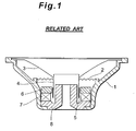
- Fig. 1 is a sectional view illustrating the structure of a conventional speaker.
- a damper 2 is interposed between a frame 1 and a voice coil bobbin 4.
- the voice coil bobbin 4 is coupled to a diaphragm 3 and supported by the damper 2 in such a manner as to permit it to vibrate in the axis direction.
- a portion of the voice coil bobbin 4 around which a voice coil 5 is wound is inserted into a magnetic gap between a yoke 8 and a plate 6 and magnet 7 which form a magnetic circuit.
- the magnetic circuit gives rise to the vibrations of the voice coil bobbin 4 and the diaphragm 3 in the axis direction.
- the conventional speaker has the yoke 8 coupled to a part of the bottomportion of the frame 1 in order to support the magnetic circuit.
- the speaker of the structure as described above may possibly produce dissonance because when the speaker is driven, the magnetic circuit reacts to the vibrations of the voice coil bobbin 4 and the diaphragm 3, whereupon the vibration is transmitted from the yoke 8 to the frame 1, and then from the frame 1 to portion of the speaker-mounted structure.
- An object of the present invention is to solve the problem associated with the conventional speakers as described above.
- the present invention provides a speaker having a magnetic circuit causing vibrations of a diaphragm and attached to and supported on a speaker frame, which is characterized by comprising a plurality of projections that are formed on a portion of the speaker frame supporting the magnetic circuit and are in contact with a component partially forming the magnetic circuit in order for the magnetic circuit to be supported on the speaker frame.
- the speaker comprises a magnetic circuit that is constituted of a yoke, a magnet and a plate and supported in a predetermined position in the frame by point contact between the rear face of the yoke and the plurality of projections formed on the inner face of the bottom portion of the frame that supports the diaphragm.
- a plurality of projections is formed on the inner face of the bottom portion of the frame, and in point contact with the rear face of the yoke to thereby support the magnetic circuit.
- this effects a reduction in the vibrations transmitted from the yoke to the frame due to the reaction of the magnetic circuit to the vibrations of the diaphragm when the speaker is driven.
- the problem associated with conventional speakers of dissonance being produced by transmission of the vibrations from the frame to a portion of the speaker-mounted structure is solved.
- Fig. 2 illustrates an embodiment of a speaker according to the present invention.
- a speaker 10 has a damper 13 interposed between a frame 11 and a voice coil bobbin 12.
- the damper 13 supports the voice coil bobbin 12 in such a way as to permit the voice coil bobbin 12 to vibrate in the axis direction.
- a voice coil 14 is wound around the outer periphery of a rear portion (a lower portion in Fig. 2) of the voice coil bobbin 12.
- a magnetic circuit of the speaker 10 is constituted of a yoke 15, a ring-shaped magnet 16 and a ring-shaped plate 17.
- the yoke 15 has a flange 15B formed integrally on the outer periphery of a rear end (a lower end in Fig. 2) of a cylinder 15A.
- the magnet 16 is supported on the flange 15B while its central portion is fitted around the cylinder 15A of the yoke 15 in a manner as described later.
- the plate 17 is securely positioned on the magnet 16 while its central portion is similarly fitted around the cylinder 15A of the yoke 15.
- a magnetic gap g of a required width is formed between the outer periphery of the cylinder 15A of the yoke 15 and the inner periphery of the plate 17.
- a portion of the voice coil bobbin 12 around which the voice coil 14 is wound is inserted into the magnetic gap g .
- the magnetic circuit causes vibration of the voice coil bobbin 12 in the axis direction (the up-down direction in Fig. 2).
- a diaphragm 18 is coupled to a portion of the voice coil bobbin 12 which is positioned closer to the leading end (the upper end in Fig. 2) of the voice coil bobbin 12 than the portion to which the damper 13 is coupled is positioned.
- the outer periphery portion of the diaphragm 18 is supported, via an edge 19, by the outer periphery portion of the frame 11 in such a manner as to permit the diaphragm 18 to vibrate.
- Fig. 3 is an enlarged view of the part of the frame 11 supporting the magnetic circuit.
- Fig. 4 is a plan view of the frame 11.
- a plurality of projections 11Aa are formed on the front-side face of a bottom portion 11A of the frame 11 which supports the magnetic circuit.
- the projections 11Aa are placed in contact with the rear-side face (the lower face in Figs. 2 and 3) of the flange 15B of the yoke 15. In this way the magnetic circuit is supported on the frame 11.
- the projections 11Aa can be formed in various shapes, such as a circular cone shape as shown in Fig. 5 or a hemispherical shape as shown in Fig. 6. Whatever the case, the projection 11Aa is shaped so that the leading end comes into point contact at with the flange 15B of the yoke 15.
- the projections 11Aa are projected inward (upward in Fig. 3) through the inner surface of the bottom portion 11A of the frame 11.
- the frame 11 when the frame 11 is formed of a metal-made plate material, a pressing process can be used to form the projections 11Aa.
- the magnetic circuit is supported on the frame 11 by means of point contact with the plurality of projections 11Aa which are formed on the bottom portion 11A of the frame 11.
- this effects a reduction in the vibration transmitted from the yoke 15 to the frame 11 by the reaction of the magnetic circuit to the vibrations of the voice coil bobbin 12 and the diaphragm 18 when the speaker is driven.
- the structure for preventing transmission of the vibration from the magnetic circuit to the frame 11 as described above is achieved merely through the process of forming the frame 11 without an increase in the number of components in the conventional speaker. Consequently, no increase in the manufacturing costs of the products is possible.
Landscapes
- Physics & Mathematics (AREA)
- Engineering & Computer Science (AREA)
- Acoustics & Sound (AREA)
- Signal Processing (AREA)
- Audible-Bandwidth Dynamoelectric Transducers Other Than Pickups (AREA)
Abstract
Description
Claims (6)
- A speaker having a magnetic circuit causing vibrations of a diaphragm (18) and attached to and supported on a speaker frame (11), characterized by comprising,
a plurality of projections (11Aa) formed on a portion of the speaker frame (11) supporting the magnetic circuit, and
in that the projections (11Aa) are in contact with a component (15) partially forming the magnetic circuit in order for the magnetic circuit to be supported on the speaker frame (11). - A speaker according to claim 1, wherein the projections (11Aa) are in point contact with the component (15) partially forming the magnetic circuit.
- A speaker according to claim 2, wherein each of the projections (11Aa) has a circular cone shape.
- A speaker according to claim 2, wherein each of the projections (11Aa) has a hemispherical shape.
- A speaker according to claim 1, wherein the magnet circuit is constituted of a yoke (15), a magnet (16) and a plate (17), and the projections (11Aa) are formed on a front-facing face of a bottom portion of the speaker frame (11) and in contact with a rear-facing face of the yoke (15) in order for the magnetic circuit to be supported on the speaker frame (11).
- A speaker according to claim 1, wherein the projections (11Aa) are formed by performing a pressing process on the speaker frame (11) .
Applications Claiming Priority (2)
| Application Number | Priority Date | Filing Date | Title |
|---|---|---|---|
| JP2004085061 | 2004-03-23 | ||
| JP2004085061A JP4408731B2 (en) | 2004-03-23 | 2004-03-23 | Speaker |
Publications (2)
| Publication Number | Publication Date |
|---|---|
| EP1581027A2 true EP1581027A2 (en) | 2005-09-28 |
| EP1581027A3 EP1581027A3 (en) | 2008-01-23 |
Family
ID=34858406
Family Applications (1)
| Application Number | Title | Priority Date | Filing Date |
|---|---|---|---|
| EP05006421A Withdrawn EP1581027A3 (en) | 2004-03-23 | 2005-03-23 | Speaker |
Country Status (3)
| Country | Link |
|---|---|
| US (1) | US7570779B2 (en) |
| EP (1) | EP1581027A3 (en) |
| JP (1) | JP4408731B2 (en) |
Families Citing this family (7)
| Publication number | Priority date | Publication date | Assignee | Title |
|---|---|---|---|---|
| USD346878S (en) * | 1991-03-25 | 1994-05-10 | Philip Morris Incorporated | Electrical cigarette |
| JP4790452B2 (en) | 2006-03-09 | 2011-10-12 | パイオニア株式会社 | Voice coil bobbin and speaker device |
| WO2008004272A1 (en) * | 2006-07-03 | 2008-01-10 | Pioneer Corporation | Speaker device and speaker unit |
| US8452040B2 (en) * | 2009-06-30 | 2013-05-28 | Srdjan Perovic | Speaker-transducer with integral bass-reflex and maximum efficiency cooling |
| KR101186727B1 (en) * | 2010-04-20 | 2012-09-28 | 허동철 | Speaker |
| USD884683S1 (en) * | 2019-01-02 | 2020-05-19 | Alpine Electronics, Inc. | Speaker driver frame |
| US11968512B2 (en) | 2022-06-22 | 2024-04-23 | Hewlett-Packard Development Company, L.P. | Speaker devices with dual-transducers |
Family Cites Families (9)
| Publication number | Priority date | Publication date | Assignee | Title |
|---|---|---|---|---|
| GB801695A (en) | 1956-02-16 | 1958-09-17 | Rola Celestion Ltd | Improvements in or relating to moving coil loudspeakers and microphones |
| DE9113037U1 (en) * | 1991-10-19 | 1992-01-09 | Nokia Unterhaltungselektronik (Deutschland) GmbH, 7530 Pforzheim | Cone speaker |
| JP3007469B2 (en) * | 1992-01-30 | 2000-02-07 | 東北パイオニア株式会社 | Speaker magnetic circuit |
| DE9301425U1 (en) | 1993-02-02 | 1993-05-06 | Wei, Kuang-Ta, Keelung | Floor support |
| JP3177758B2 (en) * | 1993-04-07 | 2001-06-18 | ミネベア株式会社 | Speaker and method of manufacturing the same |
| JP3748637B2 (en) | 1996-10-14 | 2006-02-22 | 松下電器産業株式会社 | Vibration generator for portable devices |
| JP3035704B1 (en) * | 1998-10-28 | 2000-04-24 | 株式会社アクーヴ・ラボ | Electro-mechanical vibration transducer |
| JP4075728B2 (en) | 2003-08-07 | 2008-04-16 | 松下電器産業株式会社 | Speaker |
| JP4362400B2 (en) * | 2004-03-25 | 2009-11-11 | パイオニア株式会社 | Speaker device and method for manufacturing speaker device |
-
2004
- 2004-03-23 JP JP2004085061A patent/JP4408731B2/en not_active Expired - Fee Related
-
2005
- 2005-03-22 US US11/085,180 patent/US7570779B2/en not_active Expired - Fee Related
- 2005-03-23 EP EP05006421A patent/EP1581027A3/en not_active Withdrawn
Also Published As
| Publication number | Publication date |
|---|---|
| JP4408731B2 (en) | 2010-02-03 |
| EP1581027A3 (en) | 2008-01-23 |
| US7570779B2 (en) | 2009-08-04 |
| JP2005277561A (en) | 2005-10-06 |
| US20050226458A1 (en) | 2005-10-13 |
Similar Documents
| Publication | Publication Date | Title |
|---|---|---|
| US9185494B2 (en) | Inner magnet type microspeaker | |
| US8041070B2 (en) | Speaker | |
| US7221773B2 (en) | Oval speaker apparatus and method of manufacturing the same | |
| EP1467594A2 (en) | Loudspeaker | |
| US20110135111A1 (en) | Speaker device and automobile | |
| US7570779B2 (en) | Speaker | |
| CN101583067A (en) | Electroacoustic transducing device | |
| JP2011166722A (en) | Loudspeaker | |
| JP4594858B2 (en) | Speaker | |
| JP2009159009A (en) | Speaker | |
| EP1804551B1 (en) | Speaker | |
| US20200336838A1 (en) | Speaker Unit | |
| JP2012044575A (en) | Electrodynamic speaker, manufacturing jig therefor, and manufacturing method therefor | |
| JP4264579B2 (en) | Speaker device | |
| JP2005269328A (en) | Loudspeaker apparatus | |
| US20100158305A1 (en) | Loudspeaker | |
| JP2006100879A (en) | Ring type speaker | |
| JP2013138375A (en) | Speaker device | |
| KR102434194B1 (en) | The speaker | |
| KR101481650B1 (en) | Microspeaker with improved vibration module | |
| JP4245463B2 (en) | Speaker device | |
| US20060093182A1 (en) | Speaker | |
| KR200351435Y1 (en) | Compact speaker unit | |
| JP2005269327A (en) | Loudspeaker apparatus and manufacturing method thereof | |
| JP2009010512A (en) | Dynamic micro-speaker and manufacturing method thereof |
Legal Events
| Date | Code | Title | Description |
|---|---|---|---|
| PUAI | Public reference made under article 153(3) epc to a published international application that has entered the european phase |
Free format text: ORIGINAL CODE: 0009012 |
|
| AK | Designated contracting states |
Kind code of ref document: A2 Designated state(s): AT BE BG CH CY CZ DE DK EE ES FI FR GB GR HU IE IS IT LI LT LU MC NL PL PT RO SE SI SK TR |
|
| AX | Request for extension of the european patent |
Extension state: AL BA HR LV MK YU |
|
| PUAL | Search report despatched |
Free format text: ORIGINAL CODE: 0009013 |
|
| AK | Designated contracting states |
Kind code of ref document: A3 Designated state(s): AT BE BG CH CY CZ DE DK EE ES FI FR GB GR HU IE IS IT LI LT LU MC NL PL PT RO SE SI SK TR |
|
| AX | Request for extension of the european patent |
Extension state: AL BA HR LV MK YU |
|
| STAA | Information on the status of an ep patent application or granted ep patent |
Free format text: STATUS: THE APPLICATION HAS BEEN WITHDRAWN |
|
| 18W | Application withdrawn |
Effective date: 20080328 |
|
| P01 | Opt-out of the competence of the unified patent court (upc) registered |
Effective date: 20230428 |