EP1580887A1 - Système de commande de vitesse d'un moteur de groupe moto-ventilateur, notamment pour une installation de chauffage et/ou de climatisation de véhicule automobile - Google Patents
Système de commande de vitesse d'un moteur de groupe moto-ventilateur, notamment pour une installation de chauffage et/ou de climatisation de véhicule automobile Download PDFInfo
- Publication number
- EP1580887A1 EP1580887A1 EP05001261A EP05001261A EP1580887A1 EP 1580887 A1 EP1580887 A1 EP 1580887A1 EP 05001261 A EP05001261 A EP 05001261A EP 05001261 A EP05001261 A EP 05001261A EP 1580887 A1 EP1580887 A1 EP 1580887A1
- Authority
- EP
- European Patent Office
- Prior art keywords
- effect transistor
- field effect
- motor
- source
- circuit
- Prior art date
- Legal status (The legal status is an assumption and is not a legal conclusion. Google has not performed a legal analysis and makes no representation as to the accuracy of the status listed.)
- Granted
Links
Images

Classifications
-
- H—ELECTRICITY
- H02—GENERATION; CONVERSION OR DISTRIBUTION OF ELECTRIC POWER
- H02P—CONTROL OR REGULATION OF ELECTRIC MOTORS, ELECTRIC GENERATORS OR DYNAMO-ELECTRIC CONVERTERS; CONTROLLING TRANSFORMERS, REACTORS OR CHOKE COILS
- H02P7/00—Arrangements for regulating or controlling the speed or torque of electric DC motors
- H02P7/06—Arrangements for regulating or controlling the speed or torque of electric DC motors for regulating or controlling an individual DC dynamo-electric motor by varying field or armature current
- H02P7/18—Arrangements for regulating or controlling the speed or torque of electric DC motors for regulating or controlling an individual DC dynamo-electric motor by varying field or armature current by master control with auxiliary power
- H02P7/24—Arrangements for regulating or controlling the speed or torque of electric DC motors for regulating or controlling an individual DC dynamo-electric motor by varying field or armature current by master control with auxiliary power using discharge tubes or semiconductor devices
- H02P7/28—Arrangements for regulating or controlling the speed or torque of electric DC motors for regulating or controlling an individual DC dynamo-electric motor by varying field or armature current by master control with auxiliary power using discharge tubes or semiconductor devices using semiconductor devices
- H02P7/285—Arrangements for regulating or controlling the speed or torque of electric DC motors for regulating or controlling an individual DC dynamo-electric motor by varying field or armature current by master control with auxiliary power using discharge tubes or semiconductor devices using semiconductor devices controlling armature supply only
- H02P7/29—Arrangements for regulating or controlling the speed or torque of electric DC motors for regulating or controlling an individual DC dynamo-electric motor by varying field or armature current by master control with auxiliary power using discharge tubes or semiconductor devices using semiconductor devices controlling armature supply only using pulse modulation
Definitions
- the invention relates to a speed control system of a fan motor motor.
- the field of application is in particular that of heating and / or air conditioning particularly for motor vehicles.
- a group motor-fan of the type comprising a volute casing, a turbine housed in the casing of volute to generate a flow of air in it, a drive motor of the turbine, and a control module of the engine with a control system to vary the engine speed as required.
- the engine speed control system motor-fan unit comprises a field effect transistor of the type MOS, operating in PWM pulse width modulation.
- pulse width modulation generates rapid changes in voltage and current causing disturbances electromagnetic so called EMC.
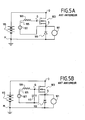
- Figures 5A and 5B show two conventional examples of speed control systems of an engine 101 having a field effect transistor 103.
- FIG. 5A shows that a circuit 105, comprising in series a voltage source 107 of value V and a resistance resistor element 109 Rg, is connected between the gate G and the source S of the field effect transistor 103.
- a power source 115 is connected to the drain D of the field effect transistor 103 and to a motor terminal 101.
- the other terminal of the motor 101 is connected to the source S of the field 103.
- a freewheel circuit 113 is connected across the terminals of the engine 101.
- the intrinsic capacitance Cgs varies from component to component because of the manufacturing tolerance of these components. This capacitance variability from one transistor to another causes differences in the level of electromagnetic interference from one product to another. This is not acceptable for a car manufacturer.
- FIG. 5B shows a control system similar to that of FIG. 5A but in which capacitor 117 of capacitance Cgk is added between gate G and source S of field effect transistor 103.
- the decrease in the current slope is controlled by an increase in the capacitance Cgk.
- the variation of the intrinsic capacitance Cgs from one component to another always results in a large variability of the current slope, thus causing a great dispersion of the level of electromagnetic disturbance from one product to another.
- the object of the invention is to provide a control system of speed of an engine with low electromagnetic disturbances.
- a speed control system a motor-fan motor unit having an effect transistor of field controlling the motor by width modulation pulse, the field effect transistor being connected to a circuit comprising in series a voltage source and a resistive element, characterized in that said circuit is connected between the gate of the transistor field effect and a second source connected to a first source of the field effect transistor via an inductor for allow a decrease in the slope of the current when switching of the field effect transistor.
- the inductance makes it possible at the same time to reduce the slope of the current and make negligible the impact of the intrinsic capacity of the field effect transistor on the slope of the current thus decreasing strongly electromagnetic disturbances.
- the system comprises a circuit of freewheel connected between the ground and the second source of the field, the drain of said transistor being connected to a power source.
- the system comprises a circuit of free wheel connected between a power source and the drain of the transistor field effect, the second source of said transistor being connected to ground.
- the motor is connected to the terminals of the circuit to freewheel.
- the value of the inductance is between 5nH and 30nH.
- the inductance is achieved by card routing printed circuit between the first source and the second source of the field effect transistor.
- the length of the track from the map routing to printed circuit board may be between 5 mm and 30 mm.
- the inductance can be created by an electronic component.
- the electronic component can be a current measurement shunt.
- the system comprises a connected capacitor between the gate and the second source of the field effect transistor.
- the field effect transistor may be MOS type.
- the invention also relates to a control module of a group motor-fan and a heating and / or air conditioning system for a motor vehicle having a control system of speed as above.
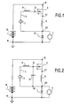
- Figure 1 shows very schematically a system of speed control of a motor 1 fan motor unit having a field effect transistor 3 controlling the motor 1 by pulse width modulation.
- the field effect transistor 3 for example of the MOS type, is connected to a circuit 5 comprising in series a voltage source 7 of value V and a resistive element 9 of a resistor Rg.
- This circuit 5 is connected between the gate G of the field effect transistor 3 and a second source S2 connected to a first source S1 of the field effect transistor 3 via an inductance 11 of value L.
- a power source 15 is connected to the drain D of the transistor field effect 3 and one motor terminal 1.
- the other motor terminal 1 is connected to the second source S2 of the field effect transistor 3.
- the control system further comprises a wheel circuit 13 connected between the mass M and the second source S2 of the transistor field effect 3, so that the motor 1 is connected to the terminals of this freewheel circuit 13.
- the freewheel circuit 13 comprises, for example a diode or other field effect transistor playing the role of a diode.
- the field effect transistor 3 operates in commutation, saturated / blocked. Thus, when the transistor 3 is saturated, the current delivered by the power source 15 passes through the transistor effect of field 3 and the engine 1.
- the slope P of the current during the switching of the field effect transistor 3 depends on the resistance Rg, an intrinsic capacitance Cgs of the field effect transistor 3, the value of the inductance L affected by a parameter s defining the transconductance of the field effect transistor 3 and a calculation constant k .
- the slope P depends on an additional parameter which makes it possible on the one hand to act on this slope and on the other hand to reduce the impact of the capacitance Cgs.
- the inductance L makes it possible to reduce the slope of the current during the switching of the field effect transistor 3.
- the value of the inductance L makes negligible the impact of the intrinsic capacitance Cgs of the field effect transistor 3 on the slope of the current further decreasing the electromagnetic disturbances, and consequently the electromagnetic field one module to another.
- Another advantage is the fact that for the same slope, it is possible to increase the value of the inductance L and to decrease the resistance Rg , thereby reducing the energy dissipation by the latter during the switching of the effect transistor. field 3.
- a small inductance value is sufficient to significantly reduce disturbances electromagnetic.
- the inductor 11 can be realized by a card routing circuit board, that is to say a conductive track advantageously in copper made on the printed circuit board, between the first source S1 and the second source S2 of the field effect transistor 3.
- a routing between about 5mm to 30mm generates an inductance whose order is between 5nH and 30nH which is enough to reduce disturbances electromagnetically noticeable.
- the inductor 11 can be created by the inductor parasite of an electronic component that is already part of the engine control.
- the electronic component can be a shunt of low resistance which by means of a comparator makes it possible to measure the current in the motor.
- FIG. 2 is another embodiment that differs from FIG. 1 in that it comprises a capacitor 17, with a capacitance Cgk, connected between the gate G and the second source S2 of the field effect transistor 3.
- the first-order slope P of the current when the field-effect transistor 3 is switched depends on the resistance Rg, the capacitance Cgk, the value of the inductance L and a calculation constant. k.
- the capacitance Cgk in addition to the value of the inductance L makes it possible to decrease appropriately the slope of the current during the switching of the field effect transistor 3.
- the slope P does not depend on the intrinsic capacitance Cgs, thus eliminating any impact of this intrinsic capacitance Cgs of the field effect transistor 3 on the slope of the current.
- the circuit freewheel 13 is connected between the power source 15 and the drain D of the field effect transistor 3.
- the second source S2 of the field effect transistor 3 is connected to ground M. It is understood here that the invention is applicable as much to a circuit called “high side” as to a circuit called “low side”, that is to say when the transistor is between a terminal of the engine and the mass.
- FIG. 4 is yet another embodiment which differs from FIG. 3 in that it comprises a capacitor 17 with a capacitance Cgk connected between the gate G and the second source S2 of the field effect transistor 3.
- the speed control system thus designed can therefore be easily incorporated into a standard control module of a motor-fan unit for a heating and / or air conditioning for a motor vehicle.
Landscapes
- Engineering & Computer Science (AREA)
- Power Engineering (AREA)
- Control Of Direct Current Motors (AREA)
Abstract
Description
- la figure 1 est une vue très schématique d'un système de commande de vitesse d'un moteur de groupe moto-ventilateur comportant un transistor à effet de champ commandant le moteur par une modulation de largeur d'impulsion, selon l'invention,
- la figure 2 est un autre mode de réalisation qui se distingue de la figure 1 en ce qu'il comporte un condensateur,
- la figure 3 est une variante de la figure 1,
- la figure 4 est un autre mode de réalisation qui se distingue de la figure 3 en ce qu'il comporte un condensateur, et
- les figures 5A et 5B sont des vues très schématiques de systèmes de commande de vitesse d'un moteur selon l'art antérieur.
Claims (13)
- Système de commande de vitesse d'un moteur (1) de groupe moto-ventilateur comportant un transistor à effet de champ (3) commandant le moteur (1) par une modulation de largeur d'impulsion, le transistor à effet de champ (3) étant relié à un circuit (5) comprenant en série une source de tension (7) et un élément résistif (9), caractérisé en ce que ledit circuit (5) est connecté entre la grille (G) du transistor à effet de champ (3) et une seconde source (S2) reliée à une première source (S1) du transistor à effet de champ (3) par l'intermédiaire d'une inductance (11) pour permettre une diminution de la pente du courant lors de la commutation du transistor à effet de champ (3).
- Système selon la revendication 1, caractérisé en ce qu'il comporte en outre un circuit de roue libre (13) relié entre la masse (M) et la seconde source (S2) du transistor à effet de champ (3), le drain (D) dudit transistor à effet de champ (3) étant relié à une source d'alimentation (15).
- Système selon la revendication 1, caractérisé en ce qu'il comporte en outre un circuit de roue libre (13) relié entre une source d'alimentation (15) et le drain (D) du transistor à effet de champ (3), la seconde source (S2) dudit transistor à effet de champ (3) étant reliée à la masse (M).
- Système selon l'une quelconque des revendications 2 et 3, caractérisé en ce que le moteur (1) est relié aux bornes du circuit à roue libre (13).
- Système selon l'une quelconque des revendications 1 à 4, caractérisé en ce que la valeur de l'inductance (11) est comprise entre 5nH et 30nH.
- Système selon l'une quelconque des revendications 1 à 5, caractérisé en ce que l'inductance (11) est réalisée par un routage de carte de circuit imprimé entre la première source (S1) et la seconde source (S2) du transistor à effet de champ (3).
- Système selon la revendication 6, caractérisé en ce que la longueur de la piste du routage de carte à circuit imprimé est comprise entre 5 mm et 30 mm.
- Système selon l'une quelconque des revendications 1 à 5, caractérisé en ce que l'inductance (11) est créée par un composant électronique.
- Système selon la revendication 8, caractérisé en ce que le composant électronique est un shunt de mesure du courant.
- Système selon l'une quelconque des revendications 1 à 9, caractérisé en ce qu'il comporte en outre un condensateur (17) relié entre la grille (G) et la seconde source (S2) du transistor à effet de champ (3).
- Système selon l'une quelconque des revendications 1 à 10, caractérisé en ce que le transistor à effet de champ (3) est du type MOS.
- Module de commande d'un groupe moto-ventilateur, muni d'un système de commande de vitesse selon l'une quelconque des revendications 1 à 11.
- Installation de chauffage et/ou climatisation pour véhicule automobile, comportant un groupe moto-ventilateur muni d'un module de commande selon la revendication 12.
Applications Claiming Priority (2)
| Application Number | Priority Date | Filing Date | Title |
|---|---|---|---|
| FR0402329 | 2004-03-05 | ||
| FR0402329A FR2867323B1 (fr) | 2004-03-05 | 2004-03-05 | Systeme de commande de vitesse d'un moteur de groupe moto-ventilateur, notamment pour une installation de chauffage et/ou de climatisation de vehicule automobile |
Publications (2)
| Publication Number | Publication Date |
|---|---|
| EP1580887A1 true EP1580887A1 (fr) | 2005-09-28 |
| EP1580887B1 EP1580887B1 (fr) | 2018-08-01 |
Family
ID=34855086
Family Applications (1)
| Application Number | Title | Priority Date | Filing Date |
|---|---|---|---|
| EP05001261.6A Expired - Lifetime EP1580887B1 (fr) | 2004-03-05 | 2005-01-21 | Système de commande de vitesse d'un moteur de groupe moto-ventilateur, notamment pour une installation de chauffage et/ou de climatisation de véhicule automobile |
Country Status (3)
| Country | Link |
|---|---|
| US (1) | US7061201B2 (fr) |
| EP (1) | EP1580887B1 (fr) |
| FR (1) | FR2867323B1 (fr) |
Cited By (1)
| Publication number | Priority date | Publication date | Assignee | Title |
|---|---|---|---|---|
| WO2010083827A3 (fr) * | 2009-01-26 | 2011-03-10 | Bergmann Messgeräte Entwicklung Kg | Commutateur haute tension à courant réglable |
Families Citing this family (4)
| Publication number | Priority date | Publication date | Assignee | Title |
|---|---|---|---|---|
| FR2942324B1 (fr) * | 2009-02-16 | 2011-05-20 | Valeo Systemes Thermiques | Procede de detection d'un court-circuit et module d'alimentation mettant en oeuvre ce procede |
| GB2493562B (en) * | 2011-08-12 | 2018-10-17 | E2V Tech Uk Limited | Drive circuit and method for a gated semiconductor switching device |
| US10892591B2 (en) | 2018-04-03 | 2021-01-12 | Fermi Research Alliance, Llc | High speed driver for particle beam deflector |
| FR3086496A1 (fr) * | 2018-09-25 | 2020-03-27 | Valeo Systemes Thermiques | Calculateur de commande d'un groupe moto-ventilateur d'un vehicule automobile |
Citations (6)
| Publication number | Priority date | Publication date | Assignee | Title |
|---|---|---|---|---|
| EP0250036A1 (fr) * | 1986-06-17 | 1987-12-23 | Koninklijke Philips Electronics N.V. | Circuit intégré logique comportant un circuit de sortie pour la génération d'un courant de sortie dont l'évolution est limitée dans le temps |
| EP0493185A1 (fr) * | 1990-12-27 | 1992-07-01 | Automobiles Peugeot | Circuit de commande d'un transistor de puissance utilisé en commutation forcée |
| DE4429733A1 (de) * | 1993-08-26 | 1995-03-02 | Mitsubishi Electric Corp | Leistungsschaltvorrichtung |
| EP0687056A2 (fr) * | 1994-06-06 | 1995-12-13 | Kabushiki Kaisha Toshiba | Circuit de contrÔle de grille pour un dispositif de commutation de puissance |
| US5811948A (en) * | 1995-08-02 | 1998-09-22 | Nippondenso Co., Ltd. | Control apparatus for electric motor |
| US20040100150A1 (en) * | 2002-11-26 | 2004-05-27 | Stephan Bolz | Circuit arrangement for high-speed switching of inductive loads |
Family Cites Families (13)
| Publication number | Priority date | Publication date | Assignee | Title |
|---|---|---|---|---|
| US3971972A (en) * | 1975-03-14 | 1976-07-27 | Allis-Chalmers Corporation | Transistor inverter motor drive having voltage boost at low speeds |
| US4329630A (en) * | 1980-01-04 | 1982-05-11 | General Electric Company | Single transistor power control circuit for a DC motor washing machine drive |
| US4556827A (en) * | 1980-04-17 | 1985-12-03 | General Electric Company | Laundering apparatus, method of operating a laundry machine, control system for an electronically commutated motor, method of operating an electronically commutated motor, and circuit |
| US4673851A (en) * | 1986-03-31 | 1987-06-16 | General Motors Corporation | PWM motor operating system with RFI suppression |
| US5180964A (en) * | 1990-03-28 | 1993-01-19 | Ewing Gerald D | Zero-voltage switched FM-PWM converter |
| US5446366A (en) * | 1994-02-08 | 1995-08-29 | Computer Products, Inc. | Boost converter power supply with reduced losses, control circuit and method therefor |
| US5552976A (en) * | 1994-06-10 | 1996-09-03 | Northrop Grumman Corporation | EMI filter topology for power inverters |
| US5742142A (en) * | 1996-08-09 | 1998-04-21 | Delco Electronics Corp. | Low radiated emission motor speed control with PWM regulator |
| US6166500A (en) * | 1997-07-18 | 2000-12-26 | Siemens Canada Limited | Actively controlled regenerative snubber for unipolar brushless DC motors |
| WO2000064040A1 (fr) * | 1999-04-15 | 2000-10-26 | Nagares, S.A. | Regulateur de vitesse par modulation de la largeur des impulsions pour moteurs a courant continu |
| WO2002019510A1 (fr) * | 2000-08-30 | 2002-03-07 | Papst-Motoren Gmbh & Co. Kg | Generatrice a courant continu avec dispositif de limitation de courant regulable |
| US6459324B1 (en) * | 2000-10-23 | 2002-10-01 | International Rectifier Corporation | Gate drive circuit with feedback-controlled active resistance |
| JP2004152995A (ja) * | 2002-10-30 | 2004-05-27 | Toshiba Corp | 半導体装置の製造方法 |
-
2004
- 2004-03-05 FR FR0402329A patent/FR2867323B1/fr not_active Expired - Fee Related
-
2005
- 2005-01-21 EP EP05001261.6A patent/EP1580887B1/fr not_active Expired - Lifetime
- 2005-03-04 US US11/072,770 patent/US7061201B2/en not_active Expired - Lifetime
Patent Citations (6)
| Publication number | Priority date | Publication date | Assignee | Title |
|---|---|---|---|---|
| EP0250036A1 (fr) * | 1986-06-17 | 1987-12-23 | Koninklijke Philips Electronics N.V. | Circuit intégré logique comportant un circuit de sortie pour la génération d'un courant de sortie dont l'évolution est limitée dans le temps |
| EP0493185A1 (fr) * | 1990-12-27 | 1992-07-01 | Automobiles Peugeot | Circuit de commande d'un transistor de puissance utilisé en commutation forcée |
| DE4429733A1 (de) * | 1993-08-26 | 1995-03-02 | Mitsubishi Electric Corp | Leistungsschaltvorrichtung |
| EP0687056A2 (fr) * | 1994-06-06 | 1995-12-13 | Kabushiki Kaisha Toshiba | Circuit de contrÔle de grille pour un dispositif de commutation de puissance |
| US5811948A (en) * | 1995-08-02 | 1998-09-22 | Nippondenso Co., Ltd. | Control apparatus for electric motor |
| US20040100150A1 (en) * | 2002-11-26 | 2004-05-27 | Stephan Bolz | Circuit arrangement for high-speed switching of inductive loads |
Cited By (1)
| Publication number | Priority date | Publication date | Assignee | Title |
|---|---|---|---|---|
| WO2010083827A3 (fr) * | 2009-01-26 | 2011-03-10 | Bergmann Messgeräte Entwicklung Kg | Commutateur haute tension à courant réglable |
Also Published As
| Publication number | Publication date |
|---|---|
| FR2867323A1 (fr) | 2005-09-09 |
| US7061201B2 (en) | 2006-06-13 |
| EP1580887B1 (fr) | 2018-08-01 |
| US20050194919A1 (en) | 2005-09-08 |
| FR2867323B1 (fr) | 2006-10-20 |
Similar Documents
| Publication | Publication Date | Title |
|---|---|---|
| EP1676140B1 (fr) | Dispositif de mesure non dissipatif du courant dans une inductance | |
| EP2719070B1 (fr) | Procede de controle d'un couple resistant d'un alternateur de vehicule automobile, et systeme de mise en oeuvre de ce procede | |
| WO2013117500A2 (fr) | Systeme et procede de commande de l'alimentation d'une machine electrique en fonction de la temperature | |
| EP1580887B1 (fr) | Système de commande de vitesse d'un moteur de groupe moto-ventilateur, notamment pour une installation de chauffage et/ou de climatisation de véhicule automobile | |
| EP0782265B1 (fr) | Procédé et dispositif pour la protection d'un élément à impédance réglable commandant l'alimentation d'un moteur électrique, notamment de véhicule automobile | |
| EP1119097A1 (fr) | Moteur triphasé à vitesse variable et commutation électronique | |
| CA2326641C (fr) | Redresseur synchrone auto-commande | |
| EP1992069B1 (fr) | Dispositif de commande d'un transistor mos | |
| EP2538538A1 (fr) | Carte de circuit imprimé pour boîtier de compresseur | |
| FR2634916A1 (fr) | Circuit de commande de variation de puissance avec plusieurs transistors de puissance en parallele | |
| FR2998116A1 (fr) | Circuit de mesure pour reguler un transformateur de tension continue | |
| EP1176287B1 (fr) | Dispositif de pilotage des actionneurs de soupapes d'un moteur à combustion interne à courant d'alimentation stabilisé | |
| FR2819656A1 (fr) | Limiteur de tension pour circuit interface d'un bus de communication | |
| FR3155356A1 (fr) | Dispositif de regulation du courant electrique fourni a un ensemble de contacteurs | |
| EP3794700B1 (fr) | Circuit de protection d'un interrupteur | |
| EP1096656A1 (fr) | Moteur, et sa commande, pour le déplacement d'un volet d'une installation de ventilation, chauffage et/ou climatisation d'un véhicule automobile | |
| FR2916278A1 (fr) | Procede de gestion d'un circuit d'une electrovanne d'un systeme de freinage electronique | |
| EP3646426B1 (fr) | Procede de protection des composants d'un module electronique de puissance d'un systeme a alterno-demarreur et systeme mettant en oeuvre ce procede | |
| FR2832509A1 (fr) | Detecteur de surcharge pour convertisseur de tension continue, composant et dispositif correspondants | |
| EP0499503A1 (fr) | Circuit de commande et de régulation pour moteur électrique à commutation électronique | |
| WO2005011100A2 (fr) | Système de contrôle de vitesse d'un moteur de groupe moto-ventilateur | |
| FR2529402A1 (fr) | Montage de protection contre les surcharges d'un moteur a courant continu et a champ constant | |
| WO2004077077A1 (fr) | Procede pour mesurer l'intensite du courant consomme par un radiateur electrique d'un appareil de ventilation de chauffage et/ou de climatisation de vehicule | |
| CH717513A2 (fr) | Pilote de sortie commandé par vitesse de balayage. | |
| FR2942324A1 (fr) | Procede de detection d'un court-circuit et module d'alimentation mettant en oeuvre ce procede |
Legal Events
| Date | Code | Title | Description |
|---|---|---|---|
| PUAI | Public reference made under article 153(3) epc to a published international application that has entered the european phase |
Free format text: ORIGINAL CODE: 0009012 |
|
| AK | Designated contracting states |
Kind code of ref document: A1 Designated state(s): AT BE BG CH CY CZ DE DK EE ES FI FR GB GR HU IE IS IT LI LT LU MC NL PL PT RO SE SI SK TR |
|
| AX | Request for extension of the european patent |
Extension state: AL BA HR LV MK YU |
|
| 17P | Request for examination filed |
Effective date: 20060302 |
|
| AKX | Designation fees paid |
Designated state(s): AT BE BG CH CY CZ DE DK EE ES FI FR GB GR HU IE IS IT LI LT LU MC NL PL PT RO SE SI SK TR |
|
| 17Q | First examination report despatched |
Effective date: 20130620 |
|
| GRAP | Despatch of communication of intention to grant a patent |
Free format text: ORIGINAL CODE: EPIDOSNIGR1 |
|
| STAA | Information on the status of an ep patent application or granted ep patent |
Free format text: STATUS: GRANT OF PATENT IS INTENDED |
|
| INTG | Intention to grant announced |
Effective date: 20180320 |
|
| GRAS | Grant fee paid |
Free format text: ORIGINAL CODE: EPIDOSNIGR3 |
|
| GRAA | (expected) grant |
Free format text: ORIGINAL CODE: 0009210 |
|
| STAA | Information on the status of an ep patent application or granted ep patent |
Free format text: STATUS: THE PATENT HAS BEEN GRANTED |
|
| AK | Designated contracting states |
Kind code of ref document: B1 Designated state(s): AT BE BG CH CY CZ DE DK EE ES FI FR GB GR HU IE IS IT LI LT LU MC NL PL PT RO SE SI SK TR |
|
| REG | Reference to a national code |
Ref country code: GB Ref legal event code: FG4D Free format text: NOT ENGLISH |
|
| REG | Reference to a national code |
Ref country code: CH Ref legal event code: EP Ref country code: AT Ref legal event code: REF Ref document number: 1025537 Country of ref document: AT Kind code of ref document: T Effective date: 20180815 |
|
| REG | Reference to a national code |
Ref country code: IE Ref legal event code: FG4D Free format text: LANGUAGE OF EP DOCUMENT: FRENCH |
|
| REG | Reference to a national code |
Ref country code: DE Ref legal event code: R096 Ref document number: 602005054340 Country of ref document: DE |
|
| REG | Reference to a national code |
Ref country code: NL Ref legal event code: MP Effective date: 20180801 |
|
| REG | Reference to a national code |
Ref country code: LT Ref legal event code: MG4D |
|
| REG | Reference to a national code |
Ref country code: AT Ref legal event code: MK05 Ref document number: 1025537 Country of ref document: AT Kind code of ref document: T Effective date: 20180801 |
|
| PG25 | Lapsed in a contracting state [announced via postgrant information from national office to epo] |
Ref country code: NL Free format text: LAPSE BECAUSE OF FAILURE TO SUBMIT A TRANSLATION OF THE DESCRIPTION OR TO PAY THE FEE WITHIN THE PRESCRIBED TIME-LIMIT Effective date: 20180801 Ref country code: IS Free format text: LAPSE BECAUSE OF FAILURE TO SUBMIT A TRANSLATION OF THE DESCRIPTION OR TO PAY THE FEE WITHIN THE PRESCRIBED TIME-LIMIT Effective date: 20181201 Ref country code: AT Free format text: LAPSE BECAUSE OF FAILURE TO SUBMIT A TRANSLATION OF THE DESCRIPTION OR TO PAY THE FEE WITHIN THE PRESCRIBED TIME-LIMIT Effective date: 20180801 Ref country code: SE Free format text: LAPSE BECAUSE OF FAILURE TO SUBMIT A TRANSLATION OF THE DESCRIPTION OR TO PAY THE FEE WITHIN THE PRESCRIBED TIME-LIMIT Effective date: 20180801 Ref country code: BG Free format text: LAPSE BECAUSE OF FAILURE TO SUBMIT A TRANSLATION OF THE DESCRIPTION OR TO PAY THE FEE WITHIN THE PRESCRIBED TIME-LIMIT Effective date: 20181101 Ref country code: LT Free format text: LAPSE BECAUSE OF FAILURE TO SUBMIT A TRANSLATION OF THE DESCRIPTION OR TO PAY THE FEE WITHIN THE PRESCRIBED TIME-LIMIT Effective date: 20180801 Ref country code: PL Free format text: LAPSE BECAUSE OF FAILURE TO SUBMIT A TRANSLATION OF THE DESCRIPTION OR TO PAY THE FEE WITHIN THE PRESCRIBED TIME-LIMIT Effective date: 20180801 Ref country code: FI Free format text: LAPSE BECAUSE OF FAILURE TO SUBMIT A TRANSLATION OF THE DESCRIPTION OR TO PAY THE FEE WITHIN THE PRESCRIBED TIME-LIMIT Effective date: 20180801 Ref country code: GR Free format text: LAPSE BECAUSE OF FAILURE TO SUBMIT A TRANSLATION OF THE DESCRIPTION OR TO PAY THE FEE WITHIN THE PRESCRIBED TIME-LIMIT Effective date: 20181102 |
|
| REG | Reference to a national code |
Ref country code: CH Ref legal event code: PK Free format text: RECTIFICATIONS |
|
| RIC2 | Information provided on ipc code assigned after grant |
Ipc: H02P 7/29 20160101ALI20050708BHEP Ipc: H03K 17/16 20060101AFI20050708BHEP |
|
| PG25 | Lapsed in a contracting state [announced via postgrant information from national office to epo] |
Ref country code: ES Free format text: LAPSE BECAUSE OF FAILURE TO SUBMIT A TRANSLATION OF THE DESCRIPTION OR TO PAY THE FEE WITHIN THE PRESCRIBED TIME-LIMIT Effective date: 20180801 |
|
| PG25 | Lapsed in a contracting state [announced via postgrant information from national office to epo] |
Ref country code: CZ Free format text: LAPSE BECAUSE OF FAILURE TO SUBMIT A TRANSLATION OF THE DESCRIPTION OR TO PAY THE FEE WITHIN THE PRESCRIBED TIME-LIMIT Effective date: 20180801 Ref country code: RO Free format text: LAPSE BECAUSE OF FAILURE TO SUBMIT A TRANSLATION OF THE DESCRIPTION OR TO PAY THE FEE WITHIN THE PRESCRIBED TIME-LIMIT Effective date: 20180801 Ref country code: EE Free format text: LAPSE BECAUSE OF FAILURE TO SUBMIT A TRANSLATION OF THE DESCRIPTION OR TO PAY THE FEE WITHIN THE PRESCRIBED TIME-LIMIT Effective date: 20180801 Ref country code: IT Free format text: LAPSE BECAUSE OF FAILURE TO SUBMIT A TRANSLATION OF THE DESCRIPTION OR TO PAY THE FEE WITHIN THE PRESCRIBED TIME-LIMIT Effective date: 20180801 |
|
| REG | Reference to a national code |
Ref country code: DE Ref legal event code: R097 Ref document number: 602005054340 Country of ref document: DE |
|
| PG25 | Lapsed in a contracting state [announced via postgrant information from national office to epo] |
Ref country code: SK Free format text: LAPSE BECAUSE OF FAILURE TO SUBMIT A TRANSLATION OF THE DESCRIPTION OR TO PAY THE FEE WITHIN THE PRESCRIBED TIME-LIMIT Effective date: 20180801 Ref country code: DK Free format text: LAPSE BECAUSE OF FAILURE TO SUBMIT A TRANSLATION OF THE DESCRIPTION OR TO PAY THE FEE WITHIN THE PRESCRIBED TIME-LIMIT Effective date: 20180801 |
|
| PLBE | No opposition filed within time limit |
Free format text: ORIGINAL CODE: 0009261 |
|
| STAA | Information on the status of an ep patent application or granted ep patent |
Free format text: STATUS: NO OPPOSITION FILED WITHIN TIME LIMIT |
|
| 26N | No opposition filed |
Effective date: 20190503 |
|
| PG25 | Lapsed in a contracting state [announced via postgrant information from national office to epo] |
Ref country code: SI Free format text: LAPSE BECAUSE OF FAILURE TO SUBMIT A TRANSLATION OF THE DESCRIPTION OR TO PAY THE FEE WITHIN THE PRESCRIBED TIME-LIMIT Effective date: 20180801 Ref country code: MC Free format text: LAPSE BECAUSE OF FAILURE TO SUBMIT A TRANSLATION OF THE DESCRIPTION OR TO PAY THE FEE WITHIN THE PRESCRIBED TIME-LIMIT Effective date: 20180801 |
|
| REG | Reference to a national code |
Ref country code: CH Ref legal event code: PL |
|
| GBPC | Gb: european patent ceased through non-payment of renewal fee |
Effective date: 20190121 |
|
| PG25 | Lapsed in a contracting state [announced via postgrant information from national office to epo] |
Ref country code: LU Free format text: LAPSE BECAUSE OF NON-PAYMENT OF DUE FEES Effective date: 20190121 |
|
| REG | Reference to a national code |
Ref country code: BE Ref legal event code: MM Effective date: 20190131 |
|
| REG | Reference to a national code |
Ref country code: IE Ref legal event code: MM4A |
|
| PG25 | Lapsed in a contracting state [announced via postgrant information from national office to epo] |
Ref country code: BE Free format text: LAPSE BECAUSE OF NON-PAYMENT OF DUE FEES Effective date: 20190131 |
|
| PG25 | Lapsed in a contracting state [announced via postgrant information from national office to epo] |
Ref country code: GB Free format text: LAPSE BECAUSE OF NON-PAYMENT OF DUE FEES Effective date: 20190121 Ref country code: LI Free format text: LAPSE BECAUSE OF NON-PAYMENT OF DUE FEES Effective date: 20190131 Ref country code: CH Free format text: LAPSE BECAUSE OF NON-PAYMENT OF DUE FEES Effective date: 20190131 |
|
| PG25 | Lapsed in a contracting state [announced via postgrant information from national office to epo] |
Ref country code: IE Free format text: LAPSE BECAUSE OF NON-PAYMENT OF DUE FEES Effective date: 20190121 |
|
| PG25 | Lapsed in a contracting state [announced via postgrant information from national office to epo] |
Ref country code: TR Free format text: LAPSE BECAUSE OF FAILURE TO SUBMIT A TRANSLATION OF THE DESCRIPTION OR TO PAY THE FEE WITHIN THE PRESCRIBED TIME-LIMIT Effective date: 20180801 |
|
| PG25 | Lapsed in a contracting state [announced via postgrant information from national office to epo] |
Ref country code: PT Free format text: LAPSE BECAUSE OF FAILURE TO SUBMIT A TRANSLATION OF THE DESCRIPTION OR TO PAY THE FEE WITHIN THE PRESCRIBED TIME-LIMIT Effective date: 20181203 |
|
| PG25 | Lapsed in a contracting state [announced via postgrant information from national office to epo] |
Ref country code: CY Free format text: LAPSE BECAUSE OF FAILURE TO SUBMIT A TRANSLATION OF THE DESCRIPTION OR TO PAY THE FEE WITHIN THE PRESCRIBED TIME-LIMIT Effective date: 20180801 |
|
| PG25 | Lapsed in a contracting state [announced via postgrant information from national office to epo] |
Ref country code: HU Free format text: LAPSE BECAUSE OF FAILURE TO SUBMIT A TRANSLATION OF THE DESCRIPTION OR TO PAY THE FEE WITHIN THE PRESCRIBED TIME-LIMIT; INVALID AB INITIO Effective date: 20050121 |
|
| P01 | Opt-out of the competence of the unified patent court (upc) registered |
Effective date: 20230528 |
|
| PGFP | Annual fee paid to national office [announced via postgrant information from national office to epo] |
Ref country code: DE Payment date: 20240115 Year of fee payment: 20 |
|
| PGFP | Annual fee paid to national office [announced via postgrant information from national office to epo] |
Ref country code: FR Payment date: 20240124 Year of fee payment: 20 |
|
| REG | Reference to a national code |
Ref country code: DE Ref legal event code: R071 Ref document number: 602005054340 Country of ref document: DE |