EP1580843A1 - Smart antenna, method and device for forming - Google Patents
Smart antenna, method and device for forming Download PDFInfo
- Publication number
- EP1580843A1 EP1580843A1 EP02792581A EP02792581A EP1580843A1 EP 1580843 A1 EP1580843 A1 EP 1580843A1 EP 02792581 A EP02792581 A EP 02792581A EP 02792581 A EP02792581 A EP 02792581A EP 1580843 A1 EP1580843 A1 EP 1580843A1
- Authority
- EP
- European Patent Office
- Prior art keywords
- weight
- beam forming
- iteration
- signals
- calculating
- Prior art date
- Legal status (The legal status is an assumption and is not a legal conclusion. Google has not performed a legal analysis and makes no representation as to the accuracy of the status listed.)
- Ceased
Links
Images



Classifications
-
- H—ELECTRICITY
- H01—ELECTRIC ELEMENTS
- H01Q—ANTENNAS, i.e. RADIO AERIALS
- H01Q3/00—Arrangements for changing or varying the orientation or the shape of the directional pattern of the waves radiated from an antenna or antenna system
- H01Q3/26—Arrangements for changing or varying the orientation or the shape of the directional pattern of the waves radiated from an antenna or antenna system varying the relative phase or relative amplitude of energisation between two or more active radiating elements; varying the distribution of energy across a radiating aperture
- H01Q3/2605—Array of radiating elements provided with a feedback control over the element weights, e.g. adaptive arrays
-
- H—ELECTRICITY
- H04—ELECTRIC COMMUNICATION TECHNIQUE
- H04B—TRANSMISSION
- H04B7/00—Radio transmission systems, i.e. using radiation field
- H04B7/02—Diversity systems; Multi-antenna system, i.e. transmission or reception using multiple antennas
- H04B7/04—Diversity systems; Multi-antenna system, i.e. transmission or reception using multiple antennas using two or more spaced independent antennas
- H04B7/08—Diversity systems; Multi-antenna system, i.e. transmission or reception using multiple antennas using two or more spaced independent antennas at the receiving station
- H04B7/0837—Diversity systems; Multi-antenna system, i.e. transmission or reception using multiple antennas using two or more spaced independent antennas at the receiving station using pre-detection combining
- H04B7/0842—Weighted combining
- H04B7/086—Weighted combining using weights depending on external parameters, e.g. direction of arrival [DOA], predetermined weights or beamforming
-
- H—ELECTRICITY
- H04—ELECTRIC COMMUNICATION TECHNIQUE
- H04L—TRANSMISSION OF DIGITAL INFORMATION, e.g. TELEGRAPHIC COMMUNICATION
- H04L1/00—Arrangements for detecting or preventing errors in the information received
- H04L1/12—Arrangements for detecting or preventing errors in the information received by using return channel
- H04L1/16—Arrangements for detecting or preventing errors in the information received by using return channel in which the return channel carries supervisory signals, e.g. repetition request signals
- H04L1/18—Automatic repetition systems, e.g. Van Duuren systems
- H04L1/1812—Hybrid protocols; Hybrid automatic repeat request [HARQ]
- H04L1/1819—Hybrid protocols; Hybrid automatic repeat request [HARQ] with retransmission of additional or different redundancy
-
- H—ELECTRICITY
- H04—ELECTRIC COMMUNICATION TECHNIQUE
- H04B—TRANSMISSION
- H04B7/00—Radio transmission systems, i.e. using radiation field
- H04B7/02—Diversity systems; Multi-antenna system, i.e. transmission or reception using multiple antennas
- H04B7/04—Diversity systems; Multi-antenna system, i.e. transmission or reception using multiple antennas using two or more spaced independent antennas
- H04B7/08—Diversity systems; Multi-antenna system, i.e. transmission or reception using multiple antennas using two or more spaced independent antennas at the receiving station
- H04B7/0837—Diversity systems; Multi-antenna system, i.e. transmission or reception using multiple antennas using two or more spaced independent antennas at the receiving station using pre-detection combining
- H04B7/0842—Weighted combining
- H04B7/0848—Joint weighting
- H04B7/0854—Joint weighting using error minimizing algorithms, e.g. minimum mean squared error [MMSE], "cross-correlation" or matrix inversion
Definitions
- the present invention relates to radio communication field, more particularly, to a technique for the adaptive beam forming of a smart antenna.
- a beam forming method for a smart antenna which comprises the steps of implementing pre-multibeam processing and time delay aligning to array signals; calculating a suboptimum weight by means of a pilot frequency symbol; iteratively calculating an optimum weight with said suboptimum weight as an initial value; forming beams by means of said optimum weight.
- the apparatus comprises: a space domain forming module for implementing beam forming to the signals received by an antenna array, and said space domain forming module further comprises a pre-multibeam time delay searching unit for implementing pre-multibeam processing and time delay aligning to array signals; a time domain processing module for obtaining the transmitted data based on the signals beam-formed by said space domain forming module; and a re-spreading and iterating module for generating a reference signal basing on the data information acquired by said time domain matched filtering module, calculating an iteration error and feeding it back to said space domain beam forming module.
- a smart antenna which comprises the beam forming apparatus mentioned above and an antenna array composed by a number of elements.
- Fig. 1 is a beam orientation diagram, in which shown that four beams can beautifully cover a sector of 120° in a range of -60° ⁇ 60°, and the side lobes are low.
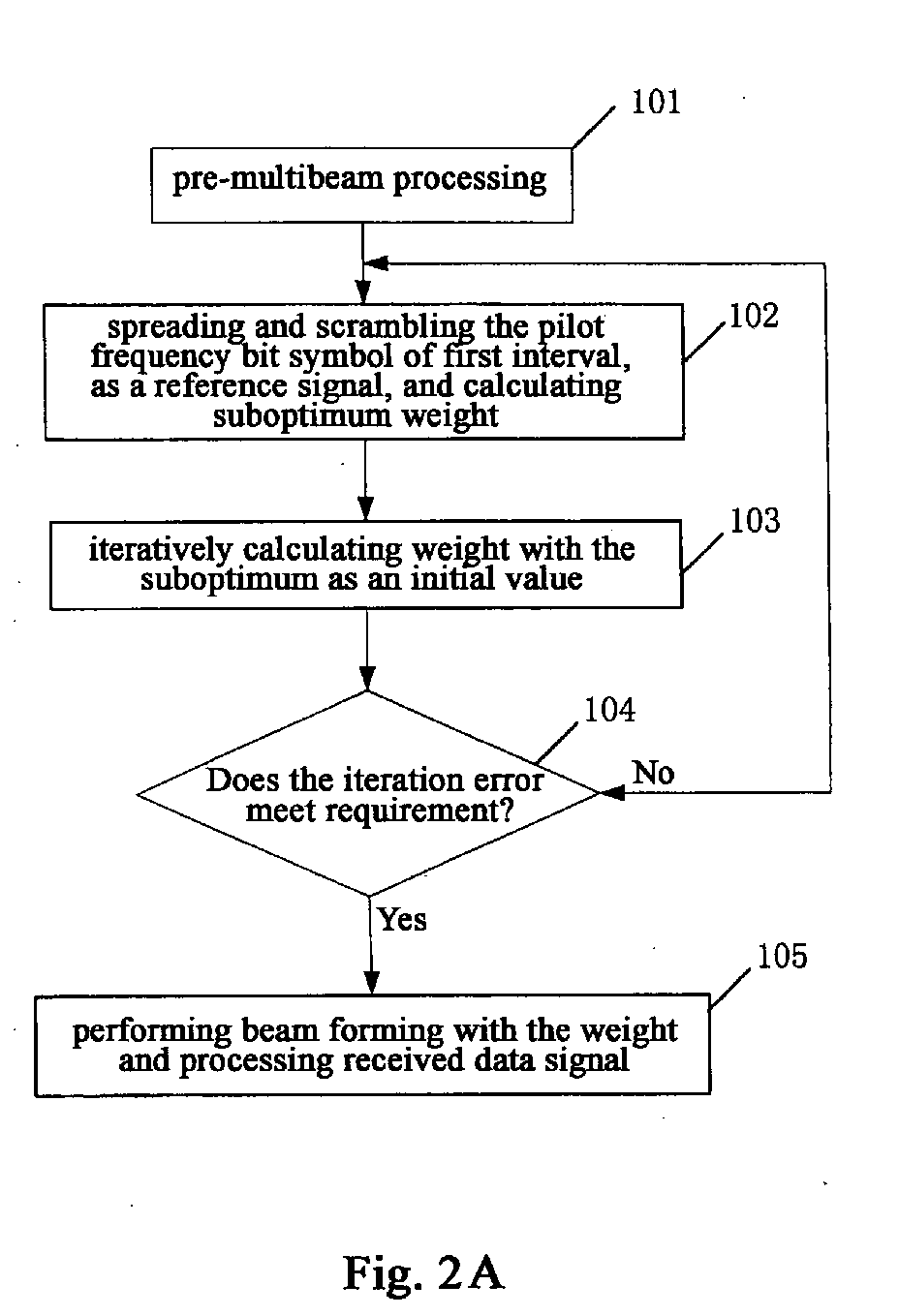
- Fig. 2A is a flow chart showing the beam forming method according to a preferred embodiment of the present invention.
- Step 101 in order to obtain the accurate time delays of respective multipathes before the adaptive beam forming, so as to ensure the beam forming of the smart antenna to be more reliable, the received arrays are implemented pre-multibeam processing in parallel simultaneously during the process of calculating the adaptive weight to supply an array received signal with aligned time delays to the adaptive weight calculation in real time.
- the processing includes generating a number of fixed narrow beams covering the sector, for example, in an embodiment, said sector is of 120° and four fixed narrow beams are generated herein (as shown in Fig. 1).
- the beam with maximal energy value can be found by implementing beam forming to the data received by the array and implementing time delay searching to the generated beam domain signal using said fixed narrow beams, and the time delay value in this beam is the time delay value of the array received signal.
- the data received by the arrays is implementing time delay aligning based on this time delay value and the array received vector of the information bits after the time delay aligning is represented by X .
- all the directions of arrival of mobile stations in the sector can be contained within the pre-multibeam by adjusting the size of the sector and the coverage area according to requirements.
- the number of the beams and the beam width can also be adjusted according to requirements. If the direction of arrival of a mobile station lies between two beams exactly, these two beams can be incorporated into one wide beam to ensure effective beam coverage.
- the pre-multibeam processing of the present invention can supply accurate time delay information to the adaptive calculation method of the smart antenna, and further ensure the accuracy and the reliability of the adaptive algorithm, and it is proved via experiments that the combination of the pre-multibeam processing and the adaptive algorithm in the present invention improves the signal-to-noise ratio of the received signals of the smart antenna greatly and achieves the superior performance of the smart antenna well, compared to the result of the simple adaptive algorithm without the pre-multibeam processing.
- Step 102 the suboptimum weight is calculated.
- a known pilot frequency symbol is regarded as a reference signal, and a correlation matrix is calculated based on the reference signal after performing spread spectrum and scramble and the array received vectors after aligning the time delays, and then the matrix serves as the suboptimum weight.
- a known pilot frequency bit is regarded as a reference signal, and the optimum weight is calculated based on the reference signal after performing spreading and scrambling and the array received vectors after the time delay aligning, and then the optimum weight serves as the initial value for post minimum mean square error iteration, since this initial value is closer to the ideal weight, the convergence rate will be improved greatly (It will be converged after 3-4 symbol bits sometimes), which meets the requirement for the real time processing of a communication system.
- Step 103 the suboptimum weight is regarded as an initial value and the weight is calculated iteratively. This Step will now be described in detail with reference to Fig. 2B.
- Step 111 the signal after the beam forming is de-spread and descrambled, wherein j represents the j th information symbol, K represents a spread factor, Imag() represents to calculate the imaginary part.
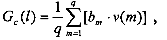
- Step 112 a complex gain of the l th piece of multipath incorporated by RAKE is estimated based on the result of the de-spreading and the descrambling with the pilot frequency section, wherein q is the number of pilot frequency bits, and b m is a known pilot frequency bit.
- the iterative calculation mentioned above is implemented at each interval of one frame.
- the signal data of the corresponding interval is processed smartly by taking the optimum weight for the first interval in the frame obtained through the above-mentioned method as the optimum weight for all the intervals in the frame, or taking the optimum weight for one random interval in the frame as the optimum weight for the latter intervals, which can further reduce the calculation amount of the weight iteration.
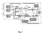
- Fig. 3 is a block diagram showing the construction of the smart antenna according to a preferred embodiment of the present invention.
- the smart antenna according to the embodiment comprises: an antenna array composed by a number of elements (1-M), a space domain forming module 21, a time domain processing module 22 and a re-spreading and iterating module 23.
- the space domain forming module 21, the time domain processing module 22 and the re-spreading and iterating module 23 also compose the beam forming apparatus for a smart antenna according to the embodiment of the present invention.
- the smart antenna and its beam forming apparatus according to the embodiment of the present invention will now be described in detail with reference to the drawings.
- the space domain forming module 21 comprises: pre-multibeam time delay searching units 215.1-215.M, each of which is connected to an antenna element respectively, a weight updating unit 213, multipliers 211.1-211.M and an adder 212.
- the weight updating unit 213 calculates weights iteratively by means of the minimum mean square error rule and based on the error information sent from the re-spreading and iterating module 23 or the signal spread and scrambled during the pilot frequency bits of the first interval which services as the reference signal for calculating the suboptimum weight, then the unit assigns the calculated weights to the corresponding multipliers (211.2-211.M).
- the time domain processing module 22 comprises: a descrambler 221, a de-spreader 222, a channel estimating and compensating RAKE unit (223, 224) and a determiner 225.
- the descrambler 221 and the de-spreader 222 are used to descramble and de-spread the signal which has been implemented the beam forming.
- the channel estimating and compensating RAKE unit 223 is used to process the descrambled data, to reduce the influence due to channels and to implement RAKE incorporating to the signals of multiple paths.
- the determiner 225 is used to determine the data bits to be output from the signal after the RAKE incorporating.
- the time delay information is searched by the pre-multibeam time delay searching unit 215 and then the array received signals are implemented time delay aligning so as to be baseband received signals [X 1 -X M ]. Next, the baseband signals will be processed.
- the signal will be divided into two signals, the one is input to the iteration error computing module 233 of the re-spreading and iterating module 23 as the minuend vector for the error computing, the other is input to the descrambler 221 of the time domain processing module 22.
- the Q channel data of the descrambled data then enters the de-spreader 222; as a result, the de-spread data has the unit of bit and can be processed by the channel estimating and compensating RAKE unit 223, 224 to reduce the influence due to the channels.
- the data processed by the determiner 225 are symbol bits of 1, -1 ..., and input to the re-spreading and iterating module 23.
- the symbol bits input from the time domain processing module 22 are input to the iteration error computing module 233 via the re-spreader 231 and the scrambler 232, and then minus the signal previously input from the adder 212 to obtain an error signal which will be input to the weight updating module 213 of the space domain beam forming module 21.
- the re-spread and scrambled signal of a known pilot frequency bit provided by the unit 235 serves as one input of the iteration error computing module 233 and minuses the signal previously input from the adder 212 to obtain an error signal which will be input to the weight updating module 213 of the space domain beam forming module 21.
- the reference signal input to the weight updating unit 213 and the aligned received signals [X 1 -X M ] are iterated based on the minimum mean square error rule to calculate the optimum weight.
- the data of the beam forming will be implemented descrambling, de-spreading, channel estimating and compensating and RAKE incorporating, and then it will be output.
- All the components composing the beam forming apparatus of the smart antenna according to the embodiment of the present invention can be hardware modules or software modules, and these modules can be integrated into a specific chip or FPGA, also part of them can be implemented by software in DSP.
- Fig.4 is a curve showing the simulation contraction between the output signal-to-noise ratios before and after the adaptive beam algorithm of the present invention performing the pre-multibeam.
- the abscissa in Fig. 4 represents the input signal-to-noise ratio, Eb/N0, with a variation range of 4-12dB.
- the ordinate represents the output signal-to-noise ratio. Both the interval units of the abscissa and the ordinate are 2dB.
- the simulation is under the conditions of a macrocell with 20 users, a data length of 20 frames and a symbol rate of 60 kbps, in this figure, "NO Beam” represents the adaptive beam forming method without pre-multibeam processing of the prior art, and "Beam+Algorithm” represents the adaptive beam forming method of the present invention, which uses the pre-multibeam and the de-spreading and re-spreading multi-objective array assisted by pilot frequencybits and based on the minimum mean square error rule.
- V represents the moving speed, with a unit of kmph.
- the output signal-to-noise ratio obtained through the present invention is close to 13dB, while the output signal-to-noise ratio obtained through the method without pre-multibeam processing is about 5.8dB, and the difference between them is about 7.2dB, likewise, when the input signal-to-noise ratio is 6, 8, 10 and 12dB, it has similar results, so the method of the present invention improves the output signal-to-noise ratio greatly, compared to the adaptive method without pre-multibeam processing of the prior art.
- Fig. 5 represent the bit error rates of the signals received through the methods and the structures of the prior art and the present invention respectively. Similarly, it can be seen from fig. 5 that the output bit error rate will be reduced greatly by using the method and the structure of the present invention, compared to the prior art.
Landscapes
- Engineering & Computer Science (AREA)
- Computer Networks & Wireless Communication (AREA)
- Signal Processing (AREA)
- Radio Transmission System (AREA)
- Variable-Direction Aerials And Aerial Arrays (AREA)
Abstract
Description

Claims (19)
- A beam forming method for a smart antenna, which comprises:implementing pre-multibeam processing and time delay aligning to array signals;calculating a suboptimum weight by means of a pilot frequencysymbol;iteratively calculating an optimum weight by means of said suboptimum weight as an initial value;forming a beam by means of said optimum weight.
- The beam forming method for a smart antenna according to claim 1, wherein, said step of implementing pre-multibeam processing to array signals comprises:generating a number of fixed beams covering a sector, and implementing beam forming to the data received by an array, by means of said fixed beams;implementing beam time delay searching to the generated beam domain signals, selecting the maximum beam of each multiple paths, and aligning the array data by means of the time delay value of this beam.
- The beam forming method for a smart antenna according to claim 2, wherein, the coverage area of the beam and the amount and the width of the beam can be adjusted with the size of the sector to ensure all the directions of arrival of the mobile stations in the sector are included within said pre-multibeam.
- The beam forming method for a smart antenna according to claim 1, wherein, said step of calculating the suboptimum weight comprises:spreading and scrambling the known pilot frequencybits of the first interval of a current frame, as a reference signal;based on the minimum mean square error rule, calculating the approximate solution of the correlation matrix of said reference signal and the array received signals after time delay aligning, as the suboptimum weight.
- The beam forming method for a smart antenna according to claim 1, wherein, said step of iteratively calculating the optimum weight comprises:forming beams for the array received signals after time delay aligning, by means of the initial weight;implementing descrambling and de-spreading to the received signals after beam forming, and determining control information;re-spreading and scrambling the determined control information, as an iteration reference signal;calculating iteration error by means of the iteration reference signal and the received signals after beam forming;calculating a new weight;iterating based on the new weight as the initial weight.
- The beam forming method for a smart antenna according to claim 5, wherein, when calculating the new weight, an iteration formula W r+1=W r +µ·X×E H is used, wherein, W i is the weight calculated by last iteration, µ is the step length of the iteration, E is the iteration error, E H is its conjugate transpose, r is the iteration reference signal, Y is the received signals after beam forming.
- The beam forming method for a smart antenna according to claim 5, wherein, in said step of determining, the information of a known pilot frequency bit serves as the determined output during the pilot frequency bit.
- The beam forming method for a smart antenna according to claim 5, wherein, before the step of forming beams by means of said optimum weight, said method further comprises:determining whether the iteration error meets requirement;if the iteration error does not meet requirement, repeating said step of calculating the suboptimum weight and said step of iteratively calculating the optimum weight.
- The beam forming method for a smart antenna according to claim 8, wherein, said step of determining comprises:calculating the mean square value of the iteration error;if the calculated mean square value of the iteration error is larger than a predetermined threshold, determining that the iteration error does not meet requirement, otherwise determining that the iteration error meets requirement.
- The beam forming method for a smart antenna according to claim 8, wherein, the optimum weight obtained in the first interval of each frame serves as the optimum weight of the whole frame to process the signals of all the intervals of the frame.
- A beam forming apparatus for a smart antenna, which comprises:a space domain forming module for implementing beam forming to the signals received by an antenna array, and said space domain forming module further comprises a pre-multibeam time delay searching unit for implementing pre-multibeam processing and time delay aligning to array signals;a time domain processing module for obtaining the transmitted data based on the signals beam-formed by said space domain forming module; anda re-spreading and iterating module for generating a reference signal based on the data information acquired by said time domain matched filtering module, calculating the iteration error and feeding it back to said space domain beam forming module.
- The beam forming apparatus according to claim11, wherein, said space domain forming module further comprises:a weight updating unit for calculating weights used for beam forming by means of the iteration error fed back from the re-spreading and iterating module;multipliers for multiplying the corresponding weights calculated the weight updating unit and the received signals of the elements of the corresponding antenna array; andan adder for adding the output of the multipliers.
- The beam forming apparatus according to claim11, wherein, said time domain processing module comprises:a descrambling and de-spreading unit for descrambling and de-spreading the signals beam-formed by the space domain forming module;a RAKE incorporating unit for incorporating the signals of multiple paths; anda determiner for determining the data to be transmitted from the signals after the RAKE incorporating.
- The beam forming apparatus according to claim 11, wherein said re-spreading and iterating module comprises:a re-spreading and scrambling unit for re-spreading and scrambling the transmitted data obtained by said time domain processing module, as an iteration reference signal;an iteration error computing unit for calculating the iteration error based on the iteration reference signal from said re-spreading and scrambling unit and the received signals beam-formed by said space domain forming module.
- The beam forming apparatus according to claim14, wherein, said weight updating unit of the space domain forming module iteratively calculates an optimum weight by means of the iteration error calculated by the iteration error computing unit.
- The beam forming apparatus according to claim 15, wherein, said weight updating unit of the space domain forming module calculates the cross correlation matrix of the spreading and scrambling signals of the known pilot frequency bit and the received pilot frequency range signals, based on the minimum mean square error rule to obtain a suboptimum weight, as the initial value of iteration calculating.
- The beam forming apparatus according to claim16, wherein, said weight updating unit re-calculates the suboptimum weight when it is determined that said iteration error does not meet requirement.
- The beam forming apparatus according to claim14, wherein, said iteration error computing unit regards the signal spread and scrambled by means of a known pilot frequency bit as the iteration reference signal during pilot frequency bits.
- A smart antenna, which comprises an antenna array composed by elements and the beam forming apparatus of claim 11-18.
Applications Claiming Priority (1)
| Application Number | Priority Date | Filing Date | Title |
|---|---|---|---|
| PCT/CN2002/000947 WO2004059793A1 (en) | 2002-12-31 | 2002-12-31 | Smart antenna, method and device for forming |
Publications (2)
| Publication Number | Publication Date |
|---|---|
| EP1580843A1 true EP1580843A1 (en) | 2005-09-28 |
| EP1580843A4 EP1580843A4 (en) | 2006-02-15 |
Family
ID=32661068
Family Applications (1)
| Application Number | Title | Priority Date | Filing Date |
|---|---|---|---|
| EP02792581A Ceased EP1580843A4 (en) | 2002-12-31 | 2002-12-31 | Smart antenna, method and device for forming |
Country Status (5)
| Country | Link |
|---|---|
| US (1) | US7362267B2 (en) |
| EP (1) | EP1580843A4 (en) |
| CN (1) | CN100429826C (en) |
| AU (1) | AU2002359956A1 (en) |
| WO (1) | WO2004059793A1 (en) |
Cited By (1)
| Publication number | Priority date | Publication date | Assignee | Title |
|---|---|---|---|---|
| CN101834648A (en) * | 2010-04-20 | 2010-09-15 | 新邮通信设备有限公司 | Method for generating weight value of intelligent antenna and base station |
Families Citing this family (9)
| Publication number | Priority date | Publication date | Assignee | Title |
|---|---|---|---|---|
| US7542870B2 (en) * | 2006-02-28 | 2009-06-02 | Ssi Technologies, Inc. | Immersed fuel level sensor |
| US8331265B2 (en) * | 2009-04-20 | 2012-12-11 | Samsung Electronics Co., Ltd. | System and method for adaptive beamforming training using fixed time window for heterogeneous antenna systems |
| CN108462521B (en) * | 2018-02-11 | 2021-03-05 | 西南电子技术研究所(中国电子科技集团公司第十研究所) | Anti-interference realization method of self-adaptive array antenna |
| CN110086553A (en) * | 2019-04-21 | 2019-08-02 | 上海无线通信研究中心 | Wave beam for millimeter-wave communication system is aligned test method and its system |
| CN110166098B (en) * | 2019-04-25 | 2022-02-01 | 河海大学 | Adaptive beam forming method for broadband phase-only transmission |
| CN110138428A (en) * | 2019-06-03 | 2019-08-16 | 浙江理工大学 | A kind of Beamforming Method under no receiving end feedback information |
| CN111555787B (en) * | 2020-04-24 | 2022-02-11 | 西安交通大学 | Iterative correction of artificial noise weights and low-bit feedback method for multi-transmit and single-receive systems |
| CN112711837B (en) * | 2020-12-23 | 2023-02-28 | 中国人民解放军空军工程大学 | A Beamforming Method Against Strong Interference under Low Snapshot |
| USD1078876S1 (en) * | 2025-03-20 | 2025-06-10 | Ying Liu | Dinosaur toy |
Family Cites Families (11)
| Publication number | Priority date | Publication date | Assignee | Title |
|---|---|---|---|---|
| KR100239177B1 (en) * | 1997-08-30 | 2000-01-15 | 윤종용 | Smart antenna receiving apparatus and method using pilot signal in cdma mobile communication system |
| CN1235391A (en) * | 1999-04-19 | 1999-11-17 | 董捷 | Self adaptable array antenna for pre-optimized shape beam for code division multi-access system |
| KR100351125B1 (en) * | 1999-07-26 | 2002-09-09 | 오성근 | smart antenna system using the structure of prebeamformer about each multipath and adaptive equalization combiner each frequency bins |
| JP4509297B2 (en) * | 2000-04-26 | 2010-07-21 | 三菱電機株式会社 | Spread spectrum receiver |
| US6369757B1 (en) * | 2000-07-05 | 2002-04-09 | Neo Reach, Inc. | Smart antenna with adaptive convergence parameter |
| FR2814014B1 (en) * | 2000-09-14 | 2002-10-11 | Mitsubishi Electric Inf Tech | MULTI-USER DETECTION METHOD |
| US7095814B2 (en) * | 2000-10-11 | 2006-08-22 | Electronics And Telecommunications Research Institute | Apparatus and method for very high performance space-time array reception processing using chip-level beamforming and fading rate adaptation |
| CN1160890C (en) * | 2000-11-15 | 2004-08-04 | 华为技术有限公司 | Digital beamforming method, module and array receiver thereof in wireless communication system |
| CN1139192C (en) * | 2000-12-14 | 2004-02-18 | 华为技术有限公司 | Method and receiver for uplink receiving adaptive array in wireless communication system |
| GB2386757A (en) * | 2002-03-16 | 2003-09-24 | Qinetiq Ltd | Signal processing |
| CN1486106A (en) * | 2002-09-24 | 2004-03-31 | 深圳市中兴通讯股份有限公司 | Apparatus and method for selfadaptive beam forming of intelligent antenna |
-
2002
- 2002-12-31 CN CNB028300912A patent/CN100429826C/en not_active Expired - Fee Related
- 2002-12-31 US US10/541,316 patent/US7362267B2/en not_active Expired - Lifetime
- 2002-12-31 WO PCT/CN2002/000947 patent/WO2004059793A1/en not_active Ceased
- 2002-12-31 EP EP02792581A patent/EP1580843A4/en not_active Ceased
- 2002-12-31 AU AU2002359956A patent/AU2002359956A1/en not_active Abandoned
Cited By (2)
| Publication number | Priority date | Publication date | Assignee | Title |
|---|---|---|---|---|
| CN101834648A (en) * | 2010-04-20 | 2010-09-15 | 新邮通信设备有限公司 | Method for generating weight value of intelligent antenna and base station |
| CN101834648B (en) * | 2010-04-20 | 2013-05-22 | 新邮通信设备有限公司 | Method for generating weight value of intelligent antenna and base station |
Also Published As
| Publication number | Publication date |
|---|---|
| WO2004059793A1 (en) | 2004-07-15 |
| CN1717843A (en) | 2006-01-04 |
| CN100429826C (en) | 2008-10-29 |
| AU2002359956A1 (en) | 2004-07-22 |
| US7362267B2 (en) | 2008-04-22 |
| EP1580843A4 (en) | 2006-02-15 |
| US20060114154A1 (en) | 2006-06-01 |
Similar Documents
| Publication | Publication Date | Title |
|---|---|---|
| US8670418B2 (en) | Successive interference cancellation | |
| US6430216B1 (en) | Rake receiver for spread spectrum signal demodulation | |
| DE60015546T2 (en) | MULTI-STAGE RAKE COMBINING PROCESS AND EQUIPMENT | |
| US6370397B1 (en) | Search window delay tracking in code division multiple access communication systems | |
| JP3406831B2 (en) | Array antenna system for wireless base station | |
| KR100757696B1 (en) | Code division multiple access system and method of operation with improved signal acquisition and processing | |
| JP4263365B2 (en) | Digital receiver and reception method for adjusting to the relative strength of traffic and pilot channel during soft handoff | |
| US20020054621A1 (en) | Apparatus and method for very high performance space-time array reception processing using chip-level beamforming and fading rate adaptation | |
| EP2165425B1 (en) | Signal processor for estimating signal parameters using an approximated inverse matrix | |
| US6782036B1 (en) | Smart antenna multiuser detector | |
| US6700923B1 (en) | Adaptive multiple access interference suppression | |
| JPH07202777A (en) | Method and equipment for receiving signal in multiplex route environment | |
| JP3813490B2 (en) | Spread spectrum rake receiver | |
| US7362267B2 (en) | Smart antenna, method and apparatus for adaptive beam forming | |
| US7889809B2 (en) | Weight vector calculation unit for beamforming using received and/or integrated signal without training signal | |
| EP1756984A1 (en) | Sir estimation in a wireless receiver | |
| EP1545023B1 (en) | A smart antenna and a method and a device for forming beam of the smart antenna | |
| JP3875998B2 (en) | Communication system apparatus and method | |
| US8259854B2 (en) | Channel estimation using common and dedicated pilots | |
| US20020181554A1 (en) | Adaptive rake receiving apparatus constrained with at least one constraint for use in mobile communication system and method therefor | |
| US7184465B2 (en) | Signal processing method and apparatus for a spread spectrum radio communication receiver | |
| US20030152174A1 (en) | Space-cover-time equalizer | |
| WO1998008319A1 (en) | Rake receiver for spread spectrum signal demodulation | |
| JP2001016148A (en) | Interference canceller using array antenna, interference replica generation unit | |
| JP2004080191A (en) | Weight estimation method, weight estimation apparatus, interference cancellation apparatus and receiver having the same |
Legal Events
| Date | Code | Title | Description |
|---|---|---|---|
| PUAI | Public reference made under article 153(3) epc to a published international application that has entered the european phase |
Free format text: ORIGINAL CODE: 0009012 |
|
| 17P | Request for examination filed |
Effective date: 20050715 |
|
| AK | Designated contracting states |
Kind code of ref document: A1 Designated state(s): AT BE BG CH CY CZ DE DK EE ES FI FR GB GR IE IT LI LU MC NL PT SE SI SK TR |
|
| AX | Request for extension of the european patent |
Extension state: AL LT LV MK RO |
|
| A4 | Supplementary search report drawn up and despatched |
Effective date: 20060102 |
|
| RIC1 | Information provided on ipc code assigned before grant |
Ipc: H04B 7/08 20060101ALI20051227BHEP Ipc: H01Q 25/00 20060101ALI20051227BHEP Ipc: H01Q 23/00 20060101ALI20051227BHEP Ipc: H01Q 21/00 20060101AFI20040720BHEP |
|
| DAX | Request for extension of the european patent (deleted) | ||
| STAA | Information on the status of an ep patent application or granted ep patent |
Free format text: STATUS: THE APPLICATION HAS BEEN REFUSED |
|
| 18R | Application refused |
Effective date: 20080726 |