CROSS-REFERENCE TO THE INVENTION
This application is based upon and claims the benefit of
priority from the prior Japanese Patent Application No. 2004-092864,
filed on March 26, 2004; the entire contents of which are incorporated
herein by reference.
BACKGROUND OF THE INVENTION
1. FIELD OF THE INVENTION
This invention relates to an information recording medium,
an information reproducing apparatus, an information reproducing
method and an information recording method.
2. DESCRIPTION OF THE RELATED ART
An optical disk is used as an information recording medium
for recording and reproducing information.
An art of increasing a total number of test write area (test
area) in proportion to an increase of optical disk capacity is
disclosed (See Patent document 1: Japanese Patent Laid-open
Application No. 2001-273637). Namely, a test write area is disposed
in an inner peripheral position, and its extension scaling factor
is discretely set. Then, an SYNC pattern of an ATIP wobble signal
is detected to determine the kind of the disc, and the total number
of test areas (test write area) is determined.
An art of an optical disk capable of setting a spare area
extendable to an outer peripheral side is disclosed (See Patent
document 2: Japanese Patent No. 3090316) . The position information
of the extendable spare area is described in position information
of a second spare area in a file entry area of the second spare area.
SUMMARY OF THE INVENTION
In the art disclosed in Patent document 1, the size of the
test write area (test area) cannot be set optionally, and there is
the possibility of causing substantial capacity reduction.
In the art disclosed in Patent document 2, the position
information of the extendable spare area cannot be rewritten in a
"recordable information storage medium", and the data structure
concerning the position information of the spare area cannot be taken.
In view of the above description, the present invention has
its object to provide an information recording medium, an information
reproducing apparatus, an information reproducing method and an
information recording method which make it easy to record and
reproduce information properly.
An information recording medium according to the present
invention includes a user information storage area which stores user
information, a test write area which is extendable and for test write
of information, a spare area which is extendable and capable of
alternatively storing user information, and a recording position
management information area including recordable range information
expressing recordable ranges in the aforesaid test write area and
the aforesaid spare area.
An information reproducing apparatus according to the present
invention includes an information reproducing device which
reproduces information from an information recording medium
including a user information storage area which stores user
information, a test write area which is extendable and for test write
of information, a spare area which is extendable and capable of
alternatively storing user information, and a recording position
management information area including recordable range information
expressing recordable ranges in the aforesaid test write area and
the aforesaid spare area.
An information reproducing method according to the present
invention includes reproducing information from an information
recording medium including a user information storage area which
stores user information, a test write area which is extendable and
for test write of information, a spare area which is extendable and
capable of alternatively storing user information, and a recording
position management information area including recordable range
information expressing recordable ranges in the aforesaid test write
area and the aforesaid spare area.
An information recording method according to the present
invention includes recording information in an information recording
medium including a user information storage area which stores user
information, a test write area which is extendable and for test write
of information, a spare area which is extendable and capable of
alternatively storing user information, and a recording position
management information area including recordable range information
expressing recordable ranges in the aforesaid test write area and
the aforesaid spare area.
BRIEF DESCRIPTION OF THE DRAWINGS
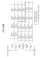
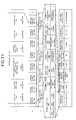
FIG. 1 is a diagram showing a point list (1) of an embodiment.
FIG. 2 is a diagram showing a point list (2) of the embodiment.
FIG. 3 is a diagram showing a point list (3) of the embodiment.
FIG. 4 is a diagram showing a point list (4) of the embodiment.
FIG. 5 is an explanatory diagram of a structure in the
embodiment of an information recording and reproducing apparatus.
FIG. 6 is an explanatory diagram of a detailed structure of
a peripheral part of a synchronous code position detecting unit in
this embodiment.
FIG. 7 is an explanatory diagram of an example of a signal
processing circuit using a slice level detection method.
FIG. 8 is a detailed explanatory diagram showing a slicer
circuit.
FIG. 9 is an explanatory diagram of an example of a signal
processing circuit using a PRML detection method.
FIG. 10 is an explanatory diagram of a structure in a viterbi
decoder.
FIG. 11 is a state transition diagram of a PR (1, 2, 2, 2,
1) class.
FIG. 12 is an explanatory diagram of a method of creating
a maker indicating a next border by overwrite processing.
FIG. 13 is a diagram showing an example of a structure and
dimension of an information storage medium.
FIG. 14 is an explanatory diagram of process steps in an
information reproducing apparatus or an information recording
apparatus.
FIG. 15 is a diagram showing a physical sector number setting
method of a recordable information storage medium or a single-layer
reproduction-only information storage medium.
FIGS. 16A and 16B are diagrams showing physical sector number
setting methods of reproduction-only information storage media
having double-layer structures.
FIG. 17 is a diagram showing a physical sector number setting
method in a rewritable information storage medium.
FIG. 18 is a diagram showing a general parameter setting example
in a reproduction-only information storage medium.
FIG. 19 is a diagram showing a general parameter setting example
in a recordable information storage medium.
FIG. 20 is a diagram showing a general parameter setting example
in a rewritable information storage medium.
FIG. 21 is a data structure comparison explanatory diagram
in a system lead-in area and a data lead-in area.
FIG. 22 is a data structure explanatory diagram in a recording
position management zone.
FIG. 23 is a data structure comparison explanatory diagram
in a data area and a data lead-out area.
FIG. 24 is a waveform (write strategy) explanatory diagram
of a record pulse.
FIG. 25 is a definition explanatory diagram of a record pulse
shape.
FIG. 26 is a structure explanatory diagram concerning a border
area in the recordable information storage medium.
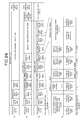
FIG. 27 is a data structure explanatory view in a control
data zone and an R physical information zone.
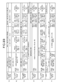
FIG. 28 is an information content comparison explanatory
diagrams in physical format information and R physical format
information.
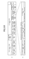
FIG. 29 is an information content comparison explanatory view
in disposition place information of a data area DTA.
FIG. 30 is a data structure explanatory diagram (1) in a
recording position management data.
FIG. 31 is a data structure explanatory diagram (2) (continued)
in the recording position management data.
FIG. 32 is a data structure explanatory diagram (3) (continued)
in the recording position management data.
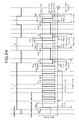
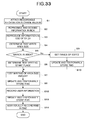
FIG. 33 is an explanatory view of process steps of setting
a test write area and test write.
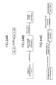
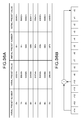
FIGS. 34A to 34C are conversion steps explanatory diagrams
until forming a physical sector structure.
FIG. 35 is a structure explanatory diagram in a data frame.
FIG. 36A is an explanatory diagram of initial values which
are given to a shift register when a frame after scramble is created.
FIG. 36B is an explanatory diagram of a circuit construction
of a feedback shift register for creating scramble bytes.
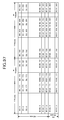
FIG. 37 is an explanatory diagram of an ECC block structure.
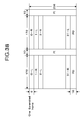
FIG. 38 is a frame arrangement explanatory diagram after
scramble.
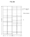
FIG. 39 is an explanatory diagram of an interleave method
of PO.
FIG. 40 is a structure explanatory diagramin a physical sector.
FIG. 41 is an explanatory diagram of a synchronous code pattern
content.
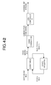
FIG. 42 is a diagram showing a construction of a modulation
block.
FIG. 43 is a diagram showing a connection rule for code words.
FIG. 44 is a diagram showing connection of a code word and
a sync code.
FIG. 45 is a diagram showing a separation rule for reproducing
code words.
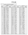
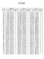
FIG. 46 is a diagram showing a conversion table in a modulation
method.
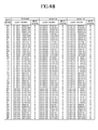
FIG. 47 is a diagram showing the conversion table in the
modulation method.
FIG. 48 is a diagram showing the conversion table in the
modulation method.
FIG. 49 is a diagram showing the conversion table in the
modulation method.
FIG. 50 is a diagram showing the conversion table in the
modulation method.
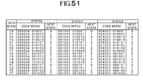
FIG. 51 is a diagram showing the conversion table in the
modulation method.
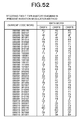
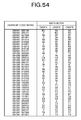
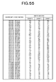
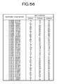
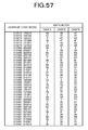
FIG. 52 is a diagram showing a demodulation table.
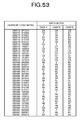
FIG. 53 is a diagram showing the demodulation table.
FIG. 54 is a diagram showing the demodulation table;
FIG. 55 is a diagram showing the demodulation table.
FIG. 56 is a diagram showing the demodulation table.
FIG. 57 is a diagram showing the demodulation table.
FIG. 58 is a diagram showing the demodulation table.
FIG. 59 is a diagram showing the demodulation table.
FIG. 60 is a diagram showing the demodulation table.
FIG. 61 is a diagram showing the demodulation table.
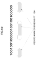
FIG. 62 is an explanatory diagram of a reference code pattern.
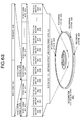
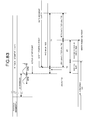
FIG. 63 is a data unit explanatory diagram of a recorded data
on an information storage medium of this embodiment.
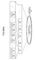
FIG. 64 is a comparison explanatory diagram of a data recording
type of each kind of information storage medium in this embodiment.
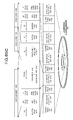
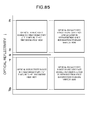
FIG. 65A is an explanatory diagram of comparison of a data
structure in the information storage medium of this embodiment with
a prior art example.
FIG. 65B is an explanatory diagram of comparison of the data
structure in the information storage medium of this embodiment with
the prior art example.
FIG. 65C is an explanatory diagram of comparison of the data
structure in the information storage medium of this embodiment with
the prior art example.
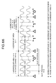
FIG. 66 is an explanatory diagram of 180 degrees phase
modulation in wobble modulation and an NRZ method.
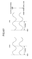
FIG. 67 is an explanatory view of relationship between the
wobble shapes and address bits in an address bit area.
FIG. 68 is a comparison table of a wobble position and a
recording place in the recordable information storage medium and
the rewritable information storage medium of this embodiment.
FIG. 69 is a comparison explanatory view of the wobble position
and the recording place in the recordable information storage medium
and the rewritable information storage medium of this embodiment.
FIGS. 70A and 70B are explanatory diagrams of address defining
methods in the recordable information storage medium and the
rewritable information storage medium of this embodiment.
FIG. 71 is a wobble address format explanatory diagram on
the recordable information storage medium of this embodiment.
FIG. 72 is an explanatory diagram of a gray code example.
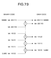
FIG. 73 is an explanatory diagram of a gray code conversion
algorithm.
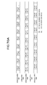
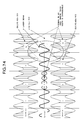
FIG. 74 is an explanatory diagram showing an example in which
an indefinite bit area is formed in a groove area.
FIG. 75 is an explanatory diagram of a disposition place of
a modulation area on the recordable information storage medium of
this embodiment.
FIG. 76 is a disposition explanatory view in a wobble data
unit concerning a primary disposition place and a secondary
disposition place of the modulation area.
FIG. 77 is a comparison explanatory diagram of disposition
relationship in a wobble sync pattern and a wobble data unit.
FIG. 78 is a disposition place explanatory view of a modulation
area in a physical segment on the recordable information recording
medium.
FIG. 79 is a comparison explanatory diagram of a data structure
in wobble address information in the rewritable information storage
medium and the recordable information storage medium according to
this embodiment.
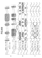
FIG. 80 is a relation explanatory diagram of a combination
method of a wobble sync pattern and type identifying information
of a physical segment and a disposition pattern of a modulation area.
FIG. 81 is a layout explanatory diagram in a recording cluster.
FIG. 82 is a data recording method explanatory view of a
rewritable data recorded on the rewritable information storage
medium.
FIG. 83 is a data random shift explanatory view of the
rewritable data recorded on the rewritable information storage
medium.
FIG. 84 is an explanatory view of a recording method of a
recordable data recorded on the recordable information storage
medium.
FIG. 85 is an explanatory view concerting a reflectivity of
an unrecorded part in an "H→L" recording film and an "L→H" recording
film.
DESCRIPTION OF THE EMBODIMENTS
An information storage medium such as an optical disk has
an Updated data area allocation area inside an RMD field 0, and in
that area, information which is the information of an Updated outer
limit of Data Recordable area and in a recordable range is written.
An extendable test write area (test area) and an extendable
alternate area (spare area) are settable in an outer peripheral part
of the information storage medium, and an area which is the result
of taking the above described extendable test write area (test area)
and the extendable alternate area (spare area) from an entire
recording area corresponds to the recordable range of the information
of the Updated outer limit of Data Recordable area and in the recordable
range.
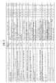
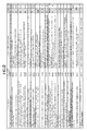
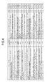
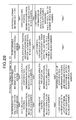
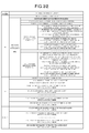
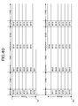
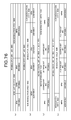
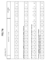
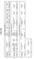
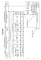
The points concerning an embodiment of the present invention
are summarized and described in FIGS. 1 to 4. The effects provided
when the respective points are combined are shown in the rows in
FIGS. 1 to 4, and the mark of □ (star) is given to the portion with
the highest contribution ratio to each effect, and marks of □ (double
circle), ○ (single circle) and □ (triangle) are given in the order
of higher contribution ratio. Outlines of the effects provided when
the respective points are combined are as follows.
Confirm the recording (rewrite or write) place by defect management
information 5. Recording of a stable and highly accurate record mark
Stable tracking and recording place confirmation are important.
Record at optimum speed based on recording speed information. 6. Handle both of "L→H recording film" and "H→L recording
film", achieve commonality of a circuit and realize simplification
of control.
Hereinafter, detailed embodiments will be described.
In the following explanation of the embodiments, the
explanation corresponding to each of the points shown in FIG. 1 to
FIG. 4 is partially included. The corresponding parenthesized point
code is given to the part of the explanation corresponding to each
of the points shown in FIG. 1 to FIG. 4.
An explanatory diagram of a structure in an embodiment of
the information recording and reproducing apparatus is shown in FIG.
5. In FIG. 5, an upper side from a control unit 143 mainly shows
an information record control system for an information storage medium.
An embodiment of the information reproducing apparatus corresponds
to a structure in FIG. 5 except for the aforementioned information
record control system. In FIG. 5, the thick solid arrows indicate
the flow of main information which means a reproduction signal or
a recording signal, the thin solid arrows indicate the flow of
information, the dashed line arrows indicate reference clock lines,
and the thin broken line arrows indicate a command instruction
direction.
An optical head not shown is disposed in an information
recording and reproducing unit 141 shown in FIG. 5. In this embodiment,
PRML (Partial Response Maximum Likelihood) is used for reproducing
information, and density of an information storage medium is enhanced
(FIG. 1 [A]).
As a result of various experiments, as a PR class for use,
adoption of PR (1, 2, 2, 2, 1) can enhance line density and enhance
reliability of the reproduction signal (demodulation reliability
at the time of occurrence of a servo correction error such as blooming
and a track deviation, for example). Therefore, in this embodiment,
PR (1, 2, 2, 2, 1) is adopted ((A1) in FIG. 1).
In this embodiment, a channel bit string after modulation
is recorded in the information storage medium in accordance with
(d, k; m, n) modulation regulation (meaning RLL (d, k) of m/n
modulation) . As a concrete modulation method, ETM (Eight to Twelve
Modulation) for converting 8-bit data into 12 channel bits (m=8,
n=12) is adopted, and as run-length limited RLL limitation for
limiting continuation of "0" in the channel bit string after
modulation, the condition of RLL (1, 10) in which the minimum value
of continuation of "0" is set as d=1 and the maximum value is set
as k=10 is imposed.
Aiming at densification of the information storage medium,
this embodiment shortens the channel bit interval near to the limit.
As a result, when the pattern of "101010101010101010101010" which
is the repetition of the pattern of d=1, for example, is recorded
in the information storage medium, and the data is reproduced in
the information recording and reproducing unit 141, the density is
close to the cutoff frequency of the MTF characteristic of the
reproducing optical system. Therefore, the signal amplitude of the
reproduction signal is in the state in which it is almost buried
in noise. Accordingly, as the method for reproducing a record mark
or pit with density enhanced near to the limit (cutoff frequency)
of the MTF characteristic, the art of PRML (Partial Response Maximum
Likelihood) is used.
Namely, a signal reproduced from the information recording
and reproducing unit 141 is subjected to reproduction waveform
correction by a PR equalizing circuit 130. The signal after passing
the PR equalizing circuit 130 is sampled and converted into a digital
amount in AD converter 169 in accordance with timing of a reference
clock 198 which is transmitted from a reference clock generating
circuit 160, and viterbi decoding processing is performed for it
in a viterbi decoder 156. The data after the viterbi decoding
processing can be processed in totally the same manner as the binarized
data at the conventional slice level.
When the art of PRML is adopted, an error rate of the data
after viterbi decoding increases if sampling timing is shifted in
the AD converter 169. Accordingly, in order to enhance accuracy
of the sampling timing, the information reproducing apparatus or
the information recording and reproducing apparatus of this
embodiment especially has a sampling timing extracting circuit
(combination of a Schmidt Trigger binary circuit 155 and a PLL circuit
174) separately.
The Schmidt Trigger circuit 155 has the characteristic in
that a specific range (actually the forward voltage value of diode)
is given to the slice reference level for binarization, and
binarization is achieved only when the specific range is exceeded.
Accordingly, for example, when the pattern of
"101010101010101010101010" is inputted as described above, the
signal amplitude is so small that switching of binarization does
not occur, but when, for example, "1001001001001001001001" or the
like, which is a sparser pattern than the above, is inputted, the
amplitude of the reproduction signal becomes large, and therefore,
polarity switching of the binary signal occurs in accordance with
the timing of "1" in the Schmidt trigger binarization circuit 155.
A NRZI (Non Return to Zero Invert) method is adopted in this
embodiment, and the position of "1" of the above-described pattern
and the record mark or the edge portion (border portion) of a pit
agree to each other.
In the PLL circuit 174, deviations of the frequency and phase
between the binarized signal which is the output of this Schmidt
Trigger binarization circuit 155 and the signal of the reference
clock 198 transmitted from the reference clock generating circuit
160 are detected, and the frequency and phase of the output clock
of the PLL circuit 174 are changed. In the reference clock generating
circuit 160, (frequency and phase of) the reference clock 198 is
fed back by using the output signal of the PLL circuit 174 and the
decoding characteristic information of the viterbi decoder 156
(information of the convergence length (distance to convergence)
in the pass metric memory in the viterbi decoder 156 which is not
shown concretely) so that the error rate after viterbi decoding
becomes low. The reference clock 198 generated in this reference
clock generating circuit 160 is utilized as the reference timing
at the time of processing the reproduction signal.
A synchronous code position extracting unit 145 detects the
existence position of a synchronous code (sync code) mixed in the
output data string of the viterbi decoder 156, and has the function
of extracting the start position of the above described output data.
With this start position as a reference, demodulation processing
is performed in a demodulation circuit 152 for the temporarily stored
data in a shift register circuit 170. In this embodiment, the data
is converted into the original bit string with reference to a
conversion table recorded in a demodulating conversion table
recording unit 154 for every 12 channel bits. Thereafter, error
correction processing is performed by an ECC decoding circuit 162,
and descrambling is performed by a descrambling circuit 159. In
the recording type (rewriting or recording) information storage
medium, address information is previously recorded by wobble
modulation. This address information is reproduced by wobble signal
detection unit 135 (namely, the content of the wobble signal is
distinguished), and necessary information for access to a desired
place is supplied to the control unit 143.
The information record control system existing at the upper
side fromthe control unit 143 will be explained. Data ID information
is generated from a Data ID generating unit 165 in accordance with
the recording position on the information storage medium, and when
copy control information is generated in a CPR_MAI data generating
unit 167, each kind of information of Data ID, IED, CPR_MAI and EDC
is added to the information to be recorded by a Data ID, IED, CPR_MAI
and EDC addition unit 168. Thereafter, the information is
descrambled in the descrambling circuit 157, after which, the ECC
block is constructed in an ECC encoding circuit 161. After it is
converted into a channel bit string in the modulation circuit 151,
the synchronous code is added in a synchronous code generating/adding
unit 146, and data is recorded in the information storage medium
in the information recording/reproducing unit 141. At the time of
modulation, a DSV (Digital Sum Value) value after modulation is
consecutively calculated in a DSV value calculating unit 148, and
is fed back to code conversion at the time of modulation.
A detailed structure of a peripheral part including the
synchronous code position detecting unit 145 shown in FIG. 5 is shown
in FIG. 6. The synchronous code is constituted of a synchronous
position detecting code part having a fixed pattern and a variable
code part. The position of the synchronous position detecting code
part having the above described fixed pattern is detected by a
synchronous position detecting code detecting unit 182 from a channel
bit string outputted from the viterbi decorder 156, and variable
code transfer units 183 and 184 extract the data of variable codes
existing before and after it, and determines which sync frame in
a sector described below the synchronous code detected by an
identifying unit 185, which is for a sync frame position identifying
code content, is located. The user information recorded on the
information storage medium is sequentially transferred to a shift
register circuit 170, a demodulation processing unit 188 in the
demodulation circuit 152, and the ECC decoding circuit 162 in this
order.
In the embodiment of the present invention, densification
(linear density is especially enhanced) of the information storage
medium is achieved by using PRML for reproduction in a data area,
a data lead-in area and a data lead-out area as shown in [A] in FIG.
1, and compatibility with a current DVD is secured and stability
of reproduction is secured by using a slice level detection method
for reproduction in a system lead-in area and a system lead-out area
as shown in [B] in FIG. 1.
An example of a signal reproducing circuit using the slice
level detection method which is used at the time of reproduction
in the system lead-in area and the system lead-out area is shown
in FIG. 7. A quadrant optical detector in FIG. 7 is fixed in an
optical head existing in the information recording and reproducing
unit 141 in FIG. 5. A signal which takes the sum total of a detection
signal capable of being obtained from each optical detection cell
of the quadrant optical detector is called a lead channel 1 signal
here. A preamp to a slicer in FIG. 7 means the detailed structure
in the slice level detection circuit 132 in FIG. 5. A reproduction
signal obtained from the information storage medium passes through
a high pass filter which cuts off lower frequency components than
the reproduction signal frequency band, and thereafter, is subjected
to waveform equalizing processing by a pre-equalizer. According
to the experiment, it is found out that as for this pre-equalizer,
by using a 7-tap equalizer, the reproduction signal can be detected
with the smallest circuit scale and high accuracy, and therefore,
the 7-tap equalizer is also used in this embodiment. A VFO circuit
and PLL part in FIG. 7 correspond to a PLL circuit in FIG. 5, and
a demodulation circuit and an ECC decoding circuit in FIG. 7 correspond
to the demodulation circuit 152 and the ECC decoding circuit 162
in FIG. 5.
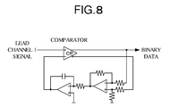
A detailed structure in the slicer circuit in FIG. 7 is shown
in FIG. 8. A binarization signal after slicing is generated by using
a comparator. In this embodiment, a low pass filter output signal
is set at a slice level at the time of binarization for the inversion
signal of binary data after binarization by using the duty feedback
method. The cutoff frequency of the low pass filter is set at 5kHz
in this embodiment. If this cutoff frequency is high, the slice
level varies early and therefore, the influence of noise is easily
given, and if the cutoff frequency is low on the other hand, response
of the slice level is late, and therefore, the influence of dust
and flaw on the information storage medium is easily given. The
cutoff frequency is set at 5kHz in consideration of the relationship
between the aforementioned RLL (1, 10) and the reference frequency
of the channel bit.
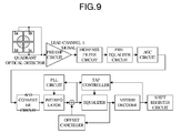
A signal processing circuit using the PRML detection method
which is used for signal reproduction in the data area, the data
lead-in area and the data lead-out area is shown in FIG. 9. A quadrant
optical detector in FIG. 9 is fixed in the optical head existing
in the information recording and reproducing unit 141 in FIG. 5.
The signal taking the total sum of the detection signal obtained
from each of optical detection cells of the quadrant optical detector
is called a lead channel 1 signal here.
A detailed structure in the PR equalizing circuit 130 in FIG.
5 is constituted by each circuit from a preamp circuit to a tap
controller, equalizer, and an offset canceller in FIG. 9. A PLL
circuit in FIG. 9 is a part of the inside of the PR equalizing circuit
130 in FIG. 5, and means a different thing from the Schmidt Trigger
binarization circuit 155 in FIG. 5.
The primary cutoff frequency of a bypass filter circuit in
FIG. 9 is set at 1 kHz. The pre-equalizer circuit uses a 7-tap
equalizer as in FIG. 7 (use of 7-tap makes it possible to detect
the reproduction signal with the smallest circuit scale and high
accuracy) .
Sample clock frequency of an A/D converter circuit is 72 MHz,
and digital is set at 8-bit output. If the influence of the level
variation (DC offset) of the entire reproduction signal is exerted
in the PRML detecting method, an error easily occurs at the time
of viterbi demodulation. The structure is designed to correct offset
by the offset canceller by using a signal obtained from the output
of the equalizer in order to remove the influence. In the example
shown in FIG. 9, adaptive equalization processing is performed in
the PR equalizing circuit 130. Therefore, a tap controller for
automatically correcting each tap coefficient in the equalizer by
utilizing the output signal of the viterbi decoder 156 is used.
The structure in the viterbi decoder 156 shown in FIG. 5 or
FIG. 9 is shown in FIG. 10. The branch metrics for all the branches
which can be estimated for the input signal are calculated in the
branch metric calculating part, and the value is sent to the ACS.
The ACS is the abbreviated name of Add Compare Select, which calculates
the pass metric which can be obtained by adding the branch metric
corresponding to each pass which can be estimated in the ACS, and
transfers the calculated result to a pass metric memory. At this
time, calculation processing is performed with reference to the
information in the pass metric memory in the ACS. Each pass
(transition) situation which can be estimated and the value of pass
metric calculated in the ACS corresponding to each pass are
temporarily stored in the pass memory. The pass metric corresponding
to each pass is compared in the output switching part, and the pass
of which pass metric value is minimum is selected.
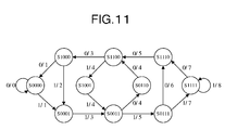
The state transition in the PR (1, 2, 2, 2, 1) class in the
embodiment of the present invention is shown in FIG. 11. As for
the transition of the state which can be taken in the PR (1, 2, 2,
2, 1) class, only the transition shown in FIG. 11 is possible, and
the pass which is capable of existing (being estimated) at the time
of decoding is determined based on the transition diagram of FIG.
11 in the viterbi decoder 156.
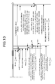
FIG. 13 shows a structure and a dimension of the information
storage medium in the embodiment of the present invention. As
examples, the following three kinds of information storage medium
can be cited.
- "Reproduction-only information storage medium" only for
reproduction and incapable of recording
- "Recordable information storage medium" capable of
recording only once
- "Rewritable information storage medium" capable of
rewriting any number of times.
As shown in FIG. 13, most of the structures and dimensions
are made common in the above described three kinds of information
storage media. In any of three kinds of information storage media,
a burst cutting area BCA, a system lead-in area SYLDI, a connection
area CNA, a data lead-in area DTLDI, and a data area DTA are disposed
from an inner peripheral side.
Data lead-out areas DTLDO are disposed in outer peripheral
parts in all media except for the OPT type reproduction-only medium.
A middle area MDA is disposed at the peripheral part in the OPT type
Information is recorded in a shape of emboss (prepit) in the
system lead-in area SYLDI, and in any of recordable and rewritable
types, this area is for reproduction-only (non-recordable). In the
reproduction-only information storage medium, information is also
recorded in the shape of emboss (prepit) in the data lead-in area
DTLDI. On the other hand, in the recordable and rewritable
information storage media, the data lead-in area DTLDI becomes an
area in which new information by record mark formation is recordable
(rewritable in the rewritable type).
As will be described later, in the recordable and rewritable
information storage media, in the data lead-out area DTLDO, the area
in which the new information is recordable (rewritable in the
rewritable type), and a reproduction-only area in which information
is recorded in the shape of emboss (prepit) exist mixedly.
As described above, in the data area DTA, the data lead-in
area DTLDI, the data lead-out area DTLDO and the middle area MDA
shown in FIG. 13, densification (line density is especially enhanced)
of the information storage medium is achieved by using PRML for
reproduction of the signal recorded therein ([A] in FIG. 1), and
in the system lead-in area SYLDI and the system lead-out area SYLDO,
compatibility with the current DVD is secured and stabilization of
reproduction is secured by using the slice level detecting method
for reproduction of the signal recorded therein ([B] in FIG. 1).
Unlike the current DVD standard, in the embodiment shown in
FIG. 13, the burst cutting area BCA and the system lead-in area SYLDI
do not overlap each other, but are positionally separated ((B2) in
FIG. 1). By physically separating both of them, interference between
the information recorded in the system lead-in area SYLDI at the
time of information reproduction and the information recorded in
the burst cutting area BCA is prevented, and therefore, information
reproduction with high precision can be ensured.
As another embodiment with respect to the embodiment shown
in (B2) in the above described FIG. 1, there is a method of previously
forming microscopic recessed and projecting shapes in the disposition
place of the burst cutting area BCA when the "L→H" type recording
film is used, as shown in (B3) in FIG. 1. In the embodiment of the
present invention, the explanation that not only the conventional
H→L type recording film but also the L→H type recording film is
incorporated in the standard and the selection range of the recording
film is enlarged to make it possible to record athigh speed and supply
a medium at low price ((G2) in FIG. 1) will be made in the part where
the explanation concerning the polarity (discrimination of whether
H→L or L→H) information of the record mark existing at the 192nd
byte in FIG. 28 is performed later. As will be described later,
in the embodiment of the present invention, the case where the "L→H"
type recording film is used is also considered.
The data (bar code data) to be recorded in the burst cutting
area BCA is recorded by locally exposing the recording film to laser.
As shown in FIG. 21, the system lead-in area SYLDI is formed in an
embossed pit area 211, and therefore, a reproduction signal from
the system lead-in area SYLDI tends to decrease in light reflection
amount as compared with a light reflection level from a mirror surface
210. If the burst cutting area BCA is brought into the mirror surface
state similarly to the mirror surface 210, and the L→H type recording
film is used, the reproduction signal from the data recorded in the
burst cutting area BCA tends to increase more in light reflection
amount than the light reflection level from the mirror surface 210
(of the unrecorded state). As a result, a large difference occurs
between the positions of the maximum level and minimum level
(amplitude level) of the reproduction signal from the data formed
in the burst cutting area BCA, and the positions of the maximum level
and the minimum level (amplitude level) of the reproducing signal
from the system lead-in area SYLDI.
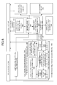
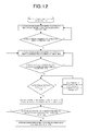
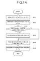
As will be described later in the explanation of FIG. 21 (and
((B4) in FIG. 1), the information reproducing apparatus or the
information recording and reproducing apparatus perform processing
in the sequence of the following (1) to (5). This processing content
will be shown in FIG. 14.
"(1) Reproduce information in the burst cutting area BCA"
- "(2) Reproduce information in an information data zone
CDZ in the system lead-in area SYLDI"
- "(3) Reproduce information in the data lead-in area DTLDI
(in the case of recordable or rewritable type)"
- "(4) Readjust (optimize) a reproduction circuit constant
in a reference code recording zone RCZ"
- "(5) Reproduce information recorded in the data area DTA
or record new information"
Therefore, if there is a large difference between the amplitude
level of the reproduction signal from the data formed in the burst
cutting area BCA and the amplitude level of the reproduction signal
from the system lead-in area SYLDI, there arises the problem of
reducing reliability of information reproduction. In order to solve
the problem, this embodiment has the characteristic that the
microscopic recessed and projecting shapes are previously formed
in this burst cutting area BCA when the "L→H" type recording film
is used for the recording film ((B3) in FIG. 1).
By previously forming the microscopic recessed and projecting
shapes, the light reflection level becomes lower than the light
reflection level from the mirror surface 210 due to optical
interference effect at the stage before the data (bar code data)
is recorded by local laser exposure, and the difference between the
amplitude level of the reproduction signal (detection level) from
the data formed in the burst cutting area BCA and the amplitude level
of the reproduction signal (detection level) from the system lead-in
area SYLDI reduces to a large extent. As a result, reliability of
information reproduction is enhanced, and the effect that the
processing when shifting from the above described (1) to (2) becomes
easy.
In the case of using the "L→H" type recording film, there
is the method of adopting the embossed pit area 211 as in the system
lead-in area SYLDI as a concrete content of the microscopic recessed
and projecting shapes previously formed in the burst cutting area
BCA. As the other examples, there is the method of adopting a groove
area 214, or a land area and groove area 213 as in the data lead-in
area DTLDI and the DATA area DTA.
As explained in the embodiment ((B2) in FIG. 1) in which the
system lead-in area SYLDI and the burst cutting area BCA are separately
disposed, if the inside of the burst cutting area BCA and the embossed
pit area 211 overlap each other, the noise component of the
reproduction signal from the data formed in the burst cutting area
BCA increases due to unnecessary interference.
As an example of the microscopic recessed and projecting shapes
in the burst cutting area BCA, it is considered to form the microscopic
recessed and projecting shapes in the groove area 214 or the land
area and groove area 213 instead of forming it in the emboss bit
area 211. As a result, the noise component of the reproduction signal
from the data formed in the burst cutting area BCA due to unnecessary
interference decreases, and quality of the reproduction signal is
enhanced.
If the track pitch of the groove area 214 or the land area
and groove area 213 formed in the burst cutting area BCA is conformed
to the track pitch of the system lead-in area SYLDI, manufacturability
of the information storage medium is enhanced. Namely, at the time
of producing a master of the information storage medium, the embossed
pit in the system lead-in area is produced with the feeding motor
speed of the aligner part of the master recording apparatus made
constant. At this time, the track pitch of the groove area 214 or
the land area and groove area 213 formed in the burst cutting area
BCA is conformed to the track pitch of the embossed pit in the system
lead-in area SYLDI, and thereby, the motor speed can be kept constant
continuously in the burst cutting area BCA and the system lead-in
area SYLDI. Therefore, it is not necessary to change the speed of
the feeding motor in mid course, and therefore, variation in pitch
hardly occurs, thus enhancing manufacturability of the information
storage medium.
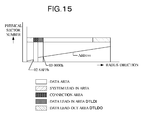
In all of the above-described three kinds of information
storage media, the minimum management unit of the information to
be recorded in the information storing media is a sector unit of
2048 bytes. A physical address of the above described sector unit
of 2048 bytes is defined as a physical sector number. A setting
method of the physical sector number in the recordable information
storage medium and the reproduction-only information storage medium
having single-layer structure is shown in FIG. 15. The physical
sector number is not given to the inside of the burst cutting area
BCA and the connection area CNA, but the physical sector numbers
are set for the system lead-in area SYLDI, the data area DTA and
the data lead-out area DTLDO in ascending order from the inner
circumference. The physical sector numbers are set so that the final
physical sector number of the system lead-in area SYLDI becomes
"026AFFh", and the physical sector number at the start position of
the data area DTA becomes "030000h".
There are two kinds of physical sector number setting methods
of the reproduction-only information storage media each having a
double-layer structure as shown in FIGS. 16A to 16B. One is parallel
placement (Parallel Track Path) PTP shown in FIG. 16A, and has the
structure in which the physical number setting method shown in FIG.
15 is applied to both the two layers. The other method is opposite
placement (Opposite Track Path) OPT shown in FIG. 16B, in which the
physical sector number is set from the inner circumference to the
outer circumference in ascending order in the layer at the front
(Layer 0) and the physical sector number is set from the outer
circumference to the inner circumference in ascending order in the
layer at the back side (layer 1) on the other hand. In the case
of the placement of OPT, a middle area MDA, a data lead-out area
DTLDO and a system lead-out area SYLDO are disposed.
A physical sector number setting method in the rewritable
information storage medium is shown in FIG. 17.
In FIG. 17, Zone, Nominal radius (mm), Number of Physical
segment per track, Number of tracks, Start Physical sector number
(hex value) and End Physical sector number (hex value) in each of
Land and Groove are shown with respect to each of System Lead-in
area, Connection area, Data Lead-in area, Data area and Data Lead-out
area.
In the rewritable information storage medium, the physical
sector numbers are respectively set for the land area and groove
area. The rewritable information storage medium has the structure
in which the data area DTA is divided into 19 zones.
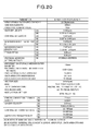
FIG. 18 shows each parameter value of this embodiment in the
reproduction-only information storage medium, FIG. 19 shows each
parameter value of this embodiment in the recordable information
storage medium, and FIG. 20 shows each parameter value of this
embodiment in the rewrite-only information storage medium.
As is understood from comparison of FIG. 18 or FIG. 19 and
FIG. 20 (especially the comparison of the part (B)), the rewrite-only
information storage medium is enhanced in recording capacity by
closing up the track pitch and line density (data bit length) with
respect to the reproduction-only or the write-only information
storage medium. As will be described later, in the rewrite-only
information storagemedium, the influence of crosstalk of the adjacent
tracks is reduced to close up the track pitch by adopting the land
groove record.
All of the reproduction-only information storage medium, the
recordable information storage medium and rewritable information
storage medium have the characteristic that the data bit length and
track pitch (corresponding to the record density) of the system
lead-in/out areas SYLDI/SYLDO are made larger than the data
lead-in/out areas DTLDI/DTLDO ((B1) in FIG. 1). Compatibility with
the current DVD is secured by making the data bit length and track
pitch of the system lead-in/out areas SYLDI/SYLDO close to the value
of the lead-in area of the current DVD.
In the embodiment of the present invention, as in the current
DVD-R, a level difference of embossing of the system lead-in/out
areas SYLDI/SYLDO of the recordable information storage medium is
set to be small. This brings about the effect that the depth of
the pre-groove of the recordable information storage medium is made
small, and the reproduction signal modulation degree from the record
mark formed on the pre-groove by recording is made high. On the
other hand, as the reaction, there arises the problem that the
modulation degree of the reproduction signal from the system
lead-in/out areas SYLDI/SYLDO becomes low. For this, the data bit
length (and track pitch) of the system lead-in/out areas SYLDI/SYLDO
is made large, and thereby, the repetitive frequency of pits and
spaces at the closest position is kept apart from the optical cutoff
frequency of the MTF (Modulation Transfer Function) of the objective
lens for reproduction (is made significantly small). As a result,
the amplitude of the reproduction signal from the system lead-in/out
areas SYLDI/SYLDO is incresed, and stabilization of reproduction
can be realized.
Comparison of the detailed data in the system lead-in SYLDI
and the data lead-in DTLDI in various kinds of information storage
media is shown in FIG. 21. (a) in FIG. 21 shows the data structure
of the reproduction-only information storing medium, (b) in FIG.
21 shows the data structure of the rewritable information storage
medium, and (c) in FIG. 21 shows the data structure of the recordable
information storage medium.
As shown in (a) of FIG. 21, except that only the connection
zone CNZ is the mirror surface 210, the insides of all the system
lead-in area SYLDI, data lead-in area DTLDI and the data area DTA
are the embossed pit area 211 where embossed pits are formed, in
the reproduction-only information storage medium.
The part where the inside of the system lead-in area SYLDI
is the embossed pit area 211, and the connection zone CNZ has the
mirror surface 210 is common. As shown in (b) of FIG. 21, in the
rewritable information storage medium, the land area and groove area
213 are formed in the data lead-in area DTLDI and the data area DTA,
and in the recordable information storage medium, the groove area
214 is formed in the data lead-in area DTLDI and the data area DTA.
Information is recorded by forming the record mark in the land area
and the groove area 213 or the groove area 214.
An initial zone INZ indicates the start position of the system
lead-in SYLDI. As semantic information recorded in the initial zone
INZ, data ID (Identification Data) information including the above
described physical sector number or logical sector number is
discretely disposed. Information of the data frame structure
constituted of data ID, IED (ID Error Detection code), main data
recordinguserinformation, andEDC (ErrorDetectionCode) isrecorded
in one physical sector as will be described later, and information
of the above-described data frame structure is also recorded in the
initial zone INZ. However, all the information of the main data
recording user information is all set at "00h" in the initial zone
INZ, and therefore, the semantic information in the initial zone
INZ is only the above described data ID information. The position
of the present head can be known from the information of the physical
sector number or the logical sector number recorded in this data
ID information. Namely, on starting information reproduction from
the information storage medium in the information recording and
reproducing unit 141 in FIG. 5, when reproduction is started from
the information in the initial zone INZ, the information of the
physical sector number or the logical sector number recorded in the
data ID information is extracted first. While the present position
in the information storage medium is being confirmed, shift to a
control data zone CDZ is made.
Buffer zones 1 and 2, BFZ1 and BFZ2 are each constituted of
32 ECC blocks. As shown in FIG. 18 to FIG. 20, one ECC block is
constituted of 32 physical sectors, and therefore, 32 ECC blocks
correspond to 1024 physical sectors. In the buffer zones 1 and 2,
BFZ1 and BFZ2, the information of the main data is all set at "00h"
as in the initial zone INZ.
The connection zone CNZ which exists in the connection area
(Connection Area) CNA is the area for physically separating the system
lead-in area SYLDI and the data lead-in area DTLDI, and this area
becomes the mirror surface where any embossed pit or pre-groove does
not exist.
A reference code recording zone (Reference code zone) RCZ
of the reproduction-only information storage medium and the
recordable information storage medium is the area used for adjusting
the reproduction circuit of the reproduction apparatus (for example,
for automatic adjustment of each tap coefficient value at the time
of adaptive equalization performed in the tap controller in FIG.
9) , and the information of the aforementioned data frame structure
is recorded therein. The length of the reference code is the same
as one ECC block (=32 sectors).
It is the characteristic of this embodiment that reference
code recording zones (Reference code zones) RCZ of the
reproduction-only information storage medium and the recordable
information storage medium are disposed adjacently to the data areas
(Data Areas) DTA ((A2) in FIG. 1). In any of the structures of the
current DVD-ROM disc and current DVD-R disc, a control data zone
is disposed between the reference code recording zone (Reference
code zone) and the data area (Data Area), and the reference code
recording zone and the data area are spaced from each other. If
the reference code recording zone and the data area are spaced from
each other, an inclination amount and optical reflectivity of the
information storage medium, or (in the case of the recordable
information storage medium), the recording sensitivity of the
recording film changes a little, and there arises the problem that
even if the circuit constant of the reproducing apparatus is adjusted
at the reference code recording zone, the optimal circuit constant
in the data area is shifted.
In order to solve the above described problem, the reference
code recording zone (Reference code zone) RCZ is disposed adjacently
to the data area (Data Area) DTA. As a result, when the circuit
constant of the information reproducing apparatus is optimized in
the reference code recording zone (Reference code zone), the optimized
state is also kept at the same circuit constant in the adjacent data
area (Data Area) DTA.
When a signal is desired to be reproduced with high accuracy
at the optional place in the data area (Data Area) DTA, it is preferable
to pass the following steps (1) to (4). As a result, signal
reproduction at the target position becomes possible with extremely
high accuracy.
Guard track zones 1 and 2, GTZ1 and GTZ2 existing in the
recordable information storage medium and the rewritable information
storage medium are the area for defining the start border position
of the data lead-in area DTLDI and the border position of a disc
test zone DKTZ and a drive test zone DRTZ. This area is defined
as the area where recording by the record mark formation must not
be performed. The guard track zones 1 and 2, GTZI and GTZ2 exist
in the data lead-in area DTLDI. Therefore, in this area, the
pre-groove area is previously formed in the recordable information
storage medium and the groove area and the land area are previously
formed in the rewritable information storage medium. The wobble
addresses are previously recorded in the pre-groove area or the groove
are and the land area as shown in Figure 18 to Figure 20, and therefore,
the current position in the information storage medium can be
determined by using the wobble addresses.
The disk test zone DKTZ is the area which is set for performing
quality test (evaluation) by the manufacturer of the information
recording medium.
The drive test zone DRTZ is secured as the area for test writing
before the information recording and reproducing apparatus records
information into the information storage medium. The information
recording and reproducing apparatus previously performs test writing
in this area, and after determining the optimal recording condition
(write strategy), it can record information in the data area DTA
under the optimal recording condition.
A disc identification zone DIZ existing inside the rewritable
information recording medium ((b) in FIG. 21) is the optional
information recording area, and a recordable area for each set with
the manufacturer name information of the recording and reproducing
apparatus and the related added information and Drive description
constituted of the area where the manufacturer can record uniquely
as one set.
Defect management areas 1 and 2, DMA 1 and 2 existing inside
the rewritable information storage medium ((b) in FIG. 21) are the
place where defect management information inside the data area DTA
is recorded, and spare spot information or the like when a defect
spot occurs, for example, is recorded.
A data structure in a recording position management zone RMZ
existing in the recordable information storage medium ((c) in FIG.
21) is shown in FIG. 22. (a) in FIG. 22 shows the same thing in
(c) in FIG. 21, and enlarged diagram of the recording position
management zone RMZ in (c) in FIG. 21 is shown in (b) in FIG. 22.
In the recording position management zone RMZ, the data
regarding the recording position management is collectively recorded
in one recording position management data(Recording Management Data),
and each time the content of the recording management data RMD is
updated, new recording management data RMD is recorded at the rear
side in sequence as a new recording management data RMD. Namely,
the recording position management data (Recording Management Data)
RMD is recorded in the size unit of one physical segment block (the
physical segment block will be explained later), and is recorded
at the rear in sequence as a new recording management data RMD each
time the data content is updated.
The example of (b) in FIG. 22 shows the example in which the
recording management data RMD #1 is recorded first, but the management
data is changed, and the data after the change (after updated) is
recorded immediately after the recording management data RMD #1 as
recording management data RMD #2.
Accordingly, an unrecorded area 206 exists in the recording
management data RMZ so that further recording is possible. The
concrete information content in the recording management data RMD
will be described later by using FIG. 30 to FIG. 32. The information
content of an R physical information zone RIZ shown in (c) of FIG.
21 will be also explained in detail later in the explanation of FIG.
27 to FIG. 29.
The characteristics of this embodiment lies in that as shown
in FIG. 21, in each of the reproduction-only, recordable, and
rewritable information storing media, the system lead-in area is
disposed at the opposite side of the data area with the data lead-in
area therebetween ((B4) of FIG. 1) and as shown in FIG. 13, the burst
cutting area BCA and the data lead-in area DTLDI are disposed at
the opposite sides with the system lead-in area SYLDI therebetween.
When the information storage medium is inserted into the
information reproducing apparatus or the information recording and
reproducing apparatus shown in FIG. 5, the information reproducing
apparatus or the information recording and reproducing apparatus
perform processing in the order of the following (1) to (5) . This
processing content is shown in the above described FIG. 14.
As shown in FIG. 21, information is disposed in order from
the inner circumferential side along the sequence of the above
described processing, and therefore, unnecessary access processing
to the inner circumference is not required. Accordingly, it is
possible to reach the data area DTAwith the number of accesses reduced,
and therefore, there is provided the effect of advancing the start
time of reproduction of the information recorded in the data area
DTA or recording of new information. The slice level detectionmethod
is utilized for signal reproduction in the system lead-in area SYLDI
(FIG. 1 [B]), and PRML is used for signal reproduction in the data
lead-in area DTLDI and the data area DTA (FIG. 1 [A]). Therefore,
when the data lead-in area DTLDI and the data area DTA are made to
adjoin each other, and reproduction is performed in order from the
inner circumferential side, stable signal reproduction is
continuously possible by only switching from the slice level detection
circuit to the PRML detection circuit only once between the system
lead-in area SYLDI and the data lead-in area DTLDI. Therefore, since
the number of switching times of reproduction circuit following the
reproducing steps is small, the processing control is simplified
and time required for starting reproduction in the data area becomes
short.
Comparison of the data structures in the data area DTA and
the data lead-out area DTLDO in various kinds of information storing
media is shown in FIG. 23. In FIG. 23, (a) shows the data structure
of the reproduction-only information storage medium, (b) and (c)
show the data structures of the rewritable information storage medium,
and (d) to (f) show the data structures of the recordable information
storage medium. (b) and (d) especially show the data structure at
the initial time (before recording), and (c), (e) and (f) show the
data structures in the state in which recording (record or rewrite)
advances to some extent.
As shown in (a) in FIG. 23, the data recorded in the data
lead-out area DTLDO and the system lead-out area SYLDO have the data
frame structures (the data frame structure will be described later)
as the buffer zones 1, 2 BFZ1 and 2 in FIG. 21, and all the values
of the main data in them are set at "00h" . In the reproduction-only
information storage medium, all the area in the data area DTA can
be used as the prerecorded area 201 of the user data. As will be
described later, in all embodiments of the recordable information
storage medium and the rewritable information storage medium, the
rewritable/recordable ranges 202 to 205 of the user data are smaller
than the data area DTA.
In the recordable information storage medium or the rewritable
information storage medium, a spare area (Spare Area) SPA is provided
in the innermost circumferential part of the data area DTA. When
a defective place occurs in the data area DTA, replacement processing
is performed by using the above described spare area SPA, and in
the case of the rewritable information storagemedium, its replacement
history information (defect management information) is recorded in
the defective management areas 1 and 2 (DMA1, 2) in (b) of FIG. 21,
and defect management areas 3 and 4 (DMA3, 4) in (b) and (c) of FIG.
23. Defect management information recorded in the defect management
areas 3 and 4 (DMA3, 4) in (b) and (c) of FIG. 23 have the same content
as the information recorded in the defect management areas 1 and
2 (DMA1, 2) in (b) of FIG. 21.
In the case of the recordable information storage medium,
the replacementhistory information (defect management information)
in the case where replacement processing is performed is recorded
in copy information C_RMZ which is the record content in the recording
position management zone existing in the data lead-in area DTLDI
shown in (c) in FIG. 21 and in a border zone which will be described
later. Defect management is not performed in the current DVD-R disc.
Therefore, as the number of manufactured DVD-R discs increases, the
DVD-R discs having defective spots in part come to appear, and the
demand for enhancement in reliability of information recorded in
the recordable information storage media is growing.
In the example shown in FIG. 23, the spare area SPA is also
set for the recordable information storage medium to make defect
management by replacement processing possible (FIG. 1 [C]). As a
result, it becomes possible to enhance reliability of recorded
information by also performing defect management processing for the
recordable information storage medium having a defective spot in
part. In the rewritable information storage medium or the recordable
information storage medium, the information recording and
reproducing apparatus determines on the user side when many defects
occur, whereby the spare place can be enlarged by automatically
setting the extended spares area (Extended Spare Area) ESPA, ESPA1
and ESPA2 for the state immediately after selling to the user shown
in (b) and (d) in FIG. 23.
The extended spare areas ESPA, ESPA1 and ESPA2 are made settable
in this manner, and thereby, the media having a number of defects
for the reason of manufacture can be on sale. As a result,
manufacturing yield is enhanced, thus making it possible to reduce
the cost of the media.
When the extended spare areas ESPA, ESPA1 and ESPA2 are
additionally provided in the data area DTA as shown in (c), (e) and
(f) in FIG. 23, the rewritable or recordable ranges 203 and 205 of
the user data decrease, and it is necessary to manage the position
information. In the rewritable information storage medium, its
information is recorded in the defect management areas 1 to 4 (DMA1
to 4) and a control data zone CDZ as will be described. In the case
of recordable information storage medium, its information is recorded
in the data lead-in area DTLDI and a recording management zone RMZ
existing in a border out BRDO as will be described later. As will
be described later, its information is recorded in recording position
management data (Recording Management Data) RMD in the recording
position management zone RMZ. The recording management data RMD
is updated and recorded in the recording management zone RMZ each
time the management data content is updated, and therefore, even
if the extended spare area is reset many times(the example in (e)
of FIG. 23 shows the state in which the extended spare area 1 EAPA1
is set, even after all the extended spare area is used up, there
is so many defects that it is necessary to set another spare area,
and therefore, extended spare area 2 ESPA2 is further set at a later
date), it is possible to update and manage the data timely ((C1)
in FIG. 23).
Guard track zones 3 (GTZ3) shown in (b) and (c) in FIG. 23
are disposed for separation between a defect management area 4 (DMA4)
and a drive test zone DRTZ, and a guard track zone GTZ4 is disposed
for separation between a disc test zone DKTZ and a servo calibration
zone (Servo Calibration Zone) SCZ. The guard track zones 3 and 4
(GTZ 3, 4) are defined as the area in which recording by formation
of the record marks must not be performed as in the guard track zones
1 and 2 (GTZ1 and 2) shown in FIG. 21. Since the guard track zones
3 and 4 (GTZ3, GTZ4) exist inside the data lead-out area DTLDO, in
this area, a pre-groove area is previously formed in the recordable
information storage medium, and a groove area and a land area are
previously formed in the rewritable information storage medium. The
wobble addresses are previously recorded in the pre-groove area,
the groove area and the land area, as shown in FIG. 18 to FIG. 20,
and therefore, the current position in the information storage medium
is determined by using the wobble addresses.
The drive test zone DRTZ is secured as the area for test writing
before the information recording and reproducing apparatus records
information into the information storage medium as in FIG. 21. The
information recording and reproducing apparatus previously performs
test writing in this area, and after determining the optimum recording
condition (write strategy), information can be recorded in the data
area DTA with the optimum write strategy.
The disc test zone DKTZ is the area for the manufacturer of
the information storage medium to perform a quality test (evaluation)
as in FIG. 21.
In all the areas in the data lead-out areas DTLDO except for
servo calibration zones (Servo Calibration Zone) SCZ, the pre-groove
area is previously formed in the recordable information storage medium,
the groove area and the land area are previously formed in the
rewritable information storage medium, and it is made possible to
record the record mark (record or rewrite).
As shown in (c) and (e) in FIG. 23, the inside of the servo
calibration zone (Servo Calibration Zone) SCZ is the embossed pit
area 211 as in the system lead-in area SYLDI instead of the pre-groove
area 214, or the land area and groove area 213 (FIG. 1 [D]). In
this zone, a continuous track by the embossedpit is formed, continuing
from the other areas of the data lead-out area DTLDO. This track
consecutively continues in a spiral form, extends over 360 degrees
along the circumference of the information storage medium to form
the embossed pit.
This zone is provided to detect the inclination amount of
the information storage medium by using a DPD (Differential Phase
Detect) method. When the information storage medium inclines,
offset occurs to the amplitude of the track deviation detection signal
using the DPD method. At this time, it becomes possible to detect
the inclination amount by the offset amount and detect the inclination
direction by the offset direction with high accuracy. By utilizing
this principle, the embossed pit by which the DPD detection can be
performed is previously formed at the outermost peripheral portion
(the peripheral portion in the data lead-out area DTLDO) of the
information storage medium, whereby inclination detection at low
cost with high accuracy is made possible without adding a special
component (for inclination detection) to the optical head
existing inside the information recording and reproducing unit 141
in FIG. 5. By further detecting the inclination amount of this outer
circumferential portion, stabilization of the servo (by inclination
amount correction) can be also realized in the data area DTA.
In this embodiment, the track pitch in this servo calibration
zone SCZ is conformed to those in the other zones in the data lead-out
area DTLDO (FIG. 1 (D1)). As a result, manufacturability of the
information storage medium is enhanced, and reduction in cost of
the medium by enhancement of yield is made possible. Namely, in
the recordable information storage medium, pre-groove is formed in
the other zones in the data lead-out area DTLDO. At the time of
manufacturing the master of the recordable information storage medium,
the pre-groove is made by making the speed of the feeding motor of
the aligner part of the master recording apparatus constant. At
this time, by conforming the track pitch in the servo calibration
zone SCZ to those in the other zones in the data lead-out area DTLDO,
the feeding motor speed can be also continuously kept constant in
the servo calibration zone SCZ. Therefore, a pitch variation hardly
occurs, and manufacturability of the information storage medium is
enhanced.
As another example, there is the method of conforming at least
either the track pitch or the data bit length in the servo calibration
area SCZ to the track pitch or the data bit length of the system
lead-in area SYLDI (FIG. 1 (D2)).
Measuring the inclination amount and the inclination
direction in the servo calibration area SCZ by using the DPD method
and realizing servo stabilization in the data area DTA by utilizing
the result in the data area DTA are described above. As the method
for estimating the inclination amount in the data area DTA at this
time, it is considered to previously measure the inclination amount
and its direction in the system lead-in area SYLDI by the same DPD
method and estimate the inclination amount by utilizing the
relationship with the measurement result in the servo calibration
zone SCZ.
In the case of using the DPD method, the offset amount of
the detection signal amplitude with respect to the inclination of
the information storage medium and the direction in which the offset
comes out change dependently on the track pitch and the data bit
length of the embossed pitch. Accordingly, it is considered to
conform at least either the track pitch or the data bit length in
the servo calibration zone SCZ to the track pitch or the data bit
length of the system lead-in area SYLDI. In this manner, the detection
characteristics concerning the offset amounts of the detection signal
amplitude and the directions in which the offset comes out can be
conformed to each other in the servo calibration area SCZ and the
system lead-in area SYLDI. As a result, there arises the effect
of making it easy to obtain correlation between both of them and
facilitate estimation of the inclination amount and the direction
in the data area DTA.
As shown in (c) in FIG. 21 and (d) in FIG. 23, in the recordable
information storage medium, drive test zones DRTZ are provided at
two spots in the inner circumferential side and the outer
circumferential side. As the number of test writings performed in
the drive test zone DRTZ is larger, the optimal recording condition
can be sought in detail by varying the parameter minutely, and
recording accuracy to the data area DTA is enhanced. In the rewritable
information storage medium, reuse of the drive test zone DRTZ by
overwriting is made possible. However, in the recordable
information storage medium, when the recording accuracy is enhanced
by increasing the number of test writings, there arises the problem
of using up the drive test zone DRTZ in a short time. In order to
solve the problem, this embodiment has the characteristic that it
is made possible to set extended drive test zone (Extended Drive
Test Zone) EDRTZ along the direction of the inner circumference from
the outer circumferential portion, and it is made possible to extend
the drive test zone ((E2) in FIG. 1).
As the characteristics concerning the setting method of the
extended drive test zone and the test writingmethod in the set extended
drive test zone, the following 1 to 3 can be cited in this embodiment.
In the case of performing reset as in (f) in FIG. 23, the
set place of the extended spare area 1 (ESPA1) shown in (e) in FIG.
23 is regarded as "the extended spare area already used up", and
management is performed considering that the unrecorded area (area
where additional test writing is possible) exists only in the extended
spare area 2 (ESPA2) in the extended drive test zone EDRTZ. In this
case, nondefective information which is recorded in the extended
spare area 1 (ESPA1) and used for replacement is transferred to an
unused area in the extended spare area 2 (ESPA2) as it is, and the
defect management information is rewritten. At this time, start
position information of the data lead-out area DTLDO which is reset
is recorded in the position information of the newest (updated) data
area DTA of the RMD field 0 in the recording management data RMD
as shown in FIG. 30.
The waveform of the record pulse (write strategy) for
performing test writing in the above described drive test zone is
shown in FIG. 24 and the definition of the record pulse shape is
shown in FIG. 25.
The structure of the border area in the recordable information
storage medium will be explained with FIG. 26. When one border area
is set in the recordable information storage medium for the first
time, a bordered area (Bordered Area) BRDA#1 is set at the inner
circumferential side (the nearest side to the data lead-in area DTLDI),
and thereafter, border-out (Border-out) BRDO is formed behind it,
as shown in (a) in FIG. 26.
When the next bordered area (Bordered Area) BRDA #2 is desired
to be set, the next border-in (Border-in) BRDI (of #1) is formed
behind the previous border-out BRDO (of #1) as shown in (b) in FIG.
26, and thereafter, the next bordered area BRDA #2 is set. When
the next bordered area BRDA #2 is desired to be closed, the border-out
BRDO (of #2) is formed just behind it. In this embodiment, the state
in which the next border-in (Border-in) BRDI (of #1) is formed behind
the previous border-out BRDO (of #1) and is paired with the border-out
BRDO (of #1) is called a border zone (Border Zone) BRDZ. The example
of setting the extended drive test zone EDRTZ in the data area DTA
is shown in (b) in FIG. 26.
The state after finalizing (Finalization) the recordable
information storage medium is shown in (c) in FIG. 26. The example
in which the extended drive test zone EDRTZ is incorporated in the
data lead-out area DTLDO and the extended spare area ESPA is further
set is shown in (c) in FIG. 26. In this case, the recordable range
205 of the user data is filled with the final border-out BRDO so
that the recordable range 205 of the user data is not left unfilled.
The detailed data structure in the border zone BRDZ explained
above is shown in (d) in FIG. 26. Each information is recorded in
a size unit of one physical segment block (Physical Segment Block)
which will be described later.
Copy information C_RMZ of the content recorded in the recording
position management zone is recorded in the initial part in the
border-out BRDO, and a border stopping marker (Stop Block) STB
indicating that this is the border-out BRDO is recorded.
When the next border-in BRDI further comes, the initial marker
indicating that a border area comes next (Next Border Marker) NBM
is recorded in the "N1st" physical segment block counted from the
physical segment block in which this border stopping marker (Stop
Block) STB is recorded. Then, the second marker NBM indicating that
a border area comes next is recorded in the "N2nd" physical segment
block, and the third marker NBM indicating that a border area comes
next is recorded in the "N3rd" physical segment block. In this manner,
the markers NBM are discretely recorded at the three spots in total
for each size of one physical segment block.
Updated physical format information (Updated Physical Format
Information) U_PFI is recorded in the next border-in BRDI.
When the next border area does not come (in the final border-out
BRDO) in the current DVD-R or DVD-RW disc, the place where "the marker
NBM indicating the next border" is to be recorded (the place of one
physical segment block size) shown in (d) in FIG. 26 is kept to be
"the place where no data is recorded". When the border close is
performed in this state, this recordable information storage medium
(current DVD-R or DVD-RW disc) is in the state capable of reproduction
in the conventional DVD-ROM drive or the conventional DVD player.
In the conventional DVD-ROM drive or the conventional DVD player,
track deviation detection using the DPD (Differential Phase Detect)
method is performed by utilizing the record mark recorded on this
recordable information storage medium (current DVD-Ror DVD-RW disc) .
However, in the above described "place where no data is recorded",
a record mark does not exist over one physical segment block size,
and therefore, track deviation detection using the DPD (Differential
Phase Detect) method cannot be performed. Therefore, there exists
the problem that the track servo does not perform stably.
As the solution to the problems of the above described current
DVD-R or DVD-RW disc, the following [1] to [5] can be cited in this
embodiment.
As will be explained in detail later by using FIGS. 65A to
65C, data fields 411 to 418 for recording the user data and guard
areas 441 to 448 are alternately recorded on the information storage
medium. A set of combination of each of the data fields 411 to 418
and each of the guard areas 441 to 448 is called a data segment 490,
and one data segment length corresponds to one physical segment block
length.
In the PLL circuit shown in FIG. 5, lead-in of PLL is easily
performed especially in VFO areas 471 and 472 shown in FIGS. 65A
to 65C. Accordingly, even if PLL is off, another lead-in of PLL
can be easily performed by using the VFO areas 471 and 472 if it
is in the place immediately before the VFO areas 471 and 472, and
the influence as the whole system in the information recording and
reproducing apparatus or the information reproducing apparatus is
reduced.
By utilizing this situation, [3] the overwriting situation
is changed in accordance with the place in the data segment as described
above ((L1) in FIG. 4), and overwriting amount of a specific pattern
is increased at the rear part near the VFO areas 471 and 472 in the
same data segment. In this manner, it is made easy to determine
"the marker indicating the next border", and the accuracy
deterioration of the signal PLL at the time of reproduction can be
prevented.
As is explained in detail by using FIGS. 65A to 65C and FIG.
45, one physical sector is constructed by combination of the place
where a sync code 433 (SY0 to SY3) is disposed and sync data 434
disposed between the synch codes 433. The information recording
and reproducing apparatus or the information reproducing apparatus
extracts the sync code 433 (SY0 to SY3) from a channel bit string
recorded on the information storage medium, and detects a break of
the channel bit string. The position information (physical sector
number or logical sector number) of the data recorded on the
information storage medium is extracted from the information of the
data ID in FIG. 35 as will be described later. The error of the
data ID is detected by using IED disposed immediately behind it.
Accordingly, in this embodiment, [5] overwriting is
prohibited on the data ID and IED, and [4] overwriting is partially
performed in the sync data 432 except for the sync code 431 ((L2)
in FIG. 4), thereby also making it possible to detect the data ID
position by using the sync code 431 and reproduce information recorded
in the data ID (read the content) in "the marker NBM indicating the
next border".
In order to explain the above described content more
specifically, the flow chart at the time of performing overwriting
in the place of "the marker NBM indicating the next border" is shown
in FIG. 12. When the control unit 143 of the information recording
and reproducing apparatus shown in FIG. 5 receives the setting
instruction of a new border via the interface unit 142 (ST1), the
control unit 143 controls the information recording and reproducing
unit 141 and starts reproduction of the exiting bordered area BRDA
disposed at the end (ST2) . Subsequently, the information recording
and reproducing unit 141 keeps tracing along the pre-groove in the
bordered area BRDAwhile tracking until it detects the border stopping
marker STB in the border-out BRDO (ST3).
As shown in (d) in FIG. 26, behind the border stopping marker
STB, the markers NBM each indicating the next border which is recorded
in the specific pattern are already disposed in the N1st, N2nd and
N3rd physical segment block. The information recording and
reproducing unit 141 counts the number of physical segment blocks
while continuing reproduction in the border-out BRDO (ST4), and seeks
the position of the above described marker NBM indicating the next
border (ST5).
As described above, as a specific example of the method of
"[3] the overwriting situation is changed in accordance with the
place in the same data segment ((L1) in FIG. 4)", a wide overwriting
area is taken in at least the final physical sector in the same data
segment. When the final physical sector in the data segment is
detected (ST6), overwriting is performed from immediately behind
the data ID and IED to the end of the final physical sector with
the data ID and IED left (without overwriting in the data ID and
IED) (ST9).
In the same data segment other than at least the final physical
sector, overwriting is partially performed in a specific pattern
in the sync data 432 (ST7) while avoiding the area of the sync code
431 (SY0 to SY3) shown in FIG. 40 or FIG. 63 which will be described
later ((L2) in FIG. 4). The above described process is performed
for each marker NBM indicating each border, and after overwriting
processing for the marker NBM indicating the third border is finished
(ST9), a new border-in BRDI is recorded, after which user data is
recorded in the bordered area BRDA (ST10).
The logical record unit of the information recorded in the
bordered area BRDA shown in (c) in FIG. 26 is called R zone (R Zone) .
Accordingly, one bordered area BRDA is constructed by at least one
or more R zones. In the current DVD-ROM, the file system called
"UDF bridge" in which both the file management information in
conformity with the UDF (Universal Disc Format) and the file
management information in conformity with ISO9660 are simultaneously
recorded in one information storage medium is adopted for its file
system. Here, in the fail management method in conformity with
ISO9660, there is the rule that one file has to be recorded continuously
without fail in the information storage medium (namely, it is
prohibited to divide and dispose the information in one file at
discrete positions on the information storage medium). Accordingly,
when the information is recorded in conformity with the above
described UDF bridge, for example, all information constituting one
file is continuously recorded, and therefore, the area where this
one file is continuously recorded can be adapted to constitute one
R zone.
FIG. 27 shows the data structure in the control data zone
CDZ and the R-physical information zone RIZ. As shown in (b) in
FIG. 27, physical format information (Physical Format Information)
PFI and medium manufacturing information (Disc Manufacturing
Information) DMI exist in the control data zone CDZ. The R-physical
information zone RIZ is constituted of the medium manufacturing
information (Disc Manufacturing Information) DMI and R-physical
format information (R-Physical Format Information) R_PFI.
Information 251 concerning the medium manufacturing country
and medium manufacturer belonging country information 252 are
recorded in the medium manufacturing information DMI (FIG. 2 [F]).
When the information storage medium on sale makes infringement of
the patent, infringement warning is issued to the country where the
manufacturing place exists or the country where the information
storage medium is consumed (used) in many cases. The manufacturing
place (country name) is found out by making it mandatory to record
the above described information in the information storage medium,
and patent infringement warning is easily issued, whereby the
intellectual property is protected and the advancement of technology
is promoted. Further, the other medium manufacturing information
253 is also recorded in the disc manufacturing information DMI.
This embodiment is characterized in that the kind of
information to be recorded is specified in accordance with the
recording place (relative byte position fromthe head) in the physical
format information PFI or the R physical format information R_PFI
(FIG. 2 [G]). Namely, common information 261 in the DVD family is
recorded in the area of 32 bytes which is from 0 byte to the 31st
byte as the recording place in the physical format information PFI
or the R physical format information R_PFI. 96 bytes from the 32nd
byte to the 127th byte are for recording common information 262 in
the HD_DVD family which is the target of this embodiment. 384 bytes
from the 128th byte to the 511th byte is for recording respective
individual information (peculiar information) 263 concerning each
written standard type and a part version. 1536 bytes from the 512th
byte to the 2047th byte is for recording information corresponding
to each revision. By achieving commonality of the information
position in the physical format information in accordance with the
information content like this, the place of the recorded information
is made common irrespective of the kinds of the media. Therefore,
commonality and simplification of reproduction processing of the
information reproducing apparatus or the information recording and
reproducing apparatus are achieved. The common information 261 in
the DVD family which is recorded in the place from 0 byte to the
31st byte is divided into information 267 which is recorded in the
place from 0 byte to the 16th byte and recorded in common in the
reproduction-only information storage medium, the rewritable
information storage medium and the recordable information storage
medium, and information 268 which is recorded in the place from the
17th byte to the 31st byte and recorded in common in the rewritable
information storage medium and the recordable information storage
medium, but not recorded in the reproduction-only type.
Concrete information contents in the physical format
information PFI or the R-physical format information R_PFI shown
in FIG. 27 and the comparison of information in the physical format
information PFI in accordance with the kind of medium (whether the
reproduction-onlytype,rewritable type or recordable type)areshown
in FIG. 28. As the information 267 recorded in common to all the
reproduction-only type, rewritable type and recordable type in the
common information 261 in the DVD family, there are sequentially
in the byte position 0 to 16, information of the type of the written
standard (reproduction-only/rewritable/recordable) and version
number information, medium size (diameter) and maximum possible data
transfer rate information, medium structure (single layer or
double-layer, presence or absence of embossed pit/recordable
area/rewritable area), recording density (linear density and track
density) information, position information of the data area DTA,
and presence and absence information of the burst cutting area BCA
(all present in this embodiment).
As the information 268 which is the common information 261
in the DVD family and is recorded in common in the rewritable type
and the recordable type, there are cited sequentially from the 28th
byte to the 31st byte, revision number information specifying the
maximum recording speed, revision number information specifying the
minimum recording speed, revision number table (application revision
number), class state information, and extended (part) version
information. Giving the information from the 28th byte to the 31st
byte corresponds to the characteristic of this embodiment of giving
the revision information corresponding to the recording speed to
the recording area of the physical format information PFI or the
R-physical format information R_PFI ((G1) in FIG. 2).
When the medium which is enhanced in recording speed into
the medium to double-speed, quadruple-speed or the like is
conventionally developed, extremely troublesome labor to newly
recompose the written standard has to be done corresponding to it
eachtime. On the other hand, in this embodiment, the written standard
is divided into a written standard which changes in version when
the content is changed to a large extent (version book) and a revision
book which is issued by changing revision corresponding to a small
change such as recording speed, and only the revision book which
is updated in revision is issued each time the recording speed is
enhanced. Thereby, extension function to future medium
corresponding to the high-speed recording is ensured, and it is made
possible to be adapted to the standard by the simple method of revision,
thus providing the effect of being adaptable to high speed when a
new high-speed recording-compliant medium is developed.
The characteristic of this embodiment lies in that the revision
numbers are made separately settable at the maximum value and the
minimum value of the recording speed especially by separately
providing the column of the revision number information specifying
the maximum recording speed at the 17th byte, and the column of the
revision number information specifying the minimum recording speed
at the 18th byte ((G1α) in FIG. 2). For example, when a recording
film recordable at extremely high speed is developed, such a recording
film is capable of recording at the extremely high speed, but when
the recording speed is lowered, such a recording film cannot perform
recording suddenly, or the recording film capable of lowering the
recordable minimum speed is very expensive in many cases. On the
other hand, the revision numbers are made separately settable at
the maximum value and the minimum value of the recording speed as
in this embodiment, whereby the selection range of the developable
recording film is widened, and as the result, there arises the effect
of making it possible to supply media capable of higher-speed
recording and media at lower price.
The information recording and reproducing apparatus of the
embodiment of the present invention previously has the information
of the possible maximum recording speed and possible minimum recording
speed in each revision. When an information storage medium is put
on this information recording and reproducing apparatus, the
information in the physical format information PFI or the R-physical
format information R_PFI is read first in the information recording
and reproducing unit 141 shown in FIG. 5. Subsequently, with
reference to the information of the possible maximum recording speed
and possible minimum recording speed of each revision previously
recorded in the memory unit 175 in the control unit 143 based on
the obtained revision number information, the possible maximum
recording speed and the possible minimum recording speed of the
information recording medium which ismountedthereon are determined.
Further, recording is performed at the optimal recording speed based
on the result.
Next, the meaning of the peculiar information 263 of the type
and version of each written standard from the 128th byte to the 511th
byte, and the meaning of the information content 264 peculiarly
settable in each revision from the 512th byte to the 2047th byte,
which are shown in (c) in FIG. 27 will be explained. Namely, in
the peculiar information 263 of the type and version of each written
standard from the 128th bite to the 511th byte, meaning of the record
information content in each byte position is consistent irrespective
of the rewritable information storage medium and the recordable
information storage medium which differ in type. The information
content 264 peculiarly settable for each revision from the 512th
byte to the 2047th byte is allowed to differ in the meaning of the
record information content at each byte position not only when the
difference between the rewritable information storage medium and
the recordable information storagemediumwhichdiffer intypes exists,
but also when the revision differs in the same kind of media.
As shown in FIG. 28, as the information in the peculiar
information 263 of the type and version of each written standard
in which the meaning of the record information content is consistent
at each byte position in the rewritable information storage medium
and the recordable information storage medium which differ in types,
medium manufacturer name information, added information from the
medium manufacturer, record mark polarity (discrimination of whether
H→L or L→H) information, linear speed information at the time of
recording or at the time of reproduction, the rim intensity value
of an optical system along the circumferential direction, the rim
intensity value of the optical system along the radius direction,
and recommended laser power (light amount value on recording surface)
at the time of reproduction are cited, and these are sequentially
recorded.
This embodiment is characterized especially in that the 192nd
byte is allowed to have the record mark polarity (discrimination
of whether H→L or L→H) information (Mark Polarity Descriptor).
In the conventional rewritable or recordable DVD disc, only the
recording film of "H→L" (High to Low) type in which the light
reflection amount in the record mark becomes low (Low) with respect
to the unrecorded state (reflection level is relatively high: High)
is admitted. On the other hand, when the demands on "provision for
high-speed recording" and "reduction in cost" or as physical
performance, "decrease in cross erase", "increase in the upper limit
value of the number of rewrites" and the like are made for the medium,
there arises the problem of being incapable of coping with these
demands with only the conventional H→L type recording films. On
the other hand, in this embodiment, not only the use of the H→L
type recording film but also the use of the "L→H" type recording
film increasing in light reflection amount in the record mark is
allowed, and therefore, not only the conventional H→L type but also
the L→H type recording film is incorporated in the standard. As
a result, the selection range of the recording film is widened, thereby
providing the effect of being capable of recording at high speed
and supplying the medium at low price.
A concrete method of carrying out the information recording
and reproducing apparatus will be explained hereinafter. In the
written standard (version book) or revision book, both the
reproduction signal characteristics from the "H→L" type recording
film and the reproduction signal characteristic from the "L→H" type
recording film are written side by side, and two corresponding
circuits are prepared in the PR equalizing circuit 130 and the viterbi
decoder 156 in FIG. 5 corresponding to them. When the information
storage medium is attached in the information reproducing unit 141,
the slice level detecting circuit 132 for reading information in
the system lead-in area SYLDI is started first. After the record
mark polarity (discrimination of whether H→L or L→H) information
recorded at the 192nd byte is read in this slice level detecting
circuit 132, discrimination of whether "H→L" type of "L→H" type
is performed, and after the circuits in the PR equalizing circuit
130 and the viterbi decoder 156 are switched corresponding to this,
the information recorded in the data lead-in area DTLDI or the data
area DTA is reproduced.
According to the above described method, the information in
the data lead-in area DTLDI or the data area DTA can be read
comparatively fast with high accuracy.
The revision number information specifying the maximum
recording speed is described at the 17th byte and the revision number
information specifying the minimum recording speed is described at
the 18th byte, but the above described information is only the range
information specifying the maximum and minimum. The optimal linear
speed information is required at the time of record when recording
is performed most stably, and the information of it is recorded at
the 193rd byte.
Another large characteristic of this embodiment lies in that
the information of the rim intensity value of the optical system
along the circumferential direction at the 194th byte and the rim
intensity value of the optical system along the radius direction
at the 195th byte as the optical system condition information is
disposed at the position prior to the various kinds of recording
conditions (write strategy) information included in the information
content 264 which can be peculiarly set in each revision. The
information of them means the condition information of the optical
system of the optical head which is used when the recording conditions
disposed at the rear side are determined. The rim intensity means
the distribution state of incident light incident on the objective
lens before converging on the record surface of the information
storagemedium, and is defined by "the intensity value at the objective
lens peripheral position (pupil surface outer peripheral position)
when the center intensity of the incident light intensity distribution
is set as "1"".
The intensity distribution of the incident light on the
objective lens is not symmetrical about a point, but elliptic
distribution, and since the rim intensity values differ in the radius
direction and the circumferential direction of the information
storage medium, two kinds of values are recorded. As the rim intensity
value is larger, the converging spot size on the recording surface
of the information storage medium becomes smaller, and therefore,
the optimal recording power condition changes greatly in accordance
with the rim intensity values. Since the information recording and
reproducing apparatus previously knows the rim intensity value
information of the optical head it owns, it firstly reads the rim
intensity values of the optical system along the circumferential
direction andthe radius direction recorded in the information storage
medium, and compares them with the values of the optical head which
it owns. If no significant difference is found in the comparison
result, the recording conditions recorded at the rear side can be
applied. However, if there is significant difference in the
comparison result, it is necessary to ignore the recording conditions
recorded at the rear side and start to determine the optimal recording
conditions while the recording and reproducing apparatus itself is
performing test writing by utilizing the drive test zone DRTZ
described in FIG. 21 or FIG. 23.
It is necessary to determine quickly whether the recording
conditions recorded at the rear side is utilized, or determination
of the optimal recording conditions is started while the apparatus
ignores the information and the apparatus itself is performing test
writing in this manner. As shown in FIG. 28, at the precedent position
to the position where the recommended recording conditions are
recorded, the condition information of the optical system in which
the conditions are determined is disposed. Therefore, there exists
the effect that the rim intensity information can be read first,
and applicability of the recording conditions disposed behind can
be determined at high speed.
As described above, in this embodiment, the written standard
(version book) which is changed in version when the content is changed
to a large extent, and the revision book which is issued by changing
in revision corresponding to a small change such as recording speed
are separately prepared, so that each time the recording speed is
enhanced, only the revision book updated in only revision can be
issued. Accordingly, when the revision number differs, the
recording conditions in the revision book change, and therefore,
the information concerning the recording conditions (write strategy)
are mainly recorded in the information content 264 which can be set
peculiarly for each revision from the 512th byte to the 2047th byte.
As is obvious from FIG. 28, as the information content 264 which
can be peculiarly set for each revision from the 512th byte to the
2047th byte, not only the difference between the rewritable
information storage medium and the recordable information storage
medium which differ in types is allowed, but also difference of the
meaning of the recorded information content at each byte position
in the case where the revision differs even in the same kind of media
is allowed.
Definitions of peak power, bias power 1, bias power 2 and
bias power 3 in FIG. 28 correspond to the power values defined in
FIG. 24. The termination time of the first pulse in FIG. 28 means
TEFP defined in FIG. 24. Multi-pulse interval means TMP defined
in FIG. 24. The start time of the last pulse means TSLP defined
in FIG. 24. The period of the bias power 2 of 2T mark means TLC
defined in FIG. 24.
Comparison of the contents of the detailed information
recorded in the position information of the data area DTA recorded
at the part from the 4th byte to the 15th byte is shown in FIG. 29.
The start position information of the data area DTA is recorded in
common without discriminating the types of the media, the physical
format information PFI and the R-physical format information R_PFI.
As the information indicating the termination position, the
termination position information of the data area DTA is recorded
in the reproduction-only information storage medium.
In the rewritable information storage medium, as shown in
FIG. 17, the place with the largest value of the physical sector
number is in the groove area, but the termination position information
of the data area DTA in the land area is recorded.
The final position information in the recordable range of
the user data is recorded in the physical format information PFI
of the recordable information storage medium, and this position
information means the position just before the point ζ in the example
shown in (e) in FIG. 23, for example.
On the other hand, the final position information of the
recorded data in the corresponding bordered area BRDA is recorded
in the R-physical format information R_PFI of the recordable
information storage medium.
The final address information in the "layer 0" which is the
layer in front seen from the reproduction side optical system is
also recorded in the reproduction-only information storage medium.
The information of the difference value of the start position
information between the land area and the groove area is recorded
in the rewritable information storage medium.
As shown in (c) in FIG. 21, the recording management zone
RMZ exists in the data lead-in area DTLDI. As shown in (d) in FIG.
26, the copy information exists in the border-out BRDO as the copy
information C_RMZ of the record content into the recording position
management zone. In this recording management zone RMZ, recording
position management data (Recording Management Data) RMD having the
same data size as one physical segment block size is recorded as
shown in (b) in FIG. 22. Each time the content of the recording
management data RMD is updated, the recording management data RMD
can be sequentially recorded to the rear as the new updated recording
management data RMD. The detailed data structure in the one recording
management data RMD is shown in FIGS. 30 to 32. The inside of the
recording management data RMD is further divided into small RMD field
information RMDF each in the size of 2048 bytes.
The initial 2048 bytes in the recording management data RMD
is a reserve area.
In the RMD field 0 of the next 2048-byte size, the recording
management data format code information, the medium state information
indicating whether the target medium is (1) in the unrecorded state,
(2) halfway through recording before finalizing, or (3) after
finalizing, the unique disc ID (disc identification information),
the position information of the data area DTA and the position
information of the newest (updated) data area DTA, and the position
information of the recording management data RMD are sequentially
disposed.
In the position information of the data area DTA, the start
position information of the data area DTA and the final position
information of the recordable range 204 of the user data at the initial
time (in the example (d) in FIG. 23, this information indicates the
position just before the point β) are recorded as the information
indicating the recordable range 204 ((d) in FIG. 23) of the user
data at the initial state.
This embodiment has the characteristic in that the extended
drive test zone EDRTZ and the extended spare area ESPA are additionally
settable in the recordable range 204 of the user data as shown in
(e) and (f) in FIG. 23 ((C1) and (E2) in FIG. 1). If the extension
is made in this way, the recordable range 205 of the user data becomes
small. Another characteristic of this embodiment lies in that the
related information is recorded in "position information of the newest
(updated) data area DTA" so that user data is not recorded in the
extended zones EDRTZ and ESPA by mistake.
Namely, it can be known whether the extended drive test zone
EDRTZ is additionally provided or not by the presence and absence
discrimination information of the extended drive test zone EDRTZ,
and it can be known whether the extended spare area ESPA is additionally
provided or not by the presence or absence discrimination information
of the extended spare area (ESPA).
Further, as the recordable range information (FIG. 1 [E])
concerning the recordable range 205 of the user data managed in the
recording management data RMD, there is the final position of the
recordable range 205 of the newest user data recorded in the position
information of the newest (updated) data area DTA in the RMD field
0 as shown in FIG. 30. By this, the recordable range 205 of the
user data shown in (f) in FIG. 23 is instantly found, and high-speed
detection of the size (unrecorded amount) of the unrecorded area
which is recordable hereafter is made possible.
This brings about the effect that by setting the optimal
transfer rate at the time of recording corresponding to the programmed
recording time designated by the user, for example, recording into
the medium can be carried out without fail with the highest realizable
image quality at the programmed recording time designate by the user.
Taking the example of (d) in FIG. 23 as an example, the above
described "final position of the recordable range 205 of the newest
user data" means the position just before the point ζ. The position
information can be described in the ECC block address number as another
example ((E1) in FIG. 1) instead of being described in the physical
sector number.
As will be described later, one ECC block is constituted of
32 sectors in this embodiment. Accordingly, low-order 5 bits of
the physical sector number of the sector disposed at the head in
the specific ECC block corresponds to the sector number of the sector
disposed at the head position in the adjacent ECC block.
When the physical sector number is set so that the low-order
5 bits of the physical sector number of the sector disposed at the
head in the ECC block becomes "00000", the values of the higher bits
than the low-order sixth bit of the physical sector numbers of all
the sectors existing in the same ECC block correspond to each other.
Therefore, the low-order 5-bit data of the physical sector numbers
of the sectors existing in the above described same ECC block are
removed, and the address information extracting only the data of
the higher bits than the low-order sixth bit is defined as the ECC
block address information (or the ECC block address number).
As will be described later, the data segment address
information (or physical segment block number information) recorded
in advance by wobble modulation corresponds to the above described
ECC block address, and therefore, when the position information in
the recording position management data RMD is described in the ECC
block address number, the effects such as the following 1) and 2)
are provided.
As will be described later, one physical segment block length
corresponds to one data segment length, and the user data of one
ECC block is recorded in one data segment. Accordingly, when the
expressions such as "ECC block address number", "ECC block address",
"data segment address", "data segment number", and "physical segment
block number" are used, all of these expressions have the meanings
of synonyms.
As shown in FIG. 30, set size information of the recording
management zone RMZ in which the recording management data RMD can
be sequentially recorded therein is recorded in ECC block unit or
physical segment block unit in the position information of the
recording management data RMD present in the RMD field 0.
As shown in (b) in FIG. 22, one recording management data
RMD is recorded in each physical segment block. With this information,
it can be found how many times the updated recording management data
RMD can be recorded in the recording management zone RMZ.
Next to it, the current recording management data number in
the recording management zone RMZ is recorded. This means numeral
information of the recording management data RMD already recorded
in the recording management zone RMZ. For example, as the example
shown in (b) in FIG. 22, assume this information is the information
in the recording management data RMD#2, this information is the second
recorded recording management data RMD in the recording management
zone RMZ, and therefore, the value "2" is recorded in this column.
Next to this, the remaining amount information in the recording
management zone RMZ is recorded. This information means the
information of the number of further recordable recording management
data RMD in the recording management zone RMZ, and is described in
physical segment block unit (= ECC block unit = data segment unit) .
The following relationship is established among the above
described three kinds of information.
[Set size information of RMZ] = [current recording management
data number] + [Remaining amount in RMZ]
The characteristic of this embodiment lies in that the used
amount by the recording management data RMD or the remaining amount
information in the recording management zone RMZ is recorded in the
recording area of the recording position management data RMD ((E7)
in FIG. 1).
For example, when all information is recorded in one recordable
information storage medium at one time, it is suitable to record
the recording management data RMD only once. However, when it is
desired to repeatedly record recording of user data (recording of
the user data into the recordable range 205 of the user data in (f)
in FIG. 23) in detail into one recordable information storage medium,
it is necessary to record updated recording management data RMD for
each record. In this case, if the recording management data RMD
is recorded frequently, the unrecorded area 206 shown in (b) in FIG.
22 is used up, and it is necessary for the information recording
and reproducing apparatus to take appropriate measures. Therefore,
by recording the already used amount by the recording management
data RMD or the remaining amount information in the recording
management zone RMZ in the recording area of the recording management
data RMD, the unrecordable state in the recording management zone
RMZ can be konwn in advance, and it is possible for the information
recording and reproducing apparatus to take measures early.
This embodiment has the characteristic in that the data
lead-out area DTLDO can be set in such a form as includes the extended
drive test zone EDRTZ inside as shown in the shift from (e) to (f)
in FIG. 23 ((E4) in FIG. 1). At this time, the start position of
the data lead-out area DTLDO changes from the point β to the point
ε in (e) of FIG. 22. In order to manage this situation, the column
for recording the start position information of the data lead-out
area DTLDO is provided in the position information of the newest
(updated) data area DTA of the RMD field 0 in FIG. 30. As described
above, the drive test (test writing) is basically recorded in cluster
unit capable to extend in data segment (ECC block) unit. Accordingly,
the start position information of the data lead-out area DTLDO is
described in the ECC block address number. However, as another
example, it is possible to describe the start position information
in the physical sector number or physical segment block number of
the physical sector initially disposed in the initial ECC block,
data segment address, or ECC block address.
The history information of the information recording and
reproducing apparatus which performed recording of the corresponding
medium is recorded in the RMD field 1. For each information recording
and reproducing apparatus, the manufacturer identification
information, serial number and model number described in ASCII code,
date time information of recording power adjustment using the drive
test zone, and recording condition information at the time of
additional recording are described in accordance with the format
of all recording condition information in the information 264 (FIG.
28) individually settable for each revision.
The RMD field 2 is an area used by a user, in which the user
can record information or the like of the recorded (desired) content,
for example.
The start position information of each border zone BRDZ is
recorded in the RMD field 3. Namely, as shown in FIG. 30, the start
position information of the first to fiftieth border-out BRDO is
described in the physical sector numbers. For example, in the example
shown in (c) in FIG. 26, the start position of the first border-out
BRDO expresses the position of the point η, an the start position
of the second border-out BRDO indicates the position of the point
.
The position information of the extended drive test zone is
recorded in the RMD field 4. The final position information of the
place which is already used for test writing in the drive test zone
DRTZ in the data lead-in area DTLDI described in (c) in FIG. 21 is
firstly recorded, and the final position information of the place
which is already used for test writing in the drive test zone DRTZ
in the data lead-out area DTLDO described in (d) to (f) in FIG. 23
is recorded.
The drive test zone DRTZ is used for test writing sequentially
from the inner circumferential side (smaller physical sector number)
to the outer circumferential direction (the direction in which the
physical sector number becomes larger). The place unit used for
test writing is the ECC block unit since test writing is performed
in cluster unit which is the recording unit as will be described
later. Accordingly, as the final position information of the place
already used for test writing, the ECC block address number is written,
or the physical sector number of the physical sector disposed at
the end of the ECC block used for test writing is written when it
is written in the physical sector number. The place used for test
writing once is already recorded, and therefore, when the next test
writing is to be performed, the test writing is performed at the
next position to the last position already used for test writing.
Therefore, by utilizing the last position information (= already
used amount in the drive test zone DRTZ) of the place already used
for test writing in the above described drive test zone DRTZ ((E5)
in FIG. 1), the information recording and reproducing apparatus not
only can find out where to start test writing next instantly, but
also can determine whether a vacant space capable of next test writing
is present or not in the drive test zone DRTZ from the information.
Size information of the area capable of additional test writing
in the drive test zone DRTZ in the data lead-in area DTLDI or flag
information indicating whether the drive test zone DRTZ is used up
or not, and size information of the area capable of additional test
writing in the drive test zone DRTZ in the data lead-out area DTLDO
or flag information indicating whether the drive test zone DRTZ is
used up or not are recorded. The size of the drive test zone DRTZ
in the data lead-in area DTLDI and the size of the drive test zone
DRTZ in the data lead-out area DTLDO are already known. Therefore,
it is possible to determine the size (remaining amount) of the area
in which additional test writing can be performed in the drive test
zone DRTZ with only the final position information of the place already
used for test writing in the drive test zone DRTZ in the data lead-in
area DTLDI or the drive test zone DRTZ in the data lead-out area
DTLDO. However, by providing this information in the recording
management data RMD ((E5) in FIG.1), the remaining amount in the
drive test zone DRTZ is immediately known, and time before the
determination of presence or absence of setting of new extended drive
test zone EDRTZ can be shortened. As another example, the flag
information of whether this drive test zone DRTZ is used up or not
can be recorded in this column instead of the size (remaining amount)
information of the area where additional test writing can be performed
in the drive test zone DRTZ. If the flag by which the fact that
drive test zone DRTZ is already used up is found out instantly is
set, the risk of performing test writing in this area by mistake
can be eliminated.
In the RMD field 4, the information of the number of additional
setting of the extended drive test zone EDRTZ is recorded next. In
the example shown in (e) in FIG. 23, the extended drive test zones
EDRTZ are set at two spots which are the extended drive test zone
1 EDRTZ1 and the extended drive test zone 2 EDRTZ2, and therefore,
"the number of additional settings of the extended drive test zone
EDRTZ = 2". The range information of each of the extended drive
test zones EDRTZ and the information of the range already used for
test writing are further recorded in the field 4. By making it
possible to manage the position information of the extended drive
test zone in the recording position management data RMD in this manner
((E6) in FIG. 1), it is made possible to set extension of the extended
drive test zone EDRTZ a plurality of times, and the position
information of the extended drive test zone EDRTZ which is
consecutively extended in the form of updating and recording of the
recording management data RMD in the recordable information storage
mediumcanbeaccuratelymanaged. As a result, the risk of overwriting
the user data on the extended drive test zone EDRTZ as a result of
determining it as the recordable range 204 of the user data ((d)
in FIG. 22) by mistake can be eliminated.
As described above, the test writing unit is recorded in the
cluster unit (ECC block unit), and therefore, the range of each of
the extended drive test zones EDRTZ is designated in the ECC block
address unit. In the example shown in (e) in FIG. 23, the start
position information of the extended drive test zone EDRTZ which
is initially set is shown by the point γ since the extended drive
test zone 1 EDRTZ1 is initially set, and the end position information
of the extended drive test zone EDRTZ which is initially set
corresponds to the position just before the point β. The unit of
the position information is also described in the ECC block address
number or the physical sector number.
In the example in FIG. 30, the termination position information
of the extended drive test zone EDRTZ is shown, but without being
limited to this, the size information of the extended drive test
zone EDRTZ may be described instead. In this case, the size of the
extended drive test zone 1 (EDRTZ1) initially set is "β - γ". The
final position information of the place which is already used for
test writing in the extended drive test zone EDRTZ which is initially
set is also described in the ECC block address number or the physical
sector number.
Next, size (remaining amount) information of the area in which
additional test writing can be further performed in the extended
drive test zone EDRTZ which is initially set is recorded. The size
of the extended drive test zone 1 (EDRTZ1) and the size of the area
which is already used therein are known from the above described
information, and therefore, the size (remaining amount) of the area
in which additional test writing can be performed is automatically
obtained. However, by providing this field ((E5) in FIG. 1), it
can be immediately known whether the current drive test zone is
sufficient or not when new drive test (test writing) is performed,
and thus, the judging time until the additional setting of the extended
drive test zone EDRTZ is determined can be shortened. The size
(remaining amount) information of the area in which additional test
writing can be further performed can be recorded in this field, and
as another example, it is possible to set the flag information
indicating whether the extended drive test zone EDRTZ is used up
or not in this field. If the flag from which the fact that the extended
drive test zone EDRTZ is already used up is known instantly is set,
the risk of performing test writing in this area by mistake can be
eliminated.
One example of the processing method for setting a new extended
drive test zone EDRTZ by the information recording and reproducing
apparatus shown in FIG. 5 and performing test writing there will
be explained. This processing content is shown in FIG. 33.
- (2) Reproduce the data formed in the burst cutting area BCA in
the information recording and reproducing unit 141, and transfer
it to the control unit 143 → Decode the transferred information
in the control unit 143, and determine whether to proceed to the
next step.
- (3) Reproduce the information recorded in the control data zone
CDZ in the system lead-in area SYLDI in the information recording
and reproducing unit 141, and transfer it to the control unit 143.
- (4) Compare the values (the 194th byte and the 195th byte in FIG.
28) of the rim intensity when the recommended recording condition
is determined in the control unit 143 andthe values of the rimintensity
of the optical head used in the information recording and reproducing
unit 141, and determine the necessary area size for test writing.
- (5) Reproduce the information in the recording management data
by the information recording and reproducing unit 141 and transfer
it to the control unit 143. Decode the information in the RMD field
4 in the control unit, then determine the presence or absence of
sufficient area size necessary for test writing determined in (4),
proceed to (6) in the case having sufficient area size, and proceed
to (9) in the case without sufficient area size. → (6) Determine
the place at which the test writing starts this time from the final
position information of the place which is already used for test
writing in the drive test zone DRTZ to be used for test writing or
the extended drive test zone EDRTZ from the RMD field 4. → (7)
Execute test writing by the size determined in (4) from the place
determined in (6). → (8) Temporarily store the recording management
data RMD in which the final position information of the place already
used for test writing is rewritten in the memory unit 175 because
the place which is used for test writing increases due to the processing
in (7), and proceed to (12).
- (9) Read the information of "the final position of the
recordable range 205 of the newest user data" recorded in the RMD
field 0 or "the final position information of the recordable range
of the user data" recorded in the position information in the data
area DTA in the physical format PFI shown in FIG. 29 by the information
recording and reproducing unit 141, and set the range of the extended
drive test zone EDRTZ, which is to be newly set, in the control unit
143. → (10) Update the information of "the final position of the
recordable range 205 of the newest user data" recorded in the RMD
field 0, based on the result of (9), and increment the information
of the number of additional settings of the extended drive test zone
EDRTZ in the RMD field 4 by one (adding the number and 1) to perform
new setting. Store the recording position management data RMD, to
which the start/end position information of the extended drive test
zone EDRTZ is added, temporarily in the memory unit 175. → (11)
proceed to (7) to (12).
- (12) Record necessary user information in the recordable
range 205 of the user data under the optimal recording conditions
obtained as a result of the test writing performed in (7). → (13)
Record the start/end position information (FIG. 31) in the R zone
newlygeneratedcorrespondingto (12), and store the updated recording
management data RMD temporarily in the memory unit 175. → (14)
The control unit 143 controls and the information recording and
reproducing unit 141 additionally records the newest recording
position management data RMD temporarily stored in the memory unit
175 in the unrecorded area 206 (for example, (b) in FIG. 22) in the
recording position management zone RMZ.
As shown in FIG. 31, the position information of the extended
spare area ESPA is recorded in the RMD field 5. The characteristic
of this embodiment lies in that the recordable information storage
medium, the spare area is extendable and the position information
of the spare area is managed in the position management data RMD
((C1) in FIG. 1).
In the example shown in (e) in FIG. 23, the extended spare
areas ESPA are set at two spots of the extended spare area 1 (ESPA1)
and the extended spare area 2 (ESPA2), and therefore, the number
of additional settings of the extended spare area ESPA described
at the head in the RMD field 5 is "2". The start position information
of the extended spare area ESPA which is initially set corresponds
to the position of the point δ, the end position information of the
extended spare area ESPA which is firstly set corresponds to the
position just before the point γ, the start position information
of the extended spare area ESPA which is secondarily set corresponds
to the position of the point ζ, and the end position information
of the extended spare area ESPA which is secondarily set corresponds
to the position just before the point E.
The information concerning the defect management is recorded
in the RMD field 5 in FIG. 31. The characteristic of this embodiment
lies in that the information of the already used amount or the remaining
amount of the spare area SPA (or the extended spare area ESPA) is
recorded in the RMD ((C2) in FIG. 1). More specifically, number
information or the physical segment block number information of the
ECC blocks which are already used for replacement in the spare area
adjacent to the data lead-in area DTLDI is recorded in the first
column in the RMD field 5 in FIG. 31. In this embodiment, replacement
processing is performed in the ECC block unit for the defective area
found in the recordable range 204 of the user data.
As will be described later, one data segment constituting
one ECC block is recorded in one physical segment block area.
Therefore, the number of replacements already performed equals the
number of ECC blocks already used for replacement (or the number
of physical segments, the number of data segments). Accordingly,
the unit of the information described in this column is the ECC block
unit, the physical segment block unit or the data segment unit.
In the recordable information storage medium, in the spare
area SPA or the extended spare area ESPA, the place to be used for
replacement processing is used from the inner circumferential side
with smaller ECC block address number in many cases. Accordingly,
as the information of this column, it is possible to describe the
ECC block address number as the final position information of the
used place for replacement in another example.
As shown in FIG. 31, the sections for recording the similar
kinds of information ("the information of the number of ECC blocks
or the number of physical segment blocks already used for replacement,
or the final position information of the place used for replacement
(ECC block address number) in the extended spare area ESPA firstly
set" and "the information of the number of ECC blocks or the information
of the number of physical segment blocks already used for replacement,
or the final position information of the place used for replacement
(ECC block address number) in the extended spare area ESPA secondarily
set" exist for the extended spare area 1 (ESPA1) which is firstly
set and the extended spare area 2 (ESPA2) which is secondarily set.
The following 1) and 2) can be carried out by utilizing these
kinds of information.
The size of the spare area SPA adjacent to the data lead-in
area DTLDI is known in advance, and therefore, if the information
concerning the number of ECC blocks already used for replacement
in the spare area SPA is available, the remaining amount in the spare
area SPA can be calculated. However, the remaining amount is found
out instantly by providing the recording frame of the information
of the number of ECC blocks or the information of the number of physical
segment blocks of the unused place usable for replacement in future
which is the remaining amount information in the spare area SPA,
and the time required for determination of presence or absence of
the necessity of setting of the additional extended spare area ESPA
can be shortened. From the same reason, the frames in which "the
information of the remaining amount in the extended spare area ESPA
firstly set" and "the information of the remaining amount in the
extended spare area ESPA secondarily set" are provided ((C2) in FIG.
1).
In this embodiment, the spare area SPA is made extendable
in the recordable information storage medium, and its position
information is managed in the recording management data RMD ((C1)
in FIG. 1). As shown in (e) in FIG. 22, the extended spare areas
1 and 2 (ESPA1, ESPA2 ) and the like can be extended and set at optional
start positions in optional sizes in accordance with necessity.
Accordingly, the information of the number of additional settings
of the extended spare area ESPA is recorded in the RMD field 5, and
the start position information of the extended spare area ESPA
initially set and the start position information of the extended
spare area ESPA secondarily set are settable. These pieces of start
position information are described in the physical sector numbers
or ECC block address numbers (or physical segment block numbers,
data segment addresses) . In the example in FIG. 30, as the information
specifying the range of the extended spare area ESPA, "the end position
information of the extended spare area ESPA firstly set" and "the
end position information of the extended spare area ESPA secondarily
set" are recorded. However, as another example, it is possible to
record the size information of the extended spare area ESPA instead
of the end position information by the ECC block number or the physical
segment block number, the data segment number, the ECC block number
or the physical sector number.
The defect management information is recorded in the
RMD field
6. In this embodiment, the following two kinds of methods of [1]
and [2] can be provided as the method for enhancing reliability of
information concerning defect processing which is recorded in the
information storage medium.
The information concerning by which mode the processing is
performed is recorded in "class information of defect management
processing" in the secondary defect list entry information in the
recording management data RMD as shown in FIG. 32 ((C3) in FIG. 1).
The following is provided for the content in the secondary
defect list entry information.
· "Position information of the original ECC block" means the position
information of the ECC block which is found as a defective place
in the recordable range 205 of the user data, and the information
which is originally to be recorded in this place is not recorded,
but recorded in the spare area or the like.
· "Position information of the replacement destination ECC block"
means the position information of the replacement place set in the
spare area SPA or the extended spare area 1 (ESPA21) and the extended
spare area 2 (ESPA2) in (e) in FIG. 23, and the information, which
is to be recorded in the defective place which is found out in the
recordable range 205 of the user data, is recorded here. [2] In the case of multiplexing mode ((C3) in FIG. 1)
· Class information of the defect management processing is set at
"10".
· "Position information of the original ECC block" means the position
information of the non-defective place, in which the information
to be recorded is recorded and the information recorded herein can
be accurately reproduced.
· "Position information of replacement destination ECC block" means
the position information of the place in which quite the same content
as the information recorded in the above described "position
information of the original ECC block" is recorded for multiplexing
set in the spare area SPA or the extended spare area 1 (ESPA1) and
the extended spare area 2 (ESPA2) in (e) in FIG. 23.
When recorded in the above described " [1] replacement mode",
it is confirmed that the information recorded in the information
storage medium can be accurately read at the stage directly after
recording. However, there is the risk of being unable to reproduce
the above described record as a result of a flaw and dust attaching
to the information storage medium due to failure of the user
thereafter.
On the other hand, when recorded in the above described "[2]
multiplexing mode", even if the information cannot be partially read
due to attachment of a flaw and dust to the information storage medium
due to failure of the user, the same information is backed up in
the other part, and therefore, reliability of information
reproduction is enhanced dramatically. If replacement processing
of "[1] Replacement mode" is performed for the information which
is not read at this time by utilizing the above described backed
up information, reliability is further enhanced.
Accordingly, by the processing of the above described "[2]
Multiplexing mode", or the combination of the processing of "[1]
Replacement mode" and the processing of "[2] Multiplexing mode",
there is provided an effect of being capable of securing high
information reproduction reliability after recording with a
countermeasure against a flaw and dust taken into consideration.
As the method of describing the position information of the
above described ECC block, there exists the method of describing
the ECC block address, physical segment block address or data segment
address other than the method of describing the physical sector number
of the physical sector present at the head position constituting
the above described ECC block. As will be described later, the area
on the data which data of one ECC block size enters is called a data
segment in this embodiment. As a physical unit of the place in which
data is recorded on the information storage medium, the physical
segment block is defined, and one physical segment block size
corresponds to the size of the area in which one data segment is
recorded.
This embodiment also has a configuration in which the defect
position information which is detected in advance before replacement
processing. This makes it possible for the manufacturer of the
information storing media to inspect the defect state in the
recordable range 204 of the user data just before shipment and record
the defective place which is found out in advance (before replacement
processing), and also makes it possible for the information recording
and reproducing apparatus on the user side to inspect the defect
state in the recordable range 204 of the user data when performing
initializing processing and record the defective place which is found
out in advance (before replacement processing).
The information indicating the defect position detected in
advance before replacement processing as described above is "the
presence and absence information of replacement processing of a
defective block to a spare block" (SLR: Status of Linear Replacement)
in the secondary defect list entry information shown in FIG. 32.
· When the presence and absence information SLR of replacement
processing of a defective block to a spare block is "0".
Replacement processing is performed for the defective ECC
block designated in "the original ECC block position information",
and reproducible information is recorded in the place designated
in "the replacement destination ECC block position information".
· When the presence and absence information SLR of replacement
processing of a defective block to a spare block is "1".
The defective ECC block designated in "the original ECC block
position information" means the defective block detected in advance
at the stage before replacement processing, and the column of "the
replacement destination ECC block position information" is blank
(no information is recorded).
If the defective place is known in advance, there is provided
the effect of being capable of performing optimal replacement
processing at high speed (and in real time) at the stage of the
information recording and reproducing apparatus recording the user
data in the recordable information storage medium. Especially when
image information and the like are recorded in the information storage
medium, it is necessary to ensure continuity at the time of recording,
and high-speed replacement processing based on the above described
information becomes important.
The characteristic of this embodiment lies in that the
management information area (RMD field 6) of the defect management
is extendable ([C] in FIG. 1). When a defect exists in the recordable
range 205 of the user data, replacement processing is performed at
a predetermined place in the spare area SPA or the extended spare
area ESPA, and one piece of secondary defect list entry (Secondary
Defect List Entry) information is added to each one replacement
processing, then the combination information of the position
information of the defective ECC block and the position information
of the ECC block utilized for replacement is recorded in the RMD
field 6. When a new defective place is found when recording of new
user data is repeated in the recordable range 205 of the user data,
replacement processing is performed, and the number of pieces of
secondary defect list entry information increases. By recording
the recording management data RMD with increased number of pieces
of secondary defect list entry information into the unrecorded area
206 in the recording position management zone RMZ as shown in (b)
in FIG. 22, extension of the management information area of defect
management (RMD field 6) (FIG. 1 [C]) is handled.
By carrying out this embodiment, reliability of the defect
management information itself can be enhanced from the following
reasons.
The size information of the RMD field 6 is recorded at the
first place of the RMD field 6, and the management information area
(RMD field 6) of defect management is made extendable (FIG. 1 [C])
by making this field size variable. It is already described that
each RMD field is set at 2048 size (one physical sector size amount),
but when the information storage medium has many defects and the
number of times of replacement processing increases, the size of
the secondary defect list information increases, and cannot be housed
in 2048 byte-size (one physical sector size amount). Considering
this situation, the RMD field 6 is in the form to be capable of being
a plurality of times of 2048 size (recordable across a plurality
of sectors). Namely, when "the size of the RMD field 6" exceeds
2048 bytes, the area of the size of a plurality of physical sectors
is allocated to the RMD filed 6.
In the secondary defect list information SDL, "the secondary
defect list discrimination information" indicating the start
position of the secondary defect list information SDL, and "update
counter of the secondary defect list (update times information)"
indicating how many times this secondary defect list information
SDL is rewritten are recorded other than the secondary defect list
entry information explained above. The data size of the entire
secondary defect list information SDL is known from "information
of the number of secondary defect list entries".
It is already described that user data is logically recorded
by R zone (R Zone) unit in the recordable range 205 of the user data.
Namely, a part of the recordable range 205 of the user data reserved
for recording the user data is called an R Zone. The R Zone is divided
into two kinds of R zones in accordance with the recording condition.
The type in which the additional user data can be further recorded
is called "open type R zone (Open R Zone)", and the type in which
the user data cannot be added further is called "complete type R
zone (Complete R Zone)".
In the writable range 205 of the user data, three or more
of "open R zones" cannot be included (namely, "open R zones" can
be set at only two spots in the recordable range 205 of the user
data). The place in which either of the above described two kinds
of R zones is not set in the recordable range 205 of the user data,
namely, the place which is reserved to record user data (as either
of the above described two kinds of R zones) is called "R zone in
undesignated state (Invisible R Zone)".
When user data is recorded in all the recordable range 205
of the user data, and cannot be added, this "Invisible R Zone" does
not exist. The position information up to the 254th R zone is recorded
in the RMD field 7. "Information of the number of entire R zones"
recorded in the first place in the RMD field 7 is the total number
of the number of "R zone in undesignated state (Invisible R Zone)",
the number of "Open R Zones" and the number of "Complete R Zones"
set logically in user data recordable range. Next, the number
information of the first "Open R Zone", and the number information
of the second "Open R Zone" are recorded. However, as described
above, three or more of "Open R Zones" cannot be included in the
recordable range 205 of the user data, and therefore, "1" or "0"
(when the first or the second Open R zone does not exist) is recorded
here. Next, the start position information and the end position
information of the first "Complete R Zone" are described in physical
sector number. Subsequently, the start position information and
the end position information from the second to the 254th are
sequentially recorded in physical sector number.
Form the RMD field 8 on, the start position information and
the endposition information fromthe 255th are sequentially described
in physical sector number, and it is possible to write the information
up to the RMD field 15 (up to 2047 Complete R Zones at the maximum)
at the maximum in accordance with the number of "Complete R Zones".
An outline of conversion procedure of constructing the ECC
block from the data frame structure in which the user data of 2048
bytes unit is recorded, adding a synchronous code, and thereafter,
forming a physical sector structure for recording in the information
storage medium will be shown in FIGS. 34A to 34C. This conversion
procedure is adopted in common in all of the reproduction-only
information storage medium, the recordable information storage
medium and the rewritable information storage medium. In accordance
with the respective conversion stages, they are called a data frame
(Data Frame), a frame after scramble (scrambled frame), recording
frame (Recording Frame), or recorded data field (Recorded Data Field).
The data frame is where the user data is recorded, and is constituted
of main data of 2048 bytes, data ID of 4 bytes, ID error detection
code (IED) of 2 bytes, reserved bytes (Reserved Bytes) RSV of 6 bytes,
and error detection code (EDC) of 4 bytes.
Initially, after IED (ID error detection code) is added to
the data ID which will be described later, reserved bytes of 6 bytes
and main data of 2048 bytes are added, and after the error detection
code (EDC) is further added, scramble for the main data is executed.
Here, Cross Reed-Solomon Error Correction Code is applied
to 32 of data frames which are scrambled (scrambled frames), and
ECC encode processing is executed. Thereby, the recording frame
is constructed. This recording frame includes an outer parity code
(Parity of Outer-code) PO, and an inner parity code (Parity of
Inner-code) PI. PO and PI are error correction codes made for each
ECC block constituted of 32 scrambled frames.
The recording frame is subjected to ETM (Eight to Twelve
Modulation) for converting 8 data bits into 12 channel bits as
described above. The synchronous code (Sync Code) SYNC is added
to the head every 91 bytes, and 32 physical sectors are formed. As
described in the right frame in FIG. 34C, the characteristic of this
embodiment lies in that one error correction unit (ECC block) is
constituted of 32 sectors ((H2) in FIG. 2).
As will be described later, the numbers from "0" to "31" in
the respective frames in FIG. 38 or FIG. 39 indicate the numbers
of the respective physical sectors, and one large ECC block is
constituted by 32 physical sectors from "0" to "31" in total.
In the next generation DVD, it is demanded that accurate
information can be reproduced in error correction processing when
a flaw of about the same length as the current generation DVD is
made on the information storage medium surface. In the embodiment
of the present invention, recording density is enhanced with the
aim of increase in capacity. As a result, in the case of the
conventional one ECC block = 16 sectors, the length of the physical
flaw correctable by error correction is shorter than as compared
with the conventional DVD. By providing the structure of
constituting one ECC block by 32 sectors as in the embodiment of
the present invention, the effect of being capable of elongating
the tolerance length of the flaw on the information storage medium
surface capable of error connection, and securing compatibility of
ECC block structure/format continuity of the current DVD is provided.
FIG. 35 shows the structure in the data frame. One data frame
is 2064 bytes constituted of 172 bytes × 2 × 6 rows, in which main
data of 2048 bytes is included.
FIG. 36A shows examples of the initial value which is given
to the feed back shift register when the frame after scrambling is
created, and FIG. 36B shows the circuit configuration of the feed
back shift register for creating scramble byte. r7 (MSB) to r0 (LSB)
shifts by eight bits and used as scramble bytes. As shown in FIG.
36A, 16 kinds of preset values are prepared in this embodiment. The
initial preset number in FIG. 36A equals to 4 bits (b7 (MSB) to b4
(LSB)) of the data ID. At the time of start of scramble of the data
frame, the initial values of r14 to r0 have to be set at the initial
preset values of the Table in FIG. 36A. The same initial preset
value is used for 16 consecutive data frames. Next, the initial
preset value is switched, and the same switched preset value is used
for 16 consecutive data frames.
The lower 8 bits of the initial values of r7 to r0 are taken
out as scramble byte S0. Thereafter, 8-bit shift is performed, then
the scramble byte is taken out, and such operation is repeated 2047
times.
FIG. 37 shows the ECC block structure in this embodiment.
The ECC block is formed by 32 consecutive scrambled frames. 192
rows + 16 rows are disposed in the vertical direction, and (172 +
10)*2 lines are disposed in the horizontal direction. Each of B0, 0,
B1, 0, ... is 1 byte. PO and PI are error correction codes, and are
an outer parity and an inner parity respectively. In this embodiment,
the ECC block structure using the product code is constructed. Namely,
the data to be recorded in the information storage medium is
two-dimensionally disposed, and as the error correcting overhead
bit, PI (Parity in) is added to the "line" direction, and PO (Parity
out) is added to the "row" direction. By constructing the ECC block
structure using the product code like this, high error correction
ability by erasure correction and vertical and horizontal repeating
correction processing can be ensured.
The ECC block structure shown in FIG. 37 has the characteristic
in that PIs are set at two spots in the same "line" unlike the ECC
block structure of the conventional DVD. Namely, PI of 10-byte size
described in a centre in FIG. 37 is added to 172 bytes disposed at
the left side of it. Namely, for example, PI of 10 bytes from B0, 172
to B0, 181 is added as PI to the data of 172 bytes from B0, 0 to B0, 171,
and PI of 10 bytes from B1, 172 to B1, 181 is added as PI to the data
of 172 bytes from B1, 0 to B1, 171. PI of 10 byte size described at
the right end in FIG. 37 is added to 172 bytes disposed at the center
at its left side. Namely, PI of 10 bytes from B0, 354 to B0, 363
as PI is added to the data of 172 bytes from B0.182 to B0, 353, for
example.
FIG. 38 shows a frame arrangement explanatory view after
scramble. (6 rows x 172 bytes) unit is dealt as a frame after one
scramble. Namely, one ECC block is constituted of consecutive 32
frames after scramble. Further, in this system, (block 182 bytes
x 207 bytes) is dealt as a pair. When L is affixed to the number
of the frame after each scramble of the ECC block at the left side,
and R is affixed to the number of the frame after each scramble of
the ECC block at the right side, the frames after scramble are disposed
as shown in FIG. 38. Namely, the left and right frames after scramble
alternately exist at the left side block, andthe frames after scramble
alternately exist at the right side block.
Namely, the ECC block is formed by 32 consecutive frames after
scramble. Each row of the odd-numbered sector at the left side is
exchanged with the row at the right side. 172 x 2 bytes x 192 rows
equals to 172 bytes x 12 rows x 32 scrambled frames, and is the data
area. PO of 16 bytes is added to each of 172 x 2 lines to form the
outer code of RS (208, 192, 17). PI (RS (182, 172, 11)) of 10 bytes
is added to each of 208 x 2 lines of left and right blocks. PI is
also added to the line of PO. The numerals in the frames indicate
the scrambled frame numbers, and R and L of the suffixes mean the
right side half and the left side half of the scrambled frame.
The characteristic of this embodiment lies in that the same
data frame is distributively disposed in a plurality of small ECC
blocks (FIG. 2 [H]). More specifically, in this embodiment, one
large ECC block is constituted of two small ECC blocks, and the same
data frame is distributively disposed alternately in two small ECC
blocks ((H1) in FIG. 2). In the explanation in FIG. 37, it is already
described that PI of 10-byte size described at the center is added
to 172 bytes disposed at its left side and PI of 10 bite-size described
at the right end is added to 172 bytes disposed at the center at
its left side. Namely, the small ECC block at the left side is
constructed by the 172 bytes from the left end of FIG. 37 and PI
of 10 bytes continuing from the 172 bytes, and the small ECC block
is constructed by the 172 bytes at the center and PI of 10 bytes
at the right end of the 172 bytes. The mark in each frame in FIG.
38 is set corresponding to this. For example, "2-R" in FIG. 38 shows
the data frame number and which of left and right small ECC blocks
it belongs to (for example, this belongs to the small ECC block at
the right side in the second data frame).
As will be described later, in each physical sector finally
constructed, the data in the same physical sector is distributively
disposed in the left and right small ECC blocks alternately (the
left half column in FIG. 39 is included in the small ECC block at
the left side, and the right half column is included in the small
ECC block at the right side).
When the same data frame is distributively disposed in a
plurality of small ECC blocks (FIG. 1 [H]), reliability of recorded
data can be enhanced by enhancing the ability of correcting error
of the data in the physical sector (FIG. 39). For example, the case
where overwriting on the recorded data occurs due to deviation of
track at the time of recording, and data of one physical sector is
broken is considered. In the embodiment of the present invention,
the error in the broken data in one sector is corrected by using
two small ECC blocks. Therefore, the burden of error correction
in one ECC block is reduced, and error correction with high performance
is ensured. In the embodiment of the present invention, the data
ID is disposed at the head position of each sector after formation
of the ECC block, and therefore, verifying of data position at the
access time can be performed at high speed.
FIG. 39 is an explanatory view of an interleaving method of
PO. As shown in FIG. 39, 16 parity rows are distributed one by one.
Namely, each of 16 parity rows is disposed to every two recording
frames. Accordingly, the recording frame constituted of 12 rows
becomes 12 rows + one row. After the row interleave is performed,
13 row× 182 bytes are referredto as the recording frame. Accordingly,
the ECC block after row interleave is performed is constituted of
32 recording frames. In one recording frame, six rows exist in each
of right and left side blocks as explained in FIG. 38. PO is disposed
to be located at different positions in the left block (182 x 208
bytes) and the right block (182 x 208 bytes).
In FIG. 39, one completed ECC block is shown. However, at
the time of reproducing actual data, such ECC blocks continuously
come to the error correction processing unit. In order to enhance
the correcting performance of such error correction processing, the
interleaving method as shown in FIG. 39 is adopted.
The physical sector structure is shown in FIG. 40. (a) in
FIG. 40 shows the even-numbered physical sector structure, and (b)
in FIG. 40 shows the odd-numbered data structure. In FIG. 40,
information of the outer parity PO shown in FIG. 39 is inserted in
the sync data field in the last two sync frames (namely, the portion
in which the portion where the last synch code is SY3 and the sync
data just after it, and the portion where the sync code is SY1 and
the sync data just after it are aligned) in both of the even recorded
data field and the odd recorded data field.
A part of PO at the left side shown in FIG. 38 is inserted
into the spots of the final two sync frames in the even recorded
data filed, and a part of PO at the right side shown in FIG. 38 is
inserted into the final two sync frame spots in the odd recorded
data field. As shown in FIG. 38, one ECC block is constructed by
the left and right small ECC blocks, and the data of different PO
groups (PO belonging to the left small ECC block or PO belonging
to the right small ECC block) are alternately inserted for each sector.
Both of the even-numbered physical sector structure shown in (a)
of FIG. 40, and the odd-numbered data structure shown in (b) in FIG.
40 are divided into two by the center line. "24 + 1092 + 24 + 1092
channel bits" at the left side of them is included in the small ECC
block at the left side shown in FIG. 37 or FIG. 38, and "24 + 1092
+ 24 + 1092 channel bits" at the right side is included in the small
ECC block at the right side shown in FIG. 37 or FIG. 38.
When the physical sector structure shown in FIG. 40 is recorded
in the information storage medium, it is serially recorded by each
row.
Accordingly, when the channel bit data of the even-numbered
physical sector structure shown in (a) in FIG. 40, for example, is
recorded in the information storage medium, the data of 2232 channel
bits to be recorded first is included in the small ECC block at the
left side, and the data of 2232 channel bits to be recorded next
is included in the small ECC bock at the right side. The data of
2232 channel bits to be further recorded next is included in the
small ECC block at the left side.
On the other hand, when the channel bit data of the odd-numbered
data structure shown in (b) in FIG. 40 is recorded in the information
storage medium, the data of 2232 channel bits to be recorded first
is included in the small ECC block at the right side, and the data
of 2232 channel bits to be recorded next is included in the small
ECC block at the left side. The data of 2232 channel bits to be
further recorded next is included in the small ECC block at the right
side.
The characteristic of this embodiment lies in that the same
physical sector is made to alternately belong to two small ECC block
every 2232 channel bits ((H1) in FIG. 2). Expressing this in another
way, the physical sector is formed in the form of distributively
disposing the data included in the small ECC block at the right side
and the data included in the small ECC block at the left side alternately
for every 2232 channel bits and is recorded in the information storage
medium. As a result, there arises the effect of being capable of
providing the structure strong against burst error. For example,
the burst error state in which a long flaw occurs in the circumferential
direction of the information storage medium and the data of more
than 172 bytes becomes unreadable is considered. Since the burst
error of more than 172 bytes of this case is distributively disposed
in two small ECC blocks, the burden of error correction in one ECC
block is reduced, and error correction with higher performance is
ensured.
The characteristic lies in that the data structure in the
physical sector differs depending on whether the physical sector
number of the physical sector constituting one ECC block is even
number or odd number ((H3) in FIG. 1), as shown in FIG. 40. Namely,
the data structure is in the following structure of 1) and 2).
1) Small ECC block (right side or left side) to which the initial
2232 channel-bit data of the physical sector belongs differs. 2)
The data of different PO group is alternately inserted for each sector.
As a result, the structure in which the data IDs are disposed
at the head positions of all the physical sectors is ensured even
after the ECC block is constructed, and therefore, data position
verification at the time of access can be performed athigh speed.
The structure becomes more simple by adopting the PO insertion method
as shown in FIG. 39 than by mixedly inserting the POs belonging to
different small ECC blocks in the same physical sector. As a result,
information extraction at each sector after error correction
processing in the information producing apparatus is facilitated,
and organization processing of the ECC block data in the information
recording and reproducing apparatus can be simplified.
As the method for realizing the above described content
concretely, the structure in which the interleave/ insertion position
of the PO differs in the left and right ((H4) in FIG. 2). The portions
shown by the narrow double lines, or the portions shown by the narrow
double lines and slash lines in FIG. 39 indicate the
interleave/insertion position of POs . POs are inserted at the end
of the left side in the even-numbered physical sector number and
at the end of the right side in the odd-numbered physical sector
number, respectively. By adopting this structure, the structure
in which the data ID is disposed at the head position of the physical
sector even after the ECC block is constructed. Therefore, data
position verification at the time of access can be performed at high
speed.
Examples of the concrete pattern contents from the sync codes
"SY0" to "SY3" shown in FIG. 40 are shown in FIG. 41. This embodiment
has three states from State 0 to State 2 correspondingto the modulation
rule (the detailed explanation will be made later) . Four kinds of
sync codes from SY0 to SY3 are set, and the sync code is selected
from the left and right groups in FIG. 41 in accordance with each
state. In the current DVD standard, RLL (2, 10) (Run Length Limited :
d = 2, k = 10: the smallest value is 2, the largest value is 10 in
the range where "0" continues in succession) of 8/16 modulation (8
bits are converted into 16 channel bits) is adopted as the modulation
method, and four states from State 1 to State 4 and 8 kinds of sync
codes from SY0 to SY7 are set for modulation. As compared with this,
in this embodiment, the kind of sync codes is decreased. In the
information recording and reproducing apparatus or the information
reproducing apparatus, the type of sync code is identified by the
pattern matching method at the time of reproducing information from
the information storage medium. By reducing the kind of sync codes
dramatically as in this embodiment, the target pattern required for
matching can be decreased. As a result, not only the processing
efficiency is enhanced by simplifying requiredprocessing for pattern
matching, but also recognition speed can be enhanced.
In FIG. 41, the bit (channel bit) shown by "#" expresses the
DSV (Digital Sum Value) control bit. The above described control
bit is determined to suppress the DC component (the value of DSV
approaches "0") by the DSV controller as will be described later.
It is also the characteristic of this embodiment that the polarity
inversion channel bit "#" is included in the sync code (FIG. 2 [I]).
Including the frame data fields (fields of 1092 channel bits in FIG.
40) at both sides with the above described sync codes therebetween,
the value of "#" can be selected to be "1" or "0" so that DSV value
macroscopically approach "0", and the effect of being capable of
performing DSV control from the macroscopic point of view is provided.
The sync code in this embodiment is constituted of the following
(1) to (4) as shown in FIG. 41.
The channel bit at the position "#" in FIG. 41 corresponds
to this, and the bit at this position inverts or non-inverts, whereby
the DSV value of the channel bit string including the frame data
before and after it moves to be close to "0" as described above.
In this embodiment, 8/12 modulation (ETM: Eight to Twelve
Modulation), and RLL (1, 10) are adopted as the modulation method.
Namely, 8 bits are converted into 12 channel bits at the time of
modulation, and the range in which "0" continues in succession after
conversion is set so that the minimum value (d value) is 1 and the
maximum value (k value) is 10. In this embodiment higher density
than the prior art can be achieved by setting d = 1, but it is difficult
to obtain sufficiently large reproduction signal amplitude at the
maximum density mark.
Thus, as shown in FIG. 5, the information recording and
reproducing apparatus of this embodiment has the PRequalizing circuit
130 andthe Viterbi decoder 156, and uses the technique of PRML (Partial
Response Maximum Likelihood) to make very stable signal reproduction
possible. Since k = 10 is set, eleven or more of "0"s do not continue
in succession in general modulated channel bit data. By utilizing
this modulation rule, in the above described synchronous position
detecting code unit, such a pattern as not appear in general modulated
channel bit data is given.
Namely, as shown in FIG. 41, 12 (= K + 2) of "0"s continue
in succession in the synchronous position detecting code unit. In
the information recording and reproducing apparatus or the
information reproducing apparatus, the position of the synchronous
position detecting code unit is detected by finding this part. If
too many "0"s continue in succession, a bit shift error easily occurs.
Therefore, in order to relieve the harmful effect, in the synchronous
position detecting code unit, a pattern with a small number of
continuing "0"s is disposed immediately after it. In this embodiment,
d = 1, and therefore, it is possible to set "101" as the corresponding
pattern. However, as described above, it is difficult to obtain
sufficiently large reproduction signal amplitude at the position
of "101" (the position of the maximum density pattern), and therefore,
"1001" is disposed instead, and the pattern of the synchronous
position detecting code unit as shown in 41 is adopted.
This embodiment is characterized in that 18 channel bits at
the rear side in the sync code are independently set as (1) synchronous
position detecting code part, and 6 channel bits at the front side
are shared to be used as (2) conversion table selection code part
at the time of modulation, (3) synch frame position identifying code
part, and (4) DC suppressing polarity inversion code part, as shown
in FIG. 41. The synchronous position detection accuracy is enhanced
by facilitating individual detection by making (1) synchronous
position detecting code part independent in the sync code. The 6
channel bits are shared by the code part s (2) to (4), thereby providing
the effect of decreasing the data size of the entire sync code (channel
bit size), and enhancing the occupancy rate of the sync data to enhance
the substantial data efficiency.
The characteristic of this embodiment lies in that among four
kinds of sync codes shown in FIG. 41, only SY0 is disposed at the
first sync frame position in the sector as shown in FIG. 40. As
the effect of this, the head position in the sector can be instantly
determined only by detecting SY0, and head position extraction
processing in the sector is extremely simplified.
There is also provided the characteristic that the combination
patterns of continuing three sync codes are all different in the
same sector.
In this embodiment, a common modulation method which will
be explained below is adopted in all of the reproduction-only
type/recordable type/rewritable type information storage media.
8-bit data word in the data field is converted into channel
bit on the disc by the 8/12 modulation (ETM: Eight to TwelveModulation)
method. The channel bit string converted by the ETMmethod satisfies
the constraint of run length of RLL (1, 10) that the channel bit
1b is apart by at least 1, and 10 channel bits at the maximum.
Modulation is performed by using the code conversion table
shown in FIGS. 46 to 51. The conversion table shows each of data
words "00h" to "FFh", and 12 channel bits of the code word corresponding
to each of States 0 to 2, and States of the next data words.
The configuration of the modulation block is shown in FIG.
42.
X(t) = H{B(t), S(t)}
S (t + 1) = G{B(t), S(t)}
H represents a code word output function, and G represents
a next State output function.
Some 12 channel bits in the code conversion table include
asterisk bit "*" and sharp bit "#" as well as "0b" and "1b".
The asterisk bit "*" in the code conversion table indicates
that the bit is a merging bit. Some code words in the conversion
table have the merging bits at LSB. The merging bit is set at any
one of "0b" and "1b" by the code connector in accordance with the
channel bit following itself. When the following channel bit is
"0b", the merging bit is set at "1b". When the following channel
bit is "1b", the merging bit is set at "0b".
The sharp bit "#" in the conversion table indicates that the
bit is a DSV control bit. The DSV control bit is determined by
performing DC component suppressing control by the DSV controller.
Concatenation rule for the cord word shown in FIG. 43 is used
for concatenating the code words obtained from the cord table. When
the adjacent two code words correspond to the pattern shown as the
previous code word and the current code word in the table, these
code words are replaced with the concatenation code word shown in
the table. "?" bit is any one of "0b", "1b" and "#". "?" bits in
the concatenation code word are not replaced, but are assigned as
the previous code word and the current code word.
Concatenation of the code words is applied at the previous
concatenation point first. The concatenation rule in the table is
applied in the sequence of index at each concatenation point. Some
code words are replaced twice for connecting the preceding code word
and the subsequent code word. The merging bit of the preceding code
word is determined before pattern matching for concatenation. The
DSV control bit "#" of the previous code word, or the current code
word is dealt as a special bit after and before code connection.
The DSV control bit is not "0b" or "1b", but "?". The concatenation
rule of the code words is not used for connecting a code word to
a sync code. The concatenation rule shown in FIG. 44 is used for
connection of a code word and a sync code.
At the time of modulation of a recording frame, a sync code
is interposed at the head of each modulation code word of the data
word of 91 bytes. Modulation starts from State 2 after the sync
code, the modulation code word is sequentially outputted to the head
of each conversion code word as MSB, and is subjected to NRZI conversion
before recorded in the disc.
The sync code is determined by performing DC component
suppression control.
The DC component suppression control (DCC: DC component
suppression control) minimizes the absolute value of accumulated
DSV (digital sum value: addition is performed with "1b" set at +1,
and "0b" set at -1) in the NRZI conversion modulation channel bit
stream.
DCC algorithm controls selection of a code word and a sync
code for each of the following cases (a) and (b) so that the absolute
value of DSV is minimized.
Selection is determined in accordance with the value of the
accumulated DSV at the position of each DSV bit of the concatenation
code word and sync code.
The DSV as the basis of calculation is added as the initial
value of 0 at the time of starting modulation, and addition continues
sequentially from that time on until the modulation is finished,
but the DSV is not reset at zero. The starting point of selection
of the DSV control bit is the DVS control bit, the channel bit stream
to minimize the absolute value of the DSV is selected just before
the next DSV control bit. Out of two channel bit streams, the one
with a smaller absolute value of DSV is selected. If the absolute
values of the DSVs of two channel bit streams are the same, the DSV
control bit "#" is set as "0b".
Considering maximum DSV in the calculation of scenario with
logical possibility, the range of DVS calculation needs to be at
least ±2047.
A demodulation method will be explained hereinafter.
A demodulator converts the code word of 12 channel bits into
the data word of 8 bits. The code word is reproduced by using the
detachment rule shown in FIG. 45 from the read bit stream. When
the adjacent two code words agree to the pattern of the detachment
rule, these code words are replaced with the current code word and
the subsequent code word shown in the table. "?" bit is any of "0b",
"1b" and "#" . The "?" bits of the current code word and the subsequent
code word are not replaced, but assigned as they are in the read
code word.
The border of the sync code and the code word is detached
without being replaced.
Conversion from the code word into the data word is carried
out in accordance with the demodulation table shown in FIGS. 52 to
61. All the code words with possibility are described in the
demodulation table. "z" may be any data word of "00h" to "FFh".
The detached current code word is decoded by observing 4 channel
bits of the next code word, or the pattern of the next sync code.
Case 1: The next code word starts with "1b", or the next sync
code is SY0 to SY2 of State 0.
Case 2: The next code word starts with "0000b", or the next
sync code is SY3 of State 0.
Case 3: The next code word starts with "01b", "001b" and "0001b",
or the next sync code is SY0 to SY3 of State 1 and 2.
The pattern content of the reference code recorded in the
reference code recording zone RCZ shown in FIG. 21 will be explained
in detail.
In the current DVD, the "8/16 modulation" method for converting
8-bit data into 16 channel bits is adopted as the modulation method,
and the repetition pattern of "00100000100000010010000010000001"
is used as the reference code pattern as a channel bit string which
is recorded in the information storage medium after modulation.
As compared with this, in this embodiment, the ETM modulation
for modulating 8-bit data to 12 channel bits is used, the run length
constraint of RLL (1, 10) is performed, and the PRML method is used
for signal reproduction from the data lead-in area DTLDI, the data
area DTA, the data lead-out area DTLDO and the middle area MDA.
Accordingly, it is necessary to set the optimal pattern of the
reference code for the above described modulation rule and PRML
detection. In accordance with the run length constraint of RLL (1,
10), the minimum value of succession of "0" is "d=1", which results
in the repetition pattern of "10101010". When the distance from
the code of "1" or "0" to the next adjacent code is set at "T", the
distance between the adjacent "1"s in the above described pattern
is "2T".
For densification of the information storage medium, the
reproduction signal from the repetition pattern ("10101010") of "2T"
which is recorded on the information storage medium is in the vicinity
of cutoff frequency of the MTF (Modulation Transfer Function)
characteristic of the objective lens (exists in the information
recording and reproducing unit 141 in FIG. 5) in the optical head
as described above in this embodiment. Therefore, modulation degree
(signal amplitude) is hardly obtained.
Accordingly, when the reproduction signal from the repetition
pattern ("10101010") of "2T" is used as the reproduction signal used
for circuit adjustment of the information reproducing apparatus or
the information recording and reproducing apparatus (for example,
initial optimization of each tap coefficient performed in the tap
controller in FIG. 9), it lacks stability with large influence of
noise.
Accordingly, it is desirable to perform circuit adjustment
for the signal after modulation performed in accordance with the
run length constraint of RLL (1, 10) by using the pattern of "3T"
with the nexthighest density.
When the DSV (Digital Sum Value) value of the reproduction
signal is considered, the absolute value of the DC (direct current)
value increases in proportion to the number of successions of "0"
between "1" and the next "1" which comes directly after the "1",
and the DC value is added to the immediately preceding DSV value.
The polarity of the DC value which is added is inverted each time
"1" comes.
Accordingly, as the method for making the DSV value "0" where
the continuous channel bit string continues in the reference code,
the method which will be described next increases the degree of freedom
of the reference code pattern design more than the method of setting
so that the DSV value is "0" in the 12 channel bit string after ETM
modulation. Namely, the number of occurrences of "1" to the 12 channel
bit string after ETM modulation is made an odd number, and the DC
component occurring in a set of reference code cell constituted of
12 channel bits is cancelled off by the DC component occurring to
the reference code cell of 12 channel bits of the next set. This
increases the degree of freedom of reference code pattern design
more.
Accordingly, in this embodiment, the number of "1"s which
appear in the reference code cell constituted of 12 channel bit string
after ETM modulation is set at an odd number. In this embodiment,
the mark edge recordingmethod in which the position of "1" corresponds
to the record mark or the border position of the embossed pit is
adopted for densification. For example, when the repetition pattern
of "3T" ("100100100100100100100") continues, and the length of the
record marks or the embossed pits, the length of the space between
them sometimes differ a little in accordance with the recording
condition or the mastering condition. When using the PRML detection
method, the level value of the reproduction signal is very important,
and in order to be able to detect signal with stability and high
precision even when the length of the record marks and embossed bits
and the length of the space therebetween differs a little as described
above, it becomes necessary to correct the little difference in terms
of circuit.
Accordingly, accuracy of adjustment of the circuit constant
is enhanced more with the presence of the record mark or the embossed
pit of the length of "3T" and the space of the length of the same
"3T" as the reference cord for adjusting the circuit constant.
Therefore, when the pattern of "1001001" is included inside as the
reference code pattern of this embodiment, the record mark or the
embossed pit and the space of the length of "3T" are always disposed.
For circuit adjustment, not only the pattern ("1001001") with high
density, but also a pattern with low density is needed. Accordingly,
considering that a low density state (pattern in which many continuous
"0"s occur) is generated in the part except for the pattern of "1001001"
in the 12 channel bit string after ETMmodulation, and that the number
of occurrences of "1" is set at an odd number, the repetition of
"100100100000" becomes the optimal condition as the reference code
pattern as shown in FIG. 62. In order to make the channel bit pattern
after modulation the above described pattern, it is necessary to
set the data word before modulation at "A4h" from FIG. 59 when using
the aforementioned modulation table. The data of "A4h" (sexadecimal
notation) corresponds to the data symbol "164" (decimal notation) .
The method of creating a concrete data in accordance with
the above described data conversion rule will be explained. First,
the data symbol "164" (="0A4h") is set to the main data ("D0 to D2047")
in the above described data frame structure. Next, the data frame
1 to data frame 15 are pre-scrambled in advance with the initial
preset number "0Eh", and the data frame 16 to the data frame 31 are
pre-scrambled in advance with the initial preset number "0Fh" . When
pre-scramble is performed in advance, scramble is doubly performed
when scramble is performed in accordance with the above described
data conversion rule, (when the data is doubly scrambled, it returns
to the original pattern) the data symbol "164" (="0A4h") appears
as it is. If all the reference codes constituted of 32 physical
sectors are pre-scrambled, the DSV control cannot be performed, and
therefore, only the data frame 0 is not pre-scrambled in advance.
The pattern shown in FIG. 62 is recorded on the information storage
mediumwhenmodulation is performed after the above described scramble
is performed.
The state in which the channel bit data having the structure
in one physical sector shown in FIG. 40 are continuously recorded
in the information storage medium 221 is shown in FIG. 63. In this
embodiment, the channel bit data which is recorded on the information
storage medium 221 has the hierarchic structure of the record data
as shown in FIG. 63 irrespective of the kinds (reproduction-only
type/recordable type/rewritable type) of the information storage
medium 221. Namely, one ECC block 401 that is the largest data unit,
bywhichthe error detection or error correction of the data is possible,
is constituted of 32 physical sectors 230 to 241.
As is already explained in FIG. 40, and as shown in FIG. 63
again, the sync frames #0 420 to #25 429 are constituted of 24 channel
bit data forming any sync code (sync code 431) from "SY0" to "SY3",
and the sync data 432 having 1092 channel bit data size disposed
between the respective sync codes. Each of the physical sectors
230 to 241 is constituted of 26 sync frames #0 420 to #25 429. As
described above, one sync frame includes the data of 1116 channel
bits (24 + 1092) as shown in FIG. 40, the sync frame length 433 which
is the physical distance on the information storage medium 221 where
one sync frame is recorded is substantially constant everywhere (when
the change amount of the physical distance for intra-zone
synchronization is excluded).
Comparison of data recording modes (Format) of the respective
kinds of information storing media in this embodiment will be
explained. (a) in FIG. 64 shows the data recording modes in the
conventional reproduction-only information storage medium DVD-ROM,
the conventional recordable information storage medium DVD-R and
the conventional DVD-RW, (b) in FIG. 64 shows the data recording
mode of the reproduction-only information storage medium in this
embodiment, (c) in FIG. 64 shows the data recording mode of the
recordable information storage medium in this embodiment, and (d)
in FIG. 64 shows the data recording mode of the rewritable information
storage medium. For comparison, the sizes of the ECC blocks 411
to 418 are made to be the same. However, one ECC block is constituted
of 16 physical sectors in the conventional reproduction-only
information storage medium DVD-ROM, the conventional recordable
information storage medium DVD-R and conventional DVD-RW shown in
(a) in FIG. 64, and this embodiment shown in (b) to (d) in FIG. 64
differs from them in the point that one ECC block is constituted
of 32 physical sectors. It is the characteristic of this embodiment
that guard fields 442 to 448 each of the same length as the sync
frame length 433 are provided between the respective ECC blocks #1
411 to #8 418 (FIG. 3 [K]) as shown in (b) to (d) in FIG. 64. In
the conventional reproduction-only information storage medium
DVD-ROM, the respective ECC blocks #1 411 to #8 418 are recorded
continuously as shown in (a) in FIG. 64.
The conventional recordable information storage medium DVD-R
and the conventional DVD-RW have the problem that when recording
or rewriting processing called restricted overwrite is performed
in order to ensure compatibility of the data recording mode (format)
with the conventional reproduction-only information storage medium
DVD-ROM, a part of the ECC block is broken by overwriting and data
reliability at the time of reproduction is seriously impaired.
On the other hand, by disposing the guard fields 442 to 448
between the data fields (ECC blocks) as in this embodiment, the effect
that the overwriting place is limited to the guard fields 442 to
448 and data corruption of the data field (ECC block) can be prevented
is provided.
Another characteristic of this embodiment lies in that the
length of each of the above described guard fields 442 to 448 is
set at the sync frame length 433 which is one sync frame size as
shown in FIG. 64 ((K1) in FIG. 3).
As shown in FIG. 40 and FIG. 63, the synch codes are disposed
at the fixed sync frame length 433 of 1116 channel bits, and in the
sync code position detecting unit 145 shown in FIG. 5, the sync code
position is extracted by utilizing this fixed intervals. By setting
the length of each of the guard fields 442 to 448 at the sync frame
length 433 in this embodiment, the sync frame interval can be kept
constant even if the guard areas 442 to 448 are spanned at the time
of reproduction. Therefore, the effect of facilitating detection
of sync code position at the time of reproduction is provided.
Further, with the purpose of the following 1) and 2), the
sync codes (sync data) is disposed in the guard field in this embodiment
((K2) in FIG. 1).
More specifically, as shown in FIG. 65C, a postamble field
481 is formed at the start position of each of the guard fields 442
to 468, and the sync code "SY1" of the sync code number "1" shown
in FIG. 41 is disposed in the postamble field 481.
As is known from FIG. 40, the combinations of the sync numbers
of three continuing sync codes in the physical sector differ in all
places. Further, the combinations of the sync numbers of the three
continuing sync codes with the sync code number "1" took into
consideration in the guard fields 442 to 448 also differ in all places.
Accordingly, by combination of sync code number of three continuing
sync codes in an optional field, not only the position information
in the physical sector, but also discrimination of the position in
the physical sector including the place of the guard fields becomes
possible.
The detailed structure in the guard fields 441 to 448 shown
in FIG. 64 is shown in FIG. 65C. It is shown in FIG. 63 that the
structure in the physical sector is constituted of the combination
of the sync codes 431 and the sync data 432. The characteristic
of the present invention lies in that the guard fields 441 to 448
are also constituted of the combinations of the sync codes 433 and
the sync data 434, and that the data which is modulated in accordance
with the same modulation rule as the sync data 432 in the sector
is also disposed in the sync data 434 field in the guard field #3
443. The field in the one ECC block #2 412 constituted of 32 physical
sectors shown in FIG. 37 is called a data field 470 in the present
invention.
VFO (Variable Frequency Oscillator) areas 471 and 472 in FIG.
65C are used for synchronizing the reference clock of the information
reproducing apparatus or the information recording and reproducing
apparatus when the data field 470 is reproduced. As the data content
which is recorded in the fields 471 and 472, continuous repetition
of data "7Eh" before modulation in the common modulation rule which
will be described later is cited, and the channel bit pattern after
modulation which is actually recorded is the repetition pattern of
"010001 000100" (the pattern in which continuation of three "0"s
is repeated) . In order to obtain this pattern, it is necessary to
set the head bytes of the VFO fields 471 and 472 in the state of
State 2 in modulation.
Pre-sync fields 477 and 478 express the border positions
between the above described VFO fields 471 and 472 and the data field
470, and the record channel bit pattern after modulation is the
repetition of "100000 100000" (the pattern in which continuation
of five "0" is repeated) . In the information reproducing apparatus
or the information recording and reproducing apparatus, the pattern
change positions of the repetition patterns of "10000 100000"in the
pre-sync fields 477 and 478 are detected from the repetition patterns
of "10001 000100"in the VFO fields 471 and 472, and getting near
to the data field 470 is recognized.
Postamble field 481 expresses the end position of the data
field 470 and also expresses the start position of the guard field
443. The pattern in the postamble field 481 corresponds to the pattern
of "SY1"among the sync codes (SYNC Codes) shown in FIG. 41 as described
above.
Extra field 482 is a field which is used for copy control
and prevention of unauthorized copy. When the extra field 482 is
not specially used for copy control and prevention of unauthorized
copy, all channel bits are set at "0".
The data which is recorded in the buffer field is continuous
repetition of data "7Eh" before modulation as in the VFO fields 471
and 472, and the channel bit pattern after modulation which is actually
recorded is the repetition pattern of "010001 000100" (the pattern
in which continuous three "0"s is repeated). In order to obtain
this pattern, it is necessary to set the head bytes of the VFO fields
471 and 472 at the state of "State 2" in modulation.
As shown in FIG. 65C, the postamble field 481 in which the
pattern of "SY1" is recorded corresponds to the sync code field 433,
andthe fields fromthe extra field 482 immediately after the postamble
field 481 to the pre-sync field 478 correspond to the sync data field
434 . The fields from the VFO field 471 to the buffer field 475 (fields
including the data field 470 and part of the guard fields before
and after the data field 470) are called a data segment 490 in the
present invention, and the data segment 490 shows a different content
from the "physical segment" which will be described later. The data
size of each data shown in FIG. 65C is expressed by the number of
bytes of the data before modulation.
The embodiment of the present invention is not limited to
the structure shown in FIG. 65C, but the following method can be
adopted as another embodiment. Namely, instead of disposing the
pre-sync field 477 at the border portion of the VOF field 471 and
the data field 470, the pre-sync field 477 is disposed at a midpoint
between the VOF fields 471 and 472 in FIG. 65C.
In another embodiment, distance correlation is taken to be
large by increasing the distance between the sync code "SY0" disposed
at the head position of the data block 470 and the pre-sync field
477, and the pre-sync field 477 is set as a temporary Sync and is
utilized as the distance correlation information of the real Sync
position (though different from the distance from the other Sync).
If the real Sync cannot be detected, Sync is placed at the position
where the real Sync which is generated from the temporary Sync will
be detected. The characteristic of the other embodiment lies in
that the pre-sync field 477 is spaced by some distance from the real
sync ("SY0") in this manner. If the pre-sync field 477 is disposed
at the beginning of the VFO fields 471 and 472, the role of pre-sync
is weakened since the PLL of read clock is not locked. Accordingly,
it is desirable to dispose the pre-sync field 477 in the intermediate
position between the VFO fields 471 and 472.
In this embodiment, the address information in the recordable
(rewritable or recordable) information storage medium is recorded
in advance by using wobble modulation.
The characteristic of this embodiment lies in that the phase
modulation of ±90 degrees (180 degrees) is used as the wobble
modulation method, and the address information is recorded in advance
by adopting the NRZ (Non Return to Zero) method (FIG. 2 [J]). Concrete
explanation will be made by using FIG. 66. In the embodiment of
the present invention, one address bit (also called an address symbol)
field 511 is expressed by 4 wobble cycles concerning the address
information, and the frequencies, amplitudes and phases are
respectively consistent everywhere in one address bit field 511.
When the same value continues as the value of the address bit, the
same phase continues at the border portion (portion with "symbol
□ (triangle)" affixed in FIG. 66) of each one address bit field 511.
When the address bit is inverted, inversion of the wobble pattern
(shift of 180 degrees of the phase) occurs. In the wobble signal
detection unit 135 of the information recording and reproducing
apparatus shown in FIG. 5, the border position of the above described
address bit field 511 (place with "symbol □ (triangle)" affixed in
FIG. 66) and a slot position 512 which is a border position of one
wobble cycle are simultaneously detected.
A PLL (Phase Lock Loop) circuit not shown is incorporated
in the wobble signal detection unit 135, and PLL is carried out in
synchronism with both the border position and the slot position 512
of the above described address bit field 511. When the border position
or the slot position 512 of this address bit field 511 deviates,
synchronism is deviated in the wobble signal detection unit 135 and
it becomes impossible to reproduce (read) an accurate wobble signal.
The interval between the adjacent slot positions 412 is called a
slot interval 513, and as the slot interval 513 becomes physically
shorter, synchronism of the PLL circuit is more easily taken, and
it becomes possible to reproduce (read the information content) the
wobble signal stably. As is obvious from FIG. 66, when the phase
modulation method of 180 degrees which shifts to 180 degrees or 0
degree is adopted, this slot interval 513 corresponds to one wobble
cycle.
The AM (Amplitude Modulation) method which changes the wobble
amplitude as the wobble modulation method is susceptible to dust
and flaw attached on the information storage medium surface. However,
in the above described phase modulation, a change in phase is detected
instead of the signal amplitude, and therefore, the phase modulation
method is hardly influenced by dust and flaw on the information storage
medium surface comparatively. As another modulation method, in the
FSK (Frequency Shift Keying) method which changes frequency, the
slot interval 513 is long with respect to the wobble cycle, and
synchronism of the PLL circuit is relatively difficult to take.
Accordingly, when the address information is recorded by the phase
modulation of wobble as in this embodiment, the slot interval is
small, and therefore, the effect of easily taking synchronism of
the wobble signal is provided.
As shown in FIG. 66, the binary data of "1" or "0" is assigned
to one address bit field 511, an assigning method of bit in this
embodiment is shown in FIG. 67. As shown in the left side of FIG.
67, the wobble pattern which firstly meanders to the outer
circumferential side from the start position of one wobble is called
NPW (Normal Phase Wobble), and is assigned with data of "0". As
shown in the right side, the wobble pattern which firstly meanders
to the inner circumferential side from the start position of one
wobble is called IPW (Invert Phase Wobble) and is assigned with data
of "1" .
Comparison of the wobble dispositions and recording places
in the recordable information storage medium and the rewritable
information storage medium in this embodiment will be outlined by
using FIG. 68andFIG. 69. (a) inFIG. 69 shows the wobble disposition
and the record mark 107 formation place in the recordable information
storage medium, and (b) and (c) in FIG. 69 shows the wobble disposition
and the formation place of the record mark 107 in the rewritable
information storage medium. In FIG. 69, the lateral direction is
reduced, and the longitudinal direction is extended as compared with
the actual enlarged view. A CLV (Constant Linear Velocity) method
is adopted in the recordable information storage medium as shown
in FIG. 68 and (a) in FIG. 69, and the slot position between the
adjacent tracks and the border position of the address bit field
(portion shown by the dashed line in FIG. 69) are deviated (in some
places). The record mark 107 is formed on grooves areas 501 and
502. In this case, the wobble position between the adjacent tracks
is asynchronous, and therefore, interference of the wobble signal
between the adjacent tracks occurs. As a result, displacement of
the slot position detected from the wobble signal in the wobble signal
detection unit 135 in FIG. 5 andthe displacement of the border position
of the address bit field easily occur. In order to overcome the
technically difficult point, occupancy rate of the modulation area
is lowered ((J2) in FIG. 2) as will be described later, and thereby,
the modulation areas between the adjacent tracks are displaced ( (J5)
in FIG. 3) in this embodiment.
On the other hand, in the rewritable information storage medium,
"the land/groove recording method" which forms the record marks 107
in both the land area 503 and the groove areas 501 and 502 is adopted
as shown in FIG. 68 and (b) in FIG. 69, and Zoned CAV (Zoned Constant
Angular Velocity) that is the zone recording method which divides
the data area into 19 zones from 0 to 18 as shown in FIG. 17 and
synchronizes the wobbles between the adjacent tracks in the same
zone is adopted. In the rewritable information storage medium in
this embodiment, a large characteristic lies in that "the land/groove
recording method" is adopted and the address information is recorded
in advance by wobble modulation ((J4) in FIG. 3).
When "the groove recording method" which records the record
marks 107 in only the groove areas 501 and 502 is adopted as shown
in (a) in FIG. 69, if the recording is performed by shortening the
track pitch which is the distance between the adjacent groove areas
501 and 502, the reproduction signal from the recordmark 107 recorded
on the one groove area 501 has the influence (crosstalk between the
adjacent tracks) from the record mark 107 recorded on the adjacent
groove area 502. Therefore, the track pitch cannot be shortened
very much and thus, the recording density is limited.
As compared with this, when the record marks 107 are recorded
on both the groove areas 501 and 502 and the land area 503 as shown
in (b) in FIG. 69, if the level difference between the groove areas
501 and 502 and the land area 503 is set at λ/(5n) to λ/(6n) (λ:
wavelength of the optical head light source utilized in reproduction,
n: refractive index of the transparent substrate of an information
storage medium in the aforesaid wavelength), there arises the
phenomenon in which the crosstalk between the adjacent areas (land
and groove) is cancelled off even if the track pitch is shortened.
By utilizing this phenomenon, the track pitch can be shortened more
with "land/groove recording method" than with "the groove recording
method", and the recording capacity as the information storage medium
can be increased.
If it is desired to have access to a predetermined position
on the information storage medium in an unrecorded state (the state
before the record marks 107 are recorded) with high accuracy, it
is necessary to record address information on the information storage
medium in advance. If this address information is recorded in advance
in the form of embossed pit, it is necessary to form the record marks
by avoiding the embossed pit area, and the recording capacity
decreases by the amount of the embossed pit area.
As compared with this, by recording the address information
by wobble modulation as in the rewritable information storage medium
of this embodiment ((J4) in FIG. 3), the record mark 107 can be formed
on the area subjected to wobble modulation, and therefore, high
recording efficiency is obtained, thus increasing the recording
capacity. By adopting "the land/groove recording method" and
recording the address information in advance by wobble modulation
as described above, the record mark 107 can be recorded with high
efficiency, and the recording capacity as the information storage
medium can be enhanced.
In accordance with the user demand that the recording capacity
of a recordable information storage medium corresponds to the that
of a reproduction-only information storage medium, the recording
capacities of the recordable information storage medium and the
reproduction-only information storage medium correspond to each
other as known from the comparison of the columns of "the recording
capacity usable by user" inFIG. 18andFIG. 19. Accordingly, capacity
as large as that of the rewritable information storage medium is
not needed, and therefore, the recordable information storage medium
adopts "the groove recording method" as shown in (a) in FIG. 69.
In the method shown in (b) in FIG. 69, the slot positions
and the border positions (the portion shown by the dashed line in
FIG. 69) of the address bit areas between the adjacent tracks are
all correspond to each other, and therefore, interference of the
wobble signals between the adjacent tracks does not occur. Instead,
an indefinite bit area 504 occurs. In (c) in FIG. 69, the case where
the address information of "0110" is recorded by wobble modulation
in the upper groove area 501 is considered. When the address
information of "0010" is recorded by wobble modulation in the lower
groove area 502 next, the indefinite bit area 504 in the land shown
in (c) in FIG. 69 occurs. The width of the land changes in the
indefinite bit area 504 in the land, which is in the state where
a wobble detection signal cannot be obtained from here. In order
to eliminate this technical difficulty, a gray code ((J4β) in FIG.
2) is adopted in this embodiment as will be described later, and
an indefinite bit area is also formed in the groove area by locally
changing the width of the groove area ((J4γ) in FIG. 2), and the
indefinite bits are distributively disposed in both the land area
and groove area ((J4δ) in FIG. 2).
The point of this embodiment lies in that considering
occurrence of the above described indefinite bit area 504, "the
land/grooverecordingmethod"isused, and the wobble phase modulation
of 180 degrees (±90 degrees) is incorporated in the wobble modulation
for recording the address information ((J4α) in FIG. 3). When an
indefinite bit occurs on the land as a result of changing the track
number on the groove in the "L/G record + wobble modulation of the
groove", there arises the problem that the entire level of the
reproduction signal from the record mark recorded thereon changes
and the error rate of the reproduction signal from the record mark
there locally increases. However, the wobble modulation for the
groove is performed by the phase modulation of 180 degrees (±90
degrees) as in this embodiment, and thereby, the land width changes
in the form of bilateral symmetry and sine wave in the indefinite
bit position on the land. Therefore, the entire level change of
the reproduction signal from the record mark is in the very gentle
shape close to the sine wave shape. When tracking is further performed
stably, the indefinite bit position on the land can be estimated
in advance. Therefore, according to this embodiment, the structure
in which the reproduction signal quality is easily improved by
performing correction processing in terms of circuit for the
reproduction signal from the record mark can be realized.
By using FIG. 68, and FIGS. 70A and 70B, the address information
which is recorded in advance by using wobble modulation in the
recordable information storage medium and the rewritable information
storage medium will be explained. FIG. 70A shows the address
information content and the setting method of the address in the
recordable information storage medium. FIG. 70B shows the address
information content in the rewritable information storage medium
and the setting method of its address. As for the detailed content,
the physical recording place unit on the information storage medium
is called "a physical segment block" in both of the recordable
information storage medium and rewritable information storage medium,
and the unit of data to be recorded (as a channel bit string) is
called "a data segment". The data of one data segment is recorded
in the area of one physical segment block length (the physical length
of one physical segment block agrees to one data segment length when
being recorded on the information storage medium). One physical
segment block is constituted of seven physical segments. The user
data of one ECC block shown in FIG. 37 is recorded in one data segment.
As shown in FIG. 68, since the "groove recording method" is
adopted in CLV in the recordable information storage medium, the
data segment address number Da is utilized as shown in FIG. 70A as
the address information on the information storage medium. This
data segment address may be called ECC block address (number), and
physical segment block address (number) . In order to further obtain
detailed position information in the same data segment address Da,
the physical segment sequence Ph is owned as the address information.
Namely, each physical segment position on the recordable information
storage medium is specified by the data segment address Da and the
physical segment sequence Ph. The data segment address Da is assigned
with the numbers from the inner circumferential side along the groove
areas 501, 502, 507 and 505 in the ascending order, and as for the
physical segment sequence Ph, numbers from "0" to "6" are repeatedly
set from the inner circumferential side to the outer circumference.
In the rewritable information storage medium, the data area
is divided into 19 zones as shown in FIG. 17. Since the grooves
are connected in the spiral shape, the length of one circumference
of each of the adjacent tracks differs from each other between the
adjacent tracks, and the length of the difference between the adjacent
tracks is set for each zone to be within ±4 channel bits when the
length of the channel bit interval T is made equal everywhere. The
border positions of the physical segments or the physical segment
blocks agree to each other (synchronize) between the adjacent tracks
in the same zone.
Accordingly, the position information of the rewritable
information storage medium is given in the zone address (number)
Zo, track address (number) Tr, and the physical segment address
(number) Ph as shown in FIG. 68 and FIG. 70B. The track address
Tr expresses the track number from the inner circumference to the
outer circumference in the same zone, and the same track address
number Tr is set for a set of the adjacent land area and groove area
(for example, the set of the land area 503 and the groove area 502,
and the set of the land area 507 and the groove area 505).
The indefinite bit area 504 frequently appears in the part
of "Ph=0" and "Ph=1" of the land area 507 in FIG. 70B, and therefore,
it becomes impossible to decode the track address Tr. Therefore,
recording of the record mark 107 in this area is prohibited. The
physical segment address (number) Ph expresses the relative physical
segment number in one circumference of the same track, and the number
of the physical segment address Ph is assigned with the switching
position of the zone in the circumferential direction as the reference.
Namely, the start number of the physical segment address Ph is set
at "0" as shown in FIG. 70B.
The recording form of the address information using wobble
modulation in the recordable information storage medium in the
embodiment of the present invention will be explained by using FIG.
71. The address information setting method using wobble modulation
in this embodiment has the large characteristic in that "assignment
is performed with the sync frame length 433 as the unit" shown in
FIG. 64. As shown in FIG. 40, one sector is constituted of 26 sync
frames, and one ECC block is constituted of 32 physical sectors as
known from FIG. 34C. Therefore, one ECC block is constituted of
26 x 32 = 832 sync frames. Since the length of each of the lengths
of the guard fields 442 to 468 existing between the ECC blocks 411
to 418 agrees to one sync frame length 433, and therefore, the length
of one guard area field 462 and one ECC block 411 being added up
is constituted of 832 + 1 = 833 sync frames.
Since 833 can be factorized into prime numbers as (1), the
structure and disposition which take advantage of this characteristic
is adopted.
833 = 7 × 17 × 7
Namely, as shown in (a) in FIG. 71, the area of which length
equals to the lengths of one guard field and one ECC block added
up is defined as a data segment 531 as the basic unit of the rewritable
data (the structures in the data segments 490 shown in FIG. 65C agree
to each other irrespective of the reproduction-only information
storage medium, the rewritable information storage medium and the
recordable information storage medium), and the area of the same
length as the physical length of one data segment 531 is divided
into "seven" physical segments #0 550 to #6 556 ((K3ε) in FIG. 4)),
and the address information is recorded in advance in the form of
wobble modulation for each of the physical segments #0 550 to #6
556. As shown in FIG. 71, the border position of the data segment
531 and the border position of the physical segment 550 do not agree
to each other, but is deviated by the amount which will be described
later.
Further, each of physical segments #0 550 to #6 556 is divided
into 17 wobble data units (WDU: Wobble Data Unit) #0 560 to #16 576
((J1) in FIG. 2, (c) in FIG. 71). It can be known that seven sync
frames are assigned to the length of each of the wobble data units
#0 560 to #16 576 from the expression (1). The physical segment
is constituted of 17 wobble data units in this manner ((J1) in FIG.
1), and the length of the seven physical segments is conformed to
the data segment length ( (K3ε) in FIG. 4), whereby the sync frame
border is secured in the range across the guard fields 442 to 468
and detection of the sync code 431 (FIG. 63) is facilitated. In
the rewritable information storage medium, an error of the
reproduction signal from the record mark easily occurs in the place
of the indefinite bit area 504 (FIG. 69). However, since the number
of physical sectors 32 constituting the ECC block and the number
of physical segments 7 are in the relationship in which they are
indivisible by each other (non-multiple relationship), the data
recorded in the indefinite bit area 504 is prevented from being
arranged on the straight line in the ECC block shown in FIG. 37,
and the effect of being capable of preventing reduction of the error
correction ability in the ECC block can be also provided.
Each of the wobble data units #0 560 to #16 576 is constituted
of a modulation area with 16 wobbles and non-modulation areas 590
and 591 each with 68 wobbles as shown in (d) in FIG. 71. This embodiment
has a large characteristic that occupancy ratio of the non-modulation
areas 590 and 591 to the modulation area is made large to a large
degree ((J2) in FIG. 3). The groove area or the land area always
wobbles at a constant frequency in the non-modulation areas 590 and
591. Therefore, PLL (Phase Locked Loop) is performed by utilizing
this non-modulation areas 590 and 591, it is made possible to stably
extract (generate) a reference clock at the time of reproducing the
record mark recorded in the information storage medium and the
recording reference clock at the time of newly recording.
The occupancy ratio of the non-modulation areas 590 and 591
to the modulation area is made significantly large in this embodiment,
the accuracy and extraction (generation) stability of extraction
(generation) of the reproducing reference clock or extraction
(generation) of the recording reference clock can be enhanced
remarkably. Namely, when the phase modulation in the wobble is
performed, if the reproduction signal is passed through the band
pass filter for waveform shaping, the phenomenon that the detection
signal waveform amplitude after shaping becomes small appears before
and after the phase change point. Accordingly, there arises the
problem that when the frequency of the phase change point by phase
modulation becomes high, the waveform amplitude variation increases
and the above described clock extraction accuracy reduces, while
when the frequency of the phase change point in the modulation area
is low on the other hand, bit shift at the time of detection of wobble
address information tends to occur. Therefore, in the embodiment
of the present invention, the effect of enhancing the above described
clock extraction accuracy is provided by constituting the modulation
area by the phase modulation and the non-modulation area, and making
the occupancy rate of the non-modulation area high.
In the embodiment of the present invention, the switching
position of the modulation area and the non-modulation area can be
estimated in advance. Therefore, the signal of only the
non-modulation area is detected by gating the non-modulation area
for the above described clock extraction, and the above described
clock extraction can be performed from the detection signal.
When shifting to the modulation area from the non-modulation
areas 590 and 591, the modulation start marks 581 and 582 are set
by using 4 wobbles, so that the wobble address areas 586 and 587
which are modulated in wobble come immediately after the modulation
start marks 581 and 582 are detected. In order to actually extract
a wobble address information 610, the wobble sync area 580 and each
of the wobble address areas 586 and 587 in each of the physical segments
#0 550 to #6 556 except for the non-modulation areas 590 and 591
and the modulation start marks 581 and 582 as shown in (d) in FIG.
71 are collected and disposed again as shown in (e) in FIG. 71.
As shown in (d) in FIG. 71, in each of the wobble address
areas 586 and 587, three address bits are set with 12 wobbles ((J2α)
in FIG. 3). Namely, continuous four wobbles constitute one address
bit. In this manner, this embodiment takes the structure in which
the address information is distributively disposed every three
address bits ((J2α) in FIG. 3). If the wobble address information
610 is intensively recorded at one spot in the information storage
medium, it becomes difficult to detect all information when dust
or a flaw attaches to the surface. As shown in (d) in FIG. 71, the
wobble address information 610 is distributively disposed at every
three address bits (12 wobbles) included in each of the wobble data
units 560 to 576, and a sizable amount of information is recorded
in every address bits which are an integral multiple of three address
bits. Therefore, there is provided the effect of making it possible
to detect information of the other information when information
detection of one spot is difficult due to influence of dust or a
flaw.
As described above, by distributively disposing the wobble
address information 610, and by conclusively disposing the wobble
address information 610 for each of the physical segments 550 to
557 ((J1α) in FIG. 2), the address information can be known for each
of the physical segments 550 to 557. Therefore, when the information
recording and reproducing apparatus accesses the medium, the current
position can be known by the physical segment unit.
In this embodiment, the NRZ method is adopted as shown in
FIG. 66, and therefore, the phase does not change in the continuous
4 wobbles in the wobble address areas 586 and 587. By utilizing
this characteristic, the wobble sync area 580 is set. Namely, by
setting the wobble pattern which is difficult to generate in the
wobble address information 610 is set in the wobble sync area 580
((J3) in FIG. 3), position discrimination of the wobble sync area
580 is facilitated. The embodiment of the present invention has
the characteristic in that in contrast to the wobble address areas
586 and 587 in which continuous four wobbles constitute one address
bit, one address bit length is set at the length other than four
wobbles at the position of the wobble sync area 580. Namely, in
the wobble sync area 580, the wobble pattern change such as "6 wobbles
→ 4 wobbles → 6 wobbles" which is different from 4 wobbles and
which cannot occur in the wobble address areas 586 and 587 is set
in the area where wobble bit is "1".
By utilizing the method of changing the wobble cycle ((J3α)
in FIG. 3) as described above as the concrete method for setting
the wobble pattern which cannot occur in the
wobble address areas
586 and 587 for the
wobble sync area 580, the following
effects 1
and 2 are provided.
As shown in (d) in FIG. 71, the characteristic of this
embodiment lies in that the wobble sync area 580 is formed of 12
wobble cycles and the length of the wobble sync area 580 is conformed
to the length of three address bits ((J3β) in FIG. 3). Thereby,
all the modulation areas (16 wobbles) in one wobble data unit #0
560 are assigned to the wobble sync are 580, and thereby, detection
easiness of the start position (placement position of the wobble
sync area 580) of the wobble address information 610 is enhanced.
As shown in (c) in FIG. 71, the wobble sync area 580 is disposed
in the initial wobble data unit #0 560 in the physical segment #0
550. By disposing the wobble sync area 580 at the head position
in the physical segment #0 550 ((J3γ) in FIG. 3) in this manner,
there arises the effect of being capable of easily extracting the
border position of the physical segment by only detecting the position
of the wobble sync area 580.
The modulation start marks 581 and 582 are disposed at the
head position prior to the wobble address areas 586 and 587 in the
wobble data units #1 561 and #2 562, and the waveform of IPW shown
in FIG. 67 is set. In the non-modulation areas 590 and 591 disposed
at the position prior to this, consecutive waveform of NPW is set.
In the wobble signal detection unit 135 shown in FIG. 5, the switching
point from NPW to IPW is detected, and the positions of the modulation
start marks 581 and 582 are extracted.
As shown in (e) in FIG. 71, the content of the
wobble address
information 610 is expressed by the following 1 to 5.
The place which includes a unity area 608 shown in (e) in
FIG. 71 corresponds to the wobble data unit #16 576 in (c) in FIG.
71 and the whole of the wobble data unit #15 just before it though
not shown. In the monotone information 608, all of 6 address bits
are "0". Therefore, the modulation start marks 581 and 582 are not
set in the wobble data unit #16 576 including the monotone information
in which all are NPWs and the wobble data unit #15 directly before
it though not shown, and all of them are the non-modulation area
with uniform phase.
The number of address bits assigned to each of the above
described information is shown in (e) in FIG. 71.
As described above, the wobble address information 610 is
separated every three address bits and is distributively disposed
in the wobble data units 560 to 576. Even if a burst error occurs
due to dust or a flaw on the surface of the information storage medium,
the probability of an error spreading across the different wobble
data units 560 to 576 is very low. Therefore, as the place where
the same information is recorded, the number of times of spreading
across different wobble data units is reduced as much as possible,
and a contrivance is made to conform the break of each information
to the border positions of the wobble data units 560 to 576. Thereby,
even if specific information cannot be read as a result that a burst
error occurs doe to dust or a flaw on the surface of an information
storage medium, the other information recorded in each of the other
wobble data units 560 to 576 is made readable, and thereby,
reproduction reliability of the wobble address information is
enhanced. More specifically, as shown in (e) in FIG. 71, nine address
bits are assigned to the unity area 608, and thereby, the border
position between the unity area 608 and a land track address 607
immediately before it and the border position of the wobble data
unit are made to correspond to each other ((J3δ) in FIG. 3).
From the same reason, the zone address 605 expressed by five
address bits, and the parity information 605 expressed by one address
bit are made adjacent to each other ((J4ε) in FIG. 3), and thereby,
the total value of the address bits of both of them is made six address
bits (corresponding to address bits of two wobble data units).
It is also the large characteristic of the embodiment of the
present invention that the unity area 608 is disposed at the end
in the wobble address information 610 ((J3ε) in FIG. 3) as shown
in (e) in FIG. 71. As described above, the wobble waveform becomes
that of NPW in the unity area 608, and therefore, NPW substantially
continues in succession in the three consecutive wobble data units
576. By utilizing this characteristic, there is provided the effect
that the position of the unity area 608 disposed at the end of the
wobble address information 610 can be easily extracted by the wobble
signal detection unit 135 in FIG. 5 finding the place where NPW
continues in succession by the length of three wobble data units
576, and the start position of the wobble address information 610
can be detected by utilizing the position information.
Among various kinds of address information shown in FIG. 71,
FIG. 70B or FIG. 68, the physical segment address 601 and the zone
address 602 show the same values between the adjacent tracks, but
the values of the groove track address 606 and the land track address
607 change between the adjacent tracks. Therefore, the indefinite
bit area 504 shown in (c) in FIG. 69 appears in the area where the
groove track address 606 and the land track address 607 are recorded.
In order to reduce the indefinite bit frequency, the address (number)
is expressed by using the gray code of which example is shown in
FIG. 72 as for the groove track address 606 and the land track address
607 in this embodiment. The gray code means the code after conversion
when the original value changes by "1" as in FIG. 72 changes by only
"one bit" anywhere. Thereby, the indefinite bit frequency is reduced,
and signal detection of not only a wobble detection signal but also
a reproduction signal from the record mark can be stabilized.
The algorithm for concretely realizing gray code conversion
shown in FIG. 72 is shown in FIG. 73. For the original binary code,
the most significant 11th bit is conformed to the 11th bit of the
gray code as they are. Concerning the lower codes from them, the
result of adding (taking Exclusive OR) the binary code of "the mth
bit" and the binary code of "the m+1th bit" which is upper than it
by one bit is converted into the gray code of "the mth bit".
In this embodiment, the contrivance to distributively dispose
the indefinite bit area in the groove area ((J4γ) in FIG. 3) is made.
More specifically, by partially changing the widths of the groove
areas 501 and 502, the width of the land area 503 sandwiched
therebetween is made constant from FIG. 74 . The widths of the groove
areas 501 and 502 can be changed by locally changing the light amount
of laser light for exposure at the point of time when the groove
areas 501 and 502 are made in the master recording apparatus for
the information storage medium. Thereby, the land area is also given
the area in which an indefinite bit does not enter and the track
address is defined, and thereby, address detection with high accuracy
is also made possible in the land area. More specifically, the land
width is made constant by using the above described method in the
place in the land area where the information of the land track address
607 in (e) in FIG. 71 is recorded. Thereby, the address information
can be detected stably without inclusion of an indefinite bit
concerning the land track address 607 in the land area.
In this embodiment, indefinite bits are distributively
disposed ((J4σ) in FIG. 3) in both the land area and the groove area.
More specifically, at the rightmost side in FIG. 74, the widths of
the groove areas 501 and 502 are changed to make the width of the
land area 503 constant. At a slightly left side from the center
of FIG. 74, the widths of the groove areas 501 and 502 are kept constant,
but the width of the land area 503 locally changes. The groove width
is made constant in the place in the groove area where the information
of the groove track address 606 is recorded in (e) in FIG. 71 by
utilizing this method. Therefore, concerning the groove track
address 606 in the groove area, the address information can be detected
stably without inclusion of the indefinite bit. If indefinite bits
are intensively disposed in either one of the land area or the groove
area, the frequency at which the error detection occurs becomes very
high at the time of reproduction of address information at the part
where the indefinite bits are intensively disposed. The risk of
error detection is distributed by distributively disposing the
indefinite bits in the land area and the groove area, and the system
which facilitates to stably detect the address information totally
can be provided. The area where the track address is defined without
inclusion of the indefinite bits can be estimated in advance in each
of the land area and groove area by distributively disposing
indefinite bits in both the land area and the groove area like this,
and therefore, track address detection accuracy is enhanced.
As already explaining by using FIG. 68, the record mark is
formed on the groove area and the CLV recording method is adopted
in the recordable information storage medium of this embodiment.
It is already described that in this case, the wobble slot positions
are displaced between the adjacent tracks, and therefore,
interference between the adjacent wobbles is easily exerted on the
wobble reproduction signal. In order to remove this influence, a
contrivance to shift the modulation area ((J5) in FIG. 3) is made
so that the modulation areas of the adjacent tracks do not overlap
each other in this embodiment.
More specifically, it ismadepossibleto set aprimaryposition
701 and a secondary position 702 in the position of the modulation
area as shown in FIG. 75. Basically, the method in which all the
modulation areas are temporarily disposed at the primary position
as the placement position, and if there arises the place where the
modulation areas partially overlap each other between the adjacent
tracks, the modulation area is partially shifted to the secondary
position. For example, when the modulation area of the groove area
505 is set at the primary position in FIG. 75, the modulation area
of the adjacent groove area 502 and the modulation area of the groove
area 506 partially overlap each other, and therefore, the modulation
area of the groove area 505 is shifted to the secondary position.
Thereby, interference between the modulation areas of the adjacent
tracks in the reproduction signal fromthe wobble address is prevented,
and the effect of being capable of reproducing the wobble address
stably can be provided.
The concrete primary position and the secondary position
concerning the modulation area are set by switching the positions
in the same wobble data unit. In this embodiment, the occupancy
rate of the non-modulation area is set higher than that of modulation
area ((J2) inFIG. 3), and therefore, switchingoftheprimaryposition
and the secondary position can be performed by only changing the
position in the same wobble data unit. Thereby, the same placement
of the physical segments 550 to 557 and placement of the wobble data
units 560 to 576 as shown in (b) and (c) in FIG. 71 as in the rewritable
information storage medium also becomes possible in the recordable
information storage medium, and compatibility with different kinds
of media can be enhanced. More specifically, in the primary position
701, the modulation area 598 is disposed at the head position in
each of the wobble data units 560 to 571 as shown in (a) and (c)
in FIG. 76. In the secondary position 702, the modulation area 598
is disposed at the latter half position in each of the wobble data
units 560 to 571 as shown in (b) and (d) in FIG. 76.
In the recordable information storage medium of this
embodiment, the first three address bits of the wobble address
information 610 are utilized for the wobble sync area 580 and are
recorded in the wobble data unit #0 560 disposed initially in each
of the physical segments 550 to 556 as in the rewritable information
storage medium in (e) in FIG. 71. The modulation area 598 shown
in each of (a) and (b) in FIG. 76 shows the wobble sync area 580.
The initial IPW areas in the modulation area 598 in (c) and (d) in
FIG. 76 correspond to the modulation start marks 581 and 582 shown
in (d) in FIG. 71. The address bits #2 to #0 in the modulation areas
598 in (c) and (d) in FIG. 76 correspond to the wobble address areas
586 and 587 shown in (d) in FIG. 71.
The characteristic of this embodiment lies in that the wobble
sync patterns in the wobble sync areas are changed in the primary
position 701 and the secondary position 702 ((J5β) in FIG. 3). In
(a) in FIG. 76, as the wobble sync pattern of the wobble sync area
580 which is the modulation area 598, sixwobbles (cycles) are assigned
to each IPW and four wobbles (cycles) are assigned to NPW. On the
other hand, in the modulation area 598 in (b) in FIG. 76, the number
of wobbles (wobble cycles) which are assigned to each IPW is 4, but
six wobbles (cycles) are assigned to NPW. In the wobble signal
detection unit 135 in FIG. 5, by only detecting the difference in
the wobble sync pattern immediately after rough access, the position
of the modulation area (the difference between the primary position
701 and the secondary position 702) is known, and it is easy to estimate
the place of the modulation area to be detected next in advance.
Therefore, preparation for detection of the modulation area to come
next can be made in advance, and therefore, signal detection
(discrimination) accuracy in the modulation area can be enhanced.
Other examples except for the examples shown in (a) and (b)
in FIG. 76 are shown in (b) and (d) in FIG. 77 concerning the
relationship between the position of the modulation area and the
wobble sync pattern. For comparison, the example of (a) in FIG.
76 is shown in (a) in FIG. 77 and the example shown in (b) in FIG.
76 is shown in (c) in FIG. 77. In (b) and (d) in FIG. 77, the numbers
of wobbles which are assigned to the IPW and the NPW in the modulation
area 598 are made opposite to those in (a) and (c) in FIG. 77 (four
wobbles are assigned to the IPW and six wobbles are assigned to the
NPW).
The application range of the primary position 701 and the
secondary position 702 shown in FIG. 76 and FIG. 77, namely, the
range in which the primary position or the secondary position
continues in succession is defined to be the range of the physical
segment in this embodiment. Namely, as shown in FIG. 78, three kinds
(plurality of kinds) from (a) to (c) of disposition patterns of the
modulation area in the same physical segment are given ( (J5α) in
FIG. 1), the wobble signal detection unit 135 in FIG. 5 identifies
the disposition pattern of the modulation area in the physical segment
from the wobble sync pattern or the information of the type
identification information 721 of the physical segment which will
be described later as described above, whereby the position of the
other modulation area 598 in the same physical segment can be estimated
in advance. As a result, detection of the modulation area to come
next can be prepared in advance, and therefore, the effect of being
capable of enhancing signal detection (discrimination) accuracy in
the modulation area is provided.
In FIG. 78, the second stage shows the disposition of the
wobble data unit in the physical segment, and the number described
in each frame in the second stage shows the wobble data unit number
in the same physical segment. The 0th wobble data unit is called
a sync field 711 as shown in the first stage, and the wobble sync
area exists in the modulation area in the sync field. The first
to the eleventh wobble data units are each called an address field
712, and the address information is recorded in the modulation area
in this address field 712. The twelfth to the sixteenth wobble data
unit is a unity field 713 in which all the wobble patterns are NPW.
Marks "P" described in the third stage and thereafter in FIG.
78 show that the modulation area is at the primary position in the
wobble data unit, and marks "S" shows that the modulation area in
the wobble data unit is at the secondary position. The mark "U"
shows that the wobble data unit is included in the unity field 713
and the modulation area does not exist. The disposition pattern
of the modulation area shown in (a) in FIG. 78 shows that the entire
physical segment becomes the primary position, while the disposition
pattern of the modulation area shown in (b) in FIG. 78 shows that
the entire physical segment becomes the secondary position. In (c)
of FIG. 78, the primary position and the secondary position are mixed
in the same physical segment, the modulation area becomes the primary
position in the 0th to the fifth wobble data units, and the modulation
area becomes the secondary position in the sixth to the eleventh
wobble data units. As shown in (c) in FIG. 78, by disposing the
primary positions and the secondary positions half-and-half in the
area with the sync field 711 and the address field 712 added up,
and thereby, overlap of the modulation areas between the adjacent
tracks can be finely prevented.
Fig. 79 shows an embodiment relating to a data structure
in wobble address information of a recordable type information
recording medium. Fig. 79(a) shows a data structure in wobble
address information of a rewriteable type information recording
medium for comparison. Fig. 79 (b) and (c) show two embodiments
relating to data structures in wobble address information of
recordable type information recording mediums.
In wobble address area 610, 3 address bits is set with 12
wobble (see Fig. 66). In other words, 1 address bit is constituted
by 4 successive wobbles. In the embodiment, address information
are distributively disposed every 3 address bits. If the wobble
address information 610 is intensively recorded at one spot in
the information storage medium, it becomes difficult to detect
all information when dust or a flaw attaches to the surface. In
the mebodiment, the wobble address information 610 is
distributively disposed at every three address bits (12 wobbles)
included in each of the wobble data units 560 to 576, and a sizable
amount of information is recorded in every address bits which are
an integral multiple of three address bits. Therefore, there is
provided the effect of making it possible to detect information
of the other information when information detection of one spot
is difficult due to influence of dust or a flaw.
As described above, by distributively disposing the wobble
address information 610, and by conclusively disposing the wobble
address information 610 for each of the physical segments, the
address information can be known for each of physical segments.
Therefore, when the information recording and reproducing
apparatus accesses the medium, the current position can be known
by the physical segment unit.
As for reference, in
wobble address information 610 of
rewritable type information recording medium, the following
information (1) to (4) are recorded.
The number of address bits assigned to each of the above
described information is shown in (e) in FIG. 71. As described
above, the wobble address information 610 is separated every three
address bits and is distributively disposed in the wobble data
units. Even if a burst error occurs due to dust or a flaw on the
surface of the information storage medium, the probability of an
error spreading across the different wobble data units is very
low. Therefore, as the place where the same information is
recorded, the number of times of spreading across different wobble
data units is reduced as much as possible, and a contrivance is
made to conform the break of each information to the border positions
of the wobble data units. Thereby, even if specific information
cannot be read as a result that a burst error occurs doe to dust
or a flaw on the surface of an information storage medium, the
other information recorded in each of the other wobble data units
560 to 576 is made readable, and thereby, reproduction reliability
of the wobble address information is enhanced.
It is also the large characteristic of the embodiment of the
present invention that the unity area 608, 609 is disposed at the
end in the wobble address information 610 as shown in (a)-(c) in
FIG. 79. As described above, the wobble waveform becomes that of
NPW in the unity area 608, 609 and therefore, NPW substantially
continues in succession in the three consecutive wobble data units
576. By utilizing this characteristic, there is provided the effect
that the position of the unity area 608 disposed at the end of the
wobble address information 610 can be easily extracted by the wobble
signal detection unit 135 in FIG. 5 finding the place where NPW
continues in succession by the length of three wobble data units
576, and the start position of the wobble address information 610
can be detected by utilizing the position information.
Amongvarious kinds of address information shown in FIG. 79 (a),
the physical segment address 601 and the zone address 602 show the
same values between the adjacent tracks, but the values of the groove
track address 606 and the land track address 607 change between the
adjacent tracks. Therefore, the indefinite bit area 504 appears
in the area where the groove track address 606 and the land track
address 607 are recorded. In order to reduce the indefinite bit
frequency, the address (number) is expressed by using the gray code
as for the groove track address 606 and the land track address 607
in this embodiment. The gray code means the code after conversion
when the original value changes by "1" changes by only "one bit"
anywhere. Thereby, the indefinite bit frequency is reduced, and
signal detection of not only a wobble detection signal but also a
reproduction signal from the record mark can be stabilized.
As shown by Fig. 79 (b) -79 (c), in recordable type information
recording medium as same as in rewritable type information
recording medium, wobble sync area 680 is allocated at a starting
position of phycal segment to enable to easily detect a starting
position of phycal segment or a border position between adjacent
phycal segments. The type identifying information 721 of the
physical segment shown in (b) in FIG. 79 shows the position of
the modulation area in the physical segment as the wobble sync
pattern in the aforementioned wobble sync area 580. As a result,
the position of the other modulation area 598 in the same physical
segment can be estimated in advance, and detection of the modulation
area to come next can be prepared in advance, thus providing the
effect of being capable of enhancing signal detection
(discrimination) accuracy in the modulation area.
The following is expressed in concrete.
· When the type identifying information 721 of the physical segment
is "0", all the physical segments shown in (a) in FIG. 78 are the
primary positions, or are in the mixed state of the primary positions
and the secondary positions shown in (c) in FIG. 78.
· When the type identifying information 721 of the physical segment
is "1", all the physical segments are the secondary positions as
shown in (b) in FIG. 78.
As another example of the above described example, the position
of the modulation area in the physical segment can be shown by the
combination of the wobble sync pattern and the type identifying
information 721 of the physical segment ((J5δ) in FIG. 3). By
combining the aforesaid two kinds of information, three or more kinds
of position patterns of the modulation areas shown in (a) to (c)
in FIG. 78 can be expressed, and a plurality of position patterns
of the modulation areas can be given. The relationship between a
combination method of the wobble sync pattern and the type identifying
information of the physical segment in another example and the
position pattern of the modulation area is shown in FIG. 80.
In FIG. 80, 〈〈A〉〉 shows the aforementioned combination, and
shows the primary position or the secondary position with the wobble
sync pattern, and shows whether all of the physical segment is at
the secondary position with the type identifying information 721
of the physical segment ("1" when all of it is at the secondary
position, and in the other cases, "0"). In the case of 〈〈A〉〉 , and
in the case of mixture, the wobble sync pattern in (a) of FIG. 77
is recorded in the primary position, and the wobble sync pattern
of (c) in FIG. 77 is recorded in the secondary position.
On the other hand, in the example of 〈〈B〉〉 , it is shown whether
all positions in the physical segment agree to each other, or are
mixed ("1" in the case where all positions agree, and "0" in the
case of mixture) with the type identifying information 721 of the
physical segment.
In the example of 〈〈C〉〉 , it is shown whether all positions
in the physical segment agree or mixed by the wobble sync pattern,
and it is shown whether the secondary positions exist or not in the
physical segment with the type identifying information 721 of the
physical segment ("1" in the case where the secondary position exists
even partially, "0" in the other cases).
In the above described embodiment, the positions of the
modulation areas in the physical segment in which the wobble sync
area 580 and the type identifying information 721 of the physical
segment are included are shown. However, the present invention is
not limited to this, and, for example, as another example, the wobble
sync area 580 and the type identifying information 721 of the physical
segment may show the position of the modulation area in the physical
segment which will come next. Thereby, in the case of continuously
tracking along the groove area, there arises the effect that the
position of the modulation area in the next physical segment is known
in advance, and the preparation time for modulation area detection
can be taken longer.
Layer number information 722 in the recordable information
storage medium shown in (b) in FIG. 79 shows which of the one side
surface with one recording layer and the one side surface with two
recording layers the recording layer indicates, and means the
following:
· "0" means the "L0 layer" (front side layer at the laser light incident
side) in the case of the one side surface with one recording layer
medium or one side surface with two recording layers. · "1" means "L1 layer" (back side layer of the laser light incident
side) of the one side surface with two recording layers.
Physical segment sequence information 724 shows the position
sequence of the relative physical segments in the same physical
segment block as shown in FIG. 68, FIG. 70A and 70B. As is obvious
by comparing with (a) in FIG. 79, the head position of the physical
segment sequence information 724 in the wobble address information
610 agrees to the head position of the physical segment address 601
in the rewritable information storage medium. By conforming the
physical segment sequence information position to the rewritable
type ((J5ε) in FIG. 3), compatibility with the different types of
media is enhanced, and commonality and simplification of the address
detecting control program using the wobble signal in the information
recording and reproducing apparatus in which both a rewritable
information storage medium and a recordable information recording
medium can be used.
As explained with FIG. 68, and FIGS. 70A and 70B, the data
segment address 725 describes the address information of the data
segment in numbers.
As is already explained, one ECC block is constituted by 32
sectors in this embodiment. Accordingly, the lower 5 bits of the
physical sector number of the sector disposed at the head in a specific
ECC block agrees to the sector number of the sector disposed at the
head position in the adjacent ECC block. When the physical sector
number is set so that the lower 5 bits of the physical sector number
of the sector disposed at the head in the ECC block become "00000",
the higher values from the sixth lowest bits of the physical sector
number of all the sectors existing in the same ECC block agree to
each other.
Accordingly, the lower 5-bit data of the physical sector number
of the sector which exists in the above described same ECC block
is removed, and the address information from which the data of the
sixth lowest bit or higher is extracted is set as the ECC block address
(or the ECC block address number). The data segment address 725
(or the physical segment block number information) which is previously
recorded by the wobble modulation agrees to the above described ECC
block address. Therefore, when the position information of the
physical segment block by the wobble modulation is expressed by the
data segment address, the data amount decreases by 5 bits as compared
with the case where the position information is expressed by the
physical sector number, and therefore, there arises the effect of
simplifying the current position detection at the time of access.
A CRC code 726 is the CRC code (error correction code) for
24 address bits from the type identifying information 721 of the
physical segment to the data segment address 725. If the wobble
modulation signal is partially read erroneously, it can be partially
corrected by this CRC code 726.
Each of the address bits shown in the lowest stage in (b)
of FIG. 79 is used for describing the information content. In the
writable information storage medium, the area corresponding to the
remaining 15 address bits is assigned to the unity area 609, and
five wobble data units from the 12th to the 16th are all NPW (the
modulation area 598 does not exist).
A method for recording the aforementioned data segment data
into the physical segment or the physical segment block in which
the address information is recorded in advance by wobble modulation
explained above will be explained. In both of the rewritable
information storage medium and the recordable information storage
medium, the data is recorded in the recording cluster unit as the
unit in which the data is continuously recorded. The layout of the
recording cluster is shown in FIG. 81. In each of the recording
clusters 540 and 542, one or more (integer) of data segments 531
having the data structure shown in (a) in FIG. 71 continues in
succession, and at the head or the end of the data segments 531,
the extension guard fields 528 and 529 are set.
The extension guard fields 528 and 529 are set in the recording
clusters 540 and 542. They are for partially overwriting by
physically overlapping between the adjacent recording clusters so
that a gap does not occur between the adjacent recording clusters,
when data is newly recorded or rewritten in the unit of the recording
clusters 540 and 542. As the positions of the extension guard fields
528 and 529 which are set in the recording clusters 540 and 542,
the extension guard field 528 is disposed at the end of the recording
cluster 540 in the example in (a) in FIG. 81 ((K3γ) in FIG. 4).
In the case of using this method, the extension guard field
528 comes after the postamble area 526 shown in (a) in FIG. 71.
Therefore, the postamble area 526 is not mistakenly broken at the
time of rewriting especially in the rewritable information storage
medium, protection of the postamble area 526 at the time of rewriting
can be performed, and reliability in position detection using the
postamble area 526 at the time of data reproduction can be secured.
As another example, the extension guard field 529 can be disposed
at the head of the recording cluster 542 as in (b) in FIG. 81 ((K3δ)
in FIG. 4).
In this case, as known by combining (b) in FIG. 81 and (a)
in FIG. 71, the extension guard field 529 comes immediately before
the VFO area 522, and therefore, the VFO area 522 can be taken to
be sufficiently long at the time of rewriting or recording. Therefore,
PLL lead in time concerning the reference clock at the time of
reproducing the data field 525 can be taken to be long, and reproduction
reliability of the data recorded in the data field 525 can be enhanced.
By adopting the structure in which the recording cluster expressing
the rewriting unit is constructed by one or more data segments ((K3α)
in FIG. 4) like this, there arises the effect of being capable of
easily performing mixture recording processing of PC data (PC file)
in which a small data amount is rewritten many times and AV data
(AV file) in which a large amount of data is continuously recorded
at one time.
Namely, as for the data used for a personal computer, a
comparatively small amount of data is rewritten many times.
Accordingly, if rewritable or recordable data unit is set to be as
much as small, a recording method suitable for PC data is provided.
In the embodiment of the present invention, 32 physical sectors
constitute the ECC block as shown in FIG. 34C. Therefore, the data
segment unit which includes only one ECC block by which rewriting
or recording is performed is the minimum unit by which rewriting
or recording is performed with high efficiency. Accordingly, the
structure in this embodiment in which one or more data segments is
included in the recording cluster expressing the rewriting unit or
the recording unit is the recording structure suitable for the PC
data (PC file).
In the AV (Audio Video) data, an extremely large amount of
image information and sound information need to be continuously
recorded without being cut halfway. In this case, continuously
recorded data is recorded collectively as one recording cluster.
At the time of recording AV data, random shift amount, the structure
in the data segment, the attribute of the data segment and the like
are switched for each data segment constructing one recording cluster,
time for switching processing is taken, and continuous recording
processing becomes difficult. In this embodiment, it is made
possible to construct the recording cluster by continuously arranging
the data segments of the same type (the attribute and the random
shift amount are not changed, without interposing specific
information between the data segments) as shown in FIG. 81. Therefore,
not only the record format suitable for AV data recording for recording
a large amount of data continuously can provided, but also the
structure in the recording cluster is simplified, simplification
of the recording control circuit and reproduction detection circuit
is achieved, and reduction in price of the information recording
and reproducing apparatus or the information reproducing apparatus
is made possible.
The data structure in which the data segments continuously
aligned in the recording cluster 540 shown in FIG. 81 (except for
the extended guard field 528) has quite the same structure as the
reproduction-only information storage medium shown in (b) in FIG.
64 and the recordable information storage medium shown in (c) in
FIG. 64. All the information storage media have the common data
structures irrespective of the reproduction-only type/recordable
type/rewritable type like this, compatibility of the media is secured,
a detection circuit of the information recording and reproducing
apparatus or the information reproducing apparatus in which
compatibility is secured can be shared. Thus, high reproducing
reliability can be secured and reduction in cost can be realized.
By taking the structure in FIG. 81, the random shift amounts
of all the data segments inevitably agree in the same recording cluster
((K3β) in FIG. 4). As will be described later, recording cluster
is recorded by performing random shift in the rewritable information
storage medium. In this embodiment, the random shift amounts of
all the data segments agree in the same recording cluster 540.
Therefore, when reproduction is performed across different data
segments in the same recording cluster 540, synchronization
(resetting of phase) in the VFO area (522 in FIG. 71) becomes
unnecessary, and it becomes possible to simplify the reproduction
detection circuit and secure high reliability in reproduction
detection at the time of continuous reproduction.
A rewritable data recording method for recording in the
rewritable information storage medium is shown in FIG. 82. The layout
in the recording cluster in the rewritable information storage medium
of this embodiment will be explained by using an example taking the
layout in (a) in FIG. 81. However, in this embodiment, without being
limited to this, the layout shown in (b) in FIG. 81 may be adopted
in the rewritable information storage medium. (a) in FIG. 82 shows
the same content as the aforementioned (d) in FIG. 64.
In this embodiment, rewriting concerning the rewritable data
is performed in the unit of the recording clusters 540 and 541 shown
in (b) and (e) in FIG. 82. One recording cluster is constructed
by one or more the data segments 529 to 531, and the extended guard
field 528 which is disposed at the end. Namely, the start position
of one recording cluster 541 corresponds to the start position of
the data segment 531, and starts from the VFO area 522. When a
plurality of data segments 529 and 530 are continuously recorded,
a plurality of data segments 529 and 530 are continuously disposed
in the same recording cluster 540, and the buffer area 547 which
exists at the end of the data segment 529 and the VFO area 532 which
exits at the head of the next data segment are continuously connected,
as shown in (b) and (c) in FIG. 82. Therefore, the phases of both
of them (of recording reference clock at the time of recording) agree
to each other.
When the continuous recording is finished, the extended guard
area 528 is disposed at the end position of the recording cluster
540. The data size of this extension guard area 528 has the size
of 24 data bytes as the data before modulation.
As known from the correspondence of (a) in FIG. 82 and (c)
in FIG. 82, the postample areas 546 and 536, the extra areas 544
and 534,the buffer areas 547 and 537, the VFO areas 532 and 522,
and the pre-sync areas 533 and 523 are included in the guard areas
461 and 462 of the rewritable type, and the extended guard field
528 is disposed only in the continuous record finishing place.
For comparison of the physical range of the rewritable unit,
(c) in FIG. 82 shows a part of the recording cluster 540 which is
the rewritable unit of the information, and (d) in FIG. 82 shows
a part of the recording cluster 541 which is the unit to be rewritten
next. The characteristic of the present invention lies in that
rewrite is performed so that the extended guard area 528 and the
VFO area 522 at the rear side partially overlap each other in the
rewriting time overlapping spots 541 ((K3) in FIG. 4). Rewrite is
performed by partially overlapping as described above, and thereby,
a gap (area where record mark is not formed) between the recording
clusters 540 and 541 is prevented from occurring. As a result, stable
reproduction signal can be detected by removing the interlayer
crosstalk in a recordable information storage medium of one side
surface with two recording layers.
As is known from (a) in FIG. 71, rewritable data size in one
data segment in the embodiment of the present invention is expressed
by the following expression (2).
67 + 4 + 77376 + 2 + 4 + 16 = 77469 data bytes
As is known from (c) and (d) in FIG. 71, one wobble data unit
560 is expressed by the following expression (3).
6 + 4 + 6 + 68 = 84 wobbles
17 wobble data units constitute one physical segment 550,
and the length of seven physical segments 550 to 556 corresponds
to the length of one data segment 531. Therefore, the following
(4) is disposed in the length of one data segment 531.
84 × 17 × 7 = 9996 wobbles
Accordingly, the following expression (5) corresponds to one
wobble from the expression (2) and the expression (4).
77496 ÷ 9996 = 7.75 data bytes/wobbles
As shown in FIG. 83, the overlapping portions of the next
VFO area 522 and the extended guard field 528 after 24 wobbles from
the head position of the physical segment. As is known from (d)
in FIG. 71, the portion from the head of the physical segment 550
up to 16 wobbles is in the wobble sync area 580, and 68 wobbles
thereinafter is the non-modulation area 590. Accordingly, the
portion where the next VFO area 522 and the extended guard field
528 overlap each other after 24 wobbles is in the non-modulation
area 590. By making the head position of the data segment come after
24 wobbles from the head position of the physical segment ((K5) in
FIG. 4), not only the overlapping spot is in the non-modulation area
590, but also detection time of the wobble sync area 580 and the
preparation time of the recording processing can be taken
appropriately. Therefore, stable and highly accurate recording
processing can be ensured.
The recording film of the rewritable information storage
medium in this embodiment uses a phase change recording film. Since
deterioration of the recording film starts in the vicinity of rewrite
starting/finishing position in the phase change recording film, and
therefore, if record start/record finish is repeated at the same
position, the limitation of the number of rewrites due to
deterioration of the recording film occurs. In order to reduce the
above described problem, at the time of rewrite, as shown in FIG.
83, the record starting position is shifted by Jm+1/12 data bytes,
and the record starting position is shifted at random in the embodiment
of the present invention.
In (c) and (d) in FIG. 82, the head position of the extended
guard field 528 and the head position of the VFO area 522 correspond
to each other to explain the basic concept. However, strictly speaking,
the head position of the VFO area 522 is shifted at random as in
FIG. 83 in the embodiment of the present invention.
In the DVD-RAM disc which is a current rewritable information
storage medium, the phase change recording film is used as a recording
film, and the record start/finish position is shifted at random to
increase the number of rewrites. The maximum shift amount range
when random shift is made in the current DVD-RAM disc is set at 8
data bytes. The channel bit length in the current DVD-RAM disc (as
the data after modulation to be recorded in the disc) is set at 0.143
µm on average.
In the rewritable information storage medium example of this
embodiment, the average length of channel bit is expressed by
expression (6) from FIG. 20.
(0.087 + 0.093) ÷ 2 = 0.090 µm
When the length in the physical shift range is conformed to
the current DVD-RAM disc, the minimum required length as the random
shift range in the embodiment of the present invention is expressed
by expression (7) by utilizing the above described value.
8 bytes × (0.143 µm ÷ 0.090 µm) = 12.7 bytes
In order to secure easiness of the reproduction signal
detection processing, unit of the random shift amount is conformed
to the "channel bit" after modulation in this embodiment. In this
embodiment, the ETM modulation (Eight to Twelve modulation), which
converts 8 bits into 12 bits, is used for modulation, and therefore,
as the mathematical expression for expressing the random shift amount,
the random shift amount is expressed by expression (8) with the data
byte as the reference.
Jm/12 data bytes
As the value which Jmcan take, Jm is from 0 to 152 from expression
(9) using the value of the expression (7).
12.7 × 12 = 152.4
From the above reason, as long as the range satisfies the
expression (9), the length of the range of the random shift corresponds
to the current DVD-RAM disc, and the same number of rewrites as the
current DVD-RAM disc can be ensured.
In the embodiment of the present invention, in order to secure
the number of rewrites more than the current DVD-RAM, a little margin
is given to the value of the expression (7), and the length of the
random shift range is set as expression (10).
The length of the random shift range is 14 data bytes
(10)
When the value of the expression (10) is substituted into
the expression (8), 14 x 12 = 168, and therefore, the value which
Jm can take is set as in expression (11).
The value which Jm can take is 0 to 167
As described above, the random shift amount is in the larger
range than Jm/12 (0 ≤ Jm ≤ 154) ((K4) in FIG. 4), and thereby, the
expression (9) is satisfied. At this time, the length of the physical
range with respect to the random shift amount agrees to the current
DVD-RAM, and therefore, there exists the effect of being capable
of ensuring the same number of times of repetitive recording as the
current DVD-RAM.
In FIG. 82, the length of the buffer area 547 and the VFO
area 532 is constant in the recording cluster 540. As is obvious
from (a) in FIG. 81, random shift amounts Jm in all the data segments
529 and 530 have the same value everywhere in the same recording
cluster 540.
When continuously recording one recording cluster 540
including a lot of data segments inside, the recording position is
monitored from wobbles. Namely, the position detection of the wobble
sync area 580 shown in FIG. 71 is performed, and verification of
the recording position on the information storage medium is performed
at the same time as the number of wobbles is counted in the
non-modulation areas 590 and 591. At this time, wobble slip
(recording in the position shifted by one wobble cycle) occurs due
to count error of wobbles or rotational variation of a rotational
motor (for example, Motor in FIG. 1) which rotates the information
storage medium, and recording position on the information storage
medium is deviated in some rare cases.
The information storage medium of the present invention has
the characteristic in that when a recording position deviation which
occurs as described above is detected, adjustment is performed in
the guard area 461 of the rewritable type in FIG. 82 or in the guard
area 452 of the recordable type shown in FIG. 64, and correction
of the recording timing is performed ( (K3) in FIG. 3). In FIG. 82,
important information which cannot allow bit omission and bit
overlapping is recorded in the postamble area 546, the extra area
544 and the pre-sync area 533, but a specific pattern is repeated
in the buffer area 547 and the VFO area 532. Therefore, as long
as the repetition border position is secured, omission and overlapping
of only one pattern are allowed. Accordingly, in this embodiment,
adjustment is performed especially in the buffer area 547 and the
VFO area 532 in the guard area 461, and correction of recording timing
is performed.
As shown in FIG. 83, in this embodiment, the actual start
point position to be the reference of the position setting is set
to correspond to the position of the wobble amplitude of "0" (center
of wobble). However, since wobble position detection accuracy is
low, the actual start point position allows the following at the
maximum
the deviation amount up to "±1 data byte"
as described as "±1 max" in FIG. 83 in this embodiment.
In FIG. 82 and FIG. 83, the random shift amount in the data
segment 530 is set as Jm (the random shift amounts of all data segments
529 agree in the recording clusters 540 as described above), and
the random shift amount of the data segment 531 written thereafter
is set as Jm+1. As the values which Jm and Jm+1 shown in expression
(11) can take, for example, a median value is taken with Jm = Jm+1
= 84, and when the position accuracy of the actual start point is
sufficiently high, the start position of the extended guard field
528 and the start position of the VFO area 522 agree to each other
as shown in FIG. 82.
On the other hand, when the data segment 530 is recorded at
the rearmost possible position, and thereafter, the data segment
531 which can be recorded or rewritten is recorded at the foremost
possible position, the head position of the VFO area 522 sometimes
enters the buffer area 537 by 15 data bytes at the maximum from the
value shown in the expression (10) and the value in the expression
(12). Specific important information is recorded in the extra area
534 immediately before the buffer area 537.
Accordingly, in this embodiment, it is necessary to satisfy
the following (13).
The length of the buffer area 537 is 15 data bytes or more
In the example shown in FIG. 82, a margin of one data byte
is taken into consideration, and the data size of the buffer area
537 is set to be 16 data bytes.
When a gap occurs between the extended guard area 528 and
the VFO area 522 as a result of random shift, interlayer crosstalk
at the time of reproduction due to the gap occurs when the structure
of the one side surface with two recording layers is adopted.
Therefore, the contrivance is made so that even if random shift is
performed, the extended guard field 528 and a part of the VFO area
522 always overlap, and the gap does not occur ((K3) in FIG. 4).
Accordingly, in this embodiment, the length of the extended guard
field 528 needs to be set at 15 data bytes or more from the same
reason based on the expression (13).
The succeeding VFO area 522 is sufficiently taken to be as
long as 71 data bytes, and therefore, no problem occurs in signal
reproduction even if the overlapping area of the extended guard field
528 and the VFO area 522 become large to some extent (because the
time for synchronizing the reproducing reference clock is
sufficiently secured in the VFO area 522 which does not overlap).
Therefore, it is possible to set the extended guard field
528 at a larger value than 15 data bytes.
It is already described that in rare occasions, wobble slip
occurs at the continuous recording time, and the recording position
of 1 wobble cycle is deviated. As shown in the expression (5), 1
wobble cycle corresponds to 7.75 (≠8) data bytes, and therefore,
in this embodiment, considering the expression (13) and this value,
setting is made as in expression (14).
The length of the extended guard field 528 is (15+8=) 23 data
bytes or more
In the example shown in FIG. 82, the margin of 1 data byte
is added as the buffer area 537, the length of the extended guard
field 528 is set at 24 data bytes.
In (e) in FIG. 82, it is necessary to accurately set the record
starting position of the recording cluster 541. In the information
recording and reproducing apparatus of this embodiment, this record
starting position is detected by using the wobble signal previously
recorded in the rewritable or recordable information storage medium.
As is known from (d) in FIG. 71, the pattern changes from
NPW to IPW in 4-wobble unit in all except for the wobble sync area
580. As compared with this, in the wobble sync area 580, the switching
unit of wobbles is partially shifted from 4 wobbles. Therefore,
the position detection is the most easily performed in the wobble
sync area 580. Therefore, in the information recording and
reproducing apparatus of this embodiment, after the position of the
wobble sync area 580 is detected, preparation of recording processing
is performed, and record is started.
Therefore, the start position of the recording cluster 541
needs to be in the non-modulation area 590 immediately after the
wobble sync area 580. The content is shown in FIG. 83. The wobble
sync area 580 is disposed immediately after the change of the physical
segment. As shown in (d) in FIG. 71, the length of the wobble sync
area 580 corresponds to 16 wobble cycles. After detection of the
wobble synch area 580, 8 wobble cycles are further necessary in
expectation of a margin for preparation of recoding processing.
Accordingly, as shown in FIG. 83, it is necessary to dispose the
head position of the VFO area 522 existing at the head position of
the recording cluster 541 at the position 24 wobbles or more back
from the change position of the physical segment.
As shown in FIG. 82, recording processing is performed many
times at the overlapping spot 541 at the rewriting time. When rewrite
is repeated, the physical shape of a wobble groove or a wobble land
changes (deteriorates), and the quality of the wobble reproduction
signal fromit is lowered. In the embodiment of the present invention,
it is contrived that the overlapping spots 541 are recorded in the
non-modulation area 590 by avoiding the overlapping spots 541 at
the time of rewrite or at the time of record coming into the wobble
sync area 580 and the wobble address area 586 ( (3Kζ) in FIG. 4).
In the non-modulation area 590, the constant wobble pattern (NPW)
is only repeated, and even if the wobble reproduction signal quality
is partially deteriorated, it can be interpolated by utilizing the
wobble reproduction signals before and after it. In this manner,
the position of the overlapping spot 541 at the time of rewrite or
at the time of record is set to come into the non-modulation area
590. Therefore, deterioration of the wobble reproduction signal
quality due to the shape deterioration of the wobble sync area 580
or the wobble address area 586 is prevented, and the effect of being
capable of ensuring a stable wobble detection signal from the wobble
address information 610 is provided.
Next, an example of recording method of recordable data which
is recorded on the recordable information storage medium is shown
in FIG. 84. In this embodiment, the method in (b) in FIG. 81 is
adopted for the layout in the recording cluster, but the layout is
not limited to this, and (a) in FIG. 81 may be adopted. In the
recordable information storage medium, only one recording is
performed, and therefore, the random shift explained above is not
needed. In the recordable information storage medium, the head
position of the data segment is set to come to the position 24 wobbles
back from the head position of the physical segment as shown in FIG.
83 ((K5) in FIG. 4), so that the overwriting place is in the
non-modulation area of wobble.
As already explained in "recording mark polarity
(identification of H→L or L→ H) information" at the 192nd byte
in FIG. 28, use of both of "H→L recording film" and "L→H recording
film" is allowed in this embodiment. The optical reflectivity ranges
of the "H→L recording film" and "L→H recording film" specified
in this embodiment are shown in FIG. 85. This embodimenthas the
characteristic in that the reflectivity lower limit value in the
unrecorded part of the "H→L recording film" is specified to be higher
than the upper limit value in the unrecorded part of the "L→H recording
film" ([M] in FIG. 4). When the above described information storage
medium is attached to the information recording and reproducing
apparatus or the information reproducing apparatus, the optical
reflectivity of the unrecorded part is measured by the slice level
detection unit 132 or the PR equalizing circuit 130 in FIG. 5, and
determination of whether it is the "H→L recording film" or the "L→H
recording film" can be made instantly, thus extremely facilitating
determination of kinds of recording films.
As a result of measuring the "H→L recording film" and "L→H
recording film" made by changing many manufacturing conditions, it
is found out that manufacturability of the recording film is enhanced
and reduction in cost of the media is facilitated if the optical
reflectivity α between the reflectivity lower limit value at the
unrecorded part of the "H→L recording film" and the upper limit
value at the unrecorded part of the "L→H recording film" is set
at 36% ((M1) in FIG. 4). Favorable compatibility with the
reproduction-only information storage medium is obtained when the
optical reflectivity range 801 of the unrecorded part ("L" part)
of the "L→H recording film" is conformed to the optical reflectivity
range 803 of the one side surface double recording layer in the
reproduction-only information storage medium ((M3) in FIG. 4), and
the optical reflectivity range 802 of the unrecorded part ("H" part)
of the "H→L recording film" is conformed to the optical reflectivity
range 804 of the one side surface single layer in the reproduction-only
information storage medium ((M2) in FIG. 4). As a result, the
reproduction circuit of the information reproducing apparatus can
be used in common, and therefore, the information reproducing
apparatus can be made at low cost.
As a result of measuring the "H→L recording film" and "L→H
recording film" made by changing many manufacturing conditions, the
lower limit value β of the optical reflectivity of the unrecorded
part ("L" part) of the "L→H recording film" is set at 18% and its
upper limit value γ is set at 32%, and the lower limit value δ of
the optical reflectivity of the unrecorded part ("H" part) of the
"H→L recording film" is set at 40% and its upper limit value E is
set at 70% in this embodiment in order to enhance manufacturability
of the recording film and facilitate reduction in cost of the medium.
In the above embodiment, the following effects can be provided.
With the management data structure applicable to "recordable
information storage medium" which can record only once, the size
of the extendable test area and the size of the extendable spare
area are optionally settable. Therefore, the sizes of the extended
test area and the spare area can be set to the minimum necessary
values. As a result, the recordable area size can be left as large
as possible, and therefore, substantial capacity reduction can be
stopped to a minimum.
The recordable range information is simultaneously recorded
in the record management information RMD which is necessary to be
reproduced without fail before recording. Therefore, the
information of the recordable range can be obtained at high speed
as the information recording and reproducing apparatus, and thus
the size (remaining amount) of the recordable area can be known.
Accordingly, to record all image information in the time range
programmed to be recorded, for example, the bit rate at the time
of recording is controlled, whereby it is possible to ensure recording
for a user.
(Other embodiments)
The embodiments of the present invention are not limited to
the above described embodiment, but are extendable and changeable,
and extended and modified embodiments are included in the technical
range of the present invention.