EP1580703A1 - Anti-ram raid plinth - Google Patents
Anti-ram raid plinth Download PDFInfo
- Publication number
- EP1580703A1 EP1580703A1 EP05250956A EP05250956A EP1580703A1 EP 1580703 A1 EP1580703 A1 EP 1580703A1 EP 05250956 A EP05250956 A EP 05250956A EP 05250956 A EP05250956 A EP 05250956A EP 1580703 A1 EP1580703 A1 EP 1580703A1
- Authority
- EP
- European Patent Office
- Prior art keywords
- plinth
- base plate
- support means
- support
- crumple
- Prior art date
- Legal status (The legal status is an assumption and is not a legal conclusion. Google has not performed a legal analysis and makes no representation as to the accuracy of the status listed.)
- Granted
Links
- 239000006260 foam Substances 0.000 claims description 12
- 229910000831 Steel Inorganic materials 0.000 claims description 5
- 239000010959 steel Substances 0.000 claims description 5
- 238000000034 method Methods 0.000 claims description 4
- 239000002184 metal Substances 0.000 claims description 3
- 238000010586 diagram Methods 0.000 description 2
- 239000000463 material Substances 0.000 description 2
- 230000001934 delay Effects 0.000 description 1
- 238000012986 modification Methods 0.000 description 1
- 230000004048 modification Effects 0.000 description 1
- 238000010008 shearing Methods 0.000 description 1
- 238000010186 staining Methods 0.000 description 1
Images
Classifications
-
- G—PHYSICS
- G07—CHECKING-DEVICES
- G07F—COIN-FREED OR LIKE APPARATUS
- G07F19/00—Complete banking systems; Coded card-freed arrangements adapted for dispensing or receiving monies or the like and posting such transactions to existing accounts, e.g. automatic teller machines
- G07F19/20—Automatic teller machines [ATMs]
- G07F19/205—Housing aspects of ATMs
-
- G—PHYSICS
- G07—CHECKING-DEVICES
- G07F—COIN-FREED OR LIKE APPARATUS
- G07F19/00—Complete banking systems; Coded card-freed arrangements adapted for dispensing or receiving monies or the like and posting such transactions to existing accounts, e.g. automatic teller machines
- G07F19/20—Automatic teller machines [ATMs]
Definitions
- the present invention relates to a plinth for the support of a valuable object such as an Automated Teller Machine (ATM).
- ATM Automated Teller Machine
- ATMs that are not in through the wall locations, in banks and the like, are normally bolted directly to the ground through the safe.
- ATMs employ ink-staining technology to deter criminals from stealing ATMs, as stained notes can be replaced at no cost to the ATM service providers. However, even if it is known that notes will have been stained, if the notes are not recovered then the ATM service provider will not have their cash replaced.
- a plinth for the support of an attached object, the plinth having a fixing portion for embedding into a secure foundation, a base plate for support of the object, through support means which are arranged to crumple under an impact, without the object becoming detached from the plinth.
- the plinth comprises flexible linkages that are arranged for connection between the base plate and the object to be supported.
- the flexible linkages are distinct from the support means.
- the flexible linkages take the form of bendable rods, universal joints, chains or flexible wires,that are connectable to both the base plate and the object to be supported.
- the support means are metal sheets arranged to support the object, when in use.
- the support means are constructed from sheet steel.
- the support means are arranged to crumple under the impact of a substantial force.
- the force very much depends on the weight of the terminal. Under normal use the terminal is secure but with a sudden impact, such as a car hitting the terminal the plinth will deform, as described above.
- the plinth comprises a foam release mechanism, arranged to inject foam into the interior space defined by the base plate and the support means, when the plinth has been caused to crumple.
- the interior space defined by the base plate and the support means is filled with foam prior to use.
- a method of delaying the removal of an object supported by a plinth as claimed in any preceding claim, the method including the steps of arranging that the plinth crumples under the influence of a force, without the object becoming detached from the plinth; and injecting foam into the interior of the base plate when the plinth has been caused to crumple, so as to jam any cutting tools used to attempt to cut the flexible linkages between the base plate and said object.
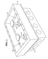
- Fig 1 illustrates a plinth 10, for the support of an attached object such as an ATM 12 (Fig 2).
- the plinth 10 has a fixing portion 14 for embedding into a secure foundation, such as a concrete base (not shown).
- a base plate 16 is arranged for support of the ATM 12, through support means 18.
- the support means 18 are arranged to crumple under an impact, of an excessive force, without the ATM 12 becoming detached from the plinth 10.
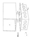
- the plinth 10 comprises flexible linkages 20, which are more clearly disclosed in Fig 2.
- the linkages are arranged for connection between the base plate 16 and the ATM 12.
- the linkages are formed from bendable rods, which are distinct from the support means 18.
- the linkages can be formed from other materials, such as universal joints or flexible wires, chains that are connectable to both the base plate 16 and the ATM 12 or other object to be supported.
- the support means 18 are metal sheets, such as sheet steel, arranged to support the object, when in use.
- the plinth 10 further comprises a foam release mechanism (not shown), which is arranged to inject foam into the interior space 22 defined by the base plate 16 and the sheet steel support means 18, when the plinth has been caused to crumple.
- a foam release mechanism (not shown), which is arranged to inject foam into the interior space 22 defined by the base plate 16 and the sheet steel support means 18, when the plinth has been caused to crumple.
- the interior space 22 can be filled with foam prior to use. This inhibits cutting tools, if they are used by criminals to try to cut the flexible linkages 20.
- the plinth is installed by embedding the portion 14 in concrete or other suitable material. Thereafter, the plinth 10 delays the removal of an ATM 12 or other object supported by a plinth because the plinth will crumple under the influence of a force, greater than a predetermined force, without the ATM or other object becoming detached from the plinth. In other words the ATM 12 will fall onto the floor whilst still attached to the plinth 10.
Landscapes
- Business, Economics & Management (AREA)
- Accounting & Taxation (AREA)
- Finance (AREA)
- Physics & Mathematics (AREA)
- General Physics & Mathematics (AREA)
- Fittings On The Vehicle Exterior For Carrying Loads, And Devices For Holding Or Mounting Articles (AREA)
- Working Measures On Existing Buildindgs (AREA)
- Forms Removed On Construction Sites Or Auxiliary Members Thereof (AREA)
- Vehicle Interior And Exterior Ornaments, Soundproofing, And Insulation (AREA)
Abstract
Description
- The present invention relates to a plinth for the support of a valuable object such as an Automated Teller Machine (ATM).
- ATMs that are not in through the wall locations, in banks and the like, are normally bolted directly to the ground through the safe.
- One of the main attacks on ATMs results from criminals using a truck or the like to ram the ATM. The force of the blow causes the ATM to shear from bolts. Lifting equipment is then used to load the ATM onto a flat bed truck, for removal from the premises. An alternative form of attack is to simply tie ropes around the ATM and pull it over, again shearing it from its bolts.
- Increasingly, ATMs employ ink-staining technology to deter criminals from stealing ATMs, as stained notes can be replaced at no cost to the ATM service providers. However, even if it is known that notes will have been stained, if the notes are not recovered then the ATM service provider will not have their cash replaced.
- Hence, it is an object of the present invention to prolong the time taken to remove an ATM from the scene of an attempted theft.
- According to a first aspect of the present invention there is provided a plinth, for the support of an attached object, the plinth having a fixing portion for embedding into a secure foundation, a base plate for support of the object, through support means which are arranged to crumple under an impact, without the object becoming detached from the plinth.
- Preferably, the plinth comprises flexible linkages that are arranged for connection between the base plate and the object to be supported.
- Preferably, the flexible linkages are distinct from the support means. Most preferably the flexible linkages take the form of bendable rods, universal joints, chains or flexible wires,that are connectable to both the base plate and the object to be supported.
- Preferably, the support means are metal sheets arranged to support the object, when in use. Most preferably, the support means are constructed from sheet steel.
- Most preferably, the support means are arranged to crumple under the impact of a substantial force. The force very much depends on the weight of the terminal. Under normal use the terminal is secure but with a sudden impact, such as a car hitting the terminal the plinth will deform, as described above.
- Preferably, the plinth comprises a foam release mechanism, arranged to inject foam into the interior space defined by the base plate and the support means, when the plinth has been caused to crumple.
- Alternatively, the interior space defined by the base plate and the support means is filled with foam prior to use.
- According to a second aspect of the present invention there is provided a method of delaying the removal of an object supported by a plinth as claimed in any preceding claim, the method including the steps of arranging that the plinth crumples under the influence of a force, without the object becoming detached from the plinth; and injecting foam into the interior of the base plate when the plinth has been caused to crumple, so as to jam any cutting tools used to attempt to cut the flexible linkages between the base plate and said object.
- An embodiment of the present invention will now be described, by way of example, with reference to the accompanying drawings, in which:
- Fig 1 is a schematic diagram of a plinth in accordance with the invention; and
- Fig 2; is a schematic diagram of the plinth of Fig 1, supporting an ATM, with the sheet steel support means of the plinth removed so as to more clearly illustrate the flexible linkages.
-
- Fig 1 illustrates a
plinth 10, for the support of an attached object such as an ATM 12 (Fig 2). Theplinth 10 has afixing portion 14 for embedding into a secure foundation, such as a concrete base (not shown). Abase plate 16 is arranged for support of theATM 12, through support means 18. The support means 18 are arranged to crumple under an impact, of an excessive force, without theATM 12 becoming detached from theplinth 10. - The
plinth 10 comprisesflexible linkages 20, which are more clearly disclosed in Fig 2. The linkages are arranged for connection between thebase plate 16 and theATM 12. In this embodiment the linkages are formed from bendable rods, which are distinct from the support means 18. - In other embodiments the linkages can be formed from other materials, such as universal joints or flexible wires, chains that are connectable to both the
base plate 16 and theATM 12 or other object to be supported. Also, the support means 18 are metal sheets, such as sheet steel, arranged to support the object, when in use. - The
plinth 10 further comprises a foam release mechanism (not shown), which is arranged to inject foam into theinterior space 22 defined by thebase plate 16 and the sheet steel support means 18, when the plinth has been caused to crumple. In an alternative embodiment theinterior space 22 can be filled with foam prior to use. This inhibits cutting tools, if they are used by criminals to try to cut theflexible linkages 20. - The plinth is installed by embedding the
portion 14 in concrete or other suitable material. Thereafter, theplinth 10 delays the removal of anATM 12 or other object supported by a plinth because the plinth will crumple under the influence of a force, greater than a predetermined force, without the ATM or other object becoming detached from the plinth. In other words theATM 12 will fall onto the floor whilst still attached to theplinth 10. - This means that criminals will have to take further action in order to detach the ATM, which is not necessary with conventional plinths as the connection between a conventional plinth and an ATM is sheared during by the force of the ram raider driving a vehicle into the plinth and ATM. In addition, the presence of foam in the
interior space 22 causes cutting tools to jam, if they are used in an attempt to severe the link between theplinth 10 and theATM 12, further increasing the time taken. - Modifications can be incorporated without departing from the scope of the present invention.
Claims (10)
- A plinth, for the support of an attached object, the plinth having a fixing portion for embedding into a secure foundation, a base plate for support of the object, through support means which are arranged to crumple under an impact, without the object becoming detached from the plinth.
- A plinth as claimed in claim 1, wherein the plinth comprises flexible linkages that are arranged for connection between the base plate and the object to be supported.
- A plinth as claimed in claim 2, wherein the flexible linkages are distinct from the support means.
- A plinth as claimed in any preceding claim, wherein the flexible linkages take the form of bendable rods, universal joints, chains or flexible wires, that are connectable to both the base plate and the object to be supported.
- A plinth as claimed in any preceding claim, wherein the support means are metal sheets arranged to support the object, when in use.
- A plinth as claimed in claim 5, wherein the support means are constructed from sheet steel.
- A plinth as claimed in any preceding claim wherein the support means are arranged to crumple under the impact which is used in attacks in ATMs, by driving a vehicle into the ATM and plinth.
- A plinth as claimed in any preceding claim, comprising a foam release mechanism, arranged to inject foam into the interior space defined by the base plate and the support means, when the plinth has been caused to crumple.
- A plinth as claimed in any of claims 1 to 7, wherein the interior space is filled with foam prior to use.
- A method of delaying the removal of an object supported by a plinth as claimed in any preceding claim, the method including the steps of arranging that the plinth crumples under the influence of a force,without the object becoming detached from the plinth; and injecting foam into the interior of the base plate when the plinth has been caused to crumple, so as to jam any cutting tools used to attempt to cut the flexible linkages between the base plate and said object.
Applications Claiming Priority (2)
| Application Number | Priority Date | Filing Date | Title |
|---|---|---|---|
| GBGB0406746.8A GB0406746D0 (en) | 2004-03-25 | 2004-03-25 | Anti-ram raid plinth |
| GB0406746 | 2004-03-25 |
Publications (2)
| Publication Number | Publication Date |
|---|---|
| EP1580703A1 true EP1580703A1 (en) | 2005-09-28 |
| EP1580703B1 EP1580703B1 (en) | 2016-09-28 |
Family
ID=32188696
Family Applications (1)
| Application Number | Title | Priority Date | Filing Date |
|---|---|---|---|
| EP05250956.9A Expired - Lifetime EP1580703B1 (en) | 2004-03-25 | 2005-02-19 | Anti-ram raid plinth |
Country Status (3)
| Country | Link |
|---|---|
| US (1) | US7427054B2 (en) |
| EP (1) | EP1580703B1 (en) |
| GB (1) | GB0406746D0 (en) |
Cited By (1)
| Publication number | Priority date | Publication date | Assignee | Title |
|---|---|---|---|---|
| IT202000012358A1 (en) * | 2020-05-26 | 2021-11-26 | M I B S R L | BASE FOR BANCOMAT, ATM AND SIMILAR SAFE |
Families Citing this family (3)
| Publication number | Priority date | Publication date | Assignee | Title |
|---|---|---|---|---|
| US8485113B2 (en) * | 2011-06-29 | 2013-07-16 | Pssi International, Inc. | Universal security plate for automatic teller machines |
| AR113952A1 (en) * | 2018-01-03 | 2020-07-01 | Tecnologia Bancaria Sa | DEVICE TO ANCHOR AND PROTECT SELF-SERVICE TERMINALS AND BOXES IN GENERAL |
| CN113483159A (en) * | 2021-06-16 | 2021-10-08 | Tcl华星光电技术有限公司 | Pipeline support and sputtering vacuum pipeline |
Citations (7)
| Publication number | Priority date | Publication date | Assignee | Title |
|---|---|---|---|---|
| US4950522A (en) * | 1985-12-24 | 1990-08-21 | Ford Motor Company | Plastic construction member for a motor vehicle |
| GB2268541A (en) * | 1992-07-03 | 1994-01-12 | Acketts Plc | Anti-theft device. |
| GB2273528A (en) * | 1992-12-15 | 1994-06-22 | Kitchin Eng Ltd | Security device |
| GB2288200A (en) * | 1994-04-05 | 1995-10-11 | Derek Sydney Stephens | Anti-ram raiding device |
| GB2299619A (en) * | 1995-04-07 | 1996-10-09 | Acketts Group Ltd | Anti-theft device for ATM |
| US6266930B1 (en) * | 1999-05-12 | 2001-07-31 | Fujitsu Limited | Safeguard structure and transaction device |
| FR2820165A1 (en) * | 2001-01-31 | 2002-08-02 | Cs Systemes De Securite C3S | Anti-theft device for use with cash dispenser machine to prevent it from being torn out by driving of a motor vehicle into it, through use of impact absorbing elements |
Family Cites Families (3)
| Publication number | Priority date | Publication date | Assignee | Title |
|---|---|---|---|---|
| GB2366325B (en) | 2000-08-30 | 2004-07-21 | Acketts Group Ltd | Anti-theft device |
| WO2003103451A1 (en) * | 2002-06-05 | 2003-12-18 | Acketts Group Limited | Plinth for automated teller machine |
| US20060056921A1 (en) * | 2004-08-30 | 2006-03-16 | Simmons Robert J | Slab-embedded precision height-and-tilt-adjustable plinth anchoring for a column base |
-
2004
- 2004-03-25 GB GBGB0406746.8A patent/GB0406746D0/en not_active Ceased
-
2005
- 2005-02-19 EP EP05250956.9A patent/EP1580703B1/en not_active Expired - Lifetime
- 2005-03-24 US US11/089,206 patent/US7427054B2/en not_active Expired - Lifetime
Patent Citations (7)
| Publication number | Priority date | Publication date | Assignee | Title |
|---|---|---|---|---|
| US4950522A (en) * | 1985-12-24 | 1990-08-21 | Ford Motor Company | Plastic construction member for a motor vehicle |
| GB2268541A (en) * | 1992-07-03 | 1994-01-12 | Acketts Plc | Anti-theft device. |
| GB2273528A (en) * | 1992-12-15 | 1994-06-22 | Kitchin Eng Ltd | Security device |
| GB2288200A (en) * | 1994-04-05 | 1995-10-11 | Derek Sydney Stephens | Anti-ram raiding device |
| GB2299619A (en) * | 1995-04-07 | 1996-10-09 | Acketts Group Ltd | Anti-theft device for ATM |
| US6266930B1 (en) * | 1999-05-12 | 2001-07-31 | Fujitsu Limited | Safeguard structure and transaction device |
| FR2820165A1 (en) * | 2001-01-31 | 2002-08-02 | Cs Systemes De Securite C3S | Anti-theft device for use with cash dispenser machine to prevent it from being torn out by driving of a motor vehicle into it, through use of impact absorbing elements |
Non-Patent Citations (2)
| Title |
|---|
| ATM SECURITY WORKING GROUP: ""STAND-ALONE" ATM'S: RECOMMENDED SECURITY GUIDELINES", INTERNET ARTICLE, September 2002 (2002-09-01), XP002329896, Retrieved from the Internet <URL:http://www.atmianortham.com/pdf/stand_alone.pdf> [retrieved on 20050530] * |
| SCOTIA SECURITY GROUP: "Banking Solutions DS20 ATM Stand", INTERNET ARTICLE, 11 October 2004 (2004-10-11), XP002329897, Retrieved from the Internet <URL:http://www.scotia.co.uk/pdfs/DS20%20A4.pdf> [retrieved on 20050530] * |
Cited By (1)
| Publication number | Priority date | Publication date | Assignee | Title |
|---|---|---|---|---|
| IT202000012358A1 (en) * | 2020-05-26 | 2021-11-26 | M I B S R L | BASE FOR BANCOMAT, ATM AND SIMILAR SAFE |
Also Published As
| Publication number | Publication date |
|---|---|
| GB0406746D0 (en) | 2004-04-28 |
| EP1580703B1 (en) | 2016-09-28 |
| US7427054B2 (en) | 2008-09-23 |
| US20050224688A1 (en) | 2005-10-13 |
Similar Documents
| Publication | Publication Date | Title |
|---|---|---|
| EP1147261B1 (en) | Breakaway support post for highway guardrail end treatment. | |
| US5762443A (en) | Ground retractable automobile barrier | |
| US10233601B2 (en) | Crash barrier | |
| EP1733095B1 (en) | Net and mat | |
| AU2007222896B2 (en) | Assemblies and method for securing surface mounted articles to accommodate applied loads | |
| JP2007513822A (en) | Energy absorption system with support | |
| US7083357B2 (en) | Retractable wide-span vehicle barrier system | |
| EP1365070A1 (en) | Breakaway support post for highway guardrail end treatments | |
| US20010048101A1 (en) | Apparatus and methods for strengthening guardrail installations | |
| US7794172B2 (en) | Perimeter anti-ram system | |
| EP1580703B1 (en) | Anti-ram raid plinth | |
| US10746345B2 (en) | Device for anchoring and protecting self-service terminals and vaults in general | |
| US11578468B1 (en) | Anti-ram crash-rated bollard | |
| GB2297803A (en) | Anti-theft device for ATM | |
| US11830328B2 (en) | Secure safe apparatus and system | |
| CN105905465A (en) | Method and device for weakening impact of stone on front wall of storage bin | |
| US20060091371A1 (en) | CNC impact load deflector sleeve and removable collar for cable and post protection | |
| EP0674742A1 (en) | Security device | |
| KR101779318B1 (en) | Roof moving device for Waste transport truck | |
| WO2007071725A1 (en) | Anti-vehicle barrier | |
| CN214691101U (en) | A kind of porcelain soil silo feeding safety protection frame | |
| CN213681883U (en) | Collision-proof guardrail for road | |
| CN211523019U (en) | Highway guardrail structure | |
| GB2589516A (en) | Street furniture apparatus | |
| McCallen et al. | Evaluation of an Expedient Terrorist Vehicle Barrier |
Legal Events
| Date | Code | Title | Description |
|---|---|---|---|
| PUAI | Public reference made under article 153(3) epc to a published international application that has entered the european phase |
Free format text: ORIGINAL CODE: 0009012 |
|
| AK | Designated contracting states |
Kind code of ref document: A1 Designated state(s): AT BE BG CH CY CZ DE DK EE ES FI FR GB GR HU IE IS IT LI LT LU MC NL PL PT RO SE SI SK TR |
|
| AX | Request for extension of the european patent |
Extension state: AL BA HR LV MK YU |
|
| 17P | Request for examination filed |
Effective date: 20060328 |
|
| AKX | Designation fees paid |
Designated state(s): DE ES FR GB IT |
|
| 17Q | First examination report despatched |
Effective date: 20060803 |
|
| RAP1 | Party data changed (applicant data changed or rights of an application transferred) |
Owner name: NCR INTERNATIONAL, INC. |
|
| GRAP | Despatch of communication of intention to grant a patent |
Free format text: ORIGINAL CODE: EPIDOSNIGR1 |
|
| INTG | Intention to grant announced |
Effective date: 20160713 |
|
| GRAS | Grant fee paid |
Free format text: ORIGINAL CODE: EPIDOSNIGR3 |
|
| GRAA | (expected) grant |
Free format text: ORIGINAL CODE: 0009210 |
|
| AK | Designated contracting states |
Kind code of ref document: B1 Designated state(s): DE ES FR GB IT |
|
| REG | Reference to a national code |
Ref country code: GB Ref legal event code: FG4D |
|
| REG | Reference to a national code |
Ref country code: DE Ref legal event code: R084 Ref document number: 602005050299 Country of ref document: DE |
|
| REG | Reference to a national code |
Ref country code: DE Ref legal event code: R096 Ref document number: 602005050299 Country of ref document: DE |
|
| REG | Reference to a national code |
Ref country code: GB Ref legal event code: 746 Effective date: 20161013 |
|
| REG | Reference to a national code |
Ref country code: FR Ref legal event code: PLFP Year of fee payment: 13 |
|
| PG25 | Lapsed in a contracting state [announced via postgrant information from national office to epo] |
Ref country code: ES Free format text: LAPSE BECAUSE OF FAILURE TO SUBMIT A TRANSLATION OF THE DESCRIPTION OR TO PAY THE FEE WITHIN THE PRESCRIBED TIME-LIMIT Effective date: 20160928 |
|
| REG | Reference to a national code |
Ref country code: DE Ref legal event code: R097 Ref document number: 602005050299 Country of ref document: DE |
|
| PG25 | Lapsed in a contracting state [announced via postgrant information from national office to epo] |
Ref country code: IT Free format text: LAPSE BECAUSE OF FAILURE TO SUBMIT A TRANSLATION OF THE DESCRIPTION OR TO PAY THE FEE WITHIN THE PRESCRIBED TIME-LIMIT Effective date: 20160928 |
|
| PLBE | No opposition filed within time limit |
Free format text: ORIGINAL CODE: 0009261 |
|
| STAA | Information on the status of an ep patent application or granted ep patent |
Free format text: STATUS: NO OPPOSITION FILED WITHIN TIME LIMIT |
|
| 26N | No opposition filed |
Effective date: 20170629 |
|
| REG | Reference to a national code |
Ref country code: FR Ref legal event code: PLFP Year of fee payment: 14 |
|
| P01 | Opt-out of the competence of the unified patent court (upc) registered |
Effective date: 20230512 |
|
| PGFP | Annual fee paid to national office [announced via postgrant information from national office to epo] |
Ref country code: DE Payment date: 20240228 Year of fee payment: 20 Ref country code: GB Payment date: 20240227 Year of fee payment: 20 |
|
| PGFP | Annual fee paid to national office [announced via postgrant information from national office to epo] |
Ref country code: FR Payment date: 20240226 Year of fee payment: 20 |
|
| REG | Reference to a national code |
Ref country code: DE Ref legal event code: R071 Ref document number: 602005050299 Country of ref document: DE |
|
| REG | Reference to a national code |
Ref country code: GB Ref legal event code: PE20 Expiry date: 20250218 |
|
| PG25 | Lapsed in a contracting state [announced via postgrant information from national office to epo] |
Ref country code: GB Free format text: LAPSE BECAUSE OF EXPIRATION OF PROTECTION Effective date: 20250218 |