FIELD OF THE INVENTION
The present invention relates to a process of preparing
a planographic printing plate.
BACKGROUND OF THE INVENTION
Hitherto, an image formation method has been carried
out in a conventional photographic plate making, which
comprises bringing a light sensitive planographic printing
plate material into contact with an original with an image,
and exposing to light through the original. Recently, a
computer to plate (hereinafter referred as to CTP) system has
spread which comprises recording directly a digital image
onto a light sensitive planographic printing plate material
employing a laser. However, in order to carry out scanning
exposure in a short time employing a laser, not only a laser
with high output power but a light sensitive planographic
printing plate material for CTP having sensitivity of 1,000
to 10,000 times the sensitivity of a conventional contact
exposure type light sensitive planographic printing plate
material are required. A planographic printing plate
material for CTP with such a high sensitivity is expensive,
and has problem in that sensitivity varies after long term
storage.
A method is proposed in which digital signals are
recorded on a light sensitive planographic printing plate
material employing an ultraviolet lamp as a light source.
This method is advantageous in view of cost reduction, since
it is possible to use a conventional contact exposure type
light sensitive planographic printing plate material having
sensitivity in ultraviolet regions. However, this method has
problem that exposure time takes several times that in a
conventional contact exposure. Thus, a light sensitive
planographic printing plate material is required which has
high sensitivity in the ultraviolet regions.
In Japanese Patent O.P.I. Publication No. 2004-29296 is
disclosed a method of preparing a printing plate from a
planographic printing plate material comprising a hydrophilic
support and an image formation layer containing a
polymerizable ethylenically unsaturated compound, a
photopolymerization initiator, and a sensitizing dye having a
specific structure, the method comprising the step of
exposing the planographic printing plate material to
ultraviolet rays corresponding to image data employing a DMD
to polymerize the polymerizable ethylenically unsaturated
compound. A printing plate prepared according to this method
provides high printing durability, but has problem in
printing durability. In Japanese Patent O.P.I. Publication
No. 2004-20623 is disclosed a method of preparing a printing
plate from a planographic printing plate material comprising
a curable resin, the method comprising the step of exposing
the planographic printing plate material to ultraviolet rays
corresponding to image data employing a DMD, while heating,
wherein curable resin at exposed portions are cured. This
method provides a printing plate high printing durability,
but has problem in that a heating system for heating the
planographic printing plate material is complicate and
impracticable, and the heating temperature is difficult to
control, resulting in instability of image forming
conditions. Further, a printing plate prepared according to
this method has poor chemical resistance, and has problem in
that when in a printing process ink stains at the non-image
portions are removed employing a cleaning solution, so-called
a plate cleaner, image portions, particularly small dots are
likely to disappear.
SUMMARY OF THE INVENTION
In view of the above, the present invention has been
made. An object of the invention is to provide a process of
preparing, in a short time, a planographic printing plate
with high chemical resistance and high printing durability
from a planographic printing plate material, employing a
digital mirror device (DMD) in a CTP system.
BRIEF DESCRIPTION OF THE DRAWING
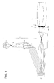
Fig. 1 shows a schematic view of a fundamental
structure of an exposure device employing DMD.
DETAILED DESCRIPTION OF THE INVENTION
The above object has been attained by one of the
following constitutions:
Next, the present invention will be explained in
detail.
In view of the above, the present inventor has made an
extensive study. As a result, the present inventor has found
a process of preparing, from a light sensitive planographic
printing plate material, a planographic printing plate with
high chemical resistance and high printing durability in a
short time, employing an exposure device comprising a digital
mirror device (DMD) in a CTP system, and completed the
invention. The process comprises the steps of imagewise
exposing the light sensitive planographic printing plate
material employing an exposure device comprising a DMD, and
removing an image formation layer at non-exposed portions
with an aqueous alkali solution to form an image, the light
sensitive planographic printing plate material comprising a
hydrophilic support and provided thereon, an image formation
layer containing (A) at least one polymerization initiator
selected from an arene-iron complex a-1 and a tribromoacetyl
compound a-2, (B) a polymerizable ethylenically unsaturated
compound and (C) an alkali soluble resin with an acid value
of 5 to 200.
The present invention will be detailed below.
The light sensitive planographic printing plate
material in the invention comprises an image formation layer
containing (A) at least one polymerization initiator selected
from an arene-iron complex a-1 and a tribromoacetyl compound
a-2, (B) a polymerizable ethylenically unsaturated compound
and (C) an alkali soluble resin.
[Polymerization initiator]
The polymerization initiator in the invention will be
detailed below.
The image formation layer in the invention contains at
least one polymerization initiator selected from an iron-arene
complex and a tribromoacetyl compound.
Iron-arene complex a-1
As the iron-arene complex used in the invention, there
are those disclosed in Japanese Patent O.P.I. Publication
Nos. 59-219307. Preferred examples of the iron-arene complex
include η-benzene-(η-cyclopentadienyl)iron
hexafluorophosphate, η-cumene-(η-cyclopentadienyl)iron
hexafluorophosphate, η-fluorene-(η-cyclopentadienyl)iron
hexafluorophosphate, η-naphthalene-(η-cyclopentadienyl)iron
hexafluorophosphate, η-xylene- (η-cyclopentadienyl) iron
hexafluorophosphate, and η-benzene-(η-cyclopentadienyl)iron
tetrafluoroborate.
Tribromoacetyl compound a-2
As the tribromoacetyl compound used in the invention,
there are for example, tribromoacetoaldehyde, tribromoacetic
acid, tribromoacetophenone, tribromoacetylthiophene, a
tribromoacetate compound obtained by reacting alcohols with
tribromoacetyl chloride, and a tribromoacetamide compound
obtained by reacting amines with tribromoacetyl chloride.
Examples of the tribromoacetyl compound will be listed
below, but the invention is not limited thereto.
The content of the iron-arene complex a-1 or
tribromoacetyl compound a-2 in the image formation layer is
preferably from 1 to 20% by weight. When these two
polymerization initiators are used, each is contained in an
amount of preferably from 1 to 20% by weight in the image
formation layer.
(Other polymerization initiators)
The image formation layer in the invention can contain
other photopolymerization initiators together with the
hexaarylbisimidazole compound or diazo resin in the
invention.
Examples of the other photopolymerization initiators
include radical generating compounds disclosed in Japanese
Patent Publication No. 2002-537419, polymerization initiators
disclosed in Japanese Patent O.P.I. Publication Nos. 2001-175006,
2002-278057, and 2003-5363, onium salts having two or
more cation portions in the molecule disclosed in Japanese
Patent O.P.I. Publication No. 2003-76010, N-nitroso amine
compounds disclosed in Japanese Patent O.P.I. Publication No.
2001-133966, thermally radical generating compounds disclosed
in Japanese Patent O.P.I. Publication No. 2001-343742,
compounds of generating a radical or an acid by heat
disclosed in Japanese Patent O.P.I. Publication No. 2002-6482,
borate compounds disclosed in Japanese Patent O.P.I.
Publication No. 2002-116539, compounds of generating a
radical or an acid by heat disclosed in Japanese Patent
O.P.I. Publication No. 2002-148790, photopolymerization
initiators or thermal polymerization initiators each having a
polymerizable unsaturated group disclosed in Japanese Patent
O.P.I. Publication No. 2002-207293, onium salts having, as a
counter ion, a divalent or more valent anion disclosed in
Japanese Patent O.P.I. Publication No. 2002-268217,
sulfonylsulfone compounds having a specific structure
disclosed in Japanese Patent O.P.I. Publication No. 2002-328465,
thermally radical generating compounds disclosed in
Japanese Patent O.P.I. Publication No. 2002-341519, and
hexaarylbisimidazole compounds disclosed in Japanese Patent
O.P.I. Publication Nos. 2002-295426.
Preferred examples of the other photopolymerization
initiators include a triarylsulfonium salt, a diaryliodonium
salt, a titanocene compound, a trihalomethyltriazine
compound, an acylphosphine oxide compound, a benzoin
derivative, or an N-phenylglycine derivative, and are not
limited thereto.
Diazo resins, for example, those disclosed in Japanese
Patent O.P.I. Publication No. 10-313017, can be preferably
used as the other polymerization initiator.
The content of the other photopolymerization initiator
in the image formation layer, which can be used in
combination with polymerization initiators (a-1) or (a-2), is
not specifically limited, but is preferably from 0.1 to 20%
by weight, and more preferably from 0.8 to 15% by weight.
[Sensitizing dye]
The image formation layer in the invention can contain
a sensitizing dye in order to accelerate polymerization.
Since ultraviolet rays are used as light for recording an
image, a sensitizing dye absorbing the ultraviolet rays is
preferred. Typically, a sensitizing dye is preferred which
has an absorption maximum at wavelength regions of from 350
to 450 nm, and more preferably from 350 to 410 nm.
Examples thereof include optical whitening dyes
disclosed in Japanese Patent O.P.I. Publication No. 2003-295426,
sensitizing dyes disclosed in Japanese Patent O.P.I.
Publication No. 2003-21901, compounds represented by formula
(I) disclosed in Japanese Patent O.P.I. Publication No. 2003-21895,
compounds represented by formula (I) disclosed in
Japanese Patent O.P.I. Publication No. 2003-21894,
sensitizing dyes having a specific chemical structure
disclosed in Japanese Patent O.P.I. Publication No. 2003-351702,
sensitizing dyes having a specific chemical structure
disclosed in Japanese Patent O.P.I. Publication No. 2003-351701,
sensitizing dyes having a specific chemical structure
(a pyrrolopyrrole ring) disclosed in Japanese Patent O.P.I.
Publication No. 2003-351065, sensitizing dyes disclosed in
Japanese Patent O.P.I. Publication Nos. 2002-268239, and
2002-268204, compounds represented by formula (I) disclosed
in Japanese Patent O.P.I. Publication No. 2002-221790,
compounds represented by formula (I) disclosed in Japanese
Patent O.P.I. Publication No. 2002-202598, carbazole type
sensitizing dyes disclosed in Japanese Patent O.P.I.
Publication No. 2001-042524, sensitizing dyes disclosed in
Japanese Patent O.P.I. Publication Nos. 2000-309724 and 2000-258910,
naphtho[1,8-bc]furan-5-on derivatives disclosed in
Japanese Patent O.P.I. Publication Nos. 2000-206690,
merocyanine dyes disclosed in Japanese Patent O.P.I.
Publication Nos. 2000-147763, and carbonyl compounds
disclosed in Japanese Patent O.P.I. Publication Nos. 2000-098605.
Preferred examples of the sensitizing dye include
coumarin compounds represented by formulas Dye 01 through 08
below, merocyanine dyes represented by formulas Dye 09
through 11 below, boron-contained compounds represented by
formulas Dye 12 through 14 below, styryl dyes represented by
formulas Dye 15 and 16 below, pyrylium salts represented by
formulas Dye 17 and 18 below, and cyanine dyes represented by
formulas Dye 19 through 24 below. Dyes 01 through 24 are
listed below. The present invention is not limited thereto.
The content of the sensitizing dye in image formation
layer is not specifically limited, but is preferably from 0.1
to 20% by weight, and more preferably from 0.8 to 15% by
weight. The content of the sensitizing dye is a content
providing an absorbance of preferably from 0.2 to 2.0, and
more preferably from 0.3 to 1.2 in the reflection spectrum
measured employing an integrating sphere. These sensitizing
dyes can be used singly or in combination.
[Polymerizable ethylenically unsaturated compound]
In the invention, the image formation layer can contain
a polymerizable ethylenically unsaturated compound, so-called
a monomer or a polyfunctional oligomer. The content of the
monomer or polyfunctional oligomer in the image formation
layer is preferably from 10 to 70% by weight, and more
preferably from 20 to 60% by weight.
As the monomer or polyfunctional oligomer, there are a
conventional radical polymerizable monomer, and a
polyfunctional monomer or oligomer having two or more of an
ethylenic double bond in the molecule as generally used in an
ultraviolet curable resin composition.
The monomer or polyfunctional oligomer is not
specifically limited. Preferred examples thereof include a
monofunctional acrylate such as 2-ethylhexyl acrylate, 2-hydroxypropyl
acrylate, glycerol acrylate, tetrahydrofurfuryl
acrylate, phenoxyethyl acrylate, nonylphenoxyethyl acrylate,
tetrahydrofurfuryl-oxyethyl acrylate,
tetrahydrofurfuryloxyhexanorideacrylate, an ester of 1,3-dioxane-ε-caprolactone
adduct with acrylic acid, or 1,3-dioxolane
acrylate; a methacrylate, itaconate, crotonate or
maleate alternative of the above acrylate; a bifunctional
acrylate such as ethyleneglycol diacrylate, triethyleneglycol
diacrylate, pentaerythritol diacrylate, hydroquinone
diacrylate, resorcin diacrylate, hexanediol diacrylate,
neopentyl glycol diacrylate, tripropylene glycol diacrylate,
hydroxypivalic acid neopentyl glycol diacrylate, neopentyl
glycol adipate diacrylate, diacrylate of hydroxypivalic acid
neopentyl glycol-ε-caprolactone adduct, 2-(2-hydroxy-1,1-dimethylethyl)-5-hydroxymethyl-5-ethyl-1,3-dioxane
diacrylate, tricyclodecanedimethylol acrylate,
tricyclodecanedimethylol acrylate-ε-caprolactone adduct or
1,6-hexanediol diglycidylether diacrylate; a dimethacrylate,
diitaconate, dicrotonate or dimaleate alternative of the
above diacrylate; a polyfunctional acrylate such as
trimethylolpropane triacrylate, ditrimethylolpropane
tetraacrylate, trimethylolethane triacrylate, pentaerythritol
triacrylate, pentaerythritol tetraacrylate, dipentaerythritol
tetraacrylate, dipentaerythritol pentaacrylate,
dipentaerythritol hexacrylate, dipentaerythritol hexacrylate-ε-caprolactone
adduct, pyrrogallol triacrylate, propionic
acid dipentaerythritol triacrylate, propionic acid
dipentaerythritol tetraacrylate or hydroxypivalylaldehyde
modified dimethylolpropane triacrylate; a methacrylate,
itaconate, crotonate or maleate alternative of the above
polyfunctional acrylate.
Prepolymers can be used, and examples thereof include
prepolymers described later. These prepolymers can be used
singly, in combination, or as an admixture thereof with the
above described monomer and/or oligomer.
Examples of the prepolymer include polyester
(meth)acrylate obtained by incorporating (meth)acrylic acid
in a polyester of a polybasic acid such as adipic acid,
trimellitic acid, maleic acid, phthalic acid, terephthalic
acid, hymic acid, malonic acid, succinic acid, glutaric acid,
itaconic acid, pyromellitic acid, fumalic acid, pimelic acid,
sebatic acid, dodecanic acid or tetrahydrophthalic acid with
a polyol such as ethylene glycol, ethylene glycol, diethylene
glycol, propylene oxide, 1,4-butane diol, triethylene glycol,
tetraethylene glycol, polyethylene glycol, grycerin,
trimethylol propane, pentaerythritol, sorbitol, 1,6-hexanediol
or 1,2,6-hexanetriol; an epoxyacrylate such as
bisphenol A·epichlorhydrin·(meth)acrylic acid or phenol
novolak·epichlorhydrin·(meth)acrylic acid obtained by
incorporating (meth)acrylic acid in an epoxy resin; an
urethaneacrylate such as ethylene glycol·adipic
acid·tolylenediisocyanate·2-hydroxyethylacrylate,
polyethylene glycol·tolylenediisocyanate·2-hydroxyethylacrylate,
hydroxyethylphthalyl
methacrylate·xylenediisocyanate, 1,2-polybutadieneglycol·tolylenediisocyanate·2-hydroxyethylacrylate
or trimethylolpropane·propylene
glycol·tolylenediisocyanate·2-hydroxyethylacrylate, obtained
by incorporating (meth)acrylic acid in an urethane resin; a
silicone acrylate such as polysiloxane acrylate, or
polysiloxane·diisocyanate·2-hydroxyethylacrylate; an alkyd
modified acrylate obtained by incorporating a methacroyl
group in an oil modified alkyd resin; and a spirane resin
acrylate.
The image formation layer in the invention may contain
a monomer such as a phosphazene monomer, triethylene glycol
di(meth)acrylate , an EO modified isocyanuric acid
diacrylate, an EO modified isocyanuric acid triacrylate,
dimethyloltricyclodecane diacrylate, trimethylolpropane
acrylate benzoate, an alkylene glycol acrylate, or a urethane
modified acrylate, or an addition polymerizable oligomer or
prepolymer having a structural unit derived from the above
monomer.
The ethylenic monomer used in the invention is a
phosphate compound having at least one (meth)acryloyl group.
The phosphate compound is a compound having a (meth)acryloyl
group in which at least one hydroxyl group of phosphoric acid
is esterified.
Besides the above compounds, compounds disclosed in
Japanese Patent O.P.I. Publication Nos. 58-212994, 61-6649,
62-46688, 62-48589, 62-173295, 62-187092, 63-67189, and 1-244891,
compounds described on pages 286 to 294 of "11290
Chemical Compounds" edited by Kagakukogyo Nipposha, and
compounds described on pages 11 to 65 of "UV·EB Koka Handbook
(Materials)" edited by Kobunshi Kankokai can be suitably
used. Of these compounds, compounds having two or more acryl
or methacryl groups in the molecule are preferable, and those
having a molecular weight of not more than 10,000, and
preferably not more than 5,000 are more preferable.
In the invention, an addition polymerizable
ethylenically unsaturated monomer having a tertiary amino
group in the molecule is preferably used as the polymerizable
ethylenically unsaturated compound. Its molecular structure
is not limited, but those are preferred in which a tertiary
amine having a hydroxyl group is modified with glycidyl
methacrylate, methacrylic chloride, or acrylic chloride.
Examples thereof include a polymerizable compound disclosed
in Japanese Patent O.P.I. Publication Nos. 1-165613, and
Japanese Patent Publication Nos. 1-203413 and 1-197213.
A reaction product of (i) a polyhydric alcohol having a
tertiary amino group in the molecule, (ii) a diisocyanate,
and (iii) a compound having both hydroxyl group and addition
polymerizable ethylenically double bond in the molecule is
preferably used in the invention. Examples of the polyhydric
alcohol having a tertiary amino group in the molecule include
triethanolamine, N-methyldiethanolamine, N-ethyldiethanolamine,
N-ethyldiethanolamine, N-n-butyldiethanolamine,
N-tert-butyldiethanolamine, N,N-di(hydroxyethyl)aniline,
N,N, N', N'-tetra-2-hydroxypropylethylenediamine,
p-tolyldiethanolamine, N,N, N',
N'-tetra-2-hydroxyethylethylenediamine, N,N-bis(2-hydroxypropyl)aniline,
allyldiethanolamine, 3-dimethylamino-1,2-propane
diol, 3-diethylamino-1,2-propane diol, N,N-di(n-propylamino)-2,3-propane
diol, N,N-di(iso-propylamino)-2,3-propane
diol, and 3-(N-methyl-N-benzylamino)-1,2-propane
diol.
Examples of the diisocyanate include butane-1,4-diisocyanate,
hexane-1,6-diisocyanate, 2-methylpentane-1,5-diisocyanate,
octane-1,8-diisocyanate, 1,3-diisocyanatomethylcyclohexanone,
2,2,4-trimethylhexane-1,6-diisocyanate,
isophorone diisocyanate, 1,2-phenylene
diisocyanate, 1,3-phenylene diisocyanate, 1,4-phenylene
diisocyanate, tolylene-2,4-diisocyanate, tolylene-2,5-diisocyanate,
tolylene-2,6-diisocyanate, 1,3-di(isocyanatomethyl)benzene,
and 1,3-bis(1-isocyanato-1-methylethyl)benzene,
but the invention is not specifically
limited thereto. Examples of the compound having a hydroxyl
group and an addition polymerizable ethylenically double bond
in the molecule include compounds MH-1 through MH-13 as
described later.
The chemical structure of MH-1 through MH-13 will be
shown below.
Preferred examples thereof include 2-hydroxyethyl
methacrylate, 2-hydroxyethyl acrylate, 4-hydroxybutyl
acrylate, 2-hydroxypropylene-1,3-dimethacrylate, and 2-hydroxypropylene-1-methacrylate-3-acrylate.
The reaction product above can be synthesized according
to the same method as a conventional method in which a
urethaneacrylate compound is ordinarily synthesized employing
an ordinary diol, a diisocyanate and an acrylate having a
hydroxyl group.
Examples of the reaction product of a polyhydric
alcohol having a tertiary amino group in the molecule, a
diisocyanate and a compound having a hydroxyl group and an
addition polymerizable ethylenically double bond in the
molecule will be listed below.
In addition to the above, acrylates or methacrylates
disclosed in Japanese Patent O.P.I. Publication Nos. 1-105238
and 2-127404 can be used.
[Alkali soluble resin as binder]
The image formation layer in the invention contains an
alkali soluble resin as a binder. The weight average
molecular weight of the alkali soluble resin in the invention
is not specifically limited, but is in the range of from
preferably 5,000 to 200,000, and more preferably from
preferably 10,000 to 100,000. The alkali soluble resin in
the invention has an acid value of preferably from 5 to 200,
more preferably from 10 to 150, and most preferably 10 to
120.
As the alkali soluble resin in the invention can be
used a polyacrylate resin, a polyurethane resin, a polyamide
resin, a polyester resin, an epoxy resin, a phenol resin, a
polycarbonate resin, a polyvinyl butyral resin, a polyvinyl
formal resin, a shellac resin, or another natural resin.
These resins can be used singly or as an admixture of two or
more thereof.
The alkali soluble resin in the invention is preferably
a copolymer obtained by copolymerization of an acryl or
methacryl monomer with another monomer, and more preferably a
copolymer containing (a) a carboxyl group-containing monomer
unit and (b) an alkyl methacrylate or alkyl acrylate unit as
the copolymerization component.
Examples of the carboxyl group-containing monomer
include an α, β-unsaturated carboxylic acid, for example,
acrylic acid, methacrylic acid, maleic acid, maleic
anhydride, itaconic acid, itaconic anhydride or a carboxylic
acid such as a half ester of phthalic acid with 2-hydroxyethyl
methacrylate.
Examples of the alkyl methacrylate or alkyl acrylate
include an unsubstituted alkyl ester such as
methylmethacrylate, ethylmethacrylate, propylmethacrylate,
butylmethacrylate, amylmethacrylate, hexylmethacrylate,
heptylmethacrylate, octylmethacrylate, nonylmethacrylate,
decylmethacrylate, undecylmethacrylate, dodecylmethacrylate,
methylacrylate, ethylacrylate, propylacrylate, butylacrylate,
amylacrylate, hexylacrylate, heptylacrylate, octylacrylate,
nonylacrylate, decylacrylate, undecylacrylate, or
dodecylacrylate; a cyclic alkyl ester such as cyclohexyl
methacrylate or cyclohexyl acrylate; and a substituted alkyl
ester such as benzyl methacrylate, 2-chloroethyl
methacrylate, N,N-dimethylaminoethyl methacrylate, glycidyl
methacrylate, benzyl acrylate, 2-chloroethyl acrylate or N,N-dimethylaminoethyl
acrylate.
The copolymer described above can further contain
another comonomer unit.
Examples of such a comonomer include monomers described
in the following items (1) through (14).
The copolymer above can be prepared by a conventional
solution polymerization, a bulk polymerization or an emulsion
polymerization. The polymerization initiators used are not
specifically limited, and include 2,2'-azobisisobutyronitrile
(AIBN), and 2,2'-azobis(2-methylbutyronitrile). The
polymerization initiator is used in an amount of from 0.05 to
10.0 parts by weight, and preferably from 0.1 to 5 parts by
weight, based on 100 parts by weight of the total monomer
used in polymerization. As the solvents used in the solution
polymerization, there are organic solvents of ketone type,
ester type or aromatic hydrocarbon type. Examples thereof
include toluene, ethyl acetate, benzene, methylcellosolve,
ethylcellosolve, acetone, and methyl ethyl ketone, which are
good solvents for (meth)acryl polymers. Among these,
solvents with a boiling point of from 60 to 120°C are
preferred. Solution polymerization is carried out at a
temperature of from 40 to 120 °C, and preferably from 60 to
110 °C for 3 to 10 hours, preferably 5 to 8 hours. After the
polymerization is completed in the solution polymerization to
obtain a polymer solution, the solvents in the polymer
solution are removed to obtain a polymer. The polymer
solution can be used without removing the solvents for the
subsequent incorporation reaction of a double bond described
later.
The molecular weight of the polymer can be controlled
by kinds of solvents used or polymerization temperature. The
polymerization solvents used or polymerization temperature
for preparing a polymer having an intended molecular weight
can be suitably determined due to kinds of monomers used.
The molecular weight of the polymer can be controlled by
addition of a specific organic solvent to the polymerization
solvents. Examples of the specific solvent include
mercaptans such as n-octylmercaptan, n-dodecylmercaptan, t-dodecylmercaptan,
and mercaptoethanol; and chlorine-containing
solvents such as carbon tetrachloride, butyl
chloride, and propylene chloride. A mixing ratio of the
specific solvent to the polymerization solvent can be
suitably determined due to kinds of monomers or
polymerization solvents used or polymerization conditions.
The alkali soluble resin in the invention is preferably
a copolymer having a carboxyl group and a polymerizable
double bond in the side chain. The copolymer is preferably a
double bond-containing copolymer which is obtained by
reacting a polymer having a carboxyl group with a compound
having a polymerizable double bond and an epoxy group in the
molecule. Examples of the compound having a polymerizable
double bond and an epoxy group in the molecule include
glycidyl acrylate, glycidyl methacrylate, and epoxy group-containing
unsaturated compounds disclosed in Japanese Patent
O.P.I. Publication No. 11-271969. The copolymer is
preferably a double bond-containing copolymer which is
obtained by reacting a polymer having a hydroxyl group with a
compound having a (meth)acryloyl group and an isocyanate
group in the molecule. Examples of the compound having a
(meth)acryloyl group and an isocyanate group in the molecule
include vinyl isocyanate, (meth)acryl isocyanate, 2-(meth)acryloyloxyethyl
isocyanate, and m- or p-isopropenyl-α,α'-dimetylbenzyl
isocyanate.
A method is well known which reacts a polymer having a
carboxyl group with a compound having a (meth)acryloyl group
and an epoxy group in the molecule. The reaction is carried
out at from 20 to 100 °C, preferably from 40 to 80 °C and
more preferably a boiling point of solvents used for 2 to 10
hours, preferably 3 to 6 hours. Solvents used include the
same as those used in the polymerization described above. A
polymer solution obtained after solution polymerization, in
which the polymer is dissolved in a solvent, can be used
without removing the solvent for reacting the polymer with
the epoxy group-containing compound. The reaction is carried
out optionally in the presence of a catalyst or a
polymerization inhibitor. As the catalysts, there are amine
compounds or ammonium chloride compounds. Examples of the
amine compound include triethylamine, tributylamine,
dimethylaminoethanol, diethylaminoethanol, methylamine,
ethylamine, n-propylamine, isopropylamine, 3-methoxypropylamine,
butylamine, allylamine, hexylamine, 2-ethylhexylamine,
and benzylamine. Examples of the ammonium
chloride compounds include triethylbenzylammonium chloride.
The catalyst is used in an amount of from 0.01 to 20.0% by
weight, based on the weight of the compound having a
polymerizable double bond and an epoxy group in the molecule
(an epoxy group-containing unsaturated compound). Examples
of the polymerization inhibitor include hydroquinone,
hydroquinone monomethyl ether, and 2,6-di-t-butyltoluene.
The polymerization inhibitor is used in an amount of from
0.01 to 5.0% by weight, based on the weight of the compound
having a polymerizable double bond and an epoxy group in the
molecule.
A method is well known which reacts a polymer having a
hydroxyl group with a compound having a (meth)acryloyl group
and an isocyanate group in the molecule. The reaction is
carried out at from 20 to 100 °C, preferably from 40 to 80 °C
and more preferably a boiling point of solvents used for 2 to
10 hours, preferably 3 to 6 hours. Solvents used include the
same as those used in the polymerization described above. A
polymer solution obtained after solution polymerization, in
which the polymer is dissolved in a solvent, can be used
without removing the solvent for reacting the polymer with
the isocyanate group-containing unsaturated compound. The
reaction is carried out optionally in the presence of a
catalyst or a polymerization inhibitor. The catalyst is
preferably a tin-contained compound or amines, and examples
thereof include dibutyltin laurate and triethylamine. The
catalyst is used in an amount of preferably from 0.01 to
20.0% by weight of the compound having a (meth)acryloyl group
and an isocyanate group in the molecule (a compound having a
double bond). Examples of the polymerization inhibitor
include hydroquinone, hydroquinone monomethyl ether, and 2,6-di-t-butyltoluene.
The polymerization inhibitor is used in
an amount of from 0.01 to 5.0% by weight, based on the weight
of the compound having a polymerizable double bond and an
isocyanate group in the molecule.
The reaction process is controlled while measuring IR
spectra of the reaction mixture to observe absorption of the
isocyanate group, and the reaction is stopped at the time
when absorption of the isocyanate group is not observed.
The content in the image formation layer of the
copolymer having a carboxyl group and a polymerizable double
bond in the side chain is preferably from 50 to 100% by
weight, and more preferably 100% by weight, based on the
weight of the total alkali soluble resin contained in the
image formation layer.
The content of the alkali soluble resin in the image
formation layer is preferably from 10 to 90% by weight, more
preferably from 10 to 70% by weight, and most preferably from
20 to 50% by weight in view of sensitivity.
[Amino compound]
The image formation layer in the invention can contain
an amino compound.
The amino compound used in the invention is not
specifically restricted. As the amino compound, a compound
represented by formula (I) below and its multimers are
preferred.
In formula (I), n represents an integer of from 1 to
10; R1 through R5 independently represent a hydrogen atom, a
halogen atom, a hydroxyl group, a formyl group, a carboxyl
group, a cyano group, a nitro group, a sulfo group, a
substituted or unsubstituted alkyl group, a substituted or
unsubstituted alkenyl group, a substituted or unsubstituted
aryl group, a substituted or unsubstituted aromatic
heterocyclic group, a substituted or unsubstituted alkoxy
group, a substituted or unsubstituted aryloxy group, a
substituted or unsubstituted acyl group, a substituted or
unsubstituted alkoxycarbonyl group, a substituted or
unsubstituted acryloyloxy group, a substituted or
unsubstituted alkylcarbonyloxy group, a substituted or
unsubstituted alkylthio group, a substituted or unsubstituted
sulfonyl group, a substituted or unsubstituted arylthio
group, a substituted or unsubstituted amino group or a
substituted or unsubstituted amido group.
R6 and R7 independently represent a hydrogen atom, a
substituted or unsubstituted alkyl group, a substituted or
unsubstituted alkenyl group, a substituted or unsubstituted
aryl group, a substituted or unsubstituted aromatic
heterocyclic group, or a substituted or unsubstituted aryloxy
group.
It is preferred that R1 through R5 independently
represent a hydrogen atom, a hydroxyl group, a substituted or
unsubstituted alkyl group having a carbon atom number of from
1 to 10 and preferably from 1 to 5, or a substituted or
unsubstituted alkoxy group having a carbon atom number of
from 1 to 10 and preferably from 1 to 5.
It is preferred that R6 and R7 independently represent
a hydrogen atom, a substituted or unsubstituted alkyl group
having a carbon atom number of from 1 to 10, a substituted or
unsubstituted alkenyl group having a carbon atom number of
from 2 to 10, a substituted or unsubstituted aryl group
having a carbon atom number of from 6 to 10, or a substituted
or unsubstituted acryloyl. It is more preferred that R6 and
R7 independently represent a hydrogen atom or a substituted
or unsubstituted alkyl group having a carbon atom number of
from 1 to 10, and preferably from 1 to 5.
Examples of the substituent of the substituted groups
above include an alkyl group, an alkenyl group, an aryl
group, an aromatic heterocyclic group, an alkoxy group, an
aryloxy group, an acyl group, an alkoxycarbonyl group, an
alkenyloxycarbonyl group, an alkylcarbonyloxy group, an
acryloyloxy group, a halogen atom, an amino group, an amido
group, an acryloyl group, an acryloyloxy group, or a hydroxyl
group. These substituents may further have a substituent.
Among these substituents described above, an alkyl group, an
aryl group, an amino group, an amido group, an alkoxycarbonyl
group or a hydroxyl group is preferred.
The multimers of the compound represented by formula
(I) above is a compound in which tow or more of the compound
represented by formula (I) are combined directly or through a
linkage group at the position of at least one of R1 through
R7 thereof. The linkage group is not limited, as long as it
is a polyvalent. The multimers are preferably a dimer, a
trimer, a tetramer, or a pentamer.
Examples of the compound represented by formula (I) and
its multimers will be listed below, but are not limited
thereto.
The content of the compound represented by formula (I)
in the image formation layer is preferably from 0.1 to 10% by
weight, and more preferably from 0.5 to 5% by weight.
The compound represented by formula (I) or its
multimers may be used singly or as a mixture of two or more
kinds thereof.
[Mercaptan]
The image formation layer in the invention can contain
a mercaptan. Examples of the mercaptan include 2-mercaptobenzothiazole,
2-mercaptobenzoxazole, and 2-mercaptobenzodiazole.
The content of the mercaptan in the
invention is preferably from 0.2 to 10% by weight, and more
preferably from 0.5 to 5% by weight.
(Other additives in the image formation layer)
The image formation layer in the invention is
preferably added with a polymerization inhibitor, in order to
prevent undesired polymerization of the ethylenically
unsaturated monomer during the manufacture or after storage
of light sensitive planographic printing plate material.
Examples of the polymerization inhibitor include
hydroquinone, p-methoxyphenol, di-t-butyl-p-cresol,
pyrrogallol, t-butylcatechol, benzoquinone, 4,4'-thiobis (3-methyl-6-t-butylphenol),
2,2'-methylenebis (4-methyl-6-t-butylphenol),
N-nitrosophenylhydroxylamine cerous salt, and
2-t-butyl-6-(3-t-butyl-6-hydroxy-5-mrthylbenzyl)-4-methylphenyl
acrylate.
The polymerization inhibitor content is preferably 0.01
to 5% by weight based on the total solid content of the light
sensitive layer. Further, in order to prevent undesired
polymerization induced by oxygen, behenic acid or a higher
fatty acid derivative such as behenic amide may be added to
the layer. After the light sensitive layer is coated layer,
the coated layer may be dried so that the higher fatty acid
derivative is localized at the vicinity of the surface of the
light sensitive layer. The content of the higher fatty acid
derivative is preferably 0.5 to 10% by weight, based on the
total solid content of the light sensitive layer.
A colorant can be also used. As the colorant can be
used known materials including commercially available
materials. Examples of the colorant include those described
in revised edition "Ganryo Binran", edited by Nippon Ganryo
Gijutu Kyoukai (publishe by Seibunndou Sinkosha), or "Color
Index Binran". Pigment is preferred.
Kinds of the pigment include black pigment, yellow
pigment, red pigment, brown pigment, violet pigment, blue
pigment, green pigment, fluorescent pigment, and metal powder
pigment. Examples of the pigment include inorganic pigment
(such as titanium dioxide, carbon black, graphite, zinc
oxide, Prussian blue, cadmium sulfide, iron oxide, or
chromate of lead, zinc, barium or calcium); and organic
pigment (such as azo pigment, thioindigo pigment,
anthraquinone pigment, anthanthrone pigment,
triphenedioxazine pigment, vat dye pigment, phthalocyanine
pigment or its derivative, or quinacridone pigment). Among
these pigment, pigment is preferably used which does not
substantially have absorption in the absorption wavelength
regions of a spectral sensitizing dye used according to a
laser for exposure. The absorption of the pigment used is
not more than 0.05, obtained from the reflection spectrum of
the pigment measured employing an integrating sphere and
employing light with the wavelength of the laser used. The
pigment content is preferably 0.1 to 10% by weight, and more
preferably 0.2 to 5% by weight, based on the total solid
content of the photopolymerizable light sensitive layer
composition.
A surfactant may be added to the image formation layer
in order to improve coatability of the layer. A preferred
surfactant is a fluorine-contained surfactant.
Further, in order to improve physical properties of the
cured light sensitive layer, the layer can contain an
inorganic filler or a plasticizer such as dioctyl phthalate,
dimethyl phthalate or tricresyl phosphate. The content of
such a material is preferably not more than 10% by weight,
based on the total solid content of the light sensitive
layer.
The solvents used in the preparation of the coating
liquid for the image formation layer in the invention include
an alcohol such as sec-butanol, isobutanol, n-hexanol, or
benzyl alcohol; a polyhydric alcohol such as diethylene
glycol, triethylene glycol, tetraethylene glycol, or 1,5-pentanediol;
an ether such as propylene glycol monobutyl
ether, dipropylene glycol monomethyl ether, or tripropylene
glycol monomethyl ether; a ketone or aldehyde such as
diacetone alcohol, cyclohexanone, or methyl cyclohexanone;
and an ester such as ethyl lactate, butyl lactate, diethyl
oxalate, or methyl benzoate.
In the invention, a protective layer is preferably
provided on the image formation layer. It is preferred that
the protective layer (oxygen shielding layer) is highly
soluble in the developer as described above (generally an
alkaline solution). The protective layer preferably contains
polyvinyl alcohol and polyvinyl pyrrolidone. Polyvinyl
alcohol has the effect of preventing oxygen from transmitting
and polyvinyl pyrrolidone has the effect of increasing
adhesion between the oxygen shielding layer and the
photopolymerizable light sensitive layer adjacent thereto.
Besides the above two polymers, the oxygen shielding
layer may contain a water soluble polymer such as
polysaccharide, polyethylene glycol, gelatin, glue, casein,
hydroxyethyl cellulose, carboxymethyl cellulose, methyl
cellulose, hydroxyethyl starch, gum arabic, sucrose
octacetate, ammonium alginate, sodium alginate, polyvinyl
amine, polyethylene oxide, polystyrene sulfonic acid,
polyacrylic acid, or a water soluble polyamide.
In the planographic printing plate material in the
invention, adhesive strength between the protective layer and
the image formation layer is preferably not less than 35
mN/mm, more preferably not less than 50 mN/mm, and still more
preferably not less than 75 mN/mm. Preferred composition of
the protective layer is disclosed in Japanese Patent O.P.I.
Publication No. 10-10742. The adhesive strength in the
invention can be measured according to the following
procedure.
When an adhesive tape with sufficient adhesive strength
having a predetermined width is adhered onto the protective
layer, and then peeled at an angle of 90° to the plane of the
planographic printing plate material, strength necessary to
peel the protective layer from the image formation layer is
measured as the adhesive strength.
The protective layer may further contain a surfactant
or a matting agent. The protective layer is formed, coating
on the photopolymerizable light sensitive layer a coating
solution in which the above protective layer composition is
dissolved in an appropriate coating solvent, and drying. The
main solvent of the coating solution is preferably water or
an alcohol solvent such as methanol, ethanol, or isopropanol.
The thickness of the protective layer is preferably 0.1
to 5.0 µm, and more preferably 0.5 to 3.0 µm.
The supports in the invention include a plate having a
hydrophilic surface of a metal such as aluminum, stainless
steel, chromium, or nickel, a plastic film such as a
polyester film, a polyethylene film or a polypropylene film
which is deposited or laminated with the above-described
metal, and a polyester film, a polyvinyl chloride film or a
nylon film whose surface is subjected to hydrophilization
treatment. Among the above, the aluminum plate is preferably
used, and may be a pure aluminum plate or an aluminum alloy
plate. As the aluminum alloy, there can be used various ones
including an alloy of aluminum and a metal such as silicon,
copper, manganese, magnesium, chromium, zinc, lead, bismuth,
nickel, titanium, sodium or iron.
It is preferable that the support in the invention is
subjected to degreasing treatment for removing rolling oil
prior to surface roughening (graining). The degreasing
treatments include degreasing treatment employing solvents
such as trichlene and thinner, and an emulsion degreasing
treatment employing an emulsion such as kerosene or
triethanol. It is also possible to use an aqueous alkali
solution such as caustic soda for the degreasing treatment.
When an aqueous alkali solution such as caustic soda is used
for the degreasing treatment, it is possible to remove soils
and an oxidized film which can not be removed by the above-mentioned
degreasing treatment alone. When an aqueous alkali
solution such as caustic soda is used for the degreasing
treatment, the resulting support is preferably subjected to
desmut treatment in an aqueous solution of an acid such as
phosphoric acid, nitric acid, sulfuric acid, chromic acid, or
a mixture thereof, since smut is produced on the surface of
the support. The surface roughening methods include a
mechanical surface roughening method and an electrolytic
surface roughening method electrolytically etching the
support surface.
Though there is no restriction for the mechanical
surface roughening method, a brushing roughening method and a
honing roughening method are preferable. The brushing
roughening method is carried out by rubbing the surface of
the support with a rotating brush with a brush hair with a
diameter of 0.2 to 0.8 mm, while supplying slurry in which
volcanic ash particles with a particle size of 10 to 100 µm
are dispersed in water to the surface of the support. The
honing roughening method is carried out by ejecting obliquely
slurry with pressure applied from nozzles to the surface of
the support, the slurry containing volcanic ash particles
with a particle size of 10 to 100 µm dispersed in water. A
surface roughening can be also carried out by laminating a
support surface with a sheet on the surface of which abrading
particles with a particle size of from 10 to 100 µm was
coated at intervals of 100 to 200 µm and at a density of 2.5
x 103 to 10 x 103/cm2, and applying pressure to the sheet to
transfer the roughened pattern of the sheet and roughen the
surface of the support.
After the support has been roughened mechanically, it
is preferably dipped in an acid or an aqueous alkali solution
in order to remove abrasives and aluminum dust, etc. which
have been embedded in the surface of the support. Examples
of the acid include sulfuric acid, persulfuric acid,
hydrofluoric acid, phosphoric acid, nitric acid and
hydrochloric acid, and examples of the alkali include sodium
hydroxide and potassium hydroxide. Among those mentioned
above, an aqueous alkali solution of for example, sodium
hydroxide is preferably used. The dissolution amount of
aluminum in the support surface is preferably 0.5 to 5 g/m2.
After the support has been dipped in the aqueous alkali
solution, it is preferable for the support to be dipped in an
acid such as phosphoric acid, nitric acid, sulfuric acid and
chromic acid, or in a mixed acid thereof, for neutralization.
Though there is no restriction for the electrolytic
surface roughening method, a method in which the support is
electrolytically surface roughened in an acidic electrolytic
solution. Though an acidic electrolytic solution generally
used for the electrolytic surface roughening can be used, it
is preferable to use an electrolytic solution of hydrochloric
acid or that of nitric acid. The electrolytic surface
roughening method disclosed in Japanese Patent Publication
No. 48-28123, British Patent No. 896,563 and Japanese Patent
O.P.I. Publication No. 53-67507 can be used. In the
electrolytic surface roughening method, voltage applied is
generally from 1 to 50 V, and preferably from 10 to 30 V.
The current density used can be selected from the range from
10 to 200 A/dm2, and is preferably from 50 to 150 A/dm2. The
quantity of electricity can be selected from the range of
from 100 to 5000 C/dm2, and is preferably 100 to 2000 C/dm2.
The temperature during the electrolytically surface
roughening may be in the range of from 10 to 50° C, and is
preferably from 15 to 45°C.
When the support is electrolytically surface roughened
by using an electrolytic solution of nitric acid, voltage
applied is generally from 1 to 50 V, and preferably from 5 to
30 V. The current density used can be selected from the
range from 10 to 200 A/dm2, and is preferably from 20 to 100
A/dm2. The quantity of electricity can be selected from the
range of from 100 to 5000 C/dm2, and is preferably 100 to
2000 C/dm2. The temperature during the electrolytically
surface roughening may be in the range of from 10 to 50°C,
and is preferably from 15 to 45°C. The nitric acid
concentration in the electrolytic solution is preferably from
0.1 % by weight to 5 % by weight. It is possible to
optionally add, to the electrolytic solution, nitrates,
chlorides, amines, aldehydes, phosphoric acid, chromic acid,
boric acid, acetic acid or oxalic acid.
When the support is electrolytically surface roughened
by using an electrolytic solution of hydrochloric acid,
voltage applied is generally from 1 to 50 V, and preferably
from 2 to 30 V. The current density used can be selected
from the range from 10 to 200 A/dm2, and is preferably from
50 to 150 A/dm2. The quantity of electricity can be selected
from the range of from 100 to 5000 C/dm2, and is preferably
100 to 2000 C/dm2. The temperature during the
electrolytically surface roughening may be in the range of
from 10 to 50° C, and is preferably from 15 to 45°C. The
hydrochloric acid concentration in the electrolytic solution
is preferably from 0.1 % by weight to 5 % by weight.
After the support has been electrolytically surface
roughened, it is preferably dipped in an acid or an aqueous
alkali solution in order to remove aluminum dust, etc.
produced in the surface of the support. Examples of the acid
include sulfuric acid, persulfuric acid, hydrofluoric acid,
phosphoric acid, nitric acid and hydrochloric acid, and
examples of the alkali include sodium hydroxide and potassium
hydroxide. Among those mentioned above, the aqueous alkali
solution is preferably used. The dissolution amount of
aluminum in the support surface is preferably 0.5 to 5 g/m2.
After the support has been dipped in the aqueous alkali
solution, it is preferable for the support to be dipped in an
acid such as phosphoric acid, nitric acid, sulfuric acid and
chromic acid, or in a mixed acid thereof, for neutralization.
The mechanical surface roughening and electrolytic
surface roughening may be carried out singly, and the
mechanical surface roughening followed by the electrolytic
surface roughening may be carried out.
After the surface roughening, anodizing treatment may
be carried out. There is no restriction in particular for
the method of anodizing treatment used in the invention, and
known methods can be used. The anodizing treatment forms an
anodization film on the surface of the support. For the
anodizing treatment there is preferably used a method of
applying a current density of from 1 to 10 A/dm2 to an
aqueous solution containing sulfuric acid and/or phosphoric
acid in a concentration of from 10 to 50%, as an electrolytic
solution. However, it is also possible to use a method of
applying a high current density to sulfuric acid as described
in U.S. Patent No. 1,412,768, a method to electrolytically
etching the support in phosphoric acid as described in U.S.
Patent No. 3,511,661, or a method of employing a solution
containing two or more kinds of chromic acid, oxalic acid,
malonic acid, etc. The coated amount of the formed
anodization film is suitably 1 to 50 mg/dm2, and preferably
10 to 40 mg/dm2. The coated amount of the formed anodization
film can be obtained from the weight difference between the
aluminum plates before and after dissolution of the
anodization film. The anodization film of the aluminum plate
is dissolved employing for example, an aqueous phosphoric
acid chromic acid solution which is prepared by dissolving 35
ml of 85% by weight phosphoric acid and 20 g of chromium (IV)
oxide in 1 liter of water.
The support which has been subjected to anodizing
treatment is optionally subjected to sealing treatment. For
the sealing treatment, it is possible to use known methods
using hot water, boiling water, steam, a sodium silicate
solution, an aqueous dicromate solution, a nitrite solution
and an ammonium acetate solution.
After the above treatment, the support is suitably
undercoated with a water soluble resin such as polyvinyl
phosphonic acid, a polymer or copolymer having a sulfonic
acid in the side chain, or polyacrylic acid; a water soluble
metal salt such as zinc borate; a yellow dye; an amine salt;
and so on, for hydrophilization treatment. The sol-gel
treatment support disclosed in Japanese Patent O.P.I.
Publication No. 5-304358, which has a functional group
capable of causing addition reaction by radicals as a
covalent bond, is suitably used.
The prepared coating liquid for the image formation
layer is coated on the support according to a conventional
method, and dried to obtain a light sensitive planographic
printing plate precursor. Examples of the coating method
include an air doctor coating method, a blade coating method,
a wire bar coating method, a knife coating method, a dip
coating method, a reverse roll coating method, a gravure
coating method, a cast coating method, a curtain coating
method, and an extrusion coating method.
In the invention, the imagewise exposed image formation
layer, which are cured are at exposed portions, is developed
with an alkali developer, whereby the image formation layer
at exposed portions are removed to form an image.
As the alkali developer, a conventional alkali aqueous
solution is used. For example, there is an alkali developer
containing an inorganic alkali agent such as sodium silicate,
potassium silicate, ammonium silicate, sodium secondary
phosphate, potassium secondary phosphate, ammonium secondary
phosphate; sodium hydrogen carbonate, potassium hydrogen
carbonate, ammonium hydrogen carbonate; sodium carbonate,
potassium carbonate, ammonium carbonate; sodium borate,
potassium borate, lithium borate; sodium hydroxide, potassium
hydroxide, and ammonium hydroxide.
The alkali developer can contain organic alkali agents
such as monomethylamine, dimethylamine, trimethylamine,
monoethylamine, diethylamine, triethylamine,
monoisopropylamine, diisopropylamine, triisopropylamine, n-butylamine,
monoethanolamine, diethanolamine,
triethanolamine, monoisopropanolamine, diisopropanolamine,
ethyleneimine, ethylenediamine, and pyridine.
These alkali agents can be used singly or as a mixture
of two or more thereof. The alkali developer can contain an
anionic surfactant, an amphoteric surfactant, or an organic
solvent such as alcohol.
The DMD in the invention is a reflection element in
which a lot of micro-mirrors are arranged. The arrangement
and the number of the micro-mirrors correspond to those of
pixels in image data. The direction of each micro-mirror can
be varied corresponding to each of image information in image
data. When parallel rays are irradiated onto the reflection
element, the reflection element reflects the rays according
to image information so as to focus onto an imaging material,
whereby an image is formed on the imaging material.
Generally, a DMD comprises, in addition to the reflection
element, a light source element (having a light source, a
condenser, a lens and a mirror) producing parallel rays and
an image formation element (having a lens and a mirror) for
focusing the reflected rays onto an imaging material.
An ultraviolet light corresponding to digital image
formation can be irradiated onto an imaging material
employing a DMD. There is disclosure of an exposure device
and exposure method for a printing plate material employing a
DMD in WO 97/21151, 97/39277, 98/47048, 00/212735, and
00/36470, and US 5,579,240.
Fig. 1 shows a schematic view of a fundamental
structure of an exposure device comprising a DVD.
The exposure device in Fig. 1 comprises a light source
element 1 producing parallel rays, an reflection element 2,
in which a lot of micro-mirrors are arranged, and an image
formation element 3 for focusing reflected rays onto a light
sensitive planographic printing plate material 4. The
planographic printing plate material 4 is mounted on a drum
5.
The light source element 1 is comprised of a lamp 11, a
condenser 12, a lens 13, and a mirror 14. The lamp 11 emits
ultraviolet rays. The lamp 11 of Fig. 1 is a schematic view
of a super high pressure mercury lamp. Ultraviolet rays
emitted from the lamp 11 are varied to parallel rays by the
condenser 12 and the lens 13. The resulting parallel rays
are led to the reflection element 2 by the mirror 14.
In the reflection element 2, corresponding to a DMD, a
lot of micro-mirrors 2a, 2b, 2c, 2d, 2e, 2f, and 2g are
arranged. The number and arrangement of the micro-mirrors
correspond to those of pixels in image data. The distance
between any two micro-mirrors adjacent to each other is
preferably from 1 to 100 µm. The direction of each micro-mirror
can be varied corresponding to each of image
information in image data. A DMD available on the market is
constructed so that direction of the micro-mirrors varies by
an angle of ordinarily 10 degrees.
In Fig. 1, five micro-mirrors 2a, 2c, 2d, 2f, and 2g
correspond to a pixel of image portions while the other two
micro-mirrors 2b and 2e correspond to a pixel of non-image
portions. The micro-mirrors 2a, 2c, 2d, 2f, and 2g,
corresponding to a pixel of image portions, are arranged so
as to reflect parallel rays from the light source element 1
and focus the reflected rays onto an image formation element
3. On the other hand, the micro-mirrors 2b and 2e,
corresponding to a pixel of non-image portions, are arranged
so as to reflect parallel rays from the light source element
1 to portions other than the image formation element 3.
As is described above, before exposure is carried out,
direction of each mirror varies corresponding to each of
pixel information in the image data.
Image formation element 3 in Fig. 1 is comprised of two
lenses 31 and 32. The two lenses 31 and 32 refract reflected
rays from the reflection element 2 to focus the refracted
rays onto the surface of a planographic printing plate
material 4.
It is preferred that pixel images are formed on the
surface of the planographic printing plate material 4 at an
interval of from 0.5 to 50 µm. The planographic printing
plate material 4 comprises a hydrophilic support 42 and an
image formation layer 41. In a photocurable image formation
layer, the image formation layer at exposed portions 41a is
cured. In a photo-solubilization image formation layer, the
image formation layer at exposed portions 41a is soluble. In
a photopolymer type image formation layer, the image
formation layer at exposed portions 41a is photo-polymerized.
In any image formation layer described above, no substantial
change occurs at the image formation layer at unexposed
portions 41b.
[EXAMPLES]
Next, the present invention will be explained in the
following examples, but the present invention is not limited
thereto. In the examples, "parts" represents "parts by
weight", unless otherwise specified.
<<Preparation of light sensitive planographic printing plate
material samples>>
[Preparation of light sensitive planographic printing plate
material sample 1]
(Synthesis of Binder 1)
Thirty parts of methacrylic acid, 50 parts of methyl
methacrylate, 20 parts of ethyl methacrylate, 500 parts of
isopropyl alcohol, and 3 parts of α,α'-azobisisobutyronitrile
were put in a three neck flask under nitrogen
atmosphere, and reacted under nitrogen atmosphere for 6 hours
at 80°C in an oil bath. After that, the reaction mixture was
refluxed at a boiling point of isopropyl alcohol for one
hour, and 3 parts of triethylammonium chloride and 25 parts
of glycidyl methacrylate were further added to the mixture,
and reacted for additional 3 hours. The resulting reaction
mixture was added with propylene glycol monomethyl ether to
give a solution having a solid content of 20% by weight.
Thus, a binder 1 solution was obtained.
The weight average molecular weight of the binder 1 was
35,000, measured according to GPC. The glass transition
temperature Tg of the binder 1 was 85° C, measured according
to DSC (differential thermal analysis). The acid value of
the binder 1 was 70.
<<Preparation of support 1>>
A 0.3 mm thick aluminum plate (material 1050, refining
H16) was degreased at 60° C for one minute in a 5% sodium
hydroxide solution, washed with water, immersed at 25° C for
one minute in 10% hydrochloric acid solution to neutralize,
and then washed with water. The resulting aluminum plate was
electrolytically etched using an alternating current at 25° C
for 60 seconds at a current density of 100 A/dm2 in a 1.0
weight % hydrochloric acid solution, desmut at 60° C for 10
seconds in a 5 % sodium hydroxide solution. The desmut
aluminum plate was anodized at 25° C for 1 minute at a
current density of 10 A/dm2 and at a voltage of 15 V in a 15%
sulfuric acid solution, and further subjected to
hydrophilization treatment at 75 °C in an aqueous 1%
polyvinyl phosphonic acid solution. Thus, support 1 was
obtained. The center line average surface roughness (Ra) of
the support was 0.65 µm.
(Preparation of light sensitive planographic printing plate
material sample)
The following image formation
layer coating solution 1
was coated on the
support 1 through a wire bar, and dried at
95 °C for 1.5 minutes to give an image formation layer having
a dry thickness of 2.0 g/m
2. Subsequently, the following
oxygen-shielding
layer coating solution 1 was coated on the
resulting image formation layer through a wire bar, and dried
at 75 °C for 1.5 minutes to give an oxygen-shielding layer
having a dry thickness of 1.5 g/m
2. Thus, light sensitive
planographic printing
plate material sample 1 was prepared.
| (Image formation layer coating solution 1) |
| η-Cumene-(η-cyclopentadienyl)iron-hexafluorophosphate | 3.0 parts |
| Sensitizing dye, Dye 03 | 4.0 parts |
| Binder |
| 1 solution | 45.0 parts (in terms of solid content) |
| Polyfunctional oligomer M-8 | 30.0 parts |
| Tetraethylene glycol dimethacrylate | 5.0 parts |
30% phthalocyanine pigment dispersion
(MHI 454 produced by Mikuni Sikisosha) | 10.0 parts |
2-t-Butyl-6-(3-t-butyl-2-hydroxy-5-methylbenzyl)-4-methylphenylacrylate
(Sumirizer GS: produced by Sumitomo 3M Co., Ltd.) | 0.5 parts |
Fluorine-contained surfactant
(F-178K: produced by Dainippon Ink Co., Ltd.) | 0.5 parts |
| Methyl ethyl ketone | 80 parts |
Cyclohexanone
(Oxygen-shielding layer coating solution 1) | 820 parts |
Polyvinyl alcohol, Gosenol AL-05
(produced by Nippon Gosei Kagaku Kogyo Co., Ltd.) | 85.0 parts |
Polyvinyl Pyrrolidone, Rubitec K-30
(produced by BASF Co., Ltd.) | 15.0 parts |
Surfinol 465
(produced by Air Products Co., Ltd.) | 0.2 parts |
| Water | 900 parts |
The following image formation
layer coating solution 2
was coated on the
support 1 through a wire bar, and dried at
95 °C for 1.5 minutes to give an image formation layer having
a dry thickness of 2.0 g/m
2 Subsequently, the oxygen-shielding
layer coating solution 1 above was coated on the
resulting image formation layer through a wire bar, and dried
at 75 °C for 1.5 minutes to give an oxygen-shielding layer
having a dry thickness of 1.5 g/m
2. Thus, light sensitive
planographic printing
plate material sample 2 was prepared.
| (Image formation layer coating solution 1) |
| η-Cumene-(η-cyclopentadienyl)iron-hexafluorophosphate | 2.0 parts |
| 2,2'-Bis(2-chlorophenyl)-4,5,4',5'-tetraphenylbisimidazole | 12.0 parts |
| Sensitizing dye, Dye 15 | 4.0 parts |
| Binder |
| 1 solution | 45.0 parts (in terms of solid content) |
| Polyfunctional oligomer M-8 | 30.0 parts |
| Tetraethylene glycol dimethacrylate | 5.0 parts |
| 30% phthalocyanine pigment dispersion (MHI 454 produced by Mikuni Sikisosha) | 10.0 parts |
| 2-Mercaptobenzothiazole | 1.5 parts |
| Bis(2,2,6,6-tetramethyl-4-piperidyl)sebacate Sanol LS770, produced by Sankyo Raifutekku Co., Ltd.) | 0.2 parts |
| 2,4,6-Tris(dimethylaminomethyl)phenol | 1.5 parts |
| Fluorine-contained surfactant (F-178K: produced by Dainippon Ink Co., Ltd.) | 0.5 parts |
| Methyl ethyl ketone | 80 parts |
| Cyclohexanone | 820 parts |
The following image formation
layer coating solution 3
was coated on the
support 1 through a wire bar, and dried at
95 °C for 1.5 minutes to give an image formation layer having
a dry thickness of 2.0 g/m
2 Subsequently, the oxygen-shielding
layer coating solution 1 above was coated on the
resulting image formation layer through a wire bar, and dried
at 75 °C for 1.5 minutes to give an oxygen-shielding layer
having a dry thickness of 1.5 g/m
2. Thus, light sensitive
planographic printing
plate material sample 3 was prepared.
| <Image formation layer coating solution 3> |
| Tribromoacetyl compound, BR 22 | 7.0 parts |
| Sensitizing dye, Dye 01 | 4.0 parts |
| Binder |
| 1 solution | 45.0 parts (in terms of solid content) |
| Polyfunctional oligomer M-8 | 30.0 parts |
| Tetraethylene glycol dimethacrylate | 5.0 parts |
| 30% phthalocyanine pigment dispersion (MHI 454 produced by Mikuni Sikisosha) | 10.0 parts |
| Bis(2,2,6,6-tetramethyl-4-piperidyl)sebacate Sanol LS770, produced by Sankyo Raifutekku Co., Ltd.) | 0.2 parts |
| 2,4,6-Tris(dimethylaminomethyl)phenol | 1.5 parts |
| Fluorine-contained surfactant (F-178K: produced by Dainippon Ink Co., Ltd.) | 0.5 parts |
| Methyl ethyl ketone | 80 parts |
| Cyclohexanone | 820 parts |
The following image formation layer coating solution 4
was coated on the
support 1 through a wire bar, and dried at
95 °C for 1.5 minutes to give an image formation layer having
a dry thickness of 2.0 g/m
2. Subsequently, the oxygen-shielding
layer coating solution 1 above was coated on the
resulting image formation layer through a wire bar, and dried
at 75 °C for 1.5 minutes to give an oxygen-shielding layer
having a dry thickness of 1.5 g/m
2. Thus, light sensitive
planographic printing plate material sample 4 was prepared.
| <Image formation layer coating solution 4> |
| η-Cumene-(η-cyclopentadienyl)iron-hexafluorophosphate | 3.0 parts |
| Tribromoacetyl compound, BR 22 | 1.5 parts |
| Sensitizing dye, Dye 06 | 4.0 parts |
| Binder |
| 1 solution | 45.0 (in terms of solid parts content) |
| Polyfunctional oligomer M-8 | 30.0 parts |
| Tetraethylene glycol dimethacrylate | 5.0 parts |
| 30% phthalocyanine pigment dispersion (MHI 454 produced by Mikuni Sikisosha) | 10.0 parts |
| Bis(2,2,6,6-tetramethyl-4-piperidyl)sebacate Sanol LS770, produced by Sankyo Raifutekku Co., Ltd.) | 0.2 parts |
| 2,4,6-Tris(dimethylaminomethyl)phenol | 1.5 parts |
| Fluorine-contained surfactant (F-178K: produced by Dainippon Ink Co., Ltd.) | 0.5 parts |
| Methyl ethyl ketone | 80 parts |
| Cyclohexanone | 820 parts |
The following image formation
layer coating solution 5
was coated on the
support 1 through a wire bar, and dried at
95 °C for 1.5 minutes to give an image formation layer having
a dry thickness of 2.0 g/m
2. Subsequently, the oxygen-shielding
layer coating solution 1 above was coated on the
resulting image formation layer through a wire bar, and dried
at 75 °C for 1.5 minutes to give an oxygen-shielding layer
having a dry thickness of 1.5 g/m
2. Thus, light sensitive
planographic printing
plate material sample 5 was prepared.
| <Image formation layer coating solution 5> |
| Tribromoacetyl compound, BR 22 | 1.5 parts |
| 2,2'-Bis(2-chlorophenyl)-4,5,4',5'-tetraphenylbisimidazole | 12.0 parts |
| Sensitizing dye, Dye 06 | 4.0 parts |
| Binder |
| 1 solution | 30.0 parts (in terms of solid content) |
| Polyfunctional oligomer M-8 | 40.0 parts |
| Tetraethylene glycol dimethacrylate | 10.0 parts |
| 2-Mercaptobenzothiazole | 1.5 parts |
| 30% phthalocyanine pigment dispersion (MHI 454 produced by Mikuni Sikisosha) | 10.0 parts |
| Bis(2,2,6,6-tetramethyl-4-piperidyl)sebacate Sanol LS770, produced by Sankyo Raifutekku Co., Ltd.) | 0.2 parts |
| 2,4,6-Tris(dimethylaminomethyl)phenol | 1.5 parts |
| Fluorine-contained surfactant (F-178K: produced by Dainippon Ink Co., Ltd.) | 0.5 parts |
| Methyl ethyl ketone | 80 parts |
| Cyclohexanone | 820 parts |
Support 2 was prepared in the same manner as in support
1 of Example 1, except that hydrophilization treatment was
carried out, employing an aqueous 1.5% sodium silicate A
solution instead of an aqueous 1% polyvinyl phosphonic acid
solution.
(Preparation of light sensitive planographic printing plate
material sample)
The following image formation layer coating solution 6
was coated on the
support 2 through a wire bar, and dried at
95 °C for 1.5 minutes to give an image formation layer having
a dry thickness of 2.0 g/m
2. Subsequently, the oxygen-shielding
layer coating solution 1 above was coated on the
resulting image formation layer through a wire bar, and dried
at 75 °C for 1.5 minutes to give an oxygen-shielding layer
having a dry thickness of 1.5 g/m
2. Thus, light sensitive
planographic printing plate material sample 6 was prepared.
| <Image formation layer coating solution 6> |
| Diazo resin-1 (Condensation product of 4-diazonium-3-methoxydiphenylamine hexafluorophosphate with formaldehyde) | 7.0 parts |
| Tribromoacetyl compound, BR 22 | 1.5 parts |
| Sensitizing dye, Dye 06 | 2.0 parts |
| Binder |
| 1 solution | 45.0 parts (in terms of solid content) |
| Polyfunctional oligomer M-8 | 30.0 parts |
| Tetraethylene glycol dimethacrylate | 5.0 parts |
| 2-Mercaptobenzothiazole | 1.5 parts |
| 30% phthalocyanine pigment dispersion (MHI 454 produced by Mikuni Sikisosha) | 10.0 parts |
| Bis(2,2,6,6-tetramethyl-4-piperidyl)sebacate Sanol LS770, produced by Sankyo Raifutekku Co., Ltd.) | 0.2 parts |
| 2,4,6-Tris(dimethylaminomethyl)phenol | 1.5 parts |
| Fluorine-contained surfactant (F-178K: produced by Dainippon Ink Co., Ltd.) | 0.5 parts |
| Methyl ethyl ketone | 80 parts |
| Cyclohexanone | 820 parts |
Light sensitive planographic printing plate material
sample 7 was prepared in the same manner as in planographic
printing plate material sample 6, except that the oxygen-shielding
layer coating solution 1 was not coated.
[Preparation of light sensitive planographic printing plate
material sample 8]
Light sensitive planographic printing plate material
sample 8 (comparative) was prepared in the same manner as in
planographic printing plate material sample 7, except that
the tribromoacetyl compound BR 22 was eliminated from the
image formation layer coating solution 6.
<<Evaluation of light sensitive planographic printing plate
material samples>>
The light sensitive planographic printing plate
material samples obtained above were evaluated according to
the following method.
(Measurement of sensitivity)
Each of the planographic printing plate material
samples obtained above was imagewise exposed, employing a DVD
exposure device (UV setter 710S/HS, produced by basisPrint
Co., Ltd., and available from Toyo Ink Manufacturing Co.,
Ltd.) equipped with a 350-450 nm ultraviolet light source.
The image pattern used for the exposure comprised a solid
image and a square dot image with a screen number of 175 LPI
and a 50% dot area. Subsequently, the exposed sample was
subjected to development treatment employing a CTP automatic
developing machine (Raptor Thermal produced by Glunz & Jensen
Co., Ltd.) to obtain a planographic printing plate. Herein,
the developing machine comprised a development section
charged with developer having the following developer
composition, a washing section for removing the developer
remaining on the developed sample after development, and a
gumming section charged with a gumming solution (a solution
obtained by diluting GW-3, produced by Mitsubishi Chemical
Co., Ltd., with water by a factor of 2) for protecting the
surface of the developed sample.
The lowest exposure energy amount reproducing the solid
image without reduction of the layer thickness in the
resulting planographic printing plate was defined as
recording energy and evaluated as a measure of sensitivity.
The less the recording energy is, the higher the sensitivity.
| <Composition of developer (aqueous solution containing the following components)> |
| Potassium silicate A aqueous solution | 8.0% by weight |
| Newcol B-13SN (produced by Nippon Nyukazai Co., Ltd.) | 3.0% by weight |
| Potassium hydroxide | amount giving pH 12.3 |
The printing plate material sample obtained above was
exposed at an exposure amount of 200 µJ/cm2 , employing an
image with a screen line number of 175, and developed with
the developer, whereby a printing plate was obtained.
Employing the resulting printing plate, printing was carried
out on a press (DAIYA1F-1 produced by Mitsubishi Jukogyo Co.,
Ltd.), wherein a coat paper, printing ink (Soybean oil ink,
"Naturalith 100" produced by Dainippon Ink Kagaku Co., Ltd.),
and dampening water (SG-51, H solution produced by Tokyo Ink
Co., Ltd., Concentration: 1.5%) were used. The number of
prints printed time when printing started until time when dot
reduction at highlight portions was defined as a measure of
printing durability.
(Chemical resistance)
The printing plate material sample obtained above was
exposed at an exposure amount of 200 µJ/cm
2, employing an
image with a screen line number of 175, and developed with
the developer, whereby a printing plate was obtained.
Employing the resulting printing plate, printing was carried
out employing a press GTO (produced by Heiderberg Co.,
Ltd.), wherein a coat paper sheet, printing ink (Soybean oil
ink, "Naturalith 100" produced by Dainippon Ink Kagaku Co.,
Ltd.), and dampening water (an H liquid, SG-51 produced by
Tokyo Ink Co., Ltd., Concentration: 1.5%) were used. A cycle
was repeated in which printing was stopped, when 500 sheets
were printed, and the printing plate surface was wiped with a
sponge impregnated with an ultra plate cleaner (available
from Dainichi Seika Co., Ltd.), and allowed to stand for 3
minutes, and printing was restarted. The minimum number of
cycles in which reduction of dots at highlight portions was
observed was evaluated as a measure of chemical resistance.
The results are shown in Table 1.
| Light sensitive planographic printing plate material sample No. | Sensitivity (µJ/cm2) | Printing durability (number) | Chemical resistance (number) | Remarks |
| 1 | 70 | 400,000 | 55 | Inv. |
| 2 | 80 | 350,000 | 50 | Inv. |
| 3 | 140 | 300,000 | 50 | Inv. |
| 4 | 70 | 350,000 | 50 | Inv. |
| 5 | 80 | 400,000 | 45 | Inv. |
| 6 | 40 | 400,000 | 50 | Inv. |
| 7 | 180 | 350,000 | 50 | Inv. |
| 8 | 200 | 70,000 | 5 | Comp. |
| Inv.: Inventive, Comp.: Comparative |
As is apparent from Table 1, the inventive light
sensitive planographic printing plate material samples
provide high sensitivity, printing durability and chemical
resistance, as compared with the comparative light sensitive
planographic printing plate material sample.
[BRIEF DESCRIPTION OF THE DRAWING]
Fig. 1 shows a schematic view of a fundamental
structure of an exposure device employing DMD.
[EXPLANATION OF THE SYMBOLS]
- 1:
- Light source element
- 11:
- Lamp
- 12:
- Condenser
- 13:
- Lens
- 14:
- Mirror
- 2:
- Reflection element (DMD)
- 2a through 2g:
- Micro mirrors
- 3:
- Image formation element
- 31:
- Lens
- 32:
- Lens
- 4:
- Light sensitive planographic printing plate material
- 41:
- Image formation layer
- 41a:
- Exposed portions
- 41b:
- Unexposed portions
- 42:
- Hydrophilic support
- 5:
- Drum