EP1580443A2 - Anchoring Device - Google Patents
Anchoring Device Download PDFInfo
- Publication number
- EP1580443A2 EP1580443A2 EP05005433A EP05005433A EP1580443A2 EP 1580443 A2 EP1580443 A2 EP 1580443A2 EP 05005433 A EP05005433 A EP 05005433A EP 05005433 A EP05005433 A EP 05005433A EP 1580443 A2 EP1580443 A2 EP 1580443A2
- Authority
- EP
- European Patent Office
- Prior art keywords
- sleeve
- elongated sleeve
- elongated
- threads
- hole
- Prior art date
- Legal status (The legal status is an assumption and is not a legal conclusion. Google has not performed a legal analysis and makes no representation as to the accuracy of the status listed.)
- Withdrawn
Links
Images


Classifications
-
- F—MECHANICAL ENGINEERING; LIGHTING; HEATING; WEAPONS; BLASTING
- F16—ENGINEERING ELEMENTS AND UNITS; GENERAL MEASURES FOR PRODUCING AND MAINTAINING EFFECTIVE FUNCTIONING OF MACHINES OR INSTALLATIONS; THERMAL INSULATION IN GENERAL
- F16B—DEVICES FOR FASTENING OR SECURING CONSTRUCTIONAL ELEMENTS OR MACHINE PARTS TOGETHER, e.g. NAILS, BOLTS, CIRCLIPS, CLAMPS, CLIPS OR WEDGES; JOINTS OR JOINTING
- F16B13/00—Dowels or other devices fastened in walls or the like by inserting them in holes made therein for that purpose
-
- F—MECHANICAL ENGINEERING; LIGHTING; HEATING; WEAPONS; BLASTING
- F16—ENGINEERING ELEMENTS AND UNITS; GENERAL MEASURES FOR PRODUCING AND MAINTAINING EFFECTIVE FUNCTIONING OF MACHINES OR INSTALLATIONS; THERMAL INSULATION IN GENERAL
- F16B—DEVICES FOR FASTENING OR SECURING CONSTRUCTIONAL ELEMENTS OR MACHINE PARTS TOGETHER, e.g. NAILS, BOLTS, CIRCLIPS, CLAMPS, CLIPS OR WEDGES; JOINTS OR JOINTING
- F16B37/00—Nuts or like thread-engaging members
- F16B37/12—Nuts or like thread-engaging members with thread-engaging surfaces formed by inserted coil-springs, discs, or the like; Independent pieces of wound wire used as nuts; Threaded inserts for holes
- F16B37/122—Threaded inserts, e.g. "rampa bolts"
Definitions
- the present invention relates to anchor devices for securing fasteners.
- the present invention relates to an anchor for securing fasteners in pre-drilled holes.
- Anchoring devices are commonly used to secure fasteners in locations not suited to receive such agents (e.g., concrete ceilings). Examples of such anchoring devices include U.S. Patent Nos. 1,116,710; 4,978,265; 5,704,752; 6,652,207; and 6,273,655. Limitations with presently available anchoring devices include inconveniently high insertion forces, and slow installation speeds. Additionally, heat treatment of anchoring devices often results in the deformation of the device rendering them useless or less than effective. There is a need for improved anchoring devices capable of withstanding heat treatment while providing quick installation speeds and reduced insertion force, yet while also providing a high holding or retention forces.
- the present invention provides an anchor device for securing fasteners.
- the present invention provides a sleeve anchor for securing threaded fasteners in pre-drilled holes.
- the present invention provides an anchor for insertion into a hole having sides.
- the anchor comprises an elongated sleeve comprising two ends and an exterior surface, the elongated sleeve having a longitudinal axis and having therein a slot parallel to the longitudinal axis, the slot running the length of the elongated sleeve, and an attachment member on one of the two ends of the elongated sleeve, the elongated sleeve being insertable into the hole so that the linear slot collapses as the exterior surface of the elongated sleeve engages the sides of the hole thereby securing the elongated sleeve within the hole.
- the linear slot is defined by opposing first and second sleeve edges.
- the opposing first and second sleeve edges engage upon insertion of the device into the hole.
- the at least one of the opposing first and second sleeve edges comprises at least one outwardly extending tab.
- the other of the opposing first and second sleeve edges is substantially linear.
- the at least one outwardly extending tab engages the linear sleeve edge upon insertion of the device into the hole.
- the attachment member includes threads.
- the threads are on the inside of the elongated sleeve and engageable with a threaded fastener.
- the attachment member comprises an outwardly extending member having an opening therein.
- the present invention provides a system for anchoring an object in a hole, wherein the system comprises an elongated sleeve having two ends and an interior surface, the elongated sleeve having a longitudinal axis and having therein a slot parallel to the longitudinal axis, the slot running the length of the elongated sleeve and defined by opposing first and second sleeve edges, a threaded fastener, and an attachment member on one of the two ends of the elongated sleeve, the attachment member comprising threads on the interior surface of the end of the elongated sleeve.
- the opposing first and second sleeve edges are configured to engage one another upon compression of the elongated sleeve by inserting the elongated sleeve into the hole so that the threads are engageable with the threaded fastener.
- the at least one of the opposing first and second sleeve edges comprises at least one outwardly extending tab, wherein upon compression of the elongated sleeve the slot collapses so that the outwardly extending tab engages the other of the sleeve edges and the threads are engageable with the threaded fastener.
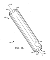
- FIGS: 1A and 1B show opposite sides of a sleeve anchor device with an attachment member comprising an opening.
- FIG. 2 shows a side view of a sleeve anchor device with an attachment member comprising an opening.
- FIG. 3 shows a side view of a sleeve anchor device with an attachment member comprising threads.
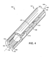
- FIG. 4 shows a side view of a sleeve anchor device with an attachment member comprising threads and the first sleeve end cut away.
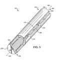
- FIG. 5 shows a threaded fastener positioned within a sleeve anchor device.
- FIGS. 1 - 5 illustrate various preferred embodiments of the push-in fasteners of the present invention.
- the present invention is not limited to these particular embodiments.
- FIGS. 1 - 5 Preferred embodiments of a sleeve anchor device of the present invention are provided in FIGS. 1 - 5.
- the sleeve anchor device is applicable for use as a ceiling hanger, and in particular, for use as a concrete ceiling hanger.
- the sleeve anchor device permits the supporting of heavy loads (e.g., electrical lines, plumbing lines, ceiling tiles, hanging conduits, and the like).
- the sleeve anchor device of the present invention has numerous advantages over previous prior art devices including, but not limited to, pull-out values exceeding industry standards, reduced insert forces, increased installation speeds, and reduced distortion upon heat treatment.
- the present invention is not limited to any particular mechanism. Indeed, an understanding of the mechanism is not necessary to practice the present invention.
- the sleeve anchor device functions on the principle that the device collapses in size as it is positioned in a hole, generating opposing forces between the device and the hole, thereby securing the device within the hole (described in more detail below).
- FIGS. 1A and 1B show opposite sides of a sleeve anchor embodiment of the present invention.
- a sleeve anchor 100 generally comprises an elongated sleeve 110. and an attachment member 120.
- the sleeve anchor 100 is not limited to a particular material composition (e.g., steel, iron, aluminum, or mixture thereof). In preferred embodiments, the material composition of the sleeve anchor 100 is metal.
- the sleeve anchor 100 is not limited to a particular length or width.
- the elongated sleeve 110 is configured to fit inside of a hole (e.g., pre-drilled hole) in a manner facilitating the securing of the sleeve anchor 100 within the hole. Additionally, in some embodiments, the elongated sleeve 110 is configured to accept and secure a threaded fastener. In preferred embodiments, the diameter of the elongated sleeve 110 is larger than the diameter of the hole, and insertion of the sleeve anchor 100 within the hole causes the elongated sleeve 110 to collapse in size.
- the elongated sleeve 110 comprises a first sleeve end 130, a second sleeve end 140, and has a longitudinal axis 150.
- the elongated sleeve 110 has therein a linear slot 160 defined by linear slot sleeve edges 170 and 180 (shown in FIG. 1B).
- the elongated sleeve 110 is hollow with openings 125 at the first sleeve end 130 and second sleeve end 140 .
- the elongated sleeve 110 is not limited to a particular shape (e.g., oval, square, tubular).
- the shape of the elongated sleeve 110 is tubular.
- the anchor sleeve 100 is configured to be secured within a hole (not shown) in a manner such that the second sleeve end 140 is inserted into a hole while the first sleeve end 130 is exposed outside of the hole.
- the longitudinal axis 150 runs along the length of the elongated sleeve 110 (e.g., from the first sleeve end 130 to the second sleeve end 140 ).
- the linear slot 160 extends along the length of the elongated sleeve 110 in parallel with the longitudinal axis 150.
- the linear slot 160 extends through the side of the elongated sleeve 110 thereby generating a gap opposed by the linear slot sleeve edges 170 and 180.
- the linear slot sleeve edges 170 and 180 are substantially linear.
- the linear slot 160 is not limited to a particular width.
- the collapsing of the elongated sleeve 110 as it is inserted into a hole causes a narrowing of the width of the linear slot 160 as the linear slot sleeve edges 170 and 180 are compressed towards one another.
- the linear slot 160 permits the sleeve anchor 100 to fit within various hole sizes through accommodation of its size. Additionally, the ability of the linear slot 160 to accommodate its width permits the sleeve anchor 100 to undergo various treatments (e.g., heat treatment) without comprising its overall shape due to treatment side effects (e.g., heat expansion).
- the attachment member 120 is not limited to a particular position along the sleeve anchor 100. In preferred embodiments, the attachment member 120 is positioned near the first sleeve end 130. Upon insertion of a sleeve anchor 100 into a hole, the attachment member 120 remains exposed outside of the hole, or at least accessible for further use. In some embodiments, the attachment member 120 serves to secure a fastener (e.g., threaded fastener) with the sleeve anchor 100.
- a fastener e.g., threaded fastener
- the attachment member 120 has therein an opening 190 through which a fastener or other device such as a wire hanger may be inserted.
- the opening 190 is not limited to a particular size.
- a feature of the present invention is that the anchor 100 can be easily inserted into a mating hole with a hammer or other suitable device.
- the linear slot 160 within the anchor 100 allows the elongated sleeve 110 to collapse a sufficient amount to provide a press/friction fit in the mating hole.
- FIG. 2 depicts an alternative anchor sleeve 100.
- the elongated sleeve 110 is hollow with openings 125 at the first sleeve end 130 and second sleeve end 140, and has therein a linear slot 160 opposed by linear slot edges 170 and 180.
- the linear slot 160 further is shown running in parallel with the longitudinal axis 150.
- the attachment member 120 is shown near the first sleeve end 130 having therein an opening 190 for accepting fasteners.
- FIG. 3 depicts an alternative anchor sleeve 100 embodiment, wherein the elongated sleeve 110 is hollow with openings 125 at the first sleeve end 130 and second sleeve end 140, and has therein a linear slot 160 opposed by linear slot edges 170 and 180.
- the linear slot 160 further is shown running in parallel with the longitudinal axis 150.
- the attachment member 120 includes threads 200 for accepting a threaded fastener.
- the threads 200 may be positioned on the interior or exterior of the elongated sleeve 110. In preferred embodiments, the threads 200 are positioned on the interior of the elongated sleeve 110.
- At least one of the linear slot sleeve edges 170 or 180 comprise at least one outwardly extending tab 210.
- two outwardly extending tabs 210 are positioned along one of the linear slot sleeve edges 170 or 180.
- the outwardly extending tabs 210 are not limited to a particular location along the length of a linear slot sleeve edge 170 or 180.
- the outwardly extending tabs 210 are not limited to a particular width or height.
- the outwardly extending tabs 210 prevent the linear slot sleeve edges 170 and 180 from engaging as the elongated sleeve 110 collapses.
- Preventing the linear slot sleeve edges 170 and 180 from engaging further protects the integrity of the sleeve anchor 100 upon insertion into a hole. Additionally, preventing the linear slot edges 170 and 180 from engaging protects the integrity of a threaded fastener secured within the elongated sleeve 110.
- the tabs 210 prevent the sleeve from collapsing to far during installation and upon heat treatment or other treatment of the anchor 100.
- FIG. 4 shows an anchor sleeve 100 embodiment with the first sleeve end 130 partially cut away.
- the elongated sleeve 110 is hollow with openings 125 at the first sleeve end 130 and second sleeve end 140, and has therein a linear slot 160 opposed by linear slot edges 170 and 180.
- One of the linear slot edges 180 is shown with two outwardly extending tabs 210.
- the linear slot 160 further is shown running in parallel with the longitudinal axis 150.
- the attachment member 120 is shown near the first sleeve end 130 having therein threads 200 for accepting fasteners.
- FIG. 5 depicts a threaded fastener 220 secured within a sleeve anchor 100 with the first sleeve end 130 cut away.
- the attachment member 120 is positioned near the first sleeve end 130 along the elongated sleeve 110.
- the attachment member 120 comprises threads 200 for accepting the threaded fastener 220.
- the linear slot 160 extends in parallel with the longitudinal axis 150 from the first sleeve end 130 to the second sleeve end 140.
- the linear slot is opposed by the linear slot sleeve edges 170 and 180.
- Two outwardly extending tabs 210 are positioned along one of the linear slot sleeve edges 170 or 180.
- the threaded fastener 220 is secured within the attachment member 120 and engaged with the threads 200.
- the threads 200 and elongated sleeve 110 are configured to be oversized in relation to the mating hole so that when the anchor 100 is placed within the mating hole, the elongated sleeve 110 will collapse just enough to secure the anchor 100 in the hole and allow the threads 200 to cooperate with the threads of the mating fastener.
Landscapes
- Engineering & Computer Science (AREA)
- General Engineering & Computer Science (AREA)
- Mechanical Engineering (AREA)
- Dowels (AREA)
- Joining Of Building Structures In Genera (AREA)
Abstract
Description
Claims (16)
- An anchor for insertion into a hole having sides, said anchor comprising:an elongated sleeve comprising two ends and an exterior surface, said elongated sleeve having a longitudinal axis and having therein a slot parallel to said longitudinal axis, said slot running the length of said elongated sleeve; andan attachment member on one of said two ends of said elongated sleeve, said elongated sleeve being insertable into the hole so that said linear slot collapses as said exterior surface of said elongated sleeve engages the sides of the hole thereby securing said elongated sleeve within the hole.
- The device of claim 1, wherein said linear slot is defined by opposing first and second sleeve edges.
- The device of claim 2, wherein said opposing first and second sleeve edges engage upon insertion of said device into the hole.
- The device of claim 2, wherein at least one of said opposing first and second sleeve edges comprises at least one outwardly extending tab.
- The device of claim 2, wherein the other of said opposing first and second sleeve edges is substantially linear.
- The device of claim 5, wherein said at least one outwardly extending tab engages said linear sleeve edge upon insertion of said device into the hole.
- The device of claim 1, wherein said attachment member comprises threads.
- The device of claim 7, wherein said threads are on the inside of said elongated sleeve and engageable with a threaded fastener.
- The device of claim 7, wherein said threads are on the outside of said elongated sleeve and engageable with a threaded fastener.
- The device of claim 1, wherein said attachment member comprises an outwardly extending member having an opening therein.
- An anchor device comprising:an elongated sleeve including two ends and an interior surface, said elongated sleeve having a longitudinal axis and having therein a slot parallel to said longitudinal axis, said slot running the length of said elongated sleeve and defined by opposing first and second sleeve edges, at least of one of said first and second sleeve edges having at least one outwardly extending tab; andan attachment member on one of said two ends of said elongated sleeve, said attachment member including threads on said interior surface of said end of said elongated sleeve, wherein upon compression of said elongated sleeve said slot collapses so that said outwardly extending tab engages the other of said sleeve edges, and wherein said threads are engageable with a threaded fastener.
- A system for anchoring an object in a hole comprising:an anchor device having an elongated sleeve comprising two ends and an interior surface, said elongated sleeve having a longitudinal axis and having therein a slot parallel to said longitudinal axis, said slot running the length of said elongated sleeve and defined by opposing first and second sleeve edges, said anchor device further having an attachment member on one of said two ends of said elongated sleeve, said attachment member comprising threads on said surface of said end of said elongated sleeve, said anchor being adapted for insertion into the hole; anda threaded fastener for engagement with said threads of said attachment member.
- The system of claim 12, wherein said opposing first and second sleeve edges are configured to engage one another upon compression of said elongated sleeve by inserting said elongated sleeve into said hole so that said threads are engageable with said threaded fastener.
- The system of claim 13, wherein at least one of said opposing first and second sleeve edges comprises at least one outwardly extending tab, wherein upon compression of said elongated sleeve said slot collapses so that said outwardly extending tab engages the other of said sleeve edges and said threads are engageable with said threaded fastener.
- The system of claim 13, wherein said threads are on the interior surface of said surface of said end of said elongated sleeve.
- The system of claim 13, wherein said threads are on the exterior surface of said surface of said end of said elongated sleeve.
Applications Claiming Priority (4)
| Application Number | Priority Date | Filing Date | Title |
|---|---|---|---|
| US555391 | 1995-11-09 | ||
| US52704 | 1998-03-31 | ||
| US55539104P | 2004-03-22 | 2004-03-22 | |
| US11/052,704 US20050207861A1 (en) | 2004-03-22 | 2005-02-07 | Anchoring device |
Publications (2)
| Publication Number | Publication Date |
|---|---|
| EP1580443A2 true EP1580443A2 (en) | 2005-09-28 |
| EP1580443A3 EP1580443A3 (en) | 2006-11-22 |
Family
ID=34986457
Family Applications (1)
| Application Number | Title | Priority Date | Filing Date |
|---|---|---|---|
| EP05005433A Withdrawn EP1580443A3 (en) | 2004-03-22 | 2005-03-12 | Anchoring Device |
Country Status (2)
| Country | Link |
|---|---|
| US (1) | US20050207861A1 (en) |
| EP (1) | EP1580443A3 (en) |
Families Citing this family (5)
| Publication number | Priority date | Publication date | Assignee | Title |
|---|---|---|---|---|
| USD590243S1 (en) * | 2007-06-11 | 2009-04-14 | Bush Denis C | Lug nut |
| USD583656S1 (en) * | 2007-08-29 | 2008-12-30 | Bush Denis C | Lug nut |
| USD713714S1 (en) * | 2013-12-24 | 2014-09-23 | Kyo-Ei Industrial Corporation | Cap for wheel nut |
| USD710683S1 (en) * | 2013-12-24 | 2014-08-12 | Kyo-Ei Industrial Corporation | Wheel nut |
| USD871900S1 (en) * | 2017-06-16 | 2020-01-07 | Cobra Fixations Cie Ltee—Cobra Anchors Co. Ltd. | Wall anchor |
Family Cites Families (21)
| Publication number | Priority date | Publication date | Assignee | Title |
|---|---|---|---|---|
| US1116710A (en) * | 1913-06-21 | 1914-11-10 | Clements Company | Bolt-anchor. |
| US1166525A (en) * | 1914-12-04 | 1916-01-04 | Carl Joseph | Bolt-anchor blank. |
| US2575481A (en) * | 1946-03-30 | 1951-11-20 | Stanley W Anderson | Wire fastener |
| US3027670A (en) * | 1960-02-05 | 1962-04-03 | Gen Classics Inc | Trophy figure mounting means |
| US3132557A (en) * | 1960-08-03 | 1964-05-12 | Northern Ordnance Inc | Friction type dowel and ring keeper therefor |
| US3217586A (en) * | 1963-04-19 | 1965-11-16 | Bishop & Babcock Corp | Threaded sleeve including an edge abutment retaining means |
| BE656476A (en) * | 1964-11-30 | 1965-03-16 | ||
| US3442170A (en) * | 1967-10-05 | 1969-05-06 | Roder Prazision Wilhelm Roder | Sleeve adaptor |
| US3710674A (en) * | 1970-12-18 | 1973-01-16 | Meteor Res Ltd | Expandable fastener |
| DE2412901C2 (en) * | 1974-03-18 | 1983-06-30 | Hilti AG, 9494 Schaan | Expansion anchor |
| US4022101A (en) * | 1974-10-31 | 1977-05-10 | Arbman Development Ab | Screw-socket fixture |
| DE2657353A1 (en) * | 1976-12-17 | 1978-06-29 | Hilti Ag | EXPANSION DOWEL |
| US4135432A (en) * | 1977-11-21 | 1979-01-23 | Drillco Equipment Company, Inc. | Anchor for undercut bore |
| DE3816661A1 (en) * | 1988-05-17 | 1989-11-23 | Rockenfeller Kg | PIPE DOWEL FOR DRIVING IN GAS OR LIGHTWEIGHT CONCRETE OR THE LIKE |
| US4978265A (en) * | 1989-06-28 | 1990-12-18 | Wan Thomas E De | Sleeve anchor for screw |
| US5036674A (en) * | 1989-11-07 | 1991-08-06 | Carrier Corporation | Accumulator mounting method and apparatus |
| DE9103621U1 (en) * | 1991-03-23 | 1991-07-25 | Feintool International Holding, Lyss | Element for positioning components |
| ES2104159T3 (en) * | 1992-07-30 | 1997-10-01 | Splitfast Technologies Limited | WELDING PINS, WELDING APPARATUS FOR WELDING A FIXING ELEMENT AND PROCEDURE FOR FIXING A MOUNTING PART ON A WELDED FIXING ELEMENT. |
| FR2697301B1 (en) * | 1992-10-23 | 1995-01-13 | Socapex Amphenol | Rivet device with zero insertion force. |
| DE19620955A1 (en) * | 1996-05-24 | 1997-11-27 | Hilti Ag | Fastening system and method for creating fasteners |
| DE10034799A1 (en) * | 2000-07-18 | 2002-01-31 | Fischer Artur Werke Gmbh | Air layer anchor for concrete building has anchor rod secured to tensioning sleeve via right-angle end fitting into opening in sleeve wall |
-
2005
- 2005-02-07 US US11/052,704 patent/US20050207861A1/en not_active Abandoned
- 2005-03-12 EP EP05005433A patent/EP1580443A3/en not_active Withdrawn
Also Published As
| Publication number | Publication date |
|---|---|
| EP1580443A3 (en) | 2006-11-22 |
| US20050207861A1 (en) | 2005-09-22 |
Similar Documents
| Publication | Publication Date | Title |
|---|---|---|
| FI73505C (en) | Fasteners. | |
| US3709089A (en) | Captive fastening element | |
| US4130977A (en) | Concrete insert | |
| EP0834658A3 (en) | Bolt anchoring device | |
| JPH0446211A (en) | Anchor bolt having spring | |
| US7780132B1 (en) | Construction hanger | |
| KR20140137879A (en) | Anchor assembly for exterior materials including insulation of concrete wall | |
| EP1580443A2 (en) | Anchoring Device | |
| FI76189B (en) | ANORDNING FOER FOERANKRING I BETONG. | |
| US3396930A (en) | Support penetrating bracket | |
| US20190323630A1 (en) | Holding device for cables or pipes | |
| US20100011693A1 (en) | Shear plate | |
| JP3207104U (en) | Piping support with drop prevention function | |
| US4246688A (en) | Method of anchoring in concrete | |
| KR101973400B1 (en) | Apparatus for Assembling Wire-rope, and Method for Assembling Wire-rope Using The Same | |
| KR940007069Y1 (en) | Gas Piping Pipe Fixture | |
| US20060182511A1 (en) | Mounting device | |
| JP3538778B2 (en) | Fall-off prevention device for mounting bracket | |
| JP7369832B1 (en) | Piping fixing fittings | |
| JP2005036940A (en) | Fastening fixture anti-come-off structure and piping band | |
| JP3078239U (en) | Expansion anchor | |
| EP0733812B1 (en) | Blind fastener device | |
| KR200414300Y1 (en) | Anchor nut | |
| AU2007214295B2 (en) | Shear plate | |
| JPH0369419B2 (en) |
Legal Events
| Date | Code | Title | Description |
|---|---|---|---|
| PUAI | Public reference made under article 153(3) epc to a published international application that has entered the european phase |
Free format text: ORIGINAL CODE: 0009012 |
|
| 17P | Request for examination filed |
Effective date: 20050312 |
|
| AK | Designated contracting states |
Kind code of ref document: A2 Designated state(s): AT BE BG CH CY CZ DE DK EE ES FI FR GB GR HU IE IS IT LI LT LU MC NL PL PT RO SE SI SK TR |
|
| AX | Request for extension of the european patent |
Extension state: AL BA HR LV MK YU |
|
| PUAL | Search report despatched |
Free format text: ORIGINAL CODE: 0009013 |
|
| AK | Designated contracting states |
Kind code of ref document: A3 Designated state(s): AT BE BG CH CY CZ DE DK EE ES FI FR GB GR HU IE IS IT LI LT LU MC NL PL PT RO SE SI SK TR |
|
| AX | Request for extension of the european patent |
Extension state: AL BA HR LV MK YU |
|
| RIC1 | Information provided on ipc code assigned before grant |
Ipc: F16B 13/06 20060101AFI20050706BHEP |
|
| AKX | Designation fees paid |
Designated state(s): DE ES FR GB IT |
|
| 17Q | First examination report despatched |
Effective date: 20100824 |
|
| STAA | Information on the status of an ep patent application or granted ep patent |
Free format text: STATUS: THE APPLICATION IS DEEMED TO BE WITHDRAWN |
|
| 18D | Application deemed to be withdrawn |
Effective date: 20110104 |